

SENT/SPC Driver for the MPC560xP and MPC564xL Microcontroller ...
SENT/SPC Driver for the MPC560xP and MPC564xL Microcontroller ...
SENT/SPC Driver for the MPC560xP and MPC564xL Microcontroller ...

Create successful ePaper yourself
Turn your PDF publications into a flip-book with our unique Google optimized e-Paper software.
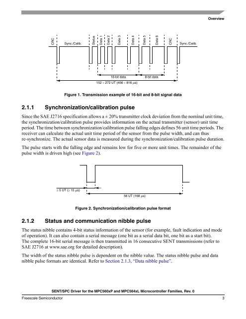
CRC<br />
Sync./Calib. Status<br />
Figure 1. Transmission example of 16-bit <strong>and</strong> 8-bit signal data<br />
2.1.1 Synchronization/calibration pulse<br />
<strong>SENT</strong>/<strong>SPC</strong> <strong>Driver</strong> <strong>for</strong> <strong>the</strong> <strong>MPC560xP</strong> <strong>and</strong> <strong>MPC564xL</strong> <strong>Microcontroller</strong> Families, Rev. 0<br />
Overview<br />
Since <strong>the</strong> SAE J2716 specification allows a ± 20% transmitter clock deviation from <strong>the</strong> nominal unit time,<br />
<strong>the</strong> synchronization/calibration pulse provides in<strong>for</strong>mation on <strong>the</strong> actual transmitter (sensor) unit time<br />
period. The time between synchronization/calibration pulse falling edges defines 56 unit time periods. The<br />
receiver can calculate <strong>the</strong> actual unit time period of <strong>the</strong> sensor from <strong>the</strong> pulse width, <strong>and</strong> can thus<br />
re-synchronize. The actual sensor data is measured during <strong>the</strong> synchronization/calibration pulse duration.<br />
The pulse starts with <strong>the</strong> falling edge <strong>and</strong> remains low <strong>for</strong> five or more unit times. The remainder of <strong>the</strong><br />
pulse width is driven high (see Figure 2).<br />
≥ 5 UT (≥ 15 μs)<br />
Figure 2. Synchronization/calibration pulse <strong>for</strong>mat<br />
2.1.2 Status <strong>and</strong> communication nibble pulse<br />
Data 1<br />
Data 2<br />
Data 3<br />
The status nibble contains 4-bit status in<strong>for</strong>mation of <strong>the</strong> sensor (<strong>for</strong> example, fault indication <strong>and</strong> mode<br />
of operation). It can also contain a serial message (one bit as a serial data bit, one bit as a start bit).<br />
The complete 16-bit serial message is <strong>the</strong>n transmitted in 16 consecutive <strong>SENT</strong> transmissions (refer to<br />
SAE J2716 at www.sae.org <strong>for</strong> detailed description).<br />
The width of <strong>the</strong> status nibble pulse is dependent on <strong>the</strong> nibble value. The status nibble pulse <strong>and</strong> data<br />
nibble pulse <strong>for</strong>mats are identical. Refer to Section 2.1.3, “Data nibble pulse”.<br />
Freescale Semiconductor 3<br />
Data 4<br />
152 ÷ 272 UT (456 ÷ 816 μs)<br />
Data 5<br />
Data 6<br />
16-bit data 8-bit data<br />
56 UT (168 μs)<br />
CRC<br />
Sync./Calib.


