

SENT/SPC Driver for the MPC560xP and MPC564xL Microcontroller ...
SENT/SPC Driver for the MPC560xP and MPC564xL Microcontroller ...
SENT/SPC Driver for the MPC560xP and MPC564xL Microcontroller ...

You also want an ePaper? Increase the reach of your titles
YUMPU automatically turns print PDFs into web optimized ePapers that Google loves.
NOTE<br />
The driver CRC calculation also includes <strong>the</strong> status <strong>and</strong> communication<br />
nibble value as it is primarily intended <strong>for</strong> use with <strong>the</strong> Infineon TLE4889C<br />
Hall sensor.<br />
2.2 <strong>SPC</strong> protocol<br />
<strong>SENT</strong>/<strong>SPC</strong> <strong>Driver</strong> <strong>for</strong> <strong>the</strong> <strong>MPC560xP</strong> <strong>and</strong> <strong>MPC564xL</strong> <strong>Microcontroller</strong> Families, Rev. 0<br />
Overview<br />
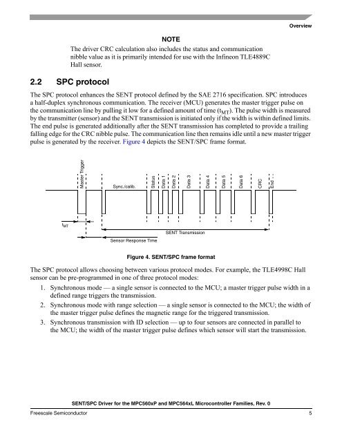
The <strong>SPC</strong> protocol enhances <strong>the</strong> <strong>SENT</strong> protocol defined by <strong>the</strong> SAE 2716 specification. <strong>SPC</strong> introduces<br />
a half-duplex synchronous communication. The receiver (MCU) generates <strong>the</strong> master trigger pulse on<br />
<strong>the</strong> communication line by pulling it low <strong>for</strong> a defined amount of time (t MT ). The pulse width is measured<br />
by <strong>the</strong> transmitter (sensor) <strong>and</strong> <strong>the</strong> <strong>SENT</strong> transmission is initiated only if <strong>the</strong> width is within defined limits.<br />
The end pulse is generated additionally after <strong>the</strong> <strong>SENT</strong> transmission has completed to provide a trailing<br />
falling edge <strong>for</strong> <strong>the</strong> CRC nibble pulse. The communication line <strong>the</strong>n remains idle until a new master trigger<br />
pulse is generated by <strong>the</strong> receiver. Figure 4 depicts <strong>the</strong> <strong>SENT</strong>/<strong>SPC</strong> frame <strong>for</strong>mat.<br />
t MT<br />
Master Trigger<br />
Sync./calib. Status<br />
Sensor Response Time<br />
Data 1<br />
Data 2<br />
<strong>SENT</strong> Transmission<br />
Figure 4. <strong>SENT</strong>/<strong>SPC</strong> frame <strong>for</strong>mat<br />
The <strong>SPC</strong> protocol allows choosing between various protocol modes. For example, <strong>the</strong> TLE4998C Hall<br />
sensor can be pre-programmed in one of three protocol modes:<br />
1. Synchronous mode — a single sensor is connected to <strong>the</strong> MCU; a master trigger pulse width in a<br />
defined range triggers <strong>the</strong> transmission.<br />
2. Synchronous mode with range selection — a single sensor is connected to <strong>the</strong> MCU; <strong>the</strong> width of<br />
<strong>the</strong> master trigger pulse defines <strong>the</strong> magnetic range <strong>for</strong> <strong>the</strong> triggered transmission.<br />
3. Synchronous transmission with ID selection — up to four sensors are connected in parallel to<br />
<strong>the</strong> MCU; <strong>the</strong> width of <strong>the</strong> master trigger pulse defines which sensor will start <strong>the</strong> transmission.<br />
Freescale Semiconductor 5<br />
Data 3<br />
Data 4<br />
Data 5<br />
Data 6<br />
CRC<br />
End


