Induction and Alternating Current with teacher's notes
Induction and Alternating Current with teacher's notes
Induction and Alternating Current with teacher's notes

You also want an ePaper? Increase the reach of your titles
YUMPU automatically turns print PDFs into web optimized ePapers that Google loves.
22-2<br />
<strong>Alternating</strong> current, generators,<br />
<strong>and</strong> motors<br />
GENERATORS AND ALTERNATING CURRENT<br />
In the previous section you learned that a current can be induced in a circuit<br />
either by changing the magnetic field strength or by moving the circuit loop<br />
in or out of the magnetic field. Another way to induce a current is to change<br />
the orientation of the loop <strong>with</strong> respect to the magnetic field.<br />
This second approach to inducing a current represents a practical means of generating<br />
electrical energy. In effect, the mechanical energy used to turn the loop is<br />
converted to electrical energy. A device that does this is called an electric generator.<br />
In most commercial power plants, mechanical energy is provided in the form<br />
of rotational motion. For example, in a hydroelectric plant, falling water directed<br />
against the blades of a turbine causes the turbine to turn; in a coal or natural-gasburning<br />
plant, energy produced by burning fuel is used to convert water to<br />
steam, <strong>and</strong> this steam is directed against the turbine blades to turn the turbine.<br />
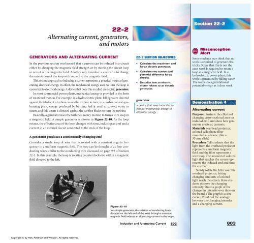
Basically, a generator uses the turbine’s rotary motion to turn a wire loop in<br />
a magnetic field. A simple generator is shown in Figure 22-10. As the loop<br />
rotates, the effective area of the loop changes <strong>with</strong> time, inducing an emf <strong>and</strong> a<br />
current in an external circuit connected to the ends of the loop.<br />
A generator produces a continuously changing emf<br />
Consider a single loop of wire that is rotated <strong>with</strong> a constant angular frequency<br />
in a uniform magnetic field. The loop can be thought of as four conducting<br />
wires similar to the conducting wire discussed on page 795 of Section<br />
22-1. In this example, the loop is rotating counterclockwise <strong>with</strong>in a magnetic<br />
field directed to the left.<br />
Copyright © by Holt, Rinehart <strong>and</strong> Winston. All rights reserved.<br />
22-2 SECTION OBJECTIVES<br />
• Calculate the maximum emf<br />
for an electric generator.<br />
• Calculate rms current <strong>and</strong><br />
potential difference for ac<br />
circuits.<br />
• Describe how an electric<br />
motor relates to an electric<br />
generator.<br />
generator<br />
a device that uses induction to<br />
convert mechanical energy to<br />
electrical energy<br />
Figure 22-10<br />
In a simple generator, the rotation of conducting loops<br />
(located on the left end of the axis) through a constant<br />
magnetic field induces an alternating current in the loops.<br />
<strong>Induction</strong> <strong>and</strong> <strong>Alternating</strong> <strong>Current</strong><br />
803<br />
Section 22-2<br />
STOP<br />
Misconception<br />
Alert<br />
Some students may think that no<br />
work is required to generate electricity.<br />
Stress that this is not the<br />
case; work is required to rotate a<br />
loop in a magnetic field. In a<br />
hydroelectric power plant, this<br />
work is generated by falling water.<br />
The water loses gravitational<br />
potential energy as it does work.<br />
Demonstration 4<br />
<strong>Alternating</strong> current<br />
Purpose Illustrate the effects of<br />
changing cross-sectional area on<br />
induced emf, <strong>and</strong> show how generators<br />
create ac currents.<br />
Materials overhead projector,<br />
colored cellophane filter<br />
mounted in a frame (like a<br />
35 mm slide)<br />
Procedure Tell students that the<br />
light from the overhead projector<br />
represents a uniform magnetic<br />
field <strong>and</strong> the filter represents a<br />
wire loop. The amount of colored<br />
light that reaches the screen represents<br />
the induced emf <strong>and</strong> thus<br />
the current.<br />
Slowly rotate the filter over the<br />
overhead projector, letting<br />
changing amounts of colored<br />
light reach the screen. Have students<br />
observe the changing<br />
intensity. Draw a graph of the<br />
changes in intensity over time on<br />
the board. (The graph is a sine<br />
curve.) Point out the analogy<br />
between the changing intensity<br />
<strong>and</strong> a changing current.<br />
803