Induction and Alternating Current with teacher's notes
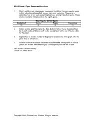
Induction and Alternating Current with teacher's notes
Induction and Alternating Current with teacher's notes

Create successful ePaper yourself
Turn your PDF publications into a flip-book with our unique Google optimized e-Paper software.
Section 22-3<br />
Demonstration 8<br />
Transformers<br />
Purpose Show students how a<br />
transformer works, <strong>and</strong> reinforce<br />
the idea that a changing current<br />
is required.<br />
Materials iron bar, 9 V battery,<br />
knife switch, flashlight bulb in<br />
holder, two wires (each about<br />
1 m long)<br />
Procedure Set up the primary side<br />
of the transformer before class by<br />
connecting the battery <strong>and</strong> switch<br />
in series <strong>with</strong> one of the wires<br />
coiled around the iron bar. The<br />
primary coil should have 50 turns.<br />
Set up the secondary coil <strong>with</strong> 25<br />
turns, <strong>and</strong> connect the flashlight<br />
bulb to the secondary coil.<br />
In class, demonstrate this stepdown<br />
transformer by momentarily<br />
closing the switch <strong>and</strong> then<br />
opening it again. Have students<br />
discuss the transfer of energy that<br />
occurs in this situation.<br />
Close the switch <strong>and</strong> keep it<br />
closed. Have students note the<br />
behavior of the bulb. Discuss the<br />
brief illumination <strong>and</strong> fading of<br />
the bulb <strong>with</strong> students. Lead students<br />
to consider the concept of<br />
changing current. Open the<br />
switch, <strong>and</strong> note the illumination.<br />
Discuss this effect.<br />
814<br />
22-3 SECTION OBJECTIVES<br />
• Describe how mutual<br />
induction occurs in circuits.<br />
• Calculate the potential<br />
difference from a step-up or<br />
step-down transformer.<br />
• Describe how self-induction<br />
occurs in an electric circuit.<br />
mutual inductance<br />
a measure of the ability of one circuit<br />
carrying a changing current to<br />
induce an emf in a nearby circuit<br />
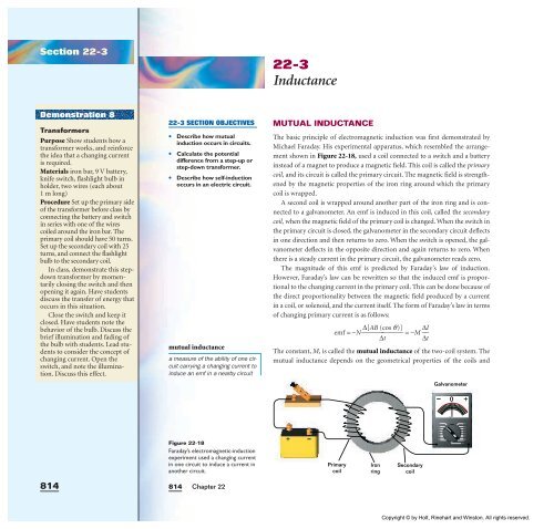
Figure 22-18<br />
Faraday’s electromagnetic-induction<br />
experiment used a changing current<br />
in one circuit to induce a current in<br />
another circuit.<br />
814<br />
Chapter 22<br />
22-3<br />
Inductance<br />
MUTUAL INDUCTANCE<br />
The basic principle of electromagnetic induction was first demonstrated by<br />
Michael Faraday. His experimental apparatus, which resembled the arrangement<br />
shown in Figure 22-18, used a coil connected to a switch <strong>and</strong> a battery<br />
instead of a magnet to produce a magnetic field. This coil is called the primary<br />
coil, <strong>and</strong> its circuit is called the primary circuit. The magnetic field is strengthened<br />
by the magnetic properties of the iron ring around which the primary<br />
coil is wrapped.<br />
A second coil is wrapped around another part of the iron ring <strong>and</strong> is connected<br />
to a galvanometer. An emf is induced in this coil, called the secondary<br />
coil, when the magnetic field of the primary coil is changed. When the switch in<br />
the primary circuit is closed, the galvanometer in the secondary circuit deflects<br />
in one direction <strong>and</strong> then returns to zero. When the switch is opened, the galvanometer<br />
deflects in the opposite direction <strong>and</strong> again returns to zero. When<br />
there is a steady current in the primary circuit, the galvanometer reads zero.<br />
The magnitude of this emf is predicted by Faraday’s law of induction.<br />
However, Faraday’s law can be rewritten so that the induced emf is proportional<br />
to the changing current in the primary coil. This can be done because of<br />
the direct proportionality between the magnetic field produced by a current<br />
in a coil, or solenoid, <strong>and</strong> the current itself. The form of Faraday’s law in terms<br />
of changing primary current is as follows:<br />
emf =−N⎯ ∆[AB (cos<br />
q)]<br />
⎯ =−M ⎯<br />
∆t<br />
∆I<br />
⎯<br />
∆t<br />
The constant, M, is called the mutual inductance of the two-coil system. The<br />
mutual inductance depends on the geometrical properties of the coils <strong>and</strong><br />
+<br />
Primary<br />
coil<br />
Iron<br />
ring<br />
Secondary<br />
coil<br />
Galvanometer<br />
100<br />
200<br />
300<br />
400<br />
500<br />
600<br />
700<br />
800<br />
900<br />
0 +<br />
100<br />
200<br />
300<br />
400<br />
500<br />
600<br />
700<br />
800<br />
900<br />
1000<br />
Copyright © by Holt, Rinehart <strong>and</strong> Winston. All rights reserved.