Induction and Alternating Current with teacher's notes
Induction and Alternating Current with teacher's notes
Induction and Alternating Current with teacher's notes

Create successful ePaper yourself
Turn your PDF publications into a flip-book with our unique Google optimized e-Paper software.
SECTION 22-3<br />
Teaching Tip<br />
Some students may wonder<br />
whether dc transformers are possible.<br />
The dc produced by a battery<br />
would not work <strong>with</strong> a<br />
transformer. This is because a<br />
changing current is required, <strong>and</strong><br />
a battery generates a steady direct<br />
current. However, as seen on page<br />
811, a generator can produce a<br />
fluctuating direct current. Such a<br />
current could be used by a<br />
transformer.<br />
Teaching Tip<br />
Point out to students that spark<br />
plugs create a spark because the<br />
potential difference across the gap<br />
increases to 20 000 V. At such<br />
high potential differences, air is<br />
ionized <strong>and</strong> becomes a conductor.<br />
816<br />
816<br />
Step-up transfomer<br />
(ignition coil)<br />
Ignition<br />
switch<br />
+<br />
Chapter 22<br />
–<br />
12 V battery<br />
Another way to express this equation is to equate the ratio of the potential differences<br />
to the ratio of the number of turns.<br />
∆V2<br />
⎯⎯<br />
= ⎯<br />
∆V1<br />
N2<br />
⎯<br />
N1<br />
When N2 is greater than N1, the secondary potential difference is greater<br />
than that of the primary, <strong>and</strong> the transformer is called a step-up transformer.<br />
When N2 is less than N1, the secondary potential difference is less than that<br />
of the primary, <strong>and</strong> the transformer is called a step-down transformer.<br />
It may seem that a transformer provides something for nothing. For<br />
example, a step-up transformer can change an input potential difference<br />
from 10 V to 100 V. However, the power input at the primary must equal the<br />
power output at the secondary. An increase in potential difference at the secondary<br />
means that there must be a proportional decrease in current. If the<br />
potential difference at the secondary is 10 times that at the primary, then the<br />
current at the secondary is reduced by a factor of 10.<br />
Computer<br />
Crank angle<br />
sensor<br />
Spark plug<br />
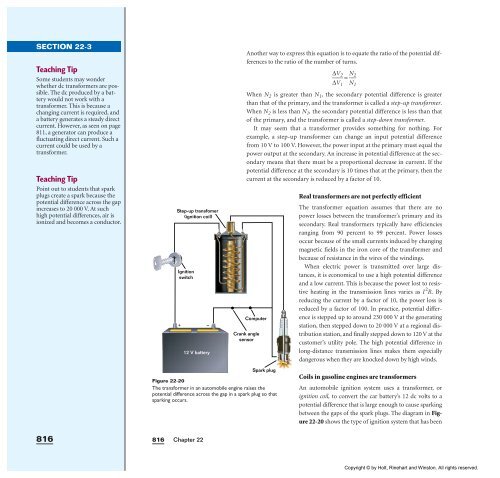
Figure 22-20<br />
The transformer in an automobile engine raises the<br />
potential difference across the gap in a spark plug so that<br />
sparking occurs.<br />
Real transformers are not perfectly efficient<br />
The transformer equation assumes that there are no<br />
power losses between the transformer’s primary <strong>and</strong> its<br />
secondary. Real transformers typically have efficiencies<br />
ranging from 90 percent to 99 percent. Power losses<br />
occur because of the small currents induced by changing<br />
magnetic fields in the iron core of the transformer <strong>and</strong><br />
because of resistance in the wires of the windings.<br />
When electric power is transmitted over large distances,<br />
it is economical to use a high potential difference<br />
<strong>and</strong> a low current. This is because the power lost to resistive<br />
heating in the transmission lines varies as I 2 R. By<br />
reducing the current by a factor of 10, the power loss is<br />
reduced by a factor of 100. In practice, potential difference<br />
is stepped up to around 230 000 V at the generating<br />
station, then stepped down to 20 000 V at a regional distribution<br />
station, <strong>and</strong> finally stepped down to 120 V at the<br />
customer’s utility pole. The high potential difference in<br />
long-distance transmission lines makes them especially<br />
dangerous when they are knocked down by high winds.<br />
Coils in gasoline engines are transformers<br />
An automobile ignition system uses a transformer, or<br />
ignition coil, to convert the car battery’s 12 dc volts to a<br />
potential difference that is large enough to cause sparking<br />
between the gaps of the spark plugs. The diagram in Figure<br />
22-20 shows the type of ignition system that has been<br />
Copyright © by Holt, Rinehart <strong>and</strong> Winston. All rights reserved.