Induction and Alternating Current with teacher's notes
Induction and Alternating Current with teacher's notes
Induction and Alternating Current with teacher's notes

Create successful ePaper yourself
Turn your PDF publications into a flip-book with our unique Google optimized e-Paper software.
As the current increases, the rate of increase lessens <strong>and</strong> the induced emf<br />
decreases, as shown in Figure 22-22. The decrease in the induced emf results<br />
in a gradual increase in the current. Similarly, when the switch is opened,<br />
the current gradually decreases to zero. This effect is called self-induction<br />
because the changing magnetic field through the circuit arises from the current<br />
in the circuit itself. The induced emf in this case is called self-induced emf.<br />
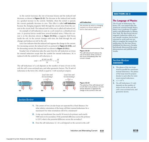
An example of self-induction is seen in a coil wound on a cylindrical iron<br />
core. (A practical device would have several hundred turns.) When the current<br />
is in the direction shown in Figure 22-23(a), a magnetic field forms<br />
inside the coil. As the current changes <strong>with</strong> time, the field through the coil<br />
changes <strong>and</strong> induces an emf in the coil.<br />
Lenz’s law indicates that this induced emf opposes the change in the current.<br />
For increasing current, the induced emf is as pictured in Figure 22-23(b), <strong>and</strong><br />
for decreasing current, the induced emf is as shown in Figure 22-23(c).<br />
Faraday’s law of induction takes the same form for self-induction as it does<br />
for mutual induction except that the symbol for mutual inductance, M, is<br />
replaced <strong>with</strong> the symbol for self-inductance, L.<br />
emf =−N⎯ ∆[AB (cos<br />
q)]<br />
⎯ =−L ⎯<br />
∆t<br />
∆I<br />
⎯<br />
∆t<br />
The self-inductance of a coil depends on the number of turns of wire in the<br />
coil, the coil’s cross-sectional area, <strong>and</strong> other geometric factors. The SI unit of<br />
inductance is the henry (H), which is equal to 1 volt-second per ampere.<br />
B<br />
I<br />
Lenz’s law emf<br />
for increasing I<br />
− +<br />
(a) (b) (c)<br />
Section Review<br />
Copyright © by Holt, Rinehart <strong>and</strong> Winston. All rights reserved.<br />
Lenz’s law emf<br />
for decreasing I<br />
+ −<br />
self-induction<br />
1. The centers of two circular loops are separated by a fixed distance. For<br />
what relative orientation of the loops will their mutual inductance be a<br />
maximum? For what orientation will it be a minimum?<br />
2. A step-up transformer has exactly 50 turns in its primary <strong>and</strong> exactly<br />
7000 turns in its secondary. If the potential difference across the primary<br />
is 120 V, what is the potential difference across the secondary?<br />
3. Does the self-inductance (L) of a coil depend on the current in the coil?<br />
the process by which a changing<br />
current in a circuit induces an<br />
emf in that same circuit<br />
<strong>Current</strong><br />
Figure 22-22<br />
The self-induced emf reduces the<br />
rate of increase of the current in<br />
the circuit immediately after the<br />
circuit is closed.<br />
<strong>Induction</strong> <strong>and</strong> <strong>Alternating</strong> <strong>Current</strong><br />
Time<br />
Figure 22-23<br />
The polarity of the self-induced emf<br />
is such that it can produce a current<br />
whose direction is opposite the<br />
change in the current in the coil.<br />
819<br />
SECTION 22-3<br />
The Language of Physics<br />
The SI unit of inductance, the<br />
henry (H), was named after the<br />
American scientist Joseph Henry.<br />
Henry was a professor of mathematics<br />
<strong>and</strong> philosophy in Albany,<br />
New York. He discovered electromagnetic<br />
induction while on a<br />
one-month vacation, but he then<br />
returned to work <strong>and</strong> was not<br />
able to complete his research for<br />
publication. By the time Henry<br />
published his discovery, Faraday<br />
had already discovered the same<br />
phenomenon <strong>and</strong> published his<br />
results.<br />
Section Review<br />
ANSWERS<br />
1. The planes of the two loops<br />
must be parallel for maximum<br />
mutual inductance. The planes<br />
of the loops must be perpendicular<br />
to each other for minimum<br />
mutual inductance.<br />
2. 1.7 × 10 4 V<br />
3. No, self-inductance (L) only<br />
depends on the number of<br />
turns of wire in the coil, the<br />
coil’s cross-sectional area, <strong>and</strong><br />
geometric factors.<br />
819