

Thermocouple color codes - Educypedia
Thermocouple color codes - Educypedia
Thermocouple color codes - Educypedia

Create successful ePaper yourself
Turn your PDF publications into a flip-book with our unique Google optimized e-Paper software.
H3 Color Codes-MM3.qxd 1/23/04 11:44 AM Page 3<br />
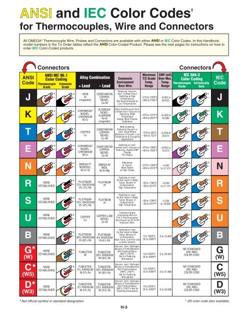
ANSI and IEC Color Codes †<br />
for <strong>Thermocouple</strong>s, Wire and Connectors<br />
All OMEGA ® <strong>Thermocouple</strong> Wire, Probes and Connectors are available with either ANSI or IEC Color Codes. In this Handbook,<br />
model numbers in the To Order tables reflect the ANSI Color-Coded Product. Please see the next pages for instructions on how to<br />
order IEC Color-Coded products.<br />
ANSI<br />
Code<br />
J<br />
K<br />
T<br />
E<br />
N<br />
R<br />
S<br />
U<br />
B<br />
G*<br />
(W)<br />
C*<br />
(W5)<br />
D*<br />
(W3)<br />
Connectors Connectors<br />
ANSI MC 96.1<br />
Color Coding<br />
<strong>Thermocouple</strong> Extension<br />
Grade Grade<br />
+<br />
–<br />
+<br />
–<br />
+<br />
–<br />
+<br />
–<br />
+<br />
–<br />
NONE<br />
ESTABLISHED<br />
NONE<br />
ESTABLISHED<br />
NONE<br />
ESTABLISHED<br />
NONE<br />
ESTABLISHED<br />
NONE<br />
ESTABLISHED<br />
NONE<br />
ESTABLISHED<br />
NONE<br />
ESTABLISHED<br />
+<br />
–<br />
+<br />
–<br />
+<br />
–<br />
+<br />
–<br />
+<br />
–<br />
+<br />
–<br />
+<br />
–<br />
+<br />
–<br />
+<br />
–<br />
+<br />
–<br />
+<br />
–<br />
+<br />
–<br />
* Not official symbol or standard designation<br />
Alloy Combination<br />
+ Lead – Lead<br />
IRON<br />
Fe<br />
(magnetic)<br />
CHROMEGA ®<br />
NICKEL-<br />
CHROMIUM<br />
Ni-Cr<br />
COPPER<br />
Cu<br />
CHROMEGA ®<br />
NICKEL-<br />
CHROMIUM<br />
Ni-Cr<br />
OMEGA-P ®<br />
NICROSIL<br />
Ni-Cr-Si<br />
PLATINUM-<br />
13% RHODIUM<br />
Pt-13% Rh<br />
PLATINUM-<br />
10% RHODIUM<br />
Pt-10% Rh<br />
COPPER<br />
Cu<br />
PLATINUM-<br />
30% RHODIUM<br />
Pt-30% Rh<br />
TUNGSTEN<br />
W<br />
TUNGSTEN-<br />
5% RHENIUM<br />
W-5% Re<br />
TUNGSTEN-<br />
3% RHENIUM<br />
W-3% Re<br />
CONSTANTAN<br />
COPPER-<br />
NICKEL<br />
Cu-Ni<br />
ALOMEGA ®<br />
NICKEL-<br />
ALUMINUM<br />
Ni-AI<br />
(magnetic)<br />
CONSTANTAN<br />
COPPER-<br />
NICKEL<br />
Cu–Ni<br />
CONSTANTAN<br />
COPPER-<br />
NICKEL<br />
Cu-Ni<br />
OMEGA-N ®<br />
NISIL<br />
Ni-Si-Mg<br />
PLATINUM<br />
Pt<br />
PLATINUM<br />
Pt<br />
COPPER-LOW<br />
NICKEL<br />
Cu-Ni<br />
PLATINUM-<br />
6% RHODIUM<br />
Pt-6% Rh<br />
TUNGSTEN-<br />
26% RHENIUM<br />
W-26% Re<br />
TUNGSTEN-<br />
26% RHENIUM<br />
W-26% Re<br />
TUNGSTEN-<br />
25% RHENIUM<br />
W-25% Re<br />
Maximum EMF (mV) IEC 584-3<br />
Comments T/C Grade Over Max. Color Coding<br />
Environment Temp. Temp. <strong>Thermocouple</strong> Intrinsically<br />
Bare Wire Range Range Grade Safe<br />
Reducing, Vacuum,<br />
Inert. Limited Use in<br />
Oxidizing at High<br />
Temperatures.<br />
Not Recommended for<br />
Low Temperatures.<br />
Clean Oxidizing and Inert.<br />
Limited Use in Vacuum or<br />
Reducing. Wide<br />
Temperature<br />
Range, Most Popular<br />
Calibration<br />
Mild Oxidizing,<br />
Reducing Vacuum or<br />
Inert. Good Where<br />
Moisture Is Present. Low<br />
Temperature & Cryogenic<br />
Applications<br />
Oxidizing or Inert.<br />
Limited Use in Vacuum or<br />
Reducing. Highest EMF<br />
Change<br />
Per Degree<br />
Alternative<br />
to Type K.<br />
More Stable<br />
at High Temps<br />
Oxidizing or Inert.<br />
Do Not Insert in Metal<br />
Tubes. Beware of<br />
Contamination.<br />
High Temperature<br />
Oxidizing or Inert.<br />
Do Not Insert in Metal<br />
Tubes. Beware of<br />
Contamination.<br />
High Temperature<br />
Extension Grade<br />
Connecting Wire for<br />
R & S <strong>Thermocouple</strong>s,<br />
Also Known as RX & SX<br />
Extension Wire.<br />
Oxidizing or Inert.<br />
Do Not Insert in Metal<br />
Tubes. Beware of<br />
Contamination.<br />
High Temp. Common Use<br />
in Glass Industry<br />
Vacuum, Inert, Hydrogen.<br />
Beware of Embrittlement.<br />
Not Practical Below<br />
399°C (750°F).<br />
Not for Oxidizing<br />
Atmosphere<br />
Vacuum, Inert, Hydrogen.<br />
Beware of Embrittlement.<br />
Not Practical Below<br />
399°C (750°F)<br />
Not for Oxidizing<br />
Atmosphere<br />
Vacuum, Inert, Hydrogen.<br />
Beware of Embrittlement.<br />
Not Practical Below<br />
399°C (750°F)–Not for<br />
Oxidizing Atmosphere<br />
H-3<br />
–210 to 1200°C<br />
–346 to 2193°F<br />
–270 to 1372°C<br />
–454 to 2501°F<br />
–270 to 400°C<br />
–454 to 752°F<br />
–270 to 1000°C<br />
–454 to 1832°F<br />
–270 to 1300°C<br />
–450 to 2372°F<br />
–50 to 1768°C<br />
–58 to 3214°F<br />
–50 to 1768°C<br />
–58 to 3214°F<br />
0 to 1820°C<br />
32 to 3308°F<br />
0 to 2320°C<br />
32 to 4208°F<br />
0 to 2320°C<br />
32 to 4208°F<br />
0 to 2320°C<br />
32 to 4208°F<br />
–8.095 to<br />
69.553<br />
–6.458 to<br />
54.886<br />
–6.258 to<br />
20.872<br />
–9.835 to<br />
76.373<br />
–4.345<br />
to 47.513<br />
–0.226<br />
to 21.101<br />
–0.236<br />
to 18.693<br />
0 to 13.820<br />
0 to 38.564<br />
0 to 37.066<br />
0 to 39.506<br />
+<br />
–<br />
+<br />
–<br />
+<br />
–<br />
+<br />
–<br />
+<br />
–<br />
+<br />
–<br />
+<br />
–<br />
+<br />
–<br />
+<br />
–<br />
NO STANDARD<br />
USE ANSI<br />
COLOR CODE<br />
NO STANDARD<br />
USE ANSI<br />
COLOR CODE<br />
NO STANDARD<br />
USE ANSI<br />
COLOR CODE<br />
+<br />
–<br />
+<br />
–<br />
+<br />
–<br />
+<br />
–<br />
+<br />
–<br />
+<br />
–<br />
+<br />
–<br />
+<br />
–<br />
+<br />
–<br />
IEC<br />
Code<br />
J<br />
K<br />
T<br />
E<br />
N<br />
R<br />
S<br />
U<br />
B<br />
G<br />
(W)<br />
C<br />
(W5)<br />
D<br />
(W3)<br />
† JIS <strong>color</strong> code also available.
<strong>Thermocouple</strong> Tolerances<br />
(Reference Junction at 0°C)<br />
American Limits of Error ASTM E230-ANSI MC 96.1<br />
ANSI Code Standard Limits † Special Limits †<br />
Temp Range >0 to 750°C >32 to 1382°F 0 to 750°C 32 to 1382°F<br />
Tolerance Value 2.2°C or 0.75% 4.0°F or 0.75% 1.1°C or 0.4% 2.0°F or 0.4%<br />
Temp Range >0 to 1250°C >32 to 2282°F 0 to 1250°C 32 to 2282°F<br />
Tolerance Value 2.2°C or 0.75% 4.0°F or 0.75% 1.1°C or 0.4% 2.0°F or 0.4%<br />
Temp. Range* -200 to 0°C -328 to 32°F<br />
Tolerance Value 2.2°C or 2.0% 4.0°F or 2.0%<br />
Temp Range >0 to 350°C >32 to 662°F 0 to 350°C 32 to 662°F<br />
Tolerance Value 1.0°C or 0.75% 1.8°F or 0.75% 0.5°C or 0.4% 1°F or 0.4%<br />
Temp. Range* -200 to 0°C -328 to 32°F<br />
Tolerance Value 1.0°C or 1.5% 1.8°F or 1.5%<br />
Temp Range >0 to 900°C >32 to 1652 0 to 900°C 32 to 1652°F<br />
Tolerance Value 1.7°C or 0.5% 3°F or 0.5% 1.0°C or 0.4% 1.8°F or 0.4%<br />
Temp. Range* -200 to 0°C -328 to 32°F<br />
Tolerance Value 1.7°C or 1.0% 3°F or 1.0%<br />
Temp Range >0 to 1300°C >32 to 2372°F 0 to 1300°C 32 to 2372°F<br />
Tolerance Value 2.2°C or 0.75% 4.0°F or 0.75% 1.1°C or 0.4% 2.0°F or 0.4%<br />
Temp. Range* -270 to 0°C -454 to 32°F<br />
Tolerance Value 2.2°C or 2.0% 4.0°F or 2.0%<br />
Temp Range 0 to 1450°C 32 to 2642°F 0 to 1450°C 32 to 2642°F<br />
Tolerance Value 1.5°C or 0.25% 2.7°F or 0.25% 0.6°C or 0.1% 1°F or 0.1%<br />
Temp Range 800 to 1700°C 1472 to 3092°F Not<br />
Tolerance Value 0.5% 0.9°F Established<br />
Temp Range 0 to 2320°C 32 to 4208°F Not<br />
Tolerance Value 4.5°C or 1.0% 0.9°F Established<br />
* Not official symbol or standard designation † Whichever value is greater.<br />
Note: Material is normally selected to meet tolerances above 0°C. If thermocouples are needed to meet tolerances below 0°C, the purchaser<br />
shall state this as selection of material is usually required.<br />
IEC Tolerance Class EN 60584-2; JIS C 1602<br />
IEC Code Class 1 Class 2 Class 3 †<br />
J<br />
K N<br />
T<br />
E<br />
R S<br />
Temp Range -40 to 375°C -40 to 333°C<br />
Tolerance Value ±1.5°C ±2.5°C Not<br />
Temp. Range 375 to 750°C 333 to 750°C Established<br />
Tolerance Value ±0.4% Reading ±0.75% Reading<br />
Temp Range -40 to 375°C -40 to 333°C -167 to 40°C<br />
Tolerance Value ±1.5°C ±2.5°C ±2.5°C<br />
Temp. Range 375 to 1000°C 333 to 1200°C -200 to -167°C<br />
Tolerance Value ±0.4% ±0.75% Reading ±1.5% Reading<br />
Temp Range -40 to 125°C -40 to 133°C -67 to 40°C<br />
Tolerance Value ±0.5°C ±1°C ±1°C<br />
Temp. Range 125 to 350°C 133 to 350°C -200 to -67°C<br />
Tolerance Value ±0.4% Reading ±0.75% Reading ±1.5% Reading<br />
Temp Range -40 to 375°C -40 to 333°C -167 to 40°C<br />
Tolerance Value ±1.5°C ±2.5°C ±2.5°C<br />
Temp. Range 375 to 800°C 333 to 900°C -200 to -167°C<br />
Tolerance Value ±0.4% Reading ±0.75% Reading ±1.5% Reading<br />
Temp Range 0 to 1100°C 0 to 600°C<br />
Tolerance Value ±1°C ±1.5°C Not<br />
Temp. Range 1100 to 1600°C 600 to 1600°C Established<br />
Tolerance Value ±[1 + 0.3% x (Rdg-1100)]°C ±0.25% Reading<br />
Temp Range 600 to 800°C<br />
Tolerance Value Not +4°C<br />
Temp. Range Established 600 to 1700°C 800 to 1700°C<br />
Tolerance Value ±0.25% Reading ±0.5% Reading<br />
† Material is normally selected to meet tolerances above -40°C. If thermocouples are needed to meet limits of Class 3, as well as those<br />
of Class 1 or 2, the purchaser shall state this, as selection of material is usually required.<br />
H-4<br />
H
Wire Insulation Identification<br />
Insulation<br />
Code<br />
PP<br />
(Extension Grade-<br />
EXPP)<br />
FF<br />
(Extension Grade-<br />
EXFF)<br />
TT<br />
(Extension Grade-<br />
EXTT)<br />
KK<br />
TG<br />
GG<br />
(Extension Grade-<br />
EXGG)<br />
HH<br />
XR<br />
XC<br />
Standard Braid<br />
XL-Loose Braid<br />
XT-Tight Braid<br />
XS<br />
TFE<br />
Polyvinyl Polyvinyl<br />
Chloride Chloride<br />
(PVC) (PVC)<br />
FEP FEP<br />
Teflon ® or Teflon ® or<br />
Neoflon Neoflon<br />
PFA PFA<br />
Teflon ® or Teflon ® or<br />
Neoflon Neoflon<br />
Kapton Kapton<br />
Glass<br />
Braid<br />
Insulation<br />
Overall Conductors<br />
PFA<br />
Teflon ® or<br />
Neoflon<br />
H-5<br />
-40 to 105°C<br />
-40 to 221°F<br />
Good Excellent Good<br />
-200 to 200°C<br />
Excellent Good Excellent<br />
-338 to 392°F<br />
-267 to 260°C<br />
Excellent Good Excellent<br />
-450 to 500°F<br />
-267 to 316°C<br />
Excellent Good Good<br />
-450 to 600°F<br />
-73 to 260°C<br />
-100 to 500°F<br />
Glass Glass -73 to 482°C<br />
Braid Braid -100 to 900°F<br />
High Temp High Temp -73 to 871°C<br />
Glass<br />
Braid<br />
Glass<br />
Braid<br />
-100 to 1300°F<br />
Good Good Excellent<br />
Poor Good Poor<br />
Poor Good Poor<br />
Refrasil Refrasil -73 to 871°C<br />
Poor<br />
Good to Poor to<br />
Braid Braid -100 to 1600°F 315°C (600°F) 315°C (600°F)<br />
Nextel Nextel -73 to 1204°C<br />
Braid Braid -100 to 2200°F<br />
Silica Silica<br />
Appearance of<br />
<strong>Thermocouple</strong> Grade Wire<br />
Temperature<br />
Range,<br />
Insulation<br />
-73 to 1038°C<br />
-100 to 1990°F<br />
Abrasion<br />
Resistance Flexibility<br />
Water<br />
Submersion<br />
Poor Good Poor<br />
Poor Good Poor<br />
TFE TFE -267 to 260°C Excellent Good Excellent<br />
Teflon ® Teflon ® -450 to 500°F<br />
ANSI<br />
<strong>color</strong><br />
code<br />
shown<br />
To order<br />
IEC <strong>color</strong><br />
code see<br />
pg. H-9
and Application Guide<br />
Fair Good Good Good Good<br />
Excellent Excellent Excellent Excellent Excellent<br />
Excellent Excellent Excellent Excellent Excellent<br />
Good Good Good Good Excellent<br />
Excellent Excellent Excellent Excellent Excellent<br />
Excellent Excellent Excellent Excellent Fair<br />
Excellent Excellent Excellent Excellent Fair<br />
Excellent<br />
Resistance To:<br />
Solvent Acid Base Flame Humidity<br />
Good to Good to<br />
315°C (600°F) 315°C (600°F)<br />
Excellent Poor<br />
Excellent Good Good Excellent Fair<br />
Excellent Good Poor Excellent Fair<br />
Excellent Excellent Excellent Excellent Excellent<br />
ANSI<br />
<strong>color</strong><br />
code<br />
shown<br />
To order<br />
IEC <strong>color</strong><br />
code see<br />
pg. H-9<br />
H-6<br />
Comments<br />
Color Coded PVC Extruded Over Each Bare<br />
Wire. PVC Applied Over Insulated Primaries.<br />
Affected by Ketones, Esters<br />
Color Coded PVC Extruded Over Each Bare Wire.<br />
PVC Applied Over Insulated Primaries. Affected by<br />
Ketones, Esters<br />
Color Coded PFA Extruded Over Each Bare Wire. PFA<br />
Jacket Extruded Over Insulated Primaries. Superior<br />
Abrasion and Moisture Resistance. Same Basic<br />
Characteristics as FEP but Higher Temperature Rating<br />
Fused Kapton Tape Approx. 0.15 mm Applied to Conductors. A<br />
0.10 mm Jacket Is Then Applied to Both. Excellent Moisture and<br />
Abrasion Resistance, High Dielectric Strength (7 kV/mil) Retains<br />
Much Physical Integrity After Gamma Radiation. FEP Is Used as<br />
Adhesive Binding Agent (Melts at approx. 260°C [500°F])<br />
PFA Extruded Over Each Bare Wire and a Glass Braid<br />
on the Jacket. May Be Used for Single Measurement<br />
to 343°C (650°F)<br />
0.12 mm Glass Braid Over Each Conductor, and Binder<br />
Impregnated. Overall Glass Braid Applied and<br />
Bindered. Binder Improves Moisture and Abrasion<br />
Resistance but Is Destroyed Above 204°C (400°F)<br />
High Temp. Glass Braid Over Each Conductor, and<br />
Binder Impregnated. Overall High Temp Glass Braid<br />
Applied and Bindered. Binder Improves Moisture and<br />
Abrasion Resistance but Is Destroyed Above 400°F<br />
Braid of Vitreous Silica Fiber Applied to Each<br />
Bare Wire, Then Over Both. Suitable to 982°C (1800°F)<br />
if Not Subjected to Flexure or Abrasion<br />
High Temp, Alumina-Boria-Silica Ceramic Fiber Braided<br />
Over Each Conductor Then Over Both. Not Recommended<br />
for Platinum <strong>Thermocouple</strong>s or Exposure to Molten Tin and<br />
Copper, Hydrofluoric or Phosphoric Acids, or Strong Alkalies<br />
Silica Is a Very High Purity, Chemically<br />
Stable Yarn. (SiO2 Content 99%)<br />
Color Coded TFE Tape Applied to Conductors<br />
and Jacket. Superior Abrasion, Moisture, and<br />
Chemical Resistance.<br />
H
H7 Wire Ref guide MM3.qxd 1/23/04 12:09 PM Page 7<br />
Reference Guide<br />
Properties of the sheath material<br />
Diameter and construction<br />
of thermocouple assembly<br />
Temperature Range<br />
OMEGACLAD ® is a three-part system composed<br />
of compacted MgO insulation, thermocouple wire<br />
and metal sheath. Four factors determine the useful<br />
service temperature for OMEGACLAD ® assemblies.<br />
Range for the thermocouple wire (see table of error)<br />
Maximum service temperature of insulation.<br />
In the case of MgO, this is in excess of 1650°C (3000°F)<br />
Sheath Material Specifications<br />
Melting Continuous Tensile (PSI) Strength<br />
Material<br />
Point<br />
(°C/°F)<br />
Maximum<br />
Temp. (°C/°F)<br />
@93°C<br />
(200°F)<br />
@ 537°C<br />
(1000°F)<br />
304 SS 1405/2560 900/1650 68,000 15,000<br />
310 SS 1405/2560 1150/2100 75,000 27,500<br />
316 SS 1370/2500 925/1700 75,000 23,000<br />
321 SS 1400/2550 870/1600 70,000 17,000<br />
Hastelloy X 1260/2300 1200/2200 55,100 35,500<br />
Inconel* 1400/2550 1150/2100 39,000 5,000<br />
SUPER XL 1400/2550 1204/2200 70,000 17,000<br />
*Oxidizing, Vacuum or Inert atmosphere only<br />
Conductor Size Equivalents<br />
H-7<br />
Upper Temperature Limit in °C (°F) of Protected<br />
Bare Wire <strong>Thermocouple</strong>s Vs. Wire Diameter<br />
T/C<br />
Wire Size<br />
Type 8 AWG 14 AWG 20 AWG 24 AWG 28 AWG 30 AWG 36 AWG<br />
0.128" 0.064" 0.032" 0.020" 0.013" 0.010" 0.005"<br />
760 590 480 370 370 320 315<br />
(1400) (1100) (900) (700) (700) (600) (590)<br />
1260 1090 980 870 870 760 590<br />
(2300) (2000) (1800) (1600) (1600) (1400) (1100)<br />
870 650 540 430 430 370 320<br />
(1600) (1200) (1000) (800) (800) (700) (600)<br />
370 370 260 200 200 150<br />
(700) (700) (500) (400) (400) (300)<br />
200 200 200 200 200 150<br />
(400) (400) (400) (400) (400) (300)<br />
1260 1090 980 980 980 870<br />
(2300) (2000) (1800) (1800) (1800) (1600)<br />
472 472 472 472 472 400<br />
(800) (800) (800) (800) (800) (752)<br />
Common <strong>Thermocouple</strong> Junctions<br />
Grounded Exposed Ungrounded<br />
Gage AWG SWG GAGE AWG SWG<br />
No. inches mm inches mm No. inches mm inches mm<br />
0 0.3249 8.25 0.324 8.23 23 0.0226 0.574 0.024 0.610<br />
1 0.2893 7.35 0.300 7.62 24 0.0201 0.511 0.022 0.559<br />
2 0.2576 6.54 0.276 7.01 25 0.0179 0.455 0.020 0.508<br />
3 0.2294 5.83 0.252 6.40 26 0.0159 0.404 0.0180 0.457<br />
4 0.2043 5.19 0.232 5.89 27 0.0142 0.361 0.0164 0.417<br />
5 0.1819 4.62 0.212 5.38 28 0.0126 0.320 0.0148 0.376<br />
6 0.1620 4.11 0.192 4.88 29 0.0113 0.287 0.0136 0.345<br />
7 0.1443 3.67 0.176 4.47 30 0.0100 0.254 0.0124 0.315<br />
8 0.1285 3.26 0.160 4.06 31 0.0089 0.226 0.0116 0.295<br />
9 0.1144 2.91 0.144 3.66 32 0.0080 0.203 0.0108 0.274<br />
10 0.1019 2.59 0.128 3.25 33 0.0071 0.180 0.0100 0.254<br />
11 0.0907 2.30 0.116 2.95 34 0.0063 0.160 0.0092 0.234<br />
12 0.0808 2.05 0.104 2.64 35 0.0056 0.142 0.0084 0.213<br />
13 0.0720 1.83 0.092 2.34 36 0.0050 0.127 0.0076 0.193<br />
14 0.0641 1.63 0.080 2.03 37 0.0045 0.114 0.0068 0.173<br />
15 0.0571 1.45 0.072 1.83 38 0.0040 0.102 0.0060 0.152<br />
16 0.0508 1.29 0.064 1.63 39 0.0035 0.089 0.0052 0.132<br />
17 0.0453 1.15 0.056 1.42 40 0.0031 0.079 0.0048 0.122<br />
18 0.0403 1.02 0.048 1.22 41 0.0028 0.071 0.0044 0.112<br />
19 0.0359 0.912 0.040 1.02 42 0.0025 0.064 0.0040 0.102<br />
20 0.0320 0.813 0.036 0.914 43 0.0022 0.056 0.0036 0.091<br />
21 0.0285 0.724 0.032 0.813 44 0.0020 0.051 0.0032 0.081<br />
22 0.0253 0.643 0.028 0.711 45 0.0018 0.046 0.0028 0.071<br />
AWG = American Wire Gage To convert from AWG to SWG: Determine wire diameter in inches (mm) from appropriate AWG.<br />
SWG = (British) Standard To convert 30 AWG to SWG, determine that 30 AWG is 0.0100", which is equivalent to 33 SWG<br />
Wire Gage<br />
Bends<br />
Easily!<br />
Upper Temperature Limit in °C (°F)<br />
of OMEGACLAD ® Vs. Sheath Diameter<br />
&<br />
Metal<br />
Sheath<br />
Magnesium Oxide Insulation<br />
Twisted<br />
Shielded Wire<br />
Sheath 0.020" 0.032" 0.040" 0.062" 0.093" 0.125" 0.188" 0.250"<br />
T/C Dia. 0.5 mm 0.8 mm 1.0 mm 1.6 mm 2.4 mm 3.2 mm 4.8 mm 6.3 mm<br />
260 (500) 260 (500) 260 (500) 440 (825) 480 (900) 520 (970) 620 (1150) 720 (1300)<br />
700 (1290) 700 (1290) 700 (1290) 920 (1690) 1000 (1830) 1070 (1960) 1150 (2100) 1150 (2100)<br />
300 (570) 300 (570) 300 (570) 510 (950) 580 (1075) 650 (1200) 730 (1350) 820 (1510)<br />
260 (500) 260 (500) 260 (500) 260 (500) 260 (500) 315 (600) 370 (700) 370 (700)<br />
<strong>Thermocouple</strong><br />
Wires


