
You also want an ePaper? Increase the reach of your titles
YUMPU automatically turns print PDFs into web optimized ePapers that Google loves.
<strong>Apollo</strong>/<strong>Shadowhawk</strong><br />
u s e r m a n u a l
System Manual
ii <strong>Premio</strong> System Manual<br />
Copyright<br />
Disclaimers<br />
<strong>Premio</strong> is a registered trademark of <strong>Premio</strong> Computer, <strong>Inc</strong>. All other<br />
brands and product names are trademarks or registered trademarks of their<br />
respective companies.<br />
© 1997 by <strong>Premio</strong> Computer, <strong>Inc</strong>. All rights reserved.<br />
Printed in Taiwan.<br />
<strong>Apollo</strong>/<strong>Shadowhawk</strong>, May 2000.<br />
<strong>Premio</strong> makes no representation or warranties, either expressed or<br />
implied, with respect to the contents of this publication and specifically<br />
disclaims the implied warranties of merchantability or fitness for a<br />
particular purpose. <strong>Premio</strong> shall not be liable for technical or editorial<br />
errors or omissions in this publication, or for incidental or consequential<br />
damages resulting from the furnishing, performance, or use of this<br />
publication. We reserve the right to revise this publication and to make<br />
changes from time to time in its contents without notification.
Contents<br />
Getting Started iii<br />
GETTING STARTED.............................................................. 1<br />
Setting Up ......................................................................................2<br />
Switches and Indicators...............................................................3<br />
UPGRADING.......................................................................... 5<br />
Opening the System Unit .............................................................6<br />
Installing an Expansion Card.......................................................7<br />
Installing a Hard Drive ..................................................................8<br />
GETTING HELP ..................................................................... 9<br />
Troubleshooting............................................................................9<br />
Monitor Does Not Work......................................................9<br />
Keyboard Does Not Work ................................................10<br />
Mouse Does Not Work.....................................................10<br />
System Unit Problems .....................................................11<br />
Hard Drive Problems........................................................11<br />
Technical Support.......................................................................12<br />
<strong>Premio</strong> on the Internet................................................................12
iv <strong>Premio</strong> System Manual<br />
APPENDIX............................................................................13<br />
Warranty Policy ...........................................................................13<br />
Service Under Warranty...................................................14<br />
Exclusions from Limited Warranty Programs...................14<br />
FCC Standards ............................................................................15<br />
Important Safety Instructions ....................................................16
Getting Started<br />
Mid-tower system<br />
Desktop system<br />
Your <strong>Premio</strong> ® system consists of three components:<br />
a mid-tower or desktop system unit<br />
a keyboard<br />
a mouse<br />
Add your choice of monitor, and your system is ready to use.<br />
Keyboard<br />
Keyboard<br />
System Unit<br />
Mouse<br />
System Unit<br />
Mouse
2 <strong>Premio</strong> System Manual<br />
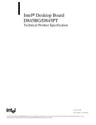
Setting Up<br />
To set up your <strong>Premio</strong> system, simply connect your monitor, the mouse,<br />
the keyboard, and any additional components you want to use to the<br />
system unit.<br />
Follow these easy steps:<br />
1 Attach your monitor’s video cable<br />
Power Connector<br />
to the video connector.<br />
2 Attach the mouse cable to the<br />
Mouse Connector<br />
mouse connector.<br />
Keyboard Connector<br />
USB Connector<br />
3 Attach the keyboard cable to the<br />
keyboard connector.<br />
Serial-1 Connector<br />
Serial-2 Connector<br />
4 Attach the cables for any additional<br />
components, such as a printer,<br />
Parallel Connector<br />
scanner, or modem, to the<br />
respective parallel, serial, or<br />
universal serial bus (USB)<br />
connector, as directed in the<br />
Video Connector<br />
component’s manual.<br />
Sound Card Connectors<br />
5 If your system is equipped for<br />
multimedia, attach your speakers<br />
and microphone to the sound card<br />
connectors.<br />
6 Plug your monitor’s power cord into a power outlet.<br />
7 Attach the female end of the system power cord to the<br />
system unit’s power connector, and then plug the other end<br />
of the cord into a power outlet.<br />
Your <strong>Premio</strong> system is now ready to use. To start the system, turn on your<br />
monitor’s power switch, and then press the system power switch as shown<br />
on the next page.
Switches and Indicators<br />
Mid-tower system<br />
CD ROM Drive<br />
Floppy Drive<br />
Power Switch<br />
Hard Drive<br />
Power Indicator<br />
Reset Button<br />
Getting Started 3<br />
The system unit’s front panel provides access to the CD-ROM and floppy<br />
drives, and to the system’s switches and indicator lights.<br />
The illustration below shows a mid-tower system. If you have a desktop<br />
system, turn to the illustration on the next page.<br />
The CD-ROM drive reads<br />
information on CDs.<br />
The floppy drive reads and<br />
writes information on diskettes.<br />
The power switch turns the<br />
system on and off.<br />
The hard drive indicator lights<br />
when the hard drive is in use.<br />
The power indicator lights<br />
when the system is on.<br />
The reset button restarts the<br />
system.
4 <strong>Premio</strong> System Manual<br />
Desktop system<br />
Reset Button<br />
Hard Drive Indicator<br />
Power Indicator<br />
The reset button restarts the system.<br />
The hard drive indicator lights when the hard drive is in use.<br />
The power indicator lights when the system is on.<br />
The power switch turns the system on and off.<br />
The CD-ROM drive reads information on CDs.<br />
The floppy drive reads and writes information on diskettes.<br />
Power Switch<br />
CD ROM Drive<br />
Floppy Drive
Upgrading<br />
You can upgrade your <strong>Premio</strong> system with:<br />
Expansion cards<br />
More memory<br />
An additional hard drive<br />
To install an upgrade, you must open the system unit. Before<br />
proceeding, read the important cautionary note below. Then follow the<br />
steps on the next page.<br />
Caution! Static discharge can cause permanent damage to internal<br />
electronic components of your computer. Always use the following<br />
precautions when working inside the system unit:<br />
Wear a grounding wrist strap (available at most electronics<br />
stores) when handling electronic components.<br />
Do not remove a component from its antistatic packaging until<br />
you are ready to install it.<br />
Keep one hand in contact with the metal system case.
6 <strong>Premio</strong> System Manual<br />
Opening the System Unit<br />
Mid-tower system<br />
Desktop system<br />
Note: Opening the system unit could affect your warranty. Check with<br />
the dealer where you purchased your system before opening the<br />
system unit.<br />
To open the system unit, follow these steps:<br />
1 Turn off the system and<br />
unplug the power cord.<br />
2 Remove the screws<br />
securing the side panel<br />
(mid-tower) or case<br />
(desktop) at the rear of the<br />
system unit.<br />
3 Slide the side panel or<br />
case up and to the rear,<br />
and remove it.
Installing an Expansion Card<br />
Upgrading 7<br />
To install an expansion card, open the system unit as described on the<br />
previous page. Then follow these steps:<br />
1 Remove the screw<br />
securing the slot bracket<br />
cover for the expansion<br />
slot you want to use. Save<br />
the screw to secure the<br />
expansion card.<br />
2 Insert the expansion card<br />
firmly into the slot,<br />
making sure it is seated<br />
completely.<br />
3 Secure the card with the<br />
saved screw.
8 <strong>Premio</strong> System Manual<br />
Installing a Hard Drive<br />
Mid-tower system<br />
Desktop system<br />
To install a hard drive in your system, follow these steps:<br />
1 Disconnect the hard drive cable and power connector.<br />
2 Remove the two screws securing the drive bay.<br />
3 Slide the bay toward the rear of the system unit to remove it.<br />
4 Insert the new drive into an open position in the bay and secure<br />
it with four screws.<br />
5 Slide the bay back into the system unit and secure it with two<br />
screws.<br />
6 Connect the cables.
Getting Help<br />
Troubleshooting<br />
Your <strong>Premio</strong> system is designed to provide years of trouble-free<br />
performance. If you have a problem with your system, you may wish<br />
to check the information in this section for a quick solution.<br />
Monitor Does Not Work<br />
If your monitor appears not to be working properly:<br />
Check that the monitor’s power cable is securely attached to<br />
the monitor and to an outlet that is receiving power.<br />
Check that the monitor’s video cable is securely attached to the<br />
monitor and to the system unit’s video card connector.<br />
Check that the monitor’s power switch is on.<br />
Adjust the monitor’s brightness and contrast controls.<br />
If possible, substitute another monitor that is in good working<br />
order. If the substitute works, your monitor may need repair or<br />
replacement.
10 <strong>Premio</strong> System Manual<br />
Keyboard Does Not Work<br />
If the NumLock indicator in the upper right corner of the keyboard<br />
does not light when the system powers up, or the keyboard does not<br />
work:<br />
Check that the keyboard cable is securely attached to the<br />
system unit’s keyboard connector.<br />
If possible, substitute another keyboard that is in good working<br />
order. If the substitute works, your keyboard may need<br />
replacement.<br />
Mouse Does Not Work<br />
If your mouse pointer does not move or moves erratically when you<br />
move the mouse:<br />
Check that the mouse cable is securely attached to the mouse<br />
connector on the system unit.<br />
Disassemble the mouse and clean the roller ball.
System Unit Problems<br />
Getting Help 11<br />
The fan inside the system unit should make a low, steady sound<br />
when operating properly.<br />
If the fan is totally silent:<br />
Check that the system power cord is securely attached to the<br />
back of the system unit and to a power outlet. Verify that the<br />
outlet has power.<br />
If possible, substitute another power cord that is in good<br />
working order. If the substitute works, replace your power<br />
cord.<br />
If the fan makes excessive noise:<br />
Turn off the system, open the system unit case, and inspect the<br />
fan for any obstructions.<br />
Turn on the system and listen closely to the fan. If the noise<br />
comes from inside the fan housing, your power supply may<br />
need replacement.<br />
Hard Drive Problems<br />
Your hard drive should make a slight whirring sound when operating<br />
properly.<br />
If the drive is totally silent:<br />
Turn off the system, open the system unit case, and check that<br />
the power cable between the power supply and the hard drive<br />
is securely attached at both ends. If it is, your hard drive may<br />
be defective.<br />
If the hard drive makes excessive noise:<br />
Turn off the system, open the system unit case, and remove the<br />
hard drive power cable connector from the hard drive. Then<br />
turn the system back on. If the noise disappears, your hard<br />
drive may be defective.<br />
If you have more than one hard drive, repeat the same<br />
procedure for each drive.
12 <strong>Premio</strong> System Manual<br />
Technical Support<br />
You can contact <strong>Premio</strong> technical support at the following address:<br />
<strong>Premio</strong> Computer, <strong>Inc</strong>.<br />
918 Radecki Court<br />
City of Industry, CA 91748<br />
Telephone: 626.839.3100<br />
Fax: 626.839.3191<br />
Email: support@premiopc.com<br />
Web page: http://support.premiopc.com<br />
<strong>Premio</strong> on the Internet<br />
<strong>Premio</strong> maintains a web page on the Internet with the latest<br />
information on <strong>Premio</strong> products, updated drivers, answers to<br />
common problems, a troubleshooting guide, and more. Visit our web<br />
page at:<br />
http://www.premiopc.com
Appendix<br />
Warranty Policy<br />
<strong>Premio</strong> Computer, <strong>Inc</strong>. warrants its line of <strong>Premio</strong> ® computer systems to<br />
be free from defects in material and workmanship for a specific warranted<br />
period as stated below, from the date of original purchase from <strong>Premio</strong><br />
Computer, <strong>Inc</strong>. or a <strong>Premio</strong> Computer, <strong>Inc</strong>. authorized reseller. This<br />
warranty is contingent upon proper use of the product in question and<br />
does not cover products which have been modified or which have been<br />
subjected to unusual physical or electrical stress. Warranty for third party<br />
hardware and software, if any, is subject to the third party's warranty<br />
policy. Please refer to the following for length of warranty for <strong>Premio</strong>'s<br />
product line.<br />
<strong>Premio</strong> Product Warranty<br />
Complete <strong>Premio</strong> System with monitor 3 years parts<br />
and labor<br />
<strong>Premio</strong> Barebone (with or without CPU) 2 years parts<br />
and labor<br />
<strong>Premio</strong> Monitor 2 year parts and<br />
labor<br />
<strong>Premio</strong> OEM Component (motherboard, speaker, case,<br />
keyboard, mouse, floppy drive, CD-ROM, etc.)<br />
2 years parts<br />
and labor
14 <strong>Premio</strong> System Manual<br />
Service Under Warranty<br />
If this product fails to be in good working order during the warranty<br />
period (or specific period of time as noted above), <strong>Premio</strong> Computer, <strong>Inc</strong>.<br />
will, at its option, repair or replace the product. Repair parts and/or<br />
replacement products may be either new or reconditioned at <strong>Premio</strong><br />
Computer <strong>Inc</strong>.'s discretion. The limited warranty does not include service<br />
or repair for damage from improper installation, abuse or modifications to<br />
the product not approved in writing by <strong>Premio</strong> Computer, <strong>Inc</strong>. Any<br />
service repair outside the scope of this limited warranty will be at <strong>Premio</strong><br />
Computer, <strong>Inc</strong>.'s or its Authorized Service Provider's rates and terms in<br />
effect. This warranty is valid only within the United States, Puerto Rico,<br />
Canada, Mexico and South America.<br />
Exclusions from Limited Warranty Programs<br />
All other expressed and implied warranties for this product are hereby<br />
disclaimed. If this product is not in good working order as warranted<br />
above, <strong>Premio</strong> Computer's sole and exclusive remedy shall be repair or<br />
replacement as stated above. In no event will <strong>Premio</strong> Computer, <strong>Inc</strong>. be<br />
liable to the customer or any third party for any damages in excess of the<br />
purchase price of the product. This limitation applies to damages of any<br />
kind including any direct or indirect damages, lost profits, lost savings or<br />
other special, incidental or consequential damages. This holds true for<br />
situations even if <strong>Premio</strong> Computer, <strong>Inc</strong>. or an authorized <strong>Premio</strong><br />
representative or dealer has been advised of the possibility of such<br />
damages or of any claim by another party. Some states do not allow the<br />
exclusion or limitation of incidental or consequential damages for some<br />
products, so the above limitation or exclusion may not apply to you.<br />
<strong>Premio</strong> Computer, <strong>Inc</strong>. authorized resellers and service providers/partners<br />
may be changed, added or deleted, without notice or liability. <strong>Premio</strong><br />
Computer, <strong>Inc</strong>. disclaims any authorized resellers and service<br />
provider/partner to the program. This warranty gives you specific legal<br />
rights and you may also have other rights, which may vary from state to<br />
state.
FCC Standards<br />
Appendix 15<br />
This equipment has been tested and found to comply with the limits for a<br />
Class B digital device, pursuant to Part 15 of the FCC Rules. These limits<br />
are designed to provide reasonable protection against harmful interference<br />
in a residential installation. This equipment generates, uses and can<br />
radiate radio frequency energy and, if not installed and used in accordance<br />
with the instructions, may cause harmful interference to radio<br />
communications. However, there is no guarantee that interference will not<br />
occur in a particular installation. If this equipment does cause harmful<br />
interference to radio or television reception, which can be determined by<br />
turning the equipment off and on, the user is encouraged to try to correct<br />
the interference by one or more of the following measures:<br />
Reorient or relocate the receiving antenna.<br />
<strong>Inc</strong>rease the separation between the equipment and receiver.<br />
Connect the equipment into an outlet on a circuit different from that<br />
to which the receiver is connected.<br />
Consult the dealer or an experienced radio/TV technician for help.
16 <strong>Premio</strong> System Manual<br />
Important Safety Instructions<br />
These instructions are provided by Underwriters Laboratories, <strong>Inc</strong>.<br />
1. Read all of these instructions and save them for later reference.<br />
2. Follow all warnings and instructions marked on the product.<br />
3. Unplug this product from the wall outlet before cleaning. Do not<br />
use liquid or aerosol cleaners. Use a damp cloth for cleaning.<br />
4. Do not use this product near water.<br />
5. Do not place this product on an unstable cart, stand or table. The<br />
product may fall, causing serious damage to the product.<br />
6. Slots and openings on the cabinet and the back or bottom are<br />
provided for ventilation. To ensure reliable operation of the product<br />
and to protect it from overheating, do not block or cover these<br />
openings. The openings should never be blocked by placing the<br />
product on a bed, sofa, rug or other similar surface. This product<br />
should never be placed near or over a radiator or heat register. This<br />
product should not be placed in a built-in installation unless proper<br />
ventilation is provided.<br />
7. This product should be operated from the type of power source<br />
indicated on the marking label. If you are not sure of the type of<br />
power available, consult your dealer or local power company.<br />
8. This product is equipped with a 3-wire grounding-type plug, a plug<br />
having a third (grounding) pin. This plug will only fit into a<br />
grounding-type power outlet. This is a safety feature. If you are<br />
unable to insert the plug into the outlet, contact your electrician to<br />
replace your obsolete outlet. Do not defeat the safety purpose of the<br />
grounding-type plug.<br />
9. Do not allow anything to rest on the power cord. Do not locate this<br />
product where the cord will be walked on.<br />
10. If an extension cord is used with this product, make sure that the<br />
total of the ampere ratings on the products plugged into the<br />
extension cord do not exceed the extension cord ampere rating.<br />
Also, make sure that the total of all products plugged into the wall<br />
outlet does not exceed 15 amperes.<br />
11. Never push objects of any kind into this product through cabinet<br />
slots as they may touch dangerous voltage points or short out parts
Appendix 17<br />
that could result in a risk of fire or electric shock. Never spill liquid<br />
of any kind on the product.<br />
12. Except as explained elsewhere in this manual, don't attempt to<br />
service this product yourself. Opening and removing those covers<br />
that are marked “Do Not Remove” may expose you to dangerous<br />
voltage points or other risks. Refer all servicing on those<br />
compartments to service personnel.<br />
13. Unplug this product from the wall outlet and refer servicing to<br />
qualified service personnel under the following conditions:<br />
A. When the power cord or plug is damaged or frayed.<br />
B. If liquid has been spilled into the product.<br />
C. If the product has been exposed to rain or water.<br />
D. If the product does not operate normally when the operating<br />
instructions are followed. Adjust only those controls that are<br />
covered by the operating instructions since improper<br />
adjustment of other controls may result in damage and will<br />
often require extensive work by a qualified technician to<br />
restore the product to normal operation.<br />
E. If the product has been dropped or the cabinet has been<br />
damaged.<br />
F. If the product exhibits a distinct change in performance,<br />
indicating a need for service.
Chapter 1<br />
INTRODUCTION<br />
1-1<br />
INTRODUCTION<br />
INTRODUCTION<br />
INTRODUCTION<br />
The MS-6337 Lite ATX mainboard is a high-performance computer<br />
mainboards based on Intel ® 815EP chipset. The MS-6337 Lite is optimized to<br />
support the Intel ® Pentium ® III (FC-PGA) and VIA Cynix III processors for<br />
high-end business/personal desktop markets.<br />
The Intel 815EP chipset contains two components: the 82815EP<br />
Memory Controller Hub (MCH) and the 82801BA I/O Controller Hub 2<br />
(ICH2). The MCH integrates a 66/100/133-MHz, P6 family system bus<br />
controller , AGP (2X/4X) discrete graphics card, 100/133-MHz SDRAM<br />
controller, and a high speed accelerated hub architecture interface for<br />
communication with the ICH2. The ICH2 integrates an UltraATA/100<br />
controller, 2 USB host controllers with a total of 4 ports, LPC interface<br />
controller, FWH interface controller, PCI interface controller, AC’97 digital<br />
link, integrated LAN controller, and a hub interface for communication with<br />
the MCH.
CHAPTER CHAPTER 1<br />
1<br />
Mainboard Features<br />
CPU<br />
l Support Socket370 for Intel ® Pentium ® III(FC-PGA)/VIA Cynix III<br />
processor.<br />
l Support 500MHz, 550MHz, 600MHz, 633MHz, 667MHz, 700MHz, 733MHz,<br />
800MHz, 866MHz, 933MHz, and 1GHz<br />
Chipset<br />
l Intel ® 815EP chipset. (544 BGA)<br />
- AGP 4x/2x universal slot<br />
- Support 66/100/133MHz FSB<br />
l Intel ® ICH2 chipset. (241 BGA)<br />
- AC’97 Audio support<br />
- 2 full IDE channels, up to ATA100<br />
- Low pin count interface for SIO<br />
- 2 USB host controller/4USB ports<br />
Main Memory<br />
l Support three 168-pin DIMM sockets.<br />
l Support a maximum memory size of 512MB SDRAM.<br />
Slots<br />
l One CNR (Communication Network Riser).<br />
l One AGP (Accelerated Graphics Port) 4x slot<br />
l Six PCI 2.2 32-bit Master PCI Bus slots. All PCI slots can be used as<br />
master.<br />
l Support 3.3v/5v PCI bus Interface.<br />
On-Board IDE<br />
l An IDE controller on the ICH2 chipset provides IDE HDD/CD-ROM with<br />
PIO, Bus Master and Ultra DMA 66/100 operation modes.<br />
l Can connect up to four IDE devices.<br />
1- 2
On-Board Peripherals<br />
l On-Board Peripherals include:<br />
- 1 floppy port supports 2 FDD with 360K, 720K, 1.2M,<br />
1.44M and 2.88Mbytes.<br />
- 2 serial ports (COMA/COMB)<br />
- 1 parallel port supports SPP/EPP/ECP mode<br />
- 2 USB ports<br />
- 1 Audio/Game Port<br />
Audio<br />
l ICH2 chip integrated<br />
1-3<br />
INTRODUCTION<br />
INTRODUCTION<br />
INTRODUCTION<br />
BIOS<br />
l The mainboard BIOS provides “Plug & Play” BIOS which detects the<br />
peripheral devices and expansion cards of the board automatically.<br />
l The mainboard provides a Desktop Management Interface(DMI) function<br />
which records your mainboard specifications.<br />
Dimension<br />
l ATX Form Factor<br />
Mounting<br />
l 6 mounting holes.
CHAPTER CHAPTER 1<br />
1<br />
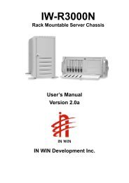
Mainboard Layout<br />
Top:<br />
mouse<br />
Bottom:<br />
keyboard<br />
USB<br />
Top: Port 1<br />
Bottom:<br />
Port 2<br />
Top: LPT<br />
Bottom:<br />
COM A<br />
COM B<br />
Top: Midi/<br />
Game Port<br />
Bottom:<br />
Line-Out<br />
Line-In<br />
Mic<br />
BATT<br />
+<br />
BIOS<br />
PSFAN<br />
J2<br />
CD_IN<br />
AUX_IN<br />
MDM_IN<br />
ATX<br />
Power Supply<br />
CNR<br />
PCI SLOT 1<br />
PCI SLOT 2<br />
Intel<br />
815EP<br />
Chipset<br />
AGP Slot<br />
PCI SLOT 3<br />
PCI SLOT 4<br />
PCI SLOT 5<br />
PCI SLOT 6<br />
MS-6337 Lite ATX Mainboard<br />
1- 4<br />
Socket 370<br />
DIMM 1<br />
DIMM 2<br />
SYSFAN<br />
Intel<br />
FW82801BA<br />
JFP1<br />
DIMM 3<br />
SW1<br />
JWOL1<br />
J7<br />
CPUFAN<br />
IDE2<br />
IDE1 FDD<br />
JMDM1<br />
JBAT2
Jumpers & Connectors Description<br />
SW1<br />
J2<br />
JMDM1<br />
JWOL1<br />
JBAT2 3<br />
JFP1<br />
Keylock<br />
1<br />
3<br />
1<br />
5<br />
1<br />
1-5<br />
INTRODUCTION<br />
INTRODUCTION<br />
INTRODUCTION<br />
Overclocking is operating a CPU/Processor beyond its<br />
specified frequency. SW1 jumper is used for<br />
overclocking.<br />
This is used to check the AGP chipset temperature on AGP<br />
card. The J2 is a 2-pin connector which can be inserted with<br />
a 20cm length thermistor. It is located near the chipset<br />
heatsink that monitors the chipset temperature. The BIOS<br />
setup for “TOP TECH III” should be set to enabled (option).<br />
The JMDM1 connector is for use with Modem add-on card<br />
that supports the Modem Wake Up function.<br />
The JWOL1 connector is for use with LAN add-on cards<br />
that supports Wake Up on LAN function. To use this<br />
function, you need to set the “Wake-Up on LAN” to enable<br />
at the BIOS Power Management Setup.<br />
A battery must be used to retain the mainboard<br />
configuration in CMOS RAM. Short 1-2 pins of JBAT2 to<br />
store the CMOS data.<br />
+<br />
Speaker<br />
Buzzer<br />
(short pin) 14 15<br />
+<br />
Reset<br />
Switch<br />
HDD<br />
Dual<br />
LED Power<br />
Color LED Power<br />
LED<br />
Switch<br />
Single<br />
Color LED<br />
The Keylock, Power Switch, Reset Switch,<br />
Power LED, Speaker and HDD LED are all<br />
connected to the JFP1 connector block.<br />
There are two types of LED that you can<br />
use: 3-pin single color LED or 2-pin dual<br />
color LED(ACPI request).<br />
a. 3 pin single color LED connect<br />
to pin 4, 5, & 6. This LED will lit<br />
when the system is on.<br />
b. 2 pin dual color LED connect to<br />
pin 5 & 6.
CHAPTER CHAPTER 1<br />
1<br />
J7<br />
Green Switch<br />
1<br />
Buzzer/SPKR<br />
11<br />
Chassis<br />
Intrusion<br />
Reserved<br />
15<br />
IR IRTX<br />
Reserved<br />
IRRX Onboard Codec Enable<br />
J7 is a Front Panel connector.<br />
Pin Definition:<br />
11-13 pin (optional)<br />
Short 11-13 pin to disable Onboard Codec.<br />
13-15 pin (optional)<br />
Short 13-15 pin to enable Onboard Codec.<br />
Speaker Output<br />
Short 6-8 pin to activate AC97_SPKR<br />
Short 8-10 pin to activate onboard Buzzer.<br />
1- 6
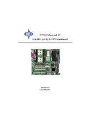
Back Panel<br />
1<br />
2<br />
1<br />
2<br />
3<br />
3<br />
Mouse Connector<br />
Pin6<br />
NC<br />
Pin4<br />
VCC<br />
Pin2<br />
NC<br />
Keyboard Connector<br />
Pin6<br />
NC<br />
Pin4<br />
VCC<br />
Pin2<br />
NC<br />
USB Ports<br />
1 2 3 4<br />
PIN SIGNAL<br />
1 VCC<br />
2 -Data<br />
3 +Data<br />
4 GND<br />
COM A COM B<br />
Pin5<br />
Mouse Clock<br />
Pin3<br />
GND<br />
Pin1<br />
Mouse DATA<br />
Pin5<br />
KBD Clock<br />
Pin3<br />
GND<br />
Pin1<br />
KBD DATA<br />
USB Port 1<br />
USB Port 2<br />
LPT 1<br />
1-7<br />
4<br />
4 Joystick/MIDI<br />
5<br />
Audio Ports<br />
Line<br />
Out<br />
5<br />
Line<br />
In<br />
MIC<br />
INTRODUCTION<br />
INTRODUCTION<br />
INTRODUCTION
CHAPTER CHAPTER 1<br />
1<br />
1- 8
Chapter 2<br />
AWARD ® BIOS SETUP<br />
2-1<br />
AWARD AWARD®<br />
BIOS BIOS SETUP<br />
SETUP<br />
Award ® BIOS ROM has a built-in Setup program that allows users to modify<br />
the basic system configuration. This type of information is stored in<br />
battery-backed RAM (CMOS RAM), so that it retains the Setup information<br />
when the power is turned off.
CHAPTER CHAPTER 2<br />
2<br />
Entering Entering Setup Setup<br />
Setup<br />
Power on the computer and press immediately to allow you to<br />
enter Setup. The other way to enter Setup is to power on the computer.<br />
When the below message appears briefly at the bottom of the screen during<br />
the POST (Power On Self Test), press key or simultaneously press<br />
, , and keys.<br />
TO ENTER SETUP BEFORE BOOT, PRESS <br />
OR KEY<br />
If the message disappears before you respond and you still wish to<br />
enter Setup, restart the system to try again by turning it OFF then ON or<br />
pressing the “RESET” button on the system case. You may also restart by<br />
simultaneously pressing , , and keys. If you do not<br />
press the keys at the correct time and the system does not boot, an error<br />
message will be displayed and you will again be asked to,<br />
PRESS TO CONTINUE, <br />
OR TO ENTER SETUP<br />
Getting Getting Help<br />
Help<br />
Main Menu<br />
The on-line description of the highlighted setup function is displayed<br />
at the bottom of the screen.<br />
Status Page Setup Menu/Option Page Setup Menu<br />
Press F1 to pop up a small help window that describes the appropriate<br />
keys to use and the possible selections for the highlighted item. To exit<br />
the Help Window, press .<br />
2- 2
The The Main Main Menu<br />
Menu<br />
STANDARD CMOS Feature<br />
Advanced BIOS Feature<br />
Advanced Chipset Feature<br />
Integrated Peripherals<br />
Power Management Setup<br />
PnP/PCI Configurations<br />
PC Health Status<br />
2-3<br />
AWARD AWARD®<br />
BIOS BIOS SETUP<br />
SETUP<br />
Once you enter Award ® BIOS CMOS Setup Utility, the Main Menu (Figure<br />
1) will appear on the screen. The Main Menu allows you to select from<br />
twelve setup functions and two exit choices. Use arrow keys to select<br />
among the items and press to accept or enter the sub-menu.<br />
CMOS Setup Utility - Copyright(C) 1984-2000<br />
Esc : Quit<br />
F10 : Save & Exit Setup<br />
Frequency/Voltage Control<br />
Load Fail-Safe Defaults<br />
Load Optimized Defaults<br />
Set Supervisor Password<br />
Set User Password<br />
Save & Exit Setup<br />
Exit Without Saving<br />
↑ ↓ → ← : Select Item<br />
(Shift)F2 : Change Color<br />
Time, Date, Hard Disk Type...
CHAPTER CHAPTER 2<br />
2<br />
Standard Standard CMOS CMOS Setup Setup<br />
Setup<br />
The items in Standard CMOS Setup Menu are divided into 10<br />
categories. Each category includes no, one or more than one setup items.<br />
Use the arrow keys to highlight the item and then use the or<br />
keys to select the value you want in each item.<br />
CMOS Setup Utility - Copyright(C) 1984-2000 Award Software<br />
Standard CMOS Setup<br />
Date(mm:dd:yy): Fri, Feb 28,1999<br />
Time(hh:mm:ss): 00:00:00<br />
IDE Primary Master Press Enter 2557MB<br />
IDE Primary Slave Press Enter None<br />
IDE Secondary Master Press Enter None<br />
IDE Secondary Slave Press Enter None<br />
Drive A 1.44M, 3.5in.<br />
Drive B None<br />
Video EGA/VGA<br />
Halt On All Errors<br />
Based Memory 640K<br />
Extended Memory 64512K<br />
Total Memory 65536K<br />
2- 4<br />
Item Help<br />
Menu Level ><br />
↑ ↓ → ← Move Enter:Select +/-/PU/PD:Value F10:Save ESC:Exit F1:General Help<br />
F5:Previous Values F6:Fail-safe defaults F7:Optimized Defaults
Advanced Advanced BIOS BIOS Features<br />
Features<br />
Anti-Virus Protection Disabled<br />
CPU Internal Cache Enabled<br />
External Cache Enabled<br />
CPU L2 Cache ECC Checking Enabled<br />
Processor Number Feature Enabled<br />
Quick Power On Self Test Enabled<br />
First Boot device Floppy<br />
Second Boot device HDD-0<br />
Third Boot device LS120<br />
Fourth Boot device Disabled<br />
Swap Floppy Drive Disabled<br />
Boot Up Floppy Seek Enabled<br />
Boot Up Numlock Status On<br />
Gate A20 Option Fast<br />
Typematic Rate Setting Disabled<br />
Typematic Rate (Chars/Sec) 6<br />
Typematic Delay (Msec) 250<br />
Security Option Setup<br />
OS Select for DRAM > 64MB Non-OS2<br />
HDD S.M.A.R.T. Capability Disabled<br />
Report No FDD for Win 95 No<br />
Full Screen LOGO Show Enabled<br />
2-5<br />
AWARD AWARD®<br />
BIOS BIOS SETUP<br />
SETUP<br />
CMOS Setup Utility - Copyright(C) 1984-2000 Award Software<br />
Advanced BIOS Features<br />
Item Help<br />
Menu Level ><br />
↑ ↓ → ← Move Enter:Select +/-/PU/PD:Value F10:Save ESC:Exit F1:General Help<br />
F5:Previous Values F6:Fail-safe defaults F7:Optimized Defaults
CHAPTER CHAPTER 2<br />
2<br />
Advanced Advanced Chipset Chipset Features<br />
Features<br />
The Advanced Chipset Features Setup option is used to change the<br />
values of the chipset registers. These registers control most of the system<br />
options in the computer.<br />
Choose the “ADVANCED CHIPSET FEATURES” from the Main<br />
Menu and the following screen will appear.<br />
CMOS Setup Utility - Copyright(C) 1984-2000 Award Software<br />
Advanced Chipset Features<br />
SDRAM CAS Latency Time Auto<br />
SDRAM Cycle Time Tras/Trc 7/9<br />
SDRAM RAS-to-CAS Delay 3<br />
SDRAM RAS Precharge Time 3<br />
System BIOS Cacheable Disabled<br />
Video BIOS Cacheable Disabled<br />
Memory Hole at 15M-16M Disabled<br />
CPU Latency Timer Enabled<br />
Delayed Transaction Enabled<br />
AGP Graphics Aperture Size 64MB<br />
System Memory Frequency Auto<br />
On-Chip Video Window Size 64MB<br />
*Onboard Display Cache Setting*<br />
CAS# Latency 3<br />
Paging Mode Control Open<br />
RAS-to-CAS Override by CAS#LT<br />
RAS# Timing Fast<br />
RAS# Precharge Timing Fast<br />
Note: Change these settings only if you are familiar with the chipset.<br />
2- 6<br />
Item Help<br />
Menu Level ><br />
↑ ↓ → ← Move Enter:Select +/-/PU/PD:Value F10:Save ESC:Exit F1:General Help<br />
F5:Previous Values F6:Fail-safe defaults F7:Optimized Defaults
Integrated Integrated Integrated Peripherals<br />
Peripherals<br />
OnChip Primary PCI IDE Enabled<br />
OnChip Secondary PCI IDE Enabled<br />
IDE Primary Master PIO Auto<br />
IDE Primary Slave PIO Auto<br />
IDE Secondary Master PIO Auto<br />
IDE Secondary Slave PIO Auto<br />
IDE Primary Master UDMA Auto<br />
IDE Primary Slave UDMA Auto<br />
IDE Secondary Master UDMA Auto<br />
IDE Secondary Slave UDMA Auto<br />
USB Controller Enabled<br />
USB Keyboard Support Disabled<br />
Init Display First PCI Slot<br />
AC97 Audio Auto<br />
AC97 Modem Auto<br />
IDE HDD Block Mode Enabled<br />
Keyboard Power On Disabled<br />
POWER ON Function Button Only<br />
KB Power On Password Enter<br />
Hot Key Power On Ctrl-F1<br />
Onboard FDC Controller Enabled<br />
Onboard Serial Port 1 3F8/IRQ4<br />
Onboard Serial Port 2 2F8/IRQ3<br />
2-7<br />
AWARD AWARD®<br />
BIOS BIOS SETUP<br />
SETUP<br />
CMOS Setup Utility - Copyright(C) 1984-2000 Award Software<br />
Integrated Peripherals<br />
Item Help<br />
Menu Level ><br />
↑ ↓ → ← Move Enter:Select +/-/PU/PD:Value F10:Save ESC:Exit F1:General Help<br />
F5:Previous Values F6:Fail-safe defaults F7:Optimized Defaults<br />
UART Mode Select Normal<br />
RxD, TxD Active Hi, Lo<br />
IR Transmition Delay Enabled<br />
UR2 Duplex Mode Half<br />
USE IR Pins IR-Rx2Tx2<br />
Onboard Parallel Port 378/IRQ7<br />
Parallel Port Mode SPP<br />
EPP Mode Select EPP 1.7<br />
ECP Mode use UDMA 3<br />
PWRON After PWR-Fail Off<br />
Game Port Address 201<br />
Midi Port Address 290<br />
Midi Port IRQ 10<br />
Power Status LED Single
CHAPTER CHAPTER 2<br />
2<br />
Power Power Power Management Management Management Setup Setup<br />
Setup<br />
The Power Management Setup allows you to configure you system<br />
to most effectively save energy while operating in a manner consistent with<br />
your own style of computer use.<br />
CMOS Setup Utility - Copyright(C) 1984-2000 Award Software<br />
Power Management Setup<br />
ACPI Function Enabled<br />
ACPI Suspend Type S1(POS)<br />
Power Management User Define<br />
Video Off Method DPMS<br />
Video Off In Suspend Yes<br />
Suspend Type Stop Grant<br />
Modem Use IRQ 3<br />
Suspend Mode Disabled<br />
HDD Power Down Disabled<br />
Soft-Off by PWR-BTTN Instant-Off<br />
Wake-Up by PCI Card Disabled<br />
Power On by Ring Enabled<br />
Wake-Up on LAN Enabled<br />
USB KB Wake-Up From S3 Disabled<br />
CPU Thermal-Throtting 50.0%<br />
Resume By Alarm Disabled<br />
Date(of Month) Alarm 0<br />
Date(hh:mm:ss) 0 0 0<br />
**Reload Global Timer Events**<br />
Primary IDE 0 Disabled<br />
Primary IDE 1 Disabled<br />
Secondary IDE 0 Disabled<br />
Secondary IDE 1 Disabled<br />
FDD, COM, LPT Port Disabled<br />
PCI PIRQ[A-D]# Disabled<br />
2- 8<br />
Item Help<br />
Menu Level ><br />
↑ ↓ → ← Move Enter:Select +/-/PU/PD:Value F10:Save ESC:Exit F1:General Help<br />
F5:Previous Values F6:Fail-safe defaults F7:Optimized Defaults
PnP/PCI PnP/PCI Configuration Configuration Setup Setup<br />
Setup<br />
2-9<br />
AWARD AWARD®<br />
BIOS BIOS SETUP<br />
SETUP<br />
This section describes configuring the PCI bus system. PCI, or Personal<br />
Computer Interconnect, is a system which allows I/O devices to operate at<br />
speeds nearing the speed the CPU itself uses when communicating with its<br />
own special components. This section covers some very technical items<br />
and it is strongly recommended that only experienced users should make<br />
any changes to the default settings.<br />
CMOS Setup Utility - Copyright(C) 1984-2000 Award Software<br />
PnP/PCI Configuration Setup<br />
PNP OS Installed No<br />
Reset Configuration Data Disabled<br />
Resources Controlled By Auto<br />
IRQ Resources Press Enter<br />
DMA Resources Press Enter<br />
PCI/VGA Palette Snoop Disabled<br />
INT Pin 1 Assignment Auto<br />
INT Pin 2 Assignment Auto<br />
INT Pin 3 Assignment Auto<br />
INT Pin 4 Assignment Auto<br />
Item Help<br />
Menu Level ><br />
↑ ↓ → ← Move Enter:Select +/-/PU/PD:Value F10:Save ESC:Exit F1:General Help<br />
F5:Previous Values F6:Fail-safe defaults F7:Optimized Defaults
CHAPTER CHAPTER 2<br />
2<br />
PC PC Health Health Status<br />
Status<br />
This section shows the Status of your CPU, Fan, Warning for overall system<br />
status.<br />
CMOS Setup Utility - Copyright(C) 1984-2000 Award Software<br />
PC Health Status<br />
CPU Warning Temperature Disabled<br />
Current System Temp 39 0 C/102 0 F<br />
Current CPU Temperature 66 0 C/150 0 F<br />
Current Top Tech. III Temp. 32 0 C/89 0 F<br />
Current System Fan 0RPM<br />
Current Power Fan 0RPM<br />
Current CPU FAN 5532RPM<br />
Vcore 1.96V<br />
VTT 1.48V<br />
3.3V 3.24V<br />
+5V 4.89V<br />
+12V 11.79V<br />
-12V 12.19V<br />
-5V -4.53V<br />
VBAT(V) 3.10V<br />
5VSB(V) 5.37V<br />
Chassis Intrusion Detect Disabled<br />
Shutdown Temperature Disabled<br />
2- 10<br />
Item Help<br />
Menu Level ><br />
↑ ↓ → ← Move Enter:Select +/-/PU/PD:Value F10:Save ESC:Exit F1:General Help<br />
F5:Previous Values F6:Fail-safe defaults F7:Optimized Defaults
Frequency/V<br />
Frequency/Voltage Frequency/V oltage Control<br />
Control<br />
This section is for setting CPU Frequency/Voltage Control.<br />
Auto Detect DIMM/PCI Clk Enabled<br />
Spread Spectrum Enabled<br />
Clock By Slight Adjust 66<br />
CPU Internal Freq Will Be 198 Mhz<br />
CPU Clock Ratio Auto<br />
Vcore Adjust 1.30V<br />
(May be dangerous if Vcore Adjust ovr 10%)<br />
Vio Voltage Adust 3.4V<br />
2-11<br />
AWARD AWARD®<br />
BIOS BIOS SETUP<br />
SETUP<br />
CMOS Setup Utility - Copyright(C) 1984-2000 Award Software<br />
Frequency/Voltage Control<br />
Item Help<br />
Menu Level ><br />
↑ ↓ → ← Move Enter:Select +/-/PU/PD:Value F10:Save ESC:Exit F1:General Help<br />
F5:Previous Values F6:Fail-safe defaults F7:Optimized Defaults
CHAPTER CHAPTER 2<br />
2<br />
Load Load Load Fail-Safe/Optimized Fail-Safe/Optimized Defaults Defaults<br />
Defaults<br />
Load Fail-Safe Defaults<br />
When you press on this item, you get a confirmation dialog box<br />
with a message similar to:<br />
Load Fail-Safe Defaults (Y/N) ? N<br />
Pressing ‘Y’ loads the BIOS default values for the most stable, minimalperformance<br />
system operations.<br />
Load Optimized Defaults<br />
When you press on this item, you get a confirmation dialog box<br />
with a message similar to:<br />
Load Optimized Defaults (Y/N) ? N<br />
Pressing ‘Y’ loads the default values that are factory settings for optimal<br />
performance system operations.<br />
2- 12
Set Set Set Supervisor/User Supervisor/User Password Password<br />
Password<br />
2-13<br />
AWARD AWARD®<br />
BIOS BIOS SETUP<br />
SETUP<br />
You can set either supervisor or user password, or both of them. The<br />
differences are:<br />
Supervisor password : Can enter and change the options of the setup<br />
menus.<br />
User password : Can only enter but do not have the right to change<br />
the options of the setup menus. When you select<br />
this function, the following message will appear at<br />
the center of the screen to assist you in creating a<br />
password.<br />
ENTER PASSWORD:<br />
Type the password, up to eight characters in length, and press . The<br />
password typed now will clear any previously entered password from CMOS<br />
memory. You will be asked to confirm the password. Type the password again<br />
and press . You may also press to abort the selection and not<br />
enter a password.<br />
To disable a password, just press when you are prompted to enter the<br />
password. A message will confirm the password will be disabled. Once the<br />
password is disabled, the system will boot and you can enter Setup freely.<br />
PASSWORD DISABLED.<br />
When a password has been enabled, you will be prompted to enter it every<br />
time you try to enter Setup. This prevents an unauthorized person from changing<br />
any part of your system configuration.
CHAPTER CHAPTER 2<br />
2<br />
Additionally, when a password is enabled, you can also require the BIOS to<br />
request a password every time your system is rebooted. This would prevent<br />
unauthorized use of your computer.<br />
You determine when the password is required within the BIOS Features<br />
Setup Menu and its Security option. If the Security option is set to<br />
“System”, the password will be required both at boot and at entry to Setup.<br />
If set to “Setup”, prompting only occurs when trying to enter Setup.<br />
2- 14