MS-6507E (v1.X) Micro ATX Mainboard - Premio, Inc.
MS-6507E (v1.X) Micro ATX Mainboard - Premio, Inc.
MS-6507E (v1.X) Micro ATX Mainboard - Premio, Inc.

You also want an ePaper? Increase the reach of your titles
YUMPU automatically turns print PDFs into web optimized ePapers that Google loves.
<strong>MS</strong>I<br />
MICRO-STAR INTERNATIONAL<br />
<strong>MS</strong>-<strong>6507E</strong> (<strong>v1.X</strong>) <strong>Micro</strong> <strong>ATX</strong> <strong>Mainboard</strong><br />
Version 1.0<br />
G52-MA00561<br />
i
Manual Rev: 1.0<br />
Release Date: March 2002<br />
FCC-B Radio Frequency Interference Statement<br />
This equipment has been tested and found to comply with the limits for a class<br />
B digital device, pursuant to part 15 of the FCC rules. These limits are designed<br />
to provide reasonable protection against harmful interference when the equipment<br />
is operated in a commercial environment. This equipment generates, uses<br />
and can radiate radio frequency energy and, if not installed and used in accordance<br />
with the instruction manual, may cause harmful interference to radio<br />
communications. Operation of this equipment in a residential area is likely to<br />
cause harmful interference, in which case the user will be required to correct<br />
the interference at his own expense.<br />
Notice 1<br />
The changes or modifications not expressly approved by the party responsible<br />
for compliance could void the user’s authority to operate the equipment.<br />
Notice 2<br />
Shielded interface cables and A.C. power cord, if any, must be used in order to<br />
comply with the emission limits.<br />
VOIR LA NOTICE D’INSTALLATION AVANT DE RACCORDER AU<br />
RESEAU.<br />
<strong>Micro</strong>-Star International <strong>MS</strong>-<strong>6507E</strong><br />
Tested to comply<br />
with FCC Standard<br />
For Home or Office Use<br />
ii
Edition<br />
March 2002<br />
Copyright Notice<br />
The material in this document is the intellectual property of MICRO-STAR<br />
INTERNATIONAL. We take every care in the preparation of this document,<br />
but no guarantee is given as to the correctness of its contents. Our products<br />
are under continual improvement and we reserve the right to make changes<br />
without notice.<br />
Trademarks<br />
All trademarks are the properties of their respective owners.<br />
Intel ® and Pentium ® are registered trademarks of Intel Corporation.<br />
PS/2 and OS ® /2 are registered trademarks of International Business Machines<br />
Corporation.<br />
Windows ® 95/98/2000/NT/XP are registered trademarks of <strong>Micro</strong>soft<br />
Corporation.<br />
Netware ® is a registered trademark of Novell, <strong>Inc</strong>.<br />
Award ® is a registered trademark of Phoenix Technologies Ltd.<br />
AMI ® is a registered trademark of American Megatrends <strong>Inc</strong>.<br />
Revision History<br />
Revision Revision History Date<br />
V1.0 First release March 2002<br />
iii
Safety Instructions<br />
1. Always read the safety instructions carefully.<br />
2. Keep this User’s Manual for future reference.<br />
3. Keep this equipment away from humidity.<br />
4. Lay this equipment on a reliable flat surface before setting it up.<br />
5. The openings on the enclosure are for air convection hence protects the<br />
equipment from overheating. DO NOT COVER THE OPENINGS.<br />
6. Make sure the voltage of the power source and adjust properly 110/220V<br />
before connecting the equipment to the power inlet.<br />
7. Place the power cord such a way that people can not step on it. Do not<br />
place anything over the power cord.<br />
8. Always Unplug the Power Cord before inserting any add-on card or module.<br />
9. All cautions and warnings on the equipment should be noted.<br />
10. Never pour any liquid into the opening that could damage or cause electrical<br />
shock.<br />
11. If any of the following situations arises, get the equipment checked by a<br />
service personnel:<br />
The power cord or plug is damaged<br />
Liquid has penetrated into the equipment<br />
The equipment has been exposed to moisture<br />
The equipment has not work well or you can not get it work according<br />
to User’s Manual.<br />
The equipment has dropped and damaged<br />
If the equipment has obvious sign of breakage<br />
12. DO NOT LEAVE THIS EQUIPMENT IN AN ENVIRONMENT<br />
UNCONDITIONED, STORAGE TEMPERATURE ABOVE 60 0 C (140 0 F), IT<br />
MAY DAMAGE THE EQUIPMENT.<br />
CAUTION: Danger of explosion if battery is incorrectly replaced.<br />
Replace only with the same or equivalent type recommended by the<br />
manufacturer.<br />
iv
CONTENTS<br />
Chapter 1. Getting Started ........................................................................ 1-1<br />
<strong>Mainboard</strong> Specification ...................................................................... 1-2<br />
<strong>Mainboard</strong> Layout ............................................................................... 1-4<br />
Quick Components Guide .................................................................... 1-5<br />
Key Features ........................................................................................ 1-6<br />
<strong>MS</strong>I Special Features ........................................................................... 1-7<br />
PC Alert III ................................................................................. 1-7<br />
Chapter 2. Hardware Setup ....................................................................... 2-1<br />
Central Processing Unit: CPU .............................................................. 2-2<br />
CPU Installation Procedures ......................................................... 2-2<br />
Installing the CPU Fan .................................................................. 2-3<br />
CPU Core Speed Derivation Procedure ......................................... 2-4<br />
Memory ................................................................................................ 2-5<br />
Introduction to DDR SDRAM ....................................................... 2-5<br />
DDR Module Combination ............................................................ 2-6<br />
Installing DDR Modules ............................................................... 2-6<br />
Power Supply ....................................................................................... 2-7<br />
<strong>ATX</strong> 20-Pin Power Connector ....................................................... 2-7<br />
<strong>ATX</strong> 12V Power Connector: JPW1 ................................................ 2-7<br />
Back Panel ............................................................................................ 2-8<br />
Mouse Connector ......................................................................... 2-8<br />
Keyboard Connector ..................................................................... 2-9<br />
USB Connectors ............................................................................ 2-9<br />
Serial Port Connector: COM A & COM B ................................... 2-10<br />
Joystick/Midi Connectors ........................................................... 2-10<br />
Audio Port Connectors ............................................................... 2-10<br />
Parallel Port Connector ................................................................ 2-11<br />
LAN Jack (RJ-45) ......................................................................... 2-12<br />
v
Connectors ......................................................................................... 2-13<br />
Floppy Disk Drive Connector: FDD1........................................... 2-13<br />
Hard Disk Connectors: IDE1 & IDE2 ........................................... 2-14<br />
CD-In Connector: JCD1 ............................................................... 2-15<br />
Aux Line-In Connector: JAUX1 .................................................. 2-15<br />
Modem-In Connector: JPHN1 ..................................................... 2-15<br />
Fan Power Connectors: C_FAN1/S_FAN1 .................................. 2-16<br />
Chassis Intrusion Switch Connector: JCI1 .................................. 2-17<br />
IrDA Infrared Module Header: JIR1 ............................................ 2-17<br />
Wake On Ring Connector: JMDM1 ............................................. 2-18<br />
Wake On LAN Connector: JWOL1 .............................................. 2-18<br />
SPDIF Connector: JSP1 ............................................................... 2-19<br />
Front Panel Audio Connector: JAUD1 ........................................ 2-20<br />
Modem Connector: MC1 ............................................................. 2-21<br />
Front Panel Connectors: JFP1 & JFP2 ......................................... 2-22<br />
Front USB Connector: JUSB1 or JUSB2 ...................................... 2-23<br />
Jumpers .............................................................................................. 2-24<br />
Clear CMOS Jumper: JBAT1 ........................................................ 2-24<br />
Slots ................................................................................................... 2-25<br />
AGP (Accelerated Graphics Port) Slot ......................................... 2-25<br />
PCI Slots ...................................................................................... 2-25<br />
CNR (Communication Network Riser) ......................................... 2-25<br />
PCI Interrupt Request Routing .................................................... 2-26<br />
Chapter 3. AWARD® BIOS Setup ............................................................ 3-1<br />
Entering Setup...................................................................................... 3-2<br />
Control Keys ................................................................................. 3-2<br />
Getting Help .................................................................................. 3-3<br />
The Main Menu ................................................................................... 3-4<br />
Standard CMOS Features .................................................................... 3-6<br />
vi
Advanced BIOS Features .................................................................... 3-8<br />
Advanced Chipset Features............................................................... 3-12<br />
Integrated Peripherals ........................................................................ 3-14<br />
Power Management Setup ................................................................. 3-18<br />
PNP/PCI Configurations ..................................................................... 3-22<br />
PC Health Status ................................................................................ 3-24<br />
Frequency/Voltage Control ................................................................ 3-25<br />
Load Fail-Safe/Optimized Defaults ..................................................... 3-27<br />
Set Supervisor/User Password ........................................................... 3-28<br />
Glossary ....................................................................................................G-1<br />
vii
Chapter 1. Getting Started<br />
Getting Started<br />
1-1<br />
Getting Started<br />
1<br />
Thank you for purchasing the <strong>MS</strong>-<strong>6507E</strong> <strong>v1.X</strong> <strong>Micro</strong> <strong>ATX</strong> mainboard.<br />
The <strong>MS</strong>-<strong>6507E</strong> is based on Intel ® Brookdale-E & ICH4 chipsets for optimal<br />
system efficiency. Designed to fit the advanced Intel ® Pentium ® 4 processors<br />
in the 478 pin package, the <strong>MS</strong>-<strong>6507E</strong> delivers a high performance and professional<br />
desktop platform solution.<br />
TOPICS<br />
<strong>Mainboard</strong> Specification 1-2<br />
<strong>Mainboard</strong> Layout 1-4<br />
Quick Components Guide 1-5<br />
Key Features 1-6<br />
<strong>MS</strong>I Special Features 1-7
Chapter 1<br />
<strong>Mainboard</strong> Specification<br />
CPU<br />
Supports Intel ® Pentium ® 4 processor in 478-pin package.<br />
Supports 1.5GHz, 1.6GHz, 1.7GHz, 1.8GHz, 1.9GH z, 2GHz and up.<br />
Chipset<br />
Intel ® Brookdale-E chipset<br />
- Support 100MHz/133MHz system clock.<br />
- Intel NetBurst micro-architecture supports 400MHz/533MHz system bus.<br />
- 1.5V AGP interface with 4x data transfer and 4x fast write capability.<br />
Intel ® ICH4 chipset<br />
- 2 channel Ultra ATA 100 bus Master IDE controller.<br />
- PCI Master 2.2.<br />
- I/O APIC.<br />
- AC’97 2.2 interface.<br />
- 3 UHCI Host controllers and 1 EHCI Host controller.<br />
Main Memory<br />
Supports four memory banks using two 184-pin DDR DIMM.<br />
Supports up to 2GB PC2100/PC1600 DDR SDRAMs.<br />
Supports 2.5v DDR SDRAM.<br />
Slots<br />
One AGP(Accelerated Graphics Port) slot.<br />
- Support AGP2.0 including 1x/2x/4x AGP data transfer.<br />
- AGP 1.5V support only. No support for 3.3V or Universal AGP connector.<br />
Three PCI 2.2 32-bit Master PCI bus slots (support 3.3V/5V PCI bus interface).<br />
One CNR (Communication Network Riser) slot.<br />
On-Board IDE<br />
Support Ultra ATA 100/66/33, BMIDE and PIO operation modes.<br />
2 channel ATA 100 IDE controller integrated.<br />
Can connect up to four IDE devices.<br />
On-Board Peripherals<br />
External<br />
- PS2 KBD + PS2 Mouse<br />
- Parallel x 1 + Serial x 2 (COM A + COM B)<br />
- USB 2.0 x 2 + Lan (RJ-45) x 1<br />
1-2
1-3<br />
Getting Started<br />
- Game port + Audio (Mic_in, Line_in, Line_out)<br />
Internal<br />
- Floppy port x 1, IDE x 2, <strong>ATX</strong> 12V Power Connector<br />
- Front Panel (2 x 5 pin, Intel FPIO pin-define + 2 x 4 pin <strong>MS</strong>I pin-define)<br />
- Front Audio (2 x 5 pin Intel FPIO pin-define)<br />
- USB2.0 pin header x 2 sets (2 x 5 )<br />
- Front IR, Chassis Intrusion, Onboard buzzer, JBAT1<br />
- CPU Fan, System Fan, Audio (CD-in, Aux-in, Modem-in)<br />
- S/PDIF output (1 x 3) with housing<br />
- Modem Header for optional <strong>MS</strong>I proprietary modem <strong>MS</strong>6961<br />
Audio<br />
AC97 2.2 interface provided by ICH4<br />
2 channel S/W audio codec<br />
- AC'97 2.2 Compliant<br />
- Meet PC2001 audio performance requirement<br />
LAN (optional)<br />
PCI local bus single-chip Fast Ethernet Controller, RealTek RTL8101L.<br />
- Integrated Fast Ethernet MAC and PHY in one chip.<br />
- Supports 10Mb/s and 100Mb/s auto-negotiation operation.<br />
- Compliance with PCI v2.2.<br />
- Compliance with PC99 and PC2001 standard.<br />
- Supports Wake-On-LAN and remote wake-up.<br />
- Supports ACPI power management.<br />
Modem (optional with LAN)<br />
<strong>MS</strong>I proprietary design.<br />
BIOS<br />
PnP (Plug & Play) BIOS to detect peripheral devices and expansion cards<br />
automatically.<br />
DMI (Desktop Management Interface) function to record motherboard<br />
specification.<br />
Provide WOL, chassis intrusion and SMBus for system management.<br />
Dimension<br />
<strong>Micro</strong>-<strong>ATX</strong> Form Factor (9.6" x 9.1").<br />
Mounting<br />
6 mounting holes.
Chapter 1<br />
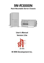
<strong>Mainboard</strong> Layout<br />
Top : mouse<br />
Bottom: keyboard<br />
T:LAN Jack<br />
B:USB Ports<br />
Top : Parallel<br />
Port<br />
Bottom:<br />
COM A<br />
COM B<br />
Top :<br />
Game port<br />
Bottom:<br />
Line-Out<br />
Line-In<br />
Mic<br />
JAUX1<br />
RTL<br />
8101L<br />
JPHN1<br />
MC1<br />
JSP1<br />
Codec<br />
CNR<br />
JIR1<br />
JCI1<br />
JPW1<br />
Winbond<br />
83627HF<br />
JCD1<br />
BIOS<br />
PCI Slot 1<br />
PCI Slot 2<br />
PCI Slot 3<br />
Intel<br />
Brookdale-E<br />
Chipset<br />
AGP Slot<br />
JMDM1<br />
(optional)<br />
<strong>MS</strong>-<strong>6507E</strong> <strong>v1.X</strong> <strong>Micro</strong> <strong>ATX</strong> <strong>Mainboard</strong><br />
1-4<br />
C_FAN1<br />
DDR 1<br />
DDR 2<br />
S_FAN1<br />
ICH4<br />
<strong>ATX</strong><br />
Power Supply<br />
IDE2<br />
JWOL1<br />
(optional)<br />
IDE1<br />
BATT<br />
+<br />
JFP1JFP2<br />
FDD1<br />
JBAT1
Quick Components Guide<br />
1-5<br />
Getting Started<br />
Component Function Reference<br />
Socket 478 Installing CPU See p. 2-2<br />
DDR1~2 Installing DDR modules See p. 2-5<br />
<strong>ATX</strong> Power Connector Installing power supply See p. 2-7<br />
USB Connectors Connecting to USB devices See p. 2-9<br />
COM A & COM B Serial port connector See p. 2-10<br />
LPT1 Parallel port connector See p. 2-11<br />
RJ-45 LAN Jack Connecting to LAN devices See p. 2-12<br />
FDD1 Floppy disk drive connector See p. 2-13<br />
IDE1~ IDE2 Hard disk connectors See p. 2-14<br />
JCD1 CD-in connector See p. 2-15<br />
JAUX1 Aux line-in connector See p. 2-15<br />
JPHN1 Modem-in connector See p. 2-15<br />
C_FAN1/S_FAN1 Fan power connectors See p. 2-16<br />
JCI1 Chassis intrusion switch See p. 2-17<br />
JIR1 IrDA infrared module connector See p. 2-17<br />
JMDM1 Wake On Ring connector See p. 2-18<br />
JWOL1 Wake On LAN connector See p. 2-18<br />
JSP1 SPDIF connector See p. 2-19<br />
JAUD1 Front panel audio connector See p. 2-20<br />
MC1 Modem connector See p. 2-21<br />
JFP1/JFP2 Front panel connector See p. 2-22<br />
JUSB1/JUSB2 Front USB connector See p. 2-23<br />
JBAT1 Clear CMOS jumper See p. 2-24<br />
AGP Slot Connecting to AGP cards See p. 2-25<br />
PCI Slots Connecting to expansion cards See p. 2-25<br />
CNR Slot Connecting to expansion cards See p. 2-25
Chapter 1<br />
Key Features<br />
<strong>Micro</strong> <strong>ATX</strong> Form Factor<br />
PC Alert III system hardware monitor<br />
USB 2.0/1.1 support; a maximum of 6 USB ports<br />
Onboard LAN solution (Realtek RTL8101L)<br />
LAN Wake Up Function<br />
Modem (Internal/External) Ring Wake Up Function<br />
Suspend to RAM/Disk<br />
Support S/PDIF out<br />
<strong>Micro</strong>soft ® PC2001 Compliant<br />
<strong>MS</strong>I proprietary cost effective modem design (Optional)<br />
1-6
<strong>MS</strong>I Special Features<br />
1-7<br />
Getting Started<br />
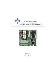
PC Alert III<br />
The PC AlertTM III is a utility you can find in the CD-ROM disk. The<br />
utility is just like your PC doctor that can detect<br />
the following PC hardware status during<br />
real time operation:<br />
* monitor CPU & system temperatures<br />
* monitor fan speed(s)<br />
* monitor system voltage<br />
* monitor chassis intrusion<br />
If one of the items above is abnormal,<br />
the program main screen will be immediately<br />
shown on the screen, with the abnormal item<br />
highlighted in red. This will continue to be<br />
shown until users disable the warning.<br />
Note: Items shown on PC Alert III vary depending on your system’s<br />
status.
Chapter 2. Hardware Setup<br />
Hardware Setup<br />
TOPICS<br />
Central Processing Unit: CPU 2-2<br />
Memory 2-5<br />
Power Supply 2-7<br />
Back Panel 2-8<br />
Connectors 2-13<br />
Jumpers 2-24<br />
Slots 2-25<br />
2-1<br />
Hardware Setup<br />
2<br />
This chapter provides you with the information about hardware setup<br />
procedures. While doing the installation, be careful in holding the components<br />
and follow the installation procedures. For some components, if you install in<br />
the wrong orientation, the components will not work properly.<br />
Use a grounded wrist strap before handling computer components. Static<br />
electricity may damage the components.
Chapter 2<br />
Central Processing Unit: CPU<br />
The mainboard supports Intel ® Pentium ® 4 processor in the 478 pin<br />
package. The mainboard uses a CPU socket called PGA478 for easy CPU<br />
installation. When you are installing the CPU, make sure the CPU has a heat<br />
sink and a cooling fan attached on the top to prevent overheating. If you do not<br />
find the heat sink and cooling fan, contact your dealer to purchase and install<br />
them before turning on the computer.<br />
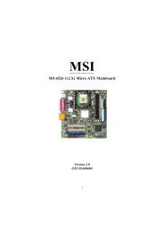
CPU Installation Procedures<br />
1. Pull the lever sideways away<br />
from the socket. Then, raise<br />
the lever up to a 90-degree<br />
angle.<br />
2. Look for the dot/cut edge. The<br />
dot/cut edge should point towards<br />
the lever pivot. The<br />
CPU will only fit in the correct<br />
orientation.<br />
3. Hold the CPU down firmly,<br />
and then close the lever to<br />
complete the installation.<br />
WARNING!<br />
2-2<br />
Sliding<br />
Plate<br />
Dot / Cut edge<br />
Open Lever<br />
Close<br />
Lever<br />
Overheating will seriously damage the CPU and system,<br />
always make sure the cooling fan can work properly to<br />
protect the CPU from overheating.
2-3<br />
Hardware Setup<br />
Installing the CPU Fan<br />
As processor technology pushes to faster speeds and higher<br />
performance, thermal management becomes increasingly important. To dissipate<br />
heat, you need to attach the CPU cooling fan and heatsink on top of the<br />
CPU. Follow the instructions below to install the Heatsink/Fan:<br />
1. Locate the CPU and its retention<br />
mechanism on the motherboard.<br />
retention mechanism<br />
3. Mount the fan on top of the heatsink.<br />
Press down the fan until its four clips<br />
get wedged in the holes of the retention<br />
mechanism.<br />
2. Position the heatsink onto the retention<br />
mechanism.<br />
4. Press the two levers down to fasten<br />
the fan. Each lever can be pressed<br />
down in only ONE direction.<br />
levers
Memory<br />
2-5<br />
Hardware Setup<br />
The mainboard provides 2 slots for 184-pin, 2.5V DDR DIMM with 4<br />
memory banks. You can install DDR200/PC1600 or DDR266/PC2100 DDR<br />
SDRAM modules on the DDR DIMM slots (DDR 1~2). To operate properly, at<br />
least one DIMM module must be installed.<br />
Introduction to DDR SDRAM<br />
DDR (Double Data Rate) SDRAM is similar to conventional SDRAM,<br />
but doubles the rate by transferring data twice per cycle. It uses 2.5 volts as<br />
opposed to 3.3 volts used in SDR SDRAM, and requires 184-pin DIMM modules<br />
rather than 168-pin DIMM modules used by SDR SDRAM. Two types of<br />
DDR are available at the time of writing: PC1600 & PC2100. PC1600 DDR SDRAM<br />
running at 100MHz will produce about 1.6GB/s memory bandwidth. PC2100<br />
running at 133MHz will produce 2.1GB/s memory bandwidth. High memory<br />
bandwidth makes DDR an ideal solution for high performance PC, workstations<br />
and servers.<br />
DDR 1<br />
DDR 2
Chapter 2<br />
DDR Module Combination<br />
You can install either single sided or double sided 184-pin DDR DIMM<br />
modules into DDR DIMM slots to meet your needs. Different from the SDR<br />
DIMM, the DDR DIMM has only one notch on the center of module. The<br />
number of pins on either side of the breaks are different. The module will only<br />
fit in the right orientation.<br />
You can install memory modules in any combination as follows:<br />
Slot Memory Module Total Memory<br />
Slot 1<br />
(Bank 0 & Bank 1)<br />
Slot 2<br />
(Bank 2 & Bank 3)<br />
64MB, 128MB,<br />
256MB, 512MB, 1GB<br />
64MB, 128MB,<br />
256MB, 512MB, 1GB<br />
2-6<br />
64MB~1GB<br />
64MB~1GB<br />
Maximum System Memory Supported 64MB~2GB<br />
Installing DDR Modules<br />
1. The DDR DIMM has only one notch on the center of module. The module<br />
will only fit in the right orientation.<br />
2. Insert the DIMM memory module vertically into the DIMM slot. Then<br />
push it in.<br />
Volt<br />
notch<br />
3. The plastic clip at each side of the DIMM slot will automatically close.
Power Supply<br />
2-7<br />
Hardware Setup<br />
The mainboard supports <strong>ATX</strong> power supply for the power system. Before<br />
inserting the power supply connector, always make sure that all components<br />
are installed properly to ensure that no damage will be caused.<br />
<strong>ATX</strong> 20-Pin Power Connector<br />
This connector allows you to connect to an <strong>ATX</strong> power supply. To<br />
connect to the <strong>ATX</strong> power supply, make sure the plugs of the power supply is<br />
inserted in the proper orientation and the pins are aligned. Then push down<br />
the power supply firmly into the connector. The power connector supports<br />
instant power on function which means that system will boot up immediately<br />
when the power supply connector is inserted on the board.<br />
<strong>ATX</strong> 12V Power Connector: JPW1<br />
This 12V power connector is used to provide power to the CPU.<br />
JPW1<br />
3 4<br />
1 2<br />
JPW1 Pin Definition<br />
PIN SIGNAL<br />
1 GND<br />
2 GND<br />
3 12V<br />
4 12V<br />
PIN SIGNAL<br />
1 3.3V<br />
2 3.3V<br />
3 GND<br />
4 5V<br />
5 GND<br />
6 5V<br />
7 GND<br />
8 PW_OK<br />
9 5V_SB<br />
10 12V<br />
Pin Definition<br />
10<br />
1<br />
PIN SIGNAL<br />
11 3.3V<br />
12 -12V<br />
13 GND<br />
14 PS_ON<br />
15 GND<br />
16 GND<br />
17 GND<br />
18 -5V<br />
19 5V<br />
20 5V<br />
20<br />
11
Chapter 2<br />
Back Panel<br />
The Back Panel provides the following connectors:<br />
Mouse<br />
Keyboard USB<br />
Parallel<br />
COM A COM B L-out L-in MIC<br />
Mouse Connector<br />
The mainboard provides a standard PS/2 ® mouse mini DIN connector for<br />
attaching a PS/2 ® mouse. You can plug a PS/2 ® mouse directly into this<br />
connector. The connector location and pin assignments are as follows:<br />
4<br />
6<br />
LAN<br />
2 1<br />
PS/2 Mouse (6-pin Female)<br />
5<br />
3<br />
2-8<br />
Pin Definition<br />
Midi/Joystick<br />
PIN SIGNAL DESCRIPTION<br />
1 Mouse DATA Mouse DATA<br />
2 NC No connection<br />
3 GND Ground<br />
4 VCC +5V<br />
5 Mouse Clock Mouse clock<br />
6 NC No connection
2-9<br />
Hardware Setup<br />
Keyboard Connector<br />
The mainboard provides a standard PS/2 ® keyboard mini DIN connector<br />
for attaching a PS/2 ® keyboard. You can plug a PS/2 ® keyboard directly into<br />
this connector.<br />
6<br />
4<br />
2 1<br />
PS/2 Keyboard (6-pin Female)<br />
USB Connectors<br />
The mainboard provides a UHCI (Universal Host Controller Interface)<br />
Universal Serial Bus root for attaching USB devices such as keyboard, mouse<br />
or other USB-compatible devices. You can plug the USB device directly into<br />
ths connector.<br />
1 2 3 4<br />
5 6 7 8<br />
USB Ports<br />
5<br />
3<br />
Pin Definition<br />
PIN SIGNAL DESCRIPTION<br />
1 Keyboard DATA Keyboard DATA<br />
2 NC No connection<br />
3 GND Ground<br />
4 VCC +5V<br />
5 Keyboard Clock Keyboard clock<br />
6 NC No connection<br />
USB Port Description<br />
PIN SIGNAL DESCRIPTION<br />
1 VCC +5V<br />
2 -Data 0 Negative Data Channel 0<br />
3 +Data0 Positive Data Channel 0<br />
4 GND Ground<br />
5 VCC +5V<br />
6 -Data 1 Negative Data Channel 1<br />
7 +Data 1 Positive Data Channel 1<br />
8 GND Ground
Chapter 2<br />
Serial Port Connector: COM A & COM B<br />
The mainboard offers two 9-pin male DIN connectors for serial port COM<br />
A and COM B. The ports are 16550A high speed communication ports that<br />
send/receive 16 bytes FIFOs. You can attach a serial mouse or other serial<br />
devices directly to them.<br />
1 2 3 4 5<br />
6 7 8 9<br />
9-Pin Male DIN Connectors<br />
Joystick/Midi Connectors<br />
You can connect a joystick or game pad to this connector.<br />
Audio Port Connectors<br />
Line Out is a connector for Speakers or Headphones. Line In is used for<br />
external CD player, Tape player, or other audio devices. Mic is a connector for<br />
microphones.<br />
1/8” Stereo Audio Connectors<br />
PIN SIGNAL DESCRIPTION<br />
1 DCD Data Carry Detect<br />
2 SIN Serial In or Receive Data<br />
3 SOUT Serial Out or Transmit Data<br />
4 DTR Data Terminal Ready)<br />
5 GND Ground<br />
6 DSR Data Set Ready<br />
7 RTS Request To Send<br />
8 CTS Clear To Send<br />
9 RI Ring Indicate<br />
2-10<br />
Pin Definition<br />
Line Out Line In MIC
2-11<br />
Hardware Setup<br />
Parallel Port Connector<br />
The mainboard provides a 25-pin female centronic connector for LPT. A<br />
parallel port is a standard printer port that supports Enhanced Parallel Port<br />
(EPP) and Extended Capabilities Parallel Port (ECP) mode.<br />
13 1<br />
25<br />
Pin Definition<br />
14<br />
PIN SIGNAL DESCRIPTION<br />
1 STROBE Strobe<br />
2 DATA0 Data0<br />
3 DATA1 Data1<br />
4 DATA2 Data2<br />
5 DATA3 Data3<br />
6 DATA4 Data4<br />
7 DATA5 Data5<br />
8 DATA6 Data6<br />
9 DATA7 Data7<br />
10 ACK# Acknowledge<br />
11 BUSY Busy<br />
12 PE Paper End<br />
13 SELECT Select<br />
14 AUTO FEED# Automatic Feed<br />
15 ERR# Error<br />
16 INIT# Initialize Printer<br />
17 SLIN# Select In<br />
18 GND Ground<br />
19 GND Ground<br />
20 GND Ground<br />
21 GND Ground<br />
22 GND Ground<br />
23 GND Ground<br />
24 GND Ground<br />
25 GND Ground
Chapter 2<br />
LAN Jack (RJ-45)<br />
The mainboard provides one standard RJ-45 jack for connection to Local<br />
Area Network (LAN). You can connect a network cable to the LAN jack.<br />
RJ-45 LAN Jack<br />
2-12<br />
Pin Definition<br />
PIN SIGNAL DESCRIPTION<br />
1 TDP Transmit Differential Pair<br />
2 TDN Transmit Differential Pair<br />
3 RDP Receive Differential Pair<br />
4 NC Not Used<br />
5 NC Not Used<br />
6 RDN Receive Differential Pair<br />
7 NC Not Used<br />
8 NC Not Used
Connectors<br />
2-13<br />
Hardware Setup<br />
The mainboard provides connectors to connect to FDD, IDE HDD, case,<br />
modem, LAN, USB Ports, IR module and CPU/System FAN.<br />
Floppy Disk Drive Connector: FDD1<br />
The mainboard provides a standard floppy disk drive connector that<br />
supports 360K, 720K, 1.2M, 1.44M and 2.88M floppy disk types.<br />
FDD1
Chapter 2<br />
Hard Disk Connectors: IDE1 & IDE2<br />
The mainboard has a 32-bit Enhanced PCI IDE and Ultra DMA 33/66/100<br />
controller that provides PIO mode 0~4, Bus Master, and Ultra DMA33/66/100<br />
function. You can connect up to four hard disk drives, CD-ROM, 120MB Floppy<br />
(reserved for future BIOS) and other devices. These connectors support the<br />
provided IDE hard disk cable.<br />
IDE1 (Primary IDE Connector)<br />
The first hard drive should always be connected to IDE1. IDE1 can<br />
connect a Master and a Slave drive. You must configure second hard<br />
drive to Slave mode by setting the jumper accordingly.<br />
IDE2 (Secondary IDE Connector)<br />
IDE2 can also connect a Master and a Slave drive.<br />
TIP:<br />
If you install two hard disks on cable, you must configure the<br />
second drive to Slave mode by setting its jumper. Refer to the<br />
hard disk documentation supplied by hard disk vendors for jumper<br />
setting instructions.<br />
2-14<br />
IDE 2<br />
IDE 1
CD-In Connector: JCD1<br />
The connector is for CD-ROM audio connector.<br />
2-15<br />
Hardware Setup<br />
Aux Line-In Connector: JAUX1<br />
The connector is for DVD add-on card with Line-in connector.<br />
Modem-In Connector: JPHN1<br />
The connector is for modem with internal audio connector.<br />
R<br />
GND<br />
L<br />
Mono_Out<br />
Phone_In<br />
JAUX1<br />
GND<br />
JPHN1<br />
R<br />
GND<br />
L<br />
JCD1
Chapter 2<br />
Fan Power Connectors: C_FAN1/S_FAN1<br />
The C_FAN1 (processor fan) & S_FAN1 (system fan) support system<br />
cooling fan with +12V. It supports three-pin head connector. When connecting<br />
the wire to the connectors, always take note that the red wire is the positive<br />
and should be connected to the +12V, the black wire is Ground and should be<br />
connected to GND. If the mainboard has a System Hardware Monitor chipset<br />
on-board, you must use a specially designed fan with speed sensor to take<br />
advantage of the CPU fan control.<br />
SENSOR<br />
+12V<br />
GND<br />
Note:<br />
1. Always consult the vendor for proper CPU cooling fan.<br />
2. CPU Fan supports the fan control. You can install the PC Alert<br />
utility that will automatically control the CPU Fan speed according<br />
to the actual CPU temperature.<br />
2-16<br />
C_FAN1<br />
S_FAN1<br />
GND<br />
+12V<br />
SENSOR
2-17<br />
Hardware Setup<br />
Chassis Intrusion Switch Connector: JCI1<br />
This connector is connected to 2-pin connector chassis switch. If the<br />
Chassis is open, the switch will be short. The system will record this status. To<br />
clear the warning, you must enter the BIOS settting and clear the status.<br />
JCI1<br />
IrDA Infrared Module Header: JIR1<br />
This connector allows you to connect to IrDA Infrared modules and is<br />
compliant with Intel ® Front Panel I/O Connectivity Design Guide. You must<br />
configure the setting through the BIOS setup to use the IR function.<br />
JIR1<br />
6 5<br />
2 1<br />
Pin Definition<br />
Pin Signal<br />
1 NC<br />
2 NC<br />
3 VCC<br />
4 GND<br />
5 IRTX<br />
6 IRRX
Chapter 2<br />
Wake On Ring Connector: JMDM1<br />
This connector allows you to connect to a modem card with Wake On<br />
Ring function. The connector will power up the system when a signal is received<br />
through the modem card.<br />
Wake On LAN Connector: JWOL1<br />
This connector allows you to connect to a LAN card with Wake On LAN<br />
function. You can wake up the computer via remote control through a local area<br />
network.<br />
Note: To be able to use this function, you need a power supply that provides<br />
enough power for this feature. (750 mA 5V Stand-by)<br />
2-18<br />
MDM_WAKEUP<br />
NC<br />
5VSB GND NC<br />
JMDM1<br />
1<br />
1<br />
5VSB<br />
GND<br />
JWOL1<br />
MP_WAKEUP
2-19<br />
Hardware Setup<br />
SPDIF Connector: JSP1<br />
The connector is used to connect SPDIF (Sony & Philips Digital Interconnect<br />
Format) interface for digital audio transmission.<br />
1<br />
JSP1<br />
3<br />
Connected to JSP1<br />
JSP1 Pin Definition<br />
PIN SIGNAL<br />
1 VCC<br />
2 SPDIF<br />
3 NC<br />
SPDIF Bracket
Chapter 2<br />
Front Panel Audio Connector: JAUD1<br />
The JAUD1 front panel audio connector allows you to connect to the<br />
front panel audio and is compliant with Intel ® Front Panel I/O Connectivity<br />
Design Guide.<br />
9<br />
10<br />
JAUD1<br />
1<br />
2<br />
Pin Definition<br />
PIN SIGNAL DESCRIPTION<br />
1 AUD_MIC Front panel microphone input signal<br />
2 AUD_GND Ground used by analog audio circuits<br />
3 AUD_MIC_BIAS <strong>Micro</strong>phone power<br />
4 AUD_VCC Filtered +5V used by analog audio circuits<br />
5 AUD_FPOUT_R Right channel audio signal to front panel<br />
6 AUD_RET_R Right channel audio signal return from front panel<br />
7 HP_ON Reserved for future use to control headphone amplifier<br />
8 KEY No pin<br />
9 AUD_FPOUT_L Left channel audio signal to front panel<br />
10 AUD_RET_L Left channel audio signal return from front panel<br />
Note:<br />
If you don’t want to connect to the front audio<br />
header, pins 5 & 6, 9 & 10 have to be jumpered<br />
in order to have signal output directed to the<br />
rear audio ports. Otherwise, the Line-Out connector<br />
on the back panel will not function.<br />
2-20<br />
9<br />
10<br />
5<br />
6
2-21<br />
Hardware Setup<br />
Modem Connector: MC1<br />
This connector is connected to a modem module. The modem module<br />
functions in the same way as a modem, which allows users to connect to the<br />
internet via the telephone line.<br />
2<br />
1<br />
Modem Module<br />
MC1 Pin Definition<br />
PIN SIGNAL DESCRIPTION<br />
1 BIT_CLK (to LAN controller) Serial port bit clock output/input<br />
2 SYNC (from LAN controller) Frame Sync input<br />
3 RESET (from LAN controller) Reset input (active low)<br />
4 SDATA_OUT (from LAN controller) Serial port data input<br />
5 SDATA_IN (to LAN controller) Serial port data output<br />
6 Ground (from M/B) Connect to System Digital Ground<br />
7 Ground (from M/B) Connect to System Digital Ground<br />
8 Aout (to M/B) Analog speaker output<br />
9 +3.3Vaux (from M/B) +3.3V Vaux power input<br />
10 Ground (from M/B) Connect to System Digital Ground<br />
11 +3.3Vaux (from M/B) +3.3V Vaux power input<br />
12 PIN REMOVE PIN REMOVE<br />
MC1<br />
12<br />
11<br />
Connect to a telephone set Connect to a telephone line from the wall
Chapter 2<br />
Front Panel Connectors: JFP1 & JFP2<br />
The mainboard provides two front panel connectors for electrical connection<br />
to the front panel switches and LEDs. JFP1 is compliant with Intel ®<br />
Front Panel I/O Connectivity Design Guide.<br />
JFP1 Pin Definition<br />
JFP2 Pin Definition<br />
2-22<br />
JFP2<br />
PIN SIGNAL PIN SIGNAL<br />
1 GND 2 SPK-<br />
3 SLED 4 BUZ+<br />
5 PLED 6 BUZ-<br />
7 NC 8 SPK+<br />
JFP1<br />
2<br />
1<br />
Power<br />
LED<br />
Power<br />
LED<br />
2<br />
1<br />
Speaker<br />
HDD<br />
LED<br />
PIN SIGNAL DESCRIPTION<br />
1 HD_LED_P Hard disk LED pull-up<br />
2 FP PWR/SLP <strong>MS</strong>G LED pull-up<br />
3 HD_LED_N Hard disk active LED<br />
4 FP PWR/SLP <strong>MS</strong>G LED pull-up<br />
5 RST_SW_N Reset Switch low reference pull-down to GND<br />
6 PWR_SW_P Power Switch high reference pull-up<br />
7 RST_SW_P Reset Switch high reference pull-up<br />
8 PWR_SW_N Power Switch low reference pull-down to GND<br />
9 RSVD_DNU Reserved. Do not use.<br />
8<br />
7<br />
Power<br />
Switch<br />
Reset<br />
Switch<br />
10<br />
9
2-23<br />
Hardware Setup<br />
Front USB Connector: JUSB1 or JUSB2<br />
The mainboard provides two USB 2.0 pin headers JUSB1 & JUSB2<br />
(optional USB 2.0 Bracket available). USB 2.0 technology increases data transfer<br />
rate up to a maximum throughput of 480Mbps, which is 40 times faster than<br />
USB 1.1, and is ideal for connecting high-speed USB interface peripherals such<br />
as USB HDD, digital cameras, MP3 players, printers, modems and the like.<br />
Both JUSB1 & JUSB2 are compliant with Intel ® Front Panel I/O Connectivity<br />
Design Guide.<br />
Pin Definition<br />
9<br />
10<br />
9<br />
10<br />
JUSB2<br />
JUSB1<br />
Pin Description Pin Description<br />
1 VCC 2 VCC<br />
3 USB0- 4 USB1-<br />
5 USB0+ 6 USB1+<br />
7 GND 8 GND<br />
9 NC 10 OC0<br />
1<br />
2<br />
1<br />
2
Chapter 2<br />
Jumpers<br />
The motherboard provides one jumper for you to set the computer’s<br />
function. This section will explain how to change your motherboard’s function<br />
through the use of the jumper.<br />
Clear CMOS Jumper: JBAT1<br />
There is a CMOS RAM on board that has a power supply from external<br />
battery to keep the data of system configuration. With the CMOS RAM, the<br />
system can automatically boot OS every time it is turned on. That battery has<br />
long life time for at least 5 years. If you want to clear the system configuration,<br />
use the JBAT1 (Clear CMOS Jumper ) to clear data. Follow the instructions<br />
below to clear the data:<br />
WARNING!<br />
You can clear CMOS by shorting 2-3 pin while the<br />
system is off. Then return to 1-2 pin position. Avoid<br />
clearing the CMOS while the system is on; it will<br />
damage the mainboard.<br />
2-24<br />
3<br />
1<br />
Keep Data<br />
1<br />
JBAT1<br />
3<br />
1<br />
Clear Data
Slots<br />
2-25<br />
Hardware Setup<br />
The motherboard provides three 32-bit Master PCI bus slots, one AGP<br />
slot and one CNR slot.<br />
AGP Slot<br />
PCI Slots<br />
CNR Slot<br />
AGP (Accelerated Graphics Port) Slot<br />
The AGP slot allows you to insert the AGP graphics card. AGP is an<br />
interface specification designed for the throughput demands of 3D graphics.<br />
It introduces a 66MHz, 32-bit channel for the graphics controller to directly<br />
access main memory. The slot only supports 1.5V 4x AGP card.<br />
PCI Slots<br />
Three PCI slots allow you to insert the expansion cards to meet your<br />
needs. When adding or removing expansion cards, make sure that you unplug<br />
the power supply first. Meanwhile, read the documentation for the expansion<br />
card to make any necessary hardware or software settings for the expansion<br />
card, such as jumpers, switches or BIOS configuration.<br />
CNR (Communication Network Riser)<br />
The CNR slot allows you to insert the CNR expansion cards. CNR is a<br />
specially designed network, audio, or modem riser card for <strong>ATX</strong> family<br />
motherboards. Its main processing is done through software and controlled by<br />
the motherboard’s chipset.
Chapter 2<br />
PCI Interrupt Request Routing<br />
The IRQ, abbreviation of interrupt request line and pronounced I-R-Q,<br />
are hardware lines over which devices can send interrupt signals to the<br />
microprocessor. The PCI IRQ pins are typically connected to the PCI bus INT<br />
A# ~ INT D# pins as follows:<br />
Order 1 Order 2 Order 3 Order 4<br />
PCI Slot 1 INT A# INT B# INT C# INT D#<br />
PCI Slot 2 INT B# INT C# INT D# INT A#<br />
PCI Slot 3 INT C# INT D# INT A# INT B#<br />
2-26
Chapter 3. AWARD ® BIOS Setup<br />
AWARD ® BIOS Setup<br />
3-1<br />
AWARD ® BIOS Setup<br />
TOPICS<br />
Entering Setup 4-2<br />
The Main Menu 4-4<br />
Standard CMOS Features 4-6<br />
Advanced BIOS Features 4-8<br />
Advanced Chipset Features 4-12<br />
Integrated Peripherals 4-14<br />
Power Management Setup 4-18<br />
PNP/PCI Configurations 4-22<br />
PC Health Status 4-24<br />
Frequency/Voltage Control 4-25<br />
Load Fail-Safe/Optimized Defaults 4-27<br />
Set Supervisor/User Password 4-28<br />
3<br />
This chapter provides information on the AWARD ® BIOS Setup program and<br />
allows you to configure the system for optimum use.<br />
You may need to run the Setup program when:<br />
An error message appears on the screen during the system booting up, and<br />
requests you to run SETUP.<br />
You want to change the default settings for customized features.
Chapter 3<br />
Entering Setup<br />
Power on the computer and the system will start POST (Power On Self Test)<br />
process. When the message below appears on the screen, press key to<br />
enter Setup.<br />
Control Keys<br />
Press DEL to enter SETUP<br />
If the message disappears before you respond and you still wish to enter<br />
Setup, restart the system by turning it OFF and On or pressing the RESET<br />
button. You may also restart the system by simultaneously pressing ,<br />
, and keys.<br />
Move to the previous item<br />
Move to the next item<br />
Move to the item in the left hand<br />
Move to the item in the right hand<br />
Select the item<br />
Jumps to the Exit menu or returns to the main menu from a submenu<br />
<strong>Inc</strong>rease the numeric value or make changes<br />
Decrease the numeric value or make changes<br />
General help, only for Status Page Setup Menu and Option Page<br />
Setup Menu<br />
Restore the previous CMOS value from CMOS, only for Option Page<br />
Setup Menu<br />
Load the default CMOS value from Fail-Safe default table, only for<br />
Option Page Setup Menu<br />
Load Optimized defaults<br />
Save all the CMOS changes and exit<br />
3-2
3-3<br />
AWARD ® BIOS Setup<br />
Getting Help<br />
After entering the Setup menu, the first menu you will see is the Main Menu.<br />
Main Menu<br />
The main menu lists the setup functions you can make changes to. You can use<br />
the control keys ( ↑↓ ) to select the item. The on-line description of the highlighted<br />
setup function is displayed at the bottom of the screen.<br />
Sub-Menu<br />
If you find a right pointer symbol (as shown<br />
in the right view) appears to the left of certain<br />
fields that means a sub-menu can be<br />
launched from this field. A sub-menu contains<br />
additional options for a field parameter.<br />
You can use control keys ( ↑↓ ) to highlight<br />
the field and press to call up the<br />
sub-menu. Then you can use the control keys to enter values and move from<br />
field to field within a sub-menu. If you want to return to the main menu, just<br />
press the .<br />
General Help <br />
The BIOS setup program provides a General Help screen. You can call up this<br />
screen from any menu by simply pressing . The Help screen lists the<br />
appropriate keys to use and the possible selections for the highlighted item.<br />
Press to exit the Help screen.
Chapter 3<br />
The Main Menu<br />
Once you enter Award ® BIOS CMOS Setup Utility, the Main Menu (Figure 1)<br />
will appear on the screen. The Main Menu allows you to select from twelve<br />
setup functions and two exit choices. Use arrow keys to select among the items<br />
and press to accept or enter the sub-menu.<br />
Standard CMOS Features<br />
Use this Menu for basic system configurations.<br />
Advanced BIOS Features<br />
Use this menu to set the Advanced Features available on your system.<br />
Advanced Chipset Features<br />
Use this menu to change the values in the chipset registers and optimize your<br />
system’s performance.<br />
Integrated Peripherals<br />
Use this menu to specify your settings for integrated peripherals.<br />
Power Management Setup<br />
Use this menu to specify your settings for power management.<br />
3-4
PnP/PCI Configurations<br />
This entry appears if your system supports PnP/PCI.<br />
PC Health Status<br />
This entry shows your PC health status.<br />
3-5<br />
AWARD ® BIOS Setup<br />
Frequency/Voltage Control<br />
Use this menu to specify your settings for frequency/voltage control.<br />
Load Fail-Safe Defaults<br />
Use this menu to load the BIOS default values for minimal but stable system<br />
performance.<br />
Load Optimized Defaults<br />
Use this menu to load the BIOS default values that are factory settings for<br />
optimal system operations.<br />
Set Supervisor/User Password<br />
Use this menu to set User and Supervisor Passwords.<br />
Save & Exit Setup<br />
Save CMOS value changes to CMOS and exit setup.<br />
Exit Without Saving<br />
Abandon all CMOS value changes and exit setup.
Chapter 3<br />
Standard CMOS Features<br />
The items in Standard CMOS Features Menu are divided into 10 categories.<br />
Each category includes no, one or more than one setup items. Use the arrow<br />
keys to highlight the item and then use the or keys to select<br />
the value you want in each item.<br />
Date<br />
The date format is .<br />
day Day of the week, from Sun to Sat, determined by BIOS. Read-only.<br />
month The month from Jan. through Dec.<br />
date The date from 1 to 31 can be keyed by numeric function keys.<br />
year The year, depends on the year of the BIOS<br />
Time<br />
The time format is .<br />
IDE Primary/Secondary Master/Slave<br />
Press PgUp/ or PgDn/ to select Manual, None, Auto type. Note that the<br />
specifications of your drive must match with the drive table. The hard disk will<br />
not work properly if you enter improper information for this category. If your<br />
hard disk drive type is not matched or listed, you can use Manual to define<br />
your own drive type manually.<br />
If you select Manual, related information is asked to be entered to the follow-<br />
3-6
3-7<br />
AWARD ® BIOS Setup<br />
ing items. Enter the information directly from the keyboard. This information<br />
should be provided in the documentation from your hard disk vendor or the<br />
system manufacturer.<br />
If the controller of HDD interface is SCSI, the selection shall be “None”.<br />
If the controller of HDD interface is CD-ROM, the selection shall be “None”.<br />
Access Mode The settings are CHS, LBA, Large, Auto.<br />
Capacity The formatted size of the storage device.<br />
Cylinder Number of cylinders.<br />
Head Number of heads.<br />
Precomp Write precompensation.<br />
Landing Zone Cylinder location of the landing zone.<br />
Sector Number of sectors.<br />
Drive A/B<br />
This item allows you to set the type of floppy drives installed. Available<br />
options are None, 360K, 5.25 in., 1.2M, 5.25 in., 720K, 3.5 in., 1.44M, 3.5 in.,<br />
2.88M, 3.5 in.<br />
Video<br />
The setting controls the type of video adapter used for the primary monitor of<br />
the system. Available options are EGA/VGA , CGA 40, CGA 80 and Mono.<br />
Halt On<br />
The setting determines whether the system will stop if an error is detected at<br />
boot. Available options are:<br />
All Errors The system stops when any error is detected.<br />
No Errors The system doesn’t stop for any detected error.<br />
All, But Keyboard The system doesn’t stop for a keyboard error.<br />
All, But Diskette The system doesn’t stop for a disk error.<br />
All, But Disk/Key The system doesn’t stop for either a disk or a<br />
keyboard error.
Chapter 3<br />
Advanced BIOS Features<br />
Quick Boot<br />
The setting allows the system to skip certain tests while booting. This will<br />
decrease the time needed to boot the system. Setting options: Enabled,<br />
Disabled.<br />
Anti-Virus Protection<br />
The item is to set the Virus Warning feature for IDE Hard Disk boot sector<br />
protection. If the function is enabled and any attempt to write data into this<br />
area is made, BIOS will display a warning message on screen and beep. Settings:<br />
Disabled and Enabled.<br />
CPU L1 & L2 Cache<br />
Cache memory is additional memory that is much faster than conventional<br />
DRAM (system memory). When the CPU requests data, the system transfers<br />
the requested data from the main DRAM into cache memory, for even faster<br />
access by the CPU. The settings enable/disable the internal cache (also known<br />
as L1 or level 1 cache) and external cache (also known as L2 or level 2 cache).<br />
Setting options: Disabled, Enabled.<br />
CPU L3 Cache<br />
Level 3 cache is the extra cache built into motherboards between the micropro-<br />
3-8
3-9<br />
AWARD ® BIOS Setup<br />
cessor and the main memory. Located away from the CPU, the L3 cache is<br />
slower than the L1 & L2 caches. This setting allows you to turn on or off the L3<br />
cache. Setting options: Enabled, Disabled.<br />
Fast Boot<br />
The setting allows the system to boot within 10 seconds, which is compliant<br />
with PC2001 spec. Fast Boot saves more boot time than Quick Boot by skipping<br />
more check items and not displaying standard summary table on the<br />
screen. With this field enabled, system BIOS will automatically set Quick Boot<br />
to Enabled at the same time. Setting options: Enabled, Disabled.<br />
1st/2nd/3rd Boot Device<br />
The items allow you to set the sequence of boot devices where BIOS attempts<br />
to load the disk operating system. The settings are:<br />
Floppy The system will boot from floppy drive.<br />
LS120 The system will boot from LS-120 drive.<br />
HDD-0 The system will boot from the first HDD.<br />
SCSI The system will boot from the SCSI.<br />
CDROM The system will boot from the CD-ROM.<br />
HDD-1 The system will boot from the second HDD.<br />
HDD-2 The system will boot from the third HDD.<br />
HDD-3 The system will boot from the fourth HDD.<br />
ZIP The system will boot from ATAPI ZIP drive.<br />
USB-FDD The system will boot from the floppy drive at USB ports.<br />
USB-ZIP The system will boot from the ZIP drive at USB ports.<br />
USB-CDROM The system will boot from the CD-ROM at USB ports.<br />
USB-HDD The system will boot from the HDD at USB ports.<br />
LAN The system will boot from the Network drive.<br />
Disabled Disable this sequence.<br />
Boot Other Device<br />
Setting the option to Enabled allows the system to try to boot from other<br />
device if the system fails to boot from the 1st/2nd/3rd boot device.<br />
Swap Floppy<br />
Setting to Enabled will swap floppy drives A: and B:.<br />
Seek Floppy<br />
Setting to Enabled will make BIOS seek floppy drive A: before booting the
Chapter 3<br />
system. Settings: Disabled and Enabled.<br />
Boot Up Num-Lock LED<br />
This item is to set the Num Lock status when the system is powered on.<br />
Setting to On will turn on the Num Lock key when the system is powered on.<br />
Setting to Off will allow end users to use the arrow keys on the numeric keypad.<br />
Settings: On and Off.<br />
Gate A20 Option<br />
This item is to set the Gate A20 status. A20 refers to the first 64KB of extended<br />
memory. When the default value Fast is selected, the Gate A20 is controlled by<br />
Port92 or chipset specific method resulting in faster system performance. When<br />
Normal is selected, A20 is controlled by a keyboard controller or chipset<br />
hardware.<br />
Typematic Rate Setting<br />
This item is used to enable or disable the typematic rate setting including<br />
Typematic Rate & Typematic Delay.<br />
Typematic Rate (Chars/Sec)<br />
After Typematic Rate Setting is enabled, this item allows you to set the rate<br />
(characters/second) at which the keys are accelerated. Settings: 6, 8, 10, 12,<br />
15, 20, 24 and 30.<br />
Typematic Delay (Msec)<br />
This item allows you to select the delay between when the key was first pressed<br />
and when the acceleration begins. Settings: 250, 500, 750 and 1000.<br />
Security Option<br />
This specifies the type of BIOS password protection that is implemented. Settings<br />
are described below:<br />
Option Description<br />
Setup The password prompt appears only when end users try to<br />
run Setup.<br />
System A password prompt appears every time when the computer<br />
is powered on or when end users try to run Setup.<br />
3-10
3-11<br />
AWARD ® BIOS Setup<br />
APIC Function<br />
This field is used to enable or disable the APIC (Advanced Programmable<br />
Interrupt Controller). Due to compliance with PC2001 design guide, the system<br />
is able to run in APIC mode. Enabling APIC mode will expand available IRQ<br />
resources for the system. Settings: Enabled and Disabled.<br />
MPS Table Version<br />
This field allows you to select which MPS (Multi-Processor Specification)<br />
version to be used for the operating system. You need to select the MPS<br />
version supported by your operating system. To find out which version to use,<br />
consult the vendor of your operating system. Settings: 1.4 and 1.1.<br />
Boot OS/2 For DRAM > 64MB<br />
This allows you to run the OS/2 ® operating system with DRAM greater than<br />
64MB. Setting options: Yes, No.
Chapter 3<br />
Advanced Chipset Features<br />
The Advanced Chipset Features Setup option is used to change the values of<br />
the chipset registers. These registers control most of the system options in the<br />
computer.<br />
Note: Change these settings only if you are familiar with the chipset.<br />
Configure DRAM Timing<br />
This setting determines whether DRAM timing is configured by reading the<br />
contents of the SPD (Serial Presence Detect) EPROM on the DRAM module.<br />
Selecting By SPD makes the following settings automatically determined by<br />
BIOS according to the configurations on the SPD. Setting options: By SPD, By<br />
User.<br />
CAS# Latency<br />
The field controls the CAS latency, which determines the timing delay<br />
before SDRAM starts a read command after receiving it. Setting options:<br />
1.5, 2, 2.5. 1.5 increases system performance while 2.5 provides more<br />
stable system performance.<br />
Precharge Delay<br />
This setting controls the number of clock cycles for DRAM to be allowed<br />
to precharge from the active state. Setting options: 7, 6, 5.<br />
RAS# to CAS# Delay<br />
This field lets you insert a timing delay between the CAS and RAS strobe<br />
3-12
3-13<br />
AWARD ® BIOS Setup<br />
signals, used when DRAM is written to, read from, or refreshed. Fast<br />
gives faster performance; and Slow gives more stable performance. This<br />
field applies only when synchronous DRAM is installed in the system.<br />
The settings are: 2 and 3.<br />
RAS# Precharge<br />
This item controls the number of cycles for Row Address Strobe (RAS) to<br />
be allowed to precharge. If insufficient time is allowed for the RAS to<br />
accumulate its charge before DRAM refresh, refresh may be incomplete<br />
and DRAM may fail to retain data. This item applies only when synchronous<br />
DRAM is installed in the system. The settings are: 2 and 3.<br />
DRAM Data Integrity Mode<br />
Select ECC (Error-Checking & Correcting Code) or Non-ECC according to the<br />
type of DRAM installed.<br />
DRAM Frequency<br />
Use this item to configure the clock frequency of the installed SDRAM. Settings<br />
are: Auto, DDR200, DDR266.<br />
Delayed Transaction<br />
The chipset has an embedded 32-bit posted write buffer to support delayed<br />
transactions cycles so that transactions to and from the ISA bus are buffered<br />
and PCI bus can perform other transactions while the ISA transaction is<br />
underway. Select Enabled to support compliance with PCI specification version<br />
2.1. The settings are: Enabled and Disabled.<br />
AGP Aperture Size (MB)<br />
This setting controls just how much system RAM can be allocated to AGP for<br />
video purposes. The aperture is a portion of the PCI memory address range<br />
dedicated to graphics memory address space. Host cycles that hit the aperture<br />
range are forwarded to the AGP without any translation. The option allows the<br />
selection of an aperture size of 4, 8, 16, 32, 64, 128, and 256 (MB).
Chapter 3<br />
Integrated Peripherals<br />
On-Chip Primary/Secondary PCI IDE<br />
The integrated peripheral controller contains an IDE interface with support for<br />
two IDE channels. Choose Enabled to activate each channel separately.<br />
IDE Primary/Secondary Master/Slave PIO<br />
The four items allow you to set a PIO (Programmed Input/Output) mode for<br />
each of the four IDE devices that the onboard IDE interface supports. Modes<br />
0~4 provide increased performance. In Auto mode, BIOS automatically determines<br />
the best mode for each IDE device.<br />
IDE Primary/Secondary Master/Slave UDMA<br />
Ultra DMA implementation is possible only if your IDE device supports it and<br />
your operating environment contains a DMA driver. If both your hard drive<br />
and software support Ultra DMA 33, select Auto to enable BIOS support.<br />
3-14
3-15<br />
AWARD ® BIOS Setup<br />
USB Controller<br />
Select Enabled if your system contains a Universal Serial Bus (USB) controller<br />
and you have USB peripherals. The settings are: Enabled, Disabled.<br />
USB Keyboard/Mouse Support<br />
Set to Enabled if your need to use an USB keyboard/mouse in the operating<br />
system that does not support or have any USB driver installed, such as DOS<br />
and SCO Unix.<br />
Init Display First<br />
This item specifies which VGA card is your primary graphics adapter. Settings:<br />
PCI Slot and AGP.<br />
AC’97 Audio<br />
Auto allows the mainboard to detect whether an audio device is used. If the<br />
device is detected, the onboard AC’97 (Audio Codec’97) controller will be<br />
enabled; if not, it is disabled. Disable the controller if you want to use other<br />
controller cards to connect an audio device. Settings: Auto and Disabled.<br />
AC’97 Modem<br />
Auto allows the mainboard to detect whether a modem is used. If a modem is<br />
used, the onboard MC’97 (Modem Codec’97) controller will be enabled; if not,<br />
it is disabled. Disable the controller if you want to use other controller cards to<br />
connect to a modem. Settings: Auto and Disabled.<br />
Onboard LAN Selection<br />
This setting disables/enables the onboard LAN controller. Setting options:<br />
Disabled, Enabled.<br />
IDE HDD Block Mode<br />
This allows your hard disk controller to use the fast block mode to transfer data<br />
to and from the hard disk drive. Block mode is also called block transfer, multiple<br />
commands or multiple sector read/write. Enabled enables IDE controller to<br />
use block mode; Disabled allows the controller to use standard mode.<br />
Floppy Controller<br />
The item is used to enable or disable the onboard Floppy controller. Select<br />
Enabled when you have installed a floppy disk drive and want to use it.
Chapter 3<br />
Serial Port A/B<br />
The items specify the base I/O port address and IRQ for the onboard Serial Port<br />
A/Serial Port B. Selecting Auto allows BIOS to automatically determine the<br />
correct base I/O port address. Settings: Disabled, 3F8/IRQ4, 2F8/IRQ3, 3E8/<br />
IRQ4, 2E8/IRQ3 and Auto.<br />
Serial Port B Mode<br />
The field allows you to specify the operation mode for serial port “COM<br />
B”. Settings are:<br />
Normal: RS-232C Serial Port<br />
IrDA: IrDA-compliant Serial Infrared Port<br />
ASKIR: Amplitude Shift Keyed Infrared Port<br />
RxD, TxD Active<br />
This setting controls the receiving and transmitting speed of the IR peripheral<br />
in use. Setting options: Hi/Hi, Hi/Lo, Lo/Hi, Lo/Lo.<br />
IR Transmission Delay<br />
This setting determines whether the IR transmission rate will be delayed<br />
while converting to receiving mode. Setting options: Disabled, Enabled.<br />
IR Duplex Mode<br />
This setting controls the operating mode of IR transmission/reception.<br />
Setting options: Full, Half. Under Full Duplex mode, synchronous, bidirectional<br />
transmission/reception is allowed. Under Half Duplex mode,<br />
only asynchronous, bi-directional transmission/reception is allowed.<br />
IR Pin Select<br />
Please consult your IR peripheral documentation to select the correct setting<br />
of the TxD and RxD signals. Setting options: RxD2/TxD2, IR-Rx2Tx2.<br />
Parallel Port<br />
This specifies the I/O port address and IRQ of the onboard parallel port. Settings:<br />
378/IRQ7, 278/IRQ5, 3BC/IRQ7 and Disabled.<br />
Parallel Port Mode<br />
SPP : Standard Parallel Port<br />
EPP : Enhanced Parallel Port<br />
ECP : Extended Capability Port<br />
ECP + EPP: Extended Capability Port + Enhanced Parallel Port<br />
3-16
3-17<br />
AWARD ® BIOS Setup<br />
SPP/EPP/ECP/ECP+EPP<br />
To operate the onboard parallel port as Standard Parallel Port only, choose<br />
“SPP.” To operate the onboard parallel port in the EPP mode simultaneously,<br />
choose “EPP.” By choosing “ECP”, the onboard parallel port will operate<br />
in ECP mode only. Choosing “ECP + EPP” will allow the onboard parallel<br />
port to support both the ECP and EPP modes simultaneously.<br />
EPP Version<br />
The onboard parallel port is EPP Spec. compliant, so after the user chooses<br />
the onboard parallel port with the EPP function, the following message will<br />
be displayed on the screen: “EPP Mode Select.” At this time either EPP 1.<br />
7 spec or EPP 1.9 spec can be chosen.<br />
ECP Mode Use DMA<br />
The ECP mode has to use the DMA channel, so choose the onboard<br />
parallel port with the ECP feature. After selecting it, the following message<br />
will appear: “ECP Mode Use DMA.” At this time, the user can choose<br />
between DMA channel 3 or 1.<br />
Onboard Game Port<br />
This setting disables or assigns an address for the onboard game port.<br />
Onboard Midi Port<br />
This setting disables or assigns an address for the onboard midi port.<br />
Midi IRQ Select<br />
This setting specifies an IRQ for the onboard midi port.
Chapter 3<br />
Power Management Setup<br />
The Power Management Setup allows you to configure you system to most<br />
effectively save energy while operating in a manner consistent with your own<br />
style of computer use.<br />
ACPI Function<br />
This item is to activate the ACPI (Advanced Configuration and Power Management<br />
Interface) Function. If your operating system is ACPI-aware, such as<br />
Windows 98SE/2000/ME, select Enabled. Settings: Enabled and Disabled.<br />
ACPI Standby State<br />
This item specifies the power saving modes for ACPI function. Options are:<br />
S1/POS The S1 sleep mode is a low power state. In this state, no<br />
system context (CPU or chipset) is lost and hardware<br />
maintains all system context.<br />
S3/STR The S3 sleep mode is a power-down state in which power<br />
is supplied only to essential components such as main<br />
memory and wake-capable devices and all system context<br />
is saved to main memory. The information stored in<br />
3-18
3-19<br />
AWARD ® BIOS Setup<br />
memory will be used to restore the PC to the previous<br />
state when an “wake up” event occurs.<br />
Power Management/APM<br />
This item is used to select the degree (or type) of power saving and is related<br />
to these modes: Suspend Mode and HDD Power Down. There are three options<br />
for power management:<br />
Min Saving Minimum Power Management. Suspend Mode = 1 Hour.<br />
Max Saving Maximum Power Management. Suspend Mode = 1 Min.<br />
User Define Allows end users to configure each mode separately.<br />
Suspend Type<br />
This setting allows you to select the type of Suspend mode. Setting options:<br />
Stop Grant (saves the state of the entire system to disk and then powers off<br />
the system), PwrOn Suspend (the CPU and core system remain powered on in<br />
a very low-power mode).<br />
Modem Use IRQ<br />
Name the interrupt request (IRQ) line assigned to the modem (if any) on your<br />
system. Activity of the selected IRQ always awakens the system. Settings are<br />
3, 4, 5, 7, 9, 10, 11 and NA.<br />
Suspend Time Out<br />
If system activity is not detected for the length of time specified in this field, all<br />
devices except CPU will be shut off. Settings are Disabled, 1 Min, 2 Min, 4<br />
Min, 8 Min, 12 Min, 20 Min, 30 Min, 40 Min and 1 Hour.<br />
Power Button Function<br />
This setting determines the function of the power button. When set to Power<br />
Off, the power button works as normal power off button. When set to Suspend,<br />
the computer will enter the suspend/sleep mode if you press the power button.<br />
But if the button is pressed for more than four seconds, the computer is turned<br />
off. Setting options: Power Off, Suspend.<br />
Wake Up On PME, Wake Up On Ring, USB Wakeup From S3<br />
These fields specify whether the system will be awakened from power saving<br />
modes when activity or input signal of the specified hardware peripheral or<br />
component is detected.<br />
Note: To use the function of “Wake Up On Ring”, you need to install a<br />
modem supporting power on function.
Chapter 3<br />
CPU THRM-Throttling<br />
The item allows you to specify the CPU speed (at percentage) to which it will<br />
slow down when the CPU reaches the predetermined overheat temperature.<br />
Settings range from 12.5% to 87.5% at 12.5% increment.<br />
Resume by RTC Alarm<br />
The field is used to enable or disable the feature of booting up the system on<br />
a scheduled time/date.<br />
Date (of Month) Alarm<br />
The field specifies the date for Resume by RTC Alarm. Settings: 0~31.<br />
Time (hh:mm:ss) Alarm<br />
The field specifies the time for Resume by RTC Alarm. Format is <br />
.<br />
POWER ON Function<br />
This setting controls which part on the PS/2 mouse or keyboard can power on<br />
the system. Settings: Password, Hot KEY, Mouse Left, Mouse Right, BUTTON<br />
ONLY and Keyboard 98. Please note that this function will only work under S3<br />
mode.<br />
KB Power ON Password<br />
If POWER ON Function is set to Password, then you can set a password in the<br />
field for the PS/2 keyboard to power on the system. Please note that this<br />
function will only work under S3 mode.<br />
Hot Key Power ON<br />
If POWER ON Function is set to Hot KEY, you can assign a hot key combination<br />
in the field for the PS/2 keyboard to power on the system. Settings: Ctrl-<br />
F1 through Ctrl-F12. Please note that this function will only work under S3<br />
mode.<br />
After AC Power Lost<br />
This setting specifies whether your system will reboot after a power failure or<br />
interrupts occurs. Available settings are:<br />
Power Off Leaves the computer in the power off state.<br />
Power On Reboots the computer.<br />
Last State Restores the system to the status before power failure or<br />
interrupt occurs.<br />
3-20
3-21<br />
AWARD ® BIOS Setup<br />
Reload Global Timer Events: Primary/Secondary Master/Slave IDE, FDC/<br />
LPT/COM Ports<br />
Global Timer Events are I/O events whose occurrence can prevent the system<br />
from entering a power saving mode or can awaken the system from such a<br />
mode. In effect, the system remains alert for anything which occurs to a device<br />
that is configured as Enabled, even when the system is in a power down mode.
Chapter 3<br />
PNP/PCI Configurations<br />
This section describes configuring the PCI bus system. PCI, or Peripheral<br />
Component Interconnect, is a system which allows I/O devices to operate at<br />
speeds nearing the speed the CPU itself uses when communicating with its<br />
own special components. This section covers some very technical items and it<br />
is strongly recommended that only experienced users should make any changes<br />
to the default settings.<br />
Reset Configuration Data<br />
Normally, you leave this field Disabled. Select Enabled to reset Extended System<br />
Configuration Data (ESCD) when you exit Setup if you have installed a<br />
new add-on and the system reconfiguration has caused such a serious conflict<br />
that the operating system can not boot. The settings are: Enabled and Disabled.<br />
Resource Controlled By<br />
The Award Plug and Play BIOS has the capacity to automatically configure all<br />
of the boot and Plug and Play compatible devices. However, this capability<br />
means absolutely nothing unless you are using a Plug and Play operating<br />
system such as Windows ® 95/98. If you set this field to “manual” choose<br />
specific resources by going into each of the sub menu that follows this field (a<br />
sub menu is preceded by a “”). The settings are: Auto (ESCD), Manual.<br />
IRQ Resources<br />
The items are adjustable only when Resources Controlled By is set to Manual.<br />
3-22
3-23<br />
AWARD ® BIOS Setup<br />
Press and you will enter the sub-menu of the items. IRQ Resources list<br />
IRQ 3/4/5/7/9/10/11/12/14/15 for users to set each IRQ a type depending on the<br />
type of device using the IRQ. Settings are:<br />
PCI Device For Plug & Play compatible devices designed for PCI<br />
bus architecture.<br />
Reserved The IRQ will be reserved for further request.<br />
PCI/VGA Palette Snoop<br />
When set to Enabled, multiple VGA devices operating on different buses can<br />
handle data from the CPU on each set of palette registers on every video<br />
device. Bit 5 of the command register in the PCI device configuration space is<br />
the VGA Palette Snoop bit (0 is disabled). For example, if there are two VGA<br />
devices in the computer (one PCI and one ISA) and the:<br />
VGA Palette Snoop<br />
Bit Setting Action<br />
Disabled Data read or written by the CPU is only directed to the PCI<br />
VGA device’s palette registers.<br />
Enabled Data read or written by the CPU is directed to both the PCI<br />
VGA device’s palette registers and the ISA VGA device’s<br />
palette registers, permitting the palette registers of both VGA<br />
devices to be identical.<br />
The setting must be set to Enabled if any ISA bus adapter in the system<br />
requires VGA palette snooping.
Chapter 3<br />
PC Health Status<br />
This section monitors the current hardware status including CPU/system<br />
temperature, CPU/system fan speeds, Vcore etc. Monitor function is available<br />
only if there is hardware monitoring mechanism onboard.<br />
CPU Critical Temperature<br />
If the CPU temperature reaches the upper limit preset in this setting, the warning<br />
mechanism will be activated. This helps you to prevent the CPU overheat<br />
problem.<br />
Current System/CPU Temperature, System/CPU Fan, Vcore, 3.3V, +5V, +12V,<br />
-12V, -5V, VBAT(V), 5VSB(V)<br />
These items display the current status of all of the monitored hardware devices/components<br />
such as CPU voltages, temperatures and all fans’ speeds.<br />
Chassis Intrusion Detect<br />
Set this option to enable, reset, or disable the chassis intrusion detector. During<br />
Enabled, any intrusion on the system chassis will be recorded. The next<br />
time you turn on the system, it will show a warning message. To be able to clear<br />
those warnings, choose Reset. After clearing the message it will go back to<br />
Enabled.<br />
CPU Shutdown Temperature<br />
This option is for setting the shutdown temperature level for the processor.<br />
When the processor reaches the temperature you set, the system will be shut<br />
down.<br />
3-24
Frequency/Voltage Control<br />
3-25<br />
AWARD ® BIOS Setup<br />
This section controls the frequency/voltage of the CPU and certain onboard<br />
hardware to enhance overall system performance.<br />
CPU Ratio Selection<br />
This setting controls the multiplier that is used to determine the internal clock<br />
speed of the processor relative to the external or motherboard clock speed.<br />
Auto Detect DIMM/PCI Clock<br />
This item is used to auto detect the DIMM/PCI slots. When set to Enabled,<br />
the system will remove (turn off) clocks from empty DIMM/PCI slots to minimize<br />
the electromagnetic interference (EMI). Setting options: Enabled, Disabled.<br />
Spread Spectrum<br />
When the motherboard’s clock generator pulses, the extreme values (spikes)<br />
of the pulses creates EMI (Electromagnetic Interference). The Spread Spectrum<br />
function reduces the EMI generated by modulating the pulses so that the<br />
spikes of the pulses are reduced to flatter curves. If you do not have any EMI<br />
problem, leave the setting at Disabled for optimal system stability and<br />
performance. But if you are plagued by EMI, activate the Spread Spectrum for<br />
EMI reduction. Remember to disable Spread Spectrum if you are overclocking<br />
because even a slight jitter can introduce a temporary boost in clockspeed<br />
which may just cause your overclocked processor to lock up.
Chapter 3<br />
CPU Host/PCI Clock<br />
This setting specifies the clock frequencies of the CPU host bus (FSB) and PCI<br />
buses. It provides a method for end users to overclock the processor<br />
accordingly. When set to Default, the BIOS will use the default clock frequencies<br />
for the CPU host bus and PCI buses.<br />
3-26
Load Fail-Safe/Optimized Defaults<br />
3-27<br />
AWARD ® BIOS Setup<br />
The two options on the main menu allow users to restore all of the BIOS<br />
settings to the default Fail-Safe or Optimized values. The Optimized Defaults<br />
are the default values set by the mainboard manufacturer specifically for optimal<br />
performance of the mainboard. The Fail-Safe Defaults are the default values<br />
set by the BIOS vendor for stable system performance.<br />
When you select Load Fail-Safe Defaults, a message as below appears:<br />
Pressing Y loads the BIOS default values for the most stable, minimal system<br />
performance.<br />
When you select Load Optimized Defaults, a message as below appears:<br />
Pressing Y loads the default factory settings for optimal system performance.
Chapter 3<br />
Set Supervisor/User Password<br />
When you select this function, a message as below will appear on the screen:<br />
Type the password, up to six characters in length, and press . The<br />
password typed now will replace any previously set password from CMOS<br />
memory. You will be prompted to confirm the password. Retype the password<br />
and press . You may also press to abort the selection and not<br />
enter a password.<br />
To clear a set password, just press when you are prompted to enter the<br />
password. A message will show up confirming the password will be disabled.<br />
Once the password is disabled, the system will boot and you can enter Setup<br />
without entering any password.<br />
When a password has been set, you will be prompted to enter it every time you<br />
try to enter Setup. This prevents an unauthorized person from changing any<br />
part of your system configuration.<br />
Additionally, when a password is enabled, you can also have Award BIOS to<br />
request a password each time the system is booted. This would prevent unauthorized<br />
use of your computer. The setting to determine when the password<br />
prompt is required is the Security Option of the ADVANCED BIOS FEATURES<br />
menu. If the Security Option is set to System, the password is required both at<br />
boot and at entry to Setup. If set to Setup, password prompt only occurs when<br />
you try to enter Setup.<br />
About Supervisor Password & User Password:<br />
Supervisor password: Can enter and change the settings of<br />
the setup menu.<br />
User password: Can only enter but do not have the right<br />
to change the settings of the setup menu.<br />
3-28
Glossary<br />
Glossary<br />
G-1<br />
Glossary<br />
ACPI (Advanced Configuration & Power Interface)<br />
This power management specification enables the OS (operating system) to control the<br />
amount of power given to each device attached to the computer. Windows 98/98SE,<br />
Windows 2000 and Windows ME can fully support ACPI to allow users managing the<br />
system power flexibly.<br />
AGP (Accelerated Graphics Port)<br />
A new, high-speed graphics interface that based on PCI construction and designed<br />
especially for the throughput demands of 3-D graphics. AGP provides a direct channel<br />
(32-bit wide bus) between the display controller and main memory for high graphics<br />
quality and performance.<br />
<strong>ATX</strong><br />
A modern shape and layout of mainboard that supersedes the widely-used Baby AT<br />
form factor. It improves many placement of components and makes a more efficient<br />
design.<br />
BIOS (basic input/output system)<br />
On PCs, an essential software that contains all the control code of input/output interface<br />
(such as keyboard, disk drives, etc.). It executes hardware test on booting the<br />
system, starts the OS, and provides an interface between the OS and the components.<br />
The BIOS is stored in a ROM chip.<br />
Bus<br />
A set of hardware lines within the computer system, through which the data is transferred<br />
among different components. In a PC, the term bus usually refers to a local bus<br />
that connects the internal components to the CPU and main memory.<br />
Cache<br />
A special memory subsystem that is used to speed up the data transfer. It stores the<br />
contents of frequently accessed RAM locations and the addresses where these data<br />
items are stored.<br />
Chipset<br />
A collection of integrated chips designed to perform one or more related functions. For
Glossary<br />
example, a modem chipset contains all the primary circuits for transmitting and receiving<br />
data; a PC chipset provides the electronic interfaces between all subsystems.<br />
CMOS (complementary metal-oxide semiconductor)<br />
CMOS is a widely used type of semiconductor, which features high speed and low<br />
power consumption. PCs usually contain a small amount of battery-powered CMOS<br />
memory to retain the date, time, and system setup parameters.<br />
COM<br />
In <strong>MS</strong>-DOS system, the name of a serial communications port. DOS supports four<br />
serial ports. For example, if a modem is connected to one serial port and a serial mouse<br />
to another, they are identified as COM1 and COM2.<br />
DIMM (dual in-line memory module)<br />
A small circuit board that holds memory chips. A SIMM (single in-line memory<br />
module) has a 32-bit path to the memory chips whereas a DIMM has 64-bit path.<br />
DRAM (Dynamic RAM)<br />
A most common type of computer memory. It usually uses one transistor and a<br />
capacitor to represent a bit. As the development of technology, the memory type and<br />
specification used in computer becomes variety, such as SDRAM, DDR SDRAM, and<br />
RDRAM. For further instruction, please see the table below:<br />
Dynamic RAM (DRAM) Memory Technologies<br />
Type<br />
First Used Clock Rate Bus* Width Peak<br />
Bandwidth<br />
Volts<br />
FPM (60,70ns)<br />
1990 25MHz 64 bits 200 MBps 5v<br />
EDO (50,60,70ns) 1994 40MHz 64 bits 320 MBps 5v<br />
SDRAM (66MHz) 1996 66MHz 64 bits 528 MBps 3.3v<br />
SDRAM (100MHz) 1998 100MHz 64 bits 800 MBps 3.3v<br />
SDRAM (133MHz) 1999 133MHz 64 bits 1.1 GBps 3.3v<br />
RDRAM (Direct Rambus) 1999 400MHz 16 bits 1.6 GBps 2.5v<br />
DDR SDRAM (100MHz) 2000 100MHz 64 bits 1.6 GBps 3.3v<br />
DDR SDRAM (133MHz) 2000 133MHz 64 bits 2.1 GBps 3.3v<br />
* Memory channel width (64 bits started with 75MHz Pentium)<br />
Source: Computer Desktop Encyclopedia<br />
G-2
G-3<br />
Glossary<br />
ECC Memory (error correcting code memory)<br />
A type of memory that contains special circuitry for testing the accuracy of data and<br />
correcting the errors on the fly.<br />
IDE (Integrated Drive Electronics)<br />
A type of disk-drive interface widely used to connect hard disks, CD-ROMs and tape<br />
drives to a PC, in which the controller electronics is integrated into the drive itself,<br />
eliminating the need for a separate adapter card. The IDE interface is known as the<br />
ATA (AT Attachment) specification.<br />
IEEE 1394<br />
A new, high speed external bus standard, also known as FireWire or iLink, which<br />
supports data transfer rates of up to 400 Mbps for connecting up to 63 external<br />
devices.<br />
IrDA (Infrared Data Association)<br />
A group of device vendors, including computer, component and telecommunications,<br />
who have developed a standard for transmitting data via infrared light waves. This<br />
enables you to transfer data from one device to another without any cables.<br />
LAN (local area network)<br />
A computer network that covers a relatively smaller area, such as in a building or an<br />
enterprise. It is made up of servers, workstations, shared resources, a network operating<br />
system and a communications link. These individual PCs and devices on a LAN<br />
are known as “nodes”, and are connected by cables to access data and devices anywhere<br />
on the LAN, so that many users can share expensive devices and data.<br />
LED (light emitting diode)<br />
A semiconductor device that converts electrical energy into light. Since it lights up<br />
(usually red) when electricity is passed through it, it is usually used for the activity<br />
lights on computer’s component, such as disk drivers.<br />
LPT (line printer terminal)<br />
Logical device name for a line printer; a name reserved by the <strong>MS</strong>-DOS for up to three<br />
parallel printer ports: LPT1, LPT2, and LPT3. It is frequently used by the OS to<br />
identify a printer.
Glossary<br />
PCI (Peripheral Component Interconnect)<br />
A local bus standard developed by Intel that first appeared on PCs in late 1993. PCI<br />
provides “plug and play” capability and allows IRQs to be shared. The PCI controller<br />
can exchange data with the system's CPU either 32 bits or 64 bits at a time.<br />
PnP (Plug and Play)<br />
A set of specifications that allows a PC to configure itself automatically to work with<br />
peripherals. The user can "plug" in a peripheral device and "play" it without configuring<br />
the system manually. To implement this useful feature, both the BIOS that supports<br />
PnP and a PnP expansion card are required.<br />
POST (Power On Self Test)<br />
During booting up your system, the BIOS executes a series of diagnostic tests, include<br />
checking the RAM, the keyboard, the disk drives, etc., to see if they are properly<br />
connected and operating.<br />
PS/2 Port<br />
A type of port developed by IBM for connecting a mouse or keyboard to a PC. The<br />
PS/2 port supports a mini DIN plug containing just 6 pins. Most modern PCs equipped<br />
with PS/2 ports so that the special port can be used by another device, such as a<br />
modem.<br />
USB (universal serial bus)<br />
A hardware interface for low-speed peripherals such as the keyboard, mouse, joystick,<br />
etc. USB provides a maximum bandwidth of 12 Mbit/sec (Mbps) for connecting up to<br />
127 peripheral devices to PC. USB features hot swap capability and multiple data<br />
streams, allows external devices to be plugged in and unplugged without turning the<br />
system off.<br />
Virus<br />
A program or a piece of code that infects computer files by inserting in those files<br />
copies of itself. The virus code is buried within an existing program, and is activated<br />
when that program is executed. All the viruses are man-made, and often have damaging<br />
side effects.<br />
G-4