E7505 Master-LS2 (MS-9121 v1.X) - Premio, Inc.
E7505 Master-LS2 (MS-9121 v1.X) - Premio, Inc.
E7505 Master-LS2 (MS-9121 v1.X) - Premio, Inc.

You also want an ePaper? Increase the reach of your titles
YUMPU automatically turns print PDFs into web optimized ePapers that Google loves.
<strong>E7505</strong> <strong>Master</strong>-<strong>LS2</strong><br />
<strong>MS</strong>-<strong>9121</strong> (<strong>v1.X</strong>) E-ATX Mainboard<br />
Version 1.0<br />
G52-S<strong>9121</strong>X1<br />
i
Manual Rev: 1.0<br />
Release Date: Oct. 2002<br />
FCC-A Radio Frequency Interference Statement<br />
This equipment has been tested and found to comply with the limits for a class<br />
A digital device, pursuant to part 15 of the FCC rules. These limits are designed<br />
to provide reasonable protection against harmful interference when the equipment<br />
is operated in a commercial environment. This equipment generates, uses<br />
and can radiate radio frequency energy and, if not installed and used in accordance<br />
with the instruction manual, may cause harmful interference to radio<br />
communications. Operation of this equipment in a residential area is likely to<br />
cause harmful interference, in which case the user will be required to correct<br />
the interference at his own expense.<br />
Notice 1<br />
The changes or modifications not expressly approved by the party responsible<br />
for compliance could void the user’s authority to operate the equipment.<br />
Notice 2<br />
Shielded interface cables and A.C. power cord, if any, must be used in order to<br />
comply with the emission limits.<br />
VOIR LA NOTICE D’INSTALLATION AVANT DE RACCORDER AU<br />
RESEAU.<br />
Micro-Star International <strong>MS</strong>-<strong>9121</strong><br />
Tested to comply<br />
with FCC Standard<br />
For Home or Office Use<br />
ii
Copyright Notice<br />
The material in this document is the intellectual property of MICRO-STAR<br />
INTERNATIONAL. We take every care in the preparation of this document,<br />
but no guarantee is given as to the correctness of its contents. Our products<br />
are under continual improvement and we reserve the right to make changes<br />
without notice.<br />
Trademarks<br />
All trademarks are the properties of their respective owners.<br />
Intel ® and Pentium ® are registered trademarks of Intel Corporation.<br />
PS/2 and OS ® /2 are registered trademarks of International Business Machines<br />
Corporation.<br />
Windows ® 95/98/2000/NT/XP are registered trademarks of Microsoft<br />
Corporation.<br />
Netware ® is a registered trademark of Novell, <strong>Inc</strong>.<br />
Award ® is a registered trademark of Phoenix Technologies Ltd.<br />
AMI ® is a registered trademark of American Megatrends <strong>Inc</strong>.<br />
Revision History<br />
Revision Revision History Date<br />
V1.0 First release Oct. 2002<br />
Technical Support<br />
If a problem arises with your system and no solution can be obtained from the<br />
user’s manual, please contact your place of purchase or local distributor.<br />
Alternatively, please try the following help resources for further guidance.<br />
Visit the <strong>MS</strong>I website for FAQ, technical guide, BIOS updates, driver<br />
updates, and other information: http://www.msi.com.tw/<br />
Contact our technical staff at: support@msi.com.tw<br />
iii
Safety Instructions<br />
1. Always read the safety instructions carefully.<br />
2. Keep this User’s Manual for future reference.<br />
3. Keep this equipment away from humidity.<br />
4. Lay this equipment on a reliable flat surface before setting it up.<br />
5. The openings on the enclosure are for air convection hence protects the<br />
equipment from overheating. DO NOT COVER THE OPENINGS.<br />
6. Make sure the voltage of the power source and adjust properly 110/220V<br />
before connecting the equipment to the power inlet.<br />
7. Place the power cord such a way that people can not step on it. Do not<br />
place anything over the power cord.<br />
8. Always Unplug the Power Cord before inserting any add-on card or module.<br />
9. All cautions and warnings on the equipment should be noted.<br />
10. Never pour any liquid into the opening that could damage or cause electrical<br />
shock.<br />
11. If any of the following situations arises, get the equipment checked by a<br />
service personnel:<br />
The power cord or plug is damaged.<br />
Liquid has penetrated into the equipment.<br />
The equipment has been exposed to moisture.<br />
The equipment has not work well or you can not get it work according<br />
to User’s Manual.<br />
The equipment has dropped and damaged.<br />
The equipment has obvious sign of breakage.<br />
12. DO NOT LEAVE THIS EQUIPMENT IN AN ENVIRONMENT<br />
UNCONDITIONED, STORAGE TEMPERATURE ABOVE 60 0 C (140 0 F), IT<br />
MAY DAMAGE THE EQUIPMENT.<br />
CAUTION: Danger of explosion if battery is incorrectly replaced.<br />
Replace only with the same or equivalent type recommended by the<br />
manufacturer.<br />
iv
CONTENTS<br />
FCC-A Radio Frequency Interference Statement .......................................... iii<br />
Copyright Notice .......................................................................................... iii<br />
Revision History ........................................................................................... iii<br />
Technical Support ......................................................................................... iii<br />
Safety Instructions .......................................................................................iv<br />
Chapter 1. Getting Started ........................................................................ 1-1<br />
Mainboard Specifications .................................................................... 1-2<br />
Mainboard Layout ............................................................................... 1-5<br />
<strong>MS</strong>I Special Features ........................................................................... 1-6<br />
PC Alert III ................................................................................. 1-6<br />
Live BIOS/Live Driver ............................................................ 1-6<br />
Live Monitor .............................................................................. 1-8<br />
Chapter 2. Hardware Setup ....................................................................... 2-1<br />
Quick Components Guide .................................................................... 2-2<br />
Central Processing Unit: CPU .............................................................. 2-3<br />
CPU Installation Procedures ......................................................... 2-4<br />
CPU Core Speed Derivation Procedure ......................................... 2-5<br />
Memory ................................................................................................ 2-6<br />
Memory Speed/CPU FSB Support Matrix ..................................... 2-6<br />
DIMM Module Combination......................................................... 2-6<br />
Installing DDR Modules ............................................................... 2-7<br />
Power Supply ....................................................................................... 2-8<br />
SSI 24-Pin Power Connector: POWER1 ......................................... 2-8<br />
SSI 8-Pin Power Connector: POWER2 ........................................... 2-8<br />
Back Panel ............................................................................................ 2-9<br />
Mouse Connector ......................................................................... 2-9<br />
Keyboard Connector ................................................................... 2-10<br />
USB Connectors .......................................................................... 2-10<br />
Serial Port Connector: COM A & COM B ................................... 2-11<br />
v
Audio Port Connectors ............................................................... 2-11<br />
Parallel Port Connector: LPT1 ...................................................... 2-12<br />
RJ-45 LAN Jack: Giga-bit LAN .................................................... 2-13<br />
Connectors ......................................................................................... 2-14<br />
Floppy Disk Drive Connector: FDD1........................................... 2-14<br />
Chassis Intrusion Switch Connector: JCI1 .................................. 2-14<br />
Hard Disk Connectors: IDE1/2 .................................................... 2-15<br />
Fan Power Connectors: CPUFAN1/2, SYSFAN1/2/3/4/5 ............. 2-16<br />
Front Panel Connectors: JFP2, JFP3 ............................................ 2-17<br />
SCSI LED Connector: J18 ............................................................ 2-18<br />
Front USB Connector: JUSB3 ...................................................... 2-18<br />
Wake On LAN Connector: JWL1 ................................................ 2-19<br />
CD-In Connector: JCD1 ............................................................... 2-19<br />
Ultra320 SCSI Connectors: SCSI 1/2 ............................................ 2-20<br />
Jumpers .............................................................................................. 2-21<br />
Clear CMOS Jumper: JBAT1 ........................................................ 2-21<br />
System Configure Jumper: J12 ..................................................... 2-22<br />
BIOS Flash Jumper: J14 ............................................................... 2-22<br />
Buzzer Enable/Disable Jumper: J16 .............................................. 2-23<br />
ASR Enable/Disable Jumper: J17 ................................................. 2-24<br />
Slots ................................................................................................... 2-25<br />
AGP (Accelerated Graphics Port) Pro Slot .................................. 2-25<br />
PCI (Peripheral Component Interconnect) Slots .......................... 2-25<br />
Interrupt Request Routing .......................................................... 2-29<br />
Chapter 3. BIOS Setup .............................................................................. 3-1<br />
Entering Setup...................................................................................... 3-2<br />
Control Keys ................................................................................. 3-2<br />
Getting Help .................................................................................. 3-3<br />
The Main Menu ................................................................................... 3-4<br />
vi
Standard CMOS Features .................................................................... 3-6<br />
Advanced BIOS Features .................................................................... 3-8<br />
Advanced Chipset Features............................................................... 3-12<br />
Integrated Peripherals ........................................................................ 3-15<br />
Power Management Setup ................................................................. 3-19<br />
PNP/PCI Configurations ..................................................................... 3-22<br />
PC Health Status ................................................................................ 3-24<br />
Frequency/Voltage Control ................................................................ 3-25<br />
Load Fail-Safe/Optimized Defaults ..................................................... 3-26<br />
Set Supervisor/User Password ........................................................... 3-27<br />
Troubleshooting ........................................................................................ T-1<br />
Glossary ....................................................................................................G-1<br />
vii
Getting Started<br />
Chapter 1. Getting<br />
Started<br />
Getting Started<br />
Thank you for purchasing the <strong>E7505</strong> <strong>Master</strong>-<strong>LS2</strong> (<strong>MS</strong>-<strong>9121</strong><br />
<strong>v1.X</strong>) E-ATX mainboard. The <strong>E7505</strong> <strong>Master</strong>-<strong>LS2</strong> is a superior<br />
computer mainboard based on Intel ® <strong>E7505</strong> & ICH4 chipsets<br />
for optimal system efficiency. Designed to fit the advanced Intel ®<br />
Xeon processor with 512K L2 cache, this mainboard provides<br />
a cost-effective and professional solution for high-end<br />
workstation and server markets.<br />
1-1
<strong>MS</strong>-<strong>9121</strong> E-ATX Mainboard<br />
1-2<br />
Mainboard Specifications<br />
CPU<br />
Supports single/dual Intel ® Xeon processors with 512K L2 cache.<br />
Supports 1.8GHz ~ 2.8GHz and up.<br />
Chipset<br />
Intel ® <strong>E7505</strong> North Bridge<br />
- Supports 100MHz/133MHz system clock.<br />
- Intel ® NetBurst micro-architecture supports 400MHz/533MHz system bus.<br />
- System bus bandwidth of 3.2GB/s & 4.27GB/s.<br />
- Supports DDR266/200 memory.<br />
- Supports AGP 8x/4x.<br />
Intel ® ICH4 South Bridge<br />
- Hi-Speed USB (USB2.0) controller, 480Mb/sec.<br />
- 2 channel Ultra ATA 100 bus <strong>Master</strong> IDE controller.<br />
- PCI <strong>Master</strong> 2.2.<br />
- I/O APIC.<br />
- AC’97 2.2 interface.<br />
- 3 UHCI Host controllers and 1 EHCI Host controller.<br />
Intel ® P64H2 chipset<br />
- Supports 64-bit PCI-X slots at 100MHz..<br />
- Connects directly to the MCH and provides a dedicated path for high<br />
performance I/O.<br />
Main Memory<br />
Supports eight memory banks using four 184-pin DDR DIMMs.<br />
Supports up to 8GB PC2100/PC1600 DDR SDRAMs.<br />
Supports 2.5v DDR SDRAM.<br />
Slots<br />
1 x 8X AGP Pro (50 Watts) slot.<br />
1 x 64bit/100MHz PCI-X slot with support for Zero Channel RAID (PCIX3).<br />
3 x 64bit/100MHz PCI-X slots.<br />
1 x 32bit/33MHz PCI slot.<br />
1 x mini PCI slot.<br />
PCI 2.2, PCI-X, and AGP 3.0 compliant.
Getting Started<br />
Onboard IDE<br />
An IDE controller on the ICH4 chipset provides IDE HDD/CD-ROM with<br />
PIO, Bus <strong>Master</strong> and Ultra DMA100/66/33 operation modes.<br />
Can connect up to four IDE devices.<br />
On-Board Peripherals<br />
On-Board Peripherals include:<br />
- 1 x floppy port supports 2 FDDs with 360K, 720K, 1.2M, 1.44M and<br />
2.88Mbytes<br />
- 2 x serial ports (COM A + COM B)<br />
- 1 x parallel port supports SPP/EPP/ECP mode<br />
- 1 x RJ-45 LAN port<br />
- 2 x SCSI connectors<br />
- 2 x IEEE 1394 ports (Rear x 1/Front x 1) provided by add-in card (Optional)<br />
- 4 x USB 2.0 ports (Rear x 2/Front x 2)<br />
Onboard SCSI<br />
Integrated LSI 53C1030 Ultra320 SCSI controller.<br />
Supports dual channels.<br />
Onboard LAN<br />
Integrated Broadcom ® BCM5703CKHB Gigabit Ethernet controller.<br />
64bit/100MHz PCI-X bus interface.<br />
Onboard Audio<br />
AC’97 audio codec integrated in ICH4 south bridge.<br />
AD 1885 software audio codec.<br />
Vertical audio phonejacks (MIC, Line-In, Line-Out) onboard.<br />
Video Add-In Card (Optional)<br />
ATI Rage XL video controller with 8MB memory.<br />
Mini PCI interface.<br />
IEEE 1394 Add-In Card (Optional)<br />
TI TSB43AB22 1394a Link Layer Controller.<br />
Mini PCI interface.<br />
1-3
<strong>MS</strong>-<strong>9121</strong> E-ATX Mainboard<br />
BIOS<br />
The mainboard BIOS provides “Plug & Play” BIOS which detects the peripheral<br />
devices and expansion cards of the board automatically.<br />
The mainboard provides a Desktop Management Interface (DMI) function<br />
which records your mainboard specifications.<br />
Dimension<br />
Extended ATX Form Factor: 12” x 13”.<br />
Compliant with SSI EEB 3.0.<br />
Mounting<br />
9 mounting holes.<br />
1-4<br />
<strong>MS</strong>I Reminds You...<br />
Enabling the functionality of Hyper-Threading Technology for<br />
your computer system requires ALL of the following platform<br />
Components:<br />
*CPU: Intel ® Pentium ® 4 or Xeon Processors with HT<br />
Technology;<br />
*Chipset: Intel ® Chipsets that support HT Technology;<br />
*BIOS: A BIOS that supports HT Technology and has it enabled;<br />
*OS: An operating system that supports HT Technology.<br />
For more information on Hyper-threading Technology, go to:<br />
http://www.intel.com/info/hyperthreading
Top : mouse<br />
Bottom: keyboard<br />
USB<br />
ports<br />
MEGA TRENDS<br />
PC873661BW<br />
Top :<br />
Parallel Port<br />
Bottom:<br />
COM A<br />
COM B<br />
LAN<br />
Audio<br />
JCD1<br />
J14<br />
J17<br />
Pulse<br />
H5007<br />
Codec<br />
BIOS<br />
SYSFAN1<br />
CPUFAN2<br />
SYSFAN2<br />
BROADCOM<br />
BCM5703CKHB<br />
CPUFAN1<br />
PCI 1<br />
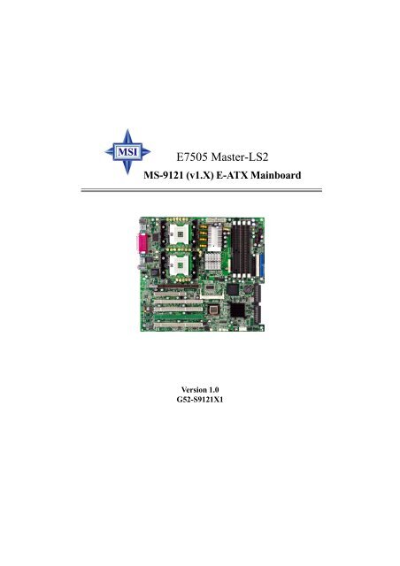
Mainboard Layout<br />
AGP Pro Slot<br />
PCIX1<br />
PCIX2<br />
PCIX3<br />
PCIX4<br />
mPGA604<br />
mPGA604<br />
PCI 2<br />
POWER1<br />
Intel<br />
<strong>E7505</strong><br />
SYSFAN5<br />
P64H2<br />
POWER2<br />
SYSFAN3<br />
Getting Started<br />
<strong>E7505</strong> <strong>Master</strong>-<strong>LS2</strong> (<strong>MS</strong>-<strong>9121</strong> <strong>v1.X</strong>) E-ATX Mainboard<br />
J12<br />
DIMM1<br />
ICH4<br />
DIMM2<br />
SYSFAN4 JWL1 J18<br />
DIMM3<br />
LSI53C1030<br />
J16<br />
JUSB3<br />
DIMM4<br />
JBAT1<br />
BATT<br />
+<br />
FDD 1<br />
IDE 2<br />
JFP2 JFP3<br />
JCI1<br />
SCSI 1<br />
SCSI 2<br />
IDE 1<br />
1-5
<strong>MS</strong>-<strong>9121</strong> E-ATX Mainboard<br />
1-6<br />
<strong>MS</strong>I Special Features<br />
PC Alert III<br />
The PC AlertTM III is a utility you can find in the CD-ROM disk. The<br />
utility is just like your PC doctor that can detect<br />
the following PC hardware status during<br />
real time operation:<br />
monitor CPU & system temperatures<br />
monitor fan speed(s)<br />
monitor system voltage<br />
monitor chassis intrusion<br />
If one of the items above is abnormal,<br />
the program main screen will be immediately<br />
shown on the screen, with the abnormal item<br />
highlighted in red. This will continue to be<br />
shown until user disables the warning.<br />
<strong>MS</strong>I Reminds You...<br />
Items shown on PC Alert III vary depending on your system status.
Live BIOS/Live Driver<br />
The Live BIOS/Live Driver is a tool used to detect and<br />
update your BIOS/drivers online so that you don’t need to search<br />
for the correct BIOS/driver version throughout the Web site. To<br />
use the function, you need to install the “<strong>MS</strong>I Live Update 2”<br />
application. After the installation, the “<strong>MS</strong>I Live Update 2” icon<br />
(as shown on the right) will appear on the screen.<br />
Double click the “<strong>MS</strong>I Live Update 2” icon, and the following<br />
screen will appear:<br />
Getting Started<br />
Five buttons are placed on the leftmost pane of the screen. Click the desired<br />
button to start the update process.<br />
Live BIOS – Updates the BIOS online.<br />
Live Driver – Updates the drivers online.<br />
Live VGA BIOS – Updates the VGA BIOS online.<br />
Live VGA Driver – Updates the VGA driver online.<br />
Live Utility – Updates the utilities online.<br />
If the product you purchased does not support any of the functions listed<br />
above, a “sorry” message is displayed. For more information on the update<br />
instructions, insert the companion CD and refer to the “Live Update Guide”<br />
under the “Manual” Tab.<br />
1-7
<strong>MS</strong>-<strong>9121</strong> E-ATX Mainboard<br />
Live Monitor<br />
The Live Monitor is a tool used to schedule the search<br />
for the latest BIOS/drivers version on the <strong>MS</strong>I Web site. To use<br />
the function, you need to install the “<strong>MS</strong>I Live Update 2”<br />
application. After installation, the “<strong>MS</strong>I Live Monitor” icon (as<br />
shown on the right) will appear on the screen. Double click this<br />
icon to run the application.<br />
Double click the “<strong>MS</strong>I Live Monitor” icon at the lower-right corner<br />
of the taskbar, and the following dialog box will appear. You can specify how<br />
often the system will automatically search for the BIOS/drivers version, or<br />
change the LAN settings right from the dialog box.<br />
You can right-click the <strong>MS</strong>I Live Monitor icon to perform the functions<br />
listed below:<br />
Auto Search – Searches for the BIOS/drivers version you need immediately.<br />
View Last Result – Allows you to view the last search result if there is any.<br />
Preference – Configures the Search function, including the Search schedule.<br />
Exit – Exits the Live Monitor application.<br />
FAQ – Provides a link to a database which contents various possible questions<br />
about <strong>MS</strong>I's products for users to inquire.<br />
1-8
Hardware Setup<br />
Chapter 2. Hardware<br />
Setup<br />
Hardware Setup<br />
This chapter provides you with the information about hardware<br />
setup procedures. While doing the installation, be careful<br />
in holding the components and follow the installation<br />
procedures. For some components, if you install in the wrong<br />
orientation, the components will not work properly.<br />
Use a grounded wrist strap before handling computer<br />
components. Static electricity may damage the components.<br />
2-1
<strong>MS</strong>-<strong>9121</strong> E-ATX Mainboard<br />
Back Panel<br />
I/O, p.2-9<br />
CPUFAN2<br />
SYSFAN2,<br />
p.2-16<br />
JCD1, p.2-19<br />
AGP Pro, p.2-25<br />
J14, p.2-23<br />
PCI Slots, p.2-25<br />
J17, p.2-24<br />
Mini PCI, p.2-26<br />
2-2<br />
CPUFAN1<br />
SYSFAN1, p.2-16<br />
Quick Components Guide<br />
CPU, p.2-3<br />
POWER1, p.2-8<br />
POWER2, p.2-8<br />
SYSFAN3<br />
SYSFAN4<br />
SYSFAN5,<br />
p.2-16<br />
DIMM1~4,<br />
p.2-6<br />
FDD1,<br />
p.2-14<br />
IDE1/2,<br />
p.2-15<br />
JCI1,<br />
p.2-14<br />
JBAT1, p.2-21<br />
J12, p.2-22<br />
SCSI 1<br />
SCSI 2,<br />
p.2-20<br />
JFP3, p.2-17<br />
JFP2, p.2-17<br />
JUSB3, p.2-18<br />
J16, p.2-23<br />
J18, p.2-18<br />
JWL1, p.2-19
Central Processing Unit: CPU<br />
Hardware Setup<br />
The mainboard supports Single/Dual Intel ® Xeon processors and uses<br />
two CPU sockets called Socket 604 for easy CPU installation. You can install<br />
SINGLE or DUAL CPUs on the board to meet your own needs. Keep the<br />
following points in mind before installing CPU(s):<br />
1. If SINGLE CPU is intended, always install the CPU on the CPU1<br />
socket.<br />
CPU1<br />
2. To install DUAL CPUs on the board, you must use the same type<br />
of CPUs running at the same FSB frequency.<br />
When you are installing the CPU, make sure the CPU has a Heat Sink<br />
and a cooling fan attached on the top to prevent overheating. If you do<br />
not find the Heat Sink and cooling fan, contact your dealer to purchase and<br />
install them before turning on the computer.<br />
2-3
<strong>MS</strong>-<strong>9121</strong> E-ATX Mainboard<br />
CPU Installation Procedures<br />
2-4<br />
1. Please turn off the power and<br />
unplug the power cord before<br />
installing the CPU.<br />
2. Pull the lever sideways away<br />
from the socket. Make sure to<br />
raise the lever up to a 90-degree<br />
angle.<br />
3. Look for the gold arrow. The<br />
gold arrow should point towards<br />
the lever pivot. The<br />
CPU can only fit in the correct<br />
orientation.<br />
4. If the CPU is correctly<br />
installed, the pins should be<br />
completely embedded into the<br />
socket and can not be seen.<br />
Please note that any violation<br />
of the correct installation procedures<br />
may cause permanent<br />
damages to your mainboard.<br />
5. Press the CPU down firmly<br />
into the socket and close the<br />
lever. As the CPU is likely to<br />
move while the lever is being<br />
closed, always close the lever<br />
with your fingers pressing<br />
tightly on top of the CPU to<br />
make sure the CPU is properly<br />
and completely embedded<br />
into the socket.<br />
Gold Arrow<br />
Close Lever<br />
Open Lever<br />
Sliding<br />
Plate
CPU Core Speed Derivation Procedure<br />
If CPU Clock = 100MHz<br />
Core/Bus ratio = 14<br />
then CPU core speed = Host Clock x Core/Bus ratio<br />
= 100MHz x 14<br />
= 1.4 GHz<br />
Hardware Setup<br />
<strong>MS</strong>I Reminds You...<br />
Overheating<br />
Overheating will seriously damage the CPU and system, always<br />
make sure the cooling fan can work properly to protect<br />
the CPU from overheating.<br />
Replacing the CPU<br />
While replacing the CPU, always turn off the ATX power supply<br />
or unplug the power supply’s power cord from grounded<br />
outlet first to ensure the safety of CPU.<br />
2-5
<strong>MS</strong>-<strong>9121</strong> E-ATX Mainboard<br />
2-6<br />
Memory<br />
The mainboard provides 4 slots for 184-pin DDR DIMM (Double In-<br />
Line Memory Module) modules and supports the memory size up to 8 GB.<br />
You can install PC2100/DDR266 or PC1600/DDR200 DDR SDRAM modules<br />
on the DDR DIMM slots (DIMM 1~4).<br />
Memory Speed/CPU FSB Support Matrix<br />
DDR200 DDR266<br />
400MHz FSB Yes Yes<br />
533MHz FSB No Yes<br />
DDR DIMM Slots<br />
(DIMM 1~4)<br />
DIMM Module Combination<br />
Install at least two DIMM modules on the slots. Each DIMM slot supports<br />
up to a maximum size of 2GB. You can install either single- or doublesided<br />
modules to meet your own needs, but memory modules must be installed<br />
on the board IN PAIRS.
Hardware Setup<br />
Memory modules can be installed in any combination as follows:<br />
DIMM1 DIMM2 DIMM3 DIMM4 System Density<br />
128MB~2GB 128MB~2GB 256MB~4GB<br />
128MB~2GB 128MB~2GB 256MB~4GB<br />
128MB~2GB 128MB~2GB 128MB~2GB 128MB~2GB 512MB~8GB<br />
<strong>MS</strong>I Reminds You...<br />
Make sure that you install memory modules of the same type and<br />
density on DDR DIMMs “in pairs” -- {DIMM1 & DIMM2}<br />
{DIMM3 & DIMM4}.<br />
Installing DDR Modules<br />
1. The DDR DIMM has only one notch on the center of module. The module<br />
will only fit in the right orientation.<br />
2. Insert the DIMM memory module vertically into the DIMM slot. Then<br />
push it in until the golden finger on the memory module is deeply inserted<br />
in the socket.<br />
<strong>MS</strong>I Reminds You...<br />
You can barely see the golden finger if the module is properly<br />
inserted in the socket.<br />
3. The plastic clip at each side of the DIMM slot will automatically close.<br />
Volt<br />
Notch<br />
2-7
<strong>MS</strong>-<strong>9121</strong> E-ATX Mainboard<br />
2-8<br />
Power Supply<br />
The mainboard supports SSI power supply for the power system. Before<br />
inserting the power supply connector, always make sure that all components<br />
are installed properly to ensure that no damage will be caused.<br />
SSI 24-Pin Power Connector: POWER1<br />
This connector allows you to connect to an SSI power supply. To connect to<br />
the SSI power supply, make sure the plug of the power supply is inserted in<br />
the proper orientation and the pins are aligned. Then push down the power<br />
supply firmly into the connector.<br />
SSI 8-Pin Power Connector: POWER2<br />
This connector provides 12V power output to the CPU.<br />
POWER1 Pin Definition<br />
PIN SIGNAL<br />
1 +3.3V<br />
2 +3.3V<br />
3 GND<br />
4 +5V<br />
5 GND<br />
6 +5V<br />
7 GND<br />
8 PWR OK<br />
9 5VSB<br />
10 +12V<br />
11 +12V<br />
12 +3.3V<br />
PIN SIGNAL<br />
13 +3.3V<br />
14 -12V<br />
15 GND<br />
16 PS-ON#<br />
17 GND<br />
18 GND<br />
19 GND<br />
20 3VSB<br />
21 +5V<br />
22 +5V<br />
23 +5V<br />
24 GND<br />
PIN SIGNAL<br />
1 GND<br />
2 GND<br />
3 GND<br />
4 GND<br />
24 13<br />
12 1<br />
POWER1<br />
8 5<br />
4 1<br />
POWER2<br />
POWER2 Pin Definition<br />
PIN SIGNAL<br />
5 +12V<br />
6 +12V<br />
7 +12V<br />
8 +12V
Back Panel<br />
The back panel provides the following connectors:<br />
Mouse<br />
Keyboard USB<br />
Hardware Setup<br />
Mouse Connector<br />
The mainboard provides a standard PS/2 ® mouse mini DIN connector<br />
for attaching a PS/2 ® mouse. You can plug a PS/2 ® mouse directly into this<br />
connector. The connector location and pin assignments are as follows:<br />
4<br />
6<br />
2 1<br />
PS/2 Mouse (6-pin Female)<br />
5<br />
3<br />
COM A<br />
Parallel<br />
COM B LAN<br />
Pin Definition<br />
PIN SIGNAL DESCRIPTION<br />
1 Mouse DATA Mouse DATA<br />
2 NC No connection<br />
3 GND Ground<br />
4 VCC +5V<br />
5 Mouse Clock Mouse clock<br />
6 NC No connection<br />
MIC<br />
L-In<br />
L-Out<br />
2-9
<strong>MS</strong>-<strong>9121</strong> E-ATX Mainboard<br />
Keyboard Connector<br />
The mainboard provides a standard PS/2 ® keyboard mini DIN connector<br />
for attaching a PS/2 ® keyboard. You can plug a PS/2 ® keyboard directly<br />
into this connector.<br />
2 1<br />
PS/2 Keyboard (6-pin Female)<br />
USB Connectors<br />
The mainboard provides a UHCI (Universal Host Controller Interface)<br />
Universal Serial Bus root for attaching USB devices such as keyboard, mouse<br />
or other USB-compatible devices. You can plug the USB device directly into<br />
the connector.<br />
2-10<br />
4<br />
6<br />
1 2 3 4<br />
5 6 7 8<br />
USB Ports<br />
5<br />
3<br />
Pin Definition<br />
PIN SIGNAL DESCRIPTION<br />
1 Keyboard DATA Keyboard DATA<br />
2 NC No connection<br />
3 GND Ground<br />
4 VCC +5V<br />
5 Keyboard Clock Keyboard clock<br />
6 NC No connection<br />
USB Port Description<br />
PIN SIGNAL DESCRIPTION<br />
1 VCC +5V<br />
2 -Data 0 Negative Data Channel 0<br />
3 +Data0 Positive Data Channel 0<br />
4 GND Ground<br />
5 VCC +5V<br />
6 -Data 1 Negative Data Channel 1<br />
7 +Data 1 Positive Data Channel 1<br />
8 GND Ground
Hardware Setup<br />
Serial Port Connector: COM A & COM B<br />
The mainboard offers two 9-pin male DIN connectors as serial port COM<br />
A and COM B. The ports are 16550A high speed communication ports that<br />
send/receive 16 bytes FIFOs. You can attach a serial mouse or other serial<br />
devices directly to them.<br />
1 2 3 4 5<br />
6 7 8 9<br />
9-Pin Male DIN Connectors<br />
Audio Port Connectors<br />
Line Out is a connector for Speakers or Headphones. Line In is used<br />
for external CD player, Tape player, or other audio devices. Mic is a connector<br />
for microphones.<br />
1/8” Stereo Audio Connectors<br />
Pin Definition<br />
PIN SIGNAL DESCRIPTION<br />
1 DCD Data Carry Detect<br />
2 SIN Serial In or Receive Data<br />
3 SOUT Serial Out or Transmit Data<br />
4 DTR Data Terminal Ready)<br />
5 GND Ground<br />
6 DSR Data Set Ready<br />
7 RTS Request To Send<br />
8 CTS Clear To Send<br />
9 RI Ring Indicate<br />
MIC<br />
Line In<br />
Line Out<br />
2-11
<strong>MS</strong>-<strong>9121</strong> E-ATX Mainboard<br />
Parallel Port Connector: LPT1<br />
The mainboard provides a 25-pin female centronic connector as LPT.<br />
A parallel port is a standard printer port that supports Enhanced Parallel Port<br />
(EPP) and Extended Capabilities Parallel Port (ECP) mode.<br />
2-12<br />
13 1<br />
25<br />
Pin Definition<br />
PIN SIGNAL DESCRIPTION<br />
1 STROBE Strobe<br />
2 DATA0 Data0<br />
3 DATA1 Data1<br />
4 DATA2 Data2<br />
5 DATA3 Data3<br />
6 DATA4 Data4<br />
7 DATA5 Data5<br />
8 DATA6 Data6<br />
9 DATA7 Data7<br />
10 ACK# Acknowledge<br />
11 BUSY Busy<br />
12 PE Paper End<br />
13 SELECT Select<br />
14 AUTO FEED# Automatic Feed<br />
15 ERR# Error<br />
16 INIT# Initialize Printer<br />
17 SLIN# Select In<br />
18 GND Ground<br />
19 GND Ground<br />
20 GND Ground<br />
21 GND Ground<br />
22 GND Ground<br />
23 GND Ground<br />
24 GND Ground<br />
25 GND Ground<br />
14
Hardware Setup<br />
RJ-45 LAN Jack: Giga-bit LAN<br />
The mainboard provides one standard RJ-45 jack for connection to<br />
Local Area Network (LAN). Giga-bit LAN enables data to be transferred at<br />
1000, 100 or 10Mbps. Pin assignments vary depending on the transfer rates:<br />
10/100Mbps or 1000Mbps. Note that Pin 1/2, 3/6, 4/5, 7/8 must work in pairs.<br />
Please refer to the following for details:<br />
Speed Indicator<br />
8 1<br />
RJ-45 LAN Jack<br />
10/100 LAN Pin Definition<br />
PIN SIGNAL DESCRIPTION<br />
1 TDP Transmit Differential Pair<br />
2 TDN Transmit Differential Pair<br />
3 RDP Receive Differential Pair<br />
4 NC Not Used<br />
5 NC Not Used<br />
6 RDN Receive Differential Pair<br />
7 NC Not Used<br />
8 NC Not Used<br />
Giga-bit LAN Pin Definition<br />
Activity Indicator<br />
PIN SIGNAL DESCRIPTION<br />
1 D0P Differential Pair 0+<br />
2 D0N Differential Pair 0-<br />
3 D1P Differential Pair 1+<br />
4 D2P Differential Pair 2+<br />
5 D2N Differential Pair 2-<br />
6 D1N Differential Pair 1-<br />
7 D3P Differential Pair 3+<br />
8 D3N Differential Pair 3-<br />
2-13
<strong>MS</strong>-<strong>9121</strong> E-ATX Mainboard<br />
The mainboard provides connectors to connect to FDD, IDE HDD, case,<br />
modem, LAN, USB Ports, IR module and CPU/System/Power Supply FAN.<br />
Floppy Disk Drive Connector: FDD1<br />
The mainboard provides a standard floppy disk drive connector that<br />
supports 360K, 720K, 1.2M, 1.44M and 2.88M floppy disk types.<br />
2-14<br />
Connectors<br />
FDD1<br />
Chassis Intrusion Switch Connector: JCI1<br />
This connector is connected to a 2-pin chassis switch. If the chassis is<br />
opened, the switch will be short. The system will record this status and show<br />
a warning message on the screen. To clear the warning, you must enter the<br />
BIOS utility and clear the record.<br />
JCI1
Hardware Setup<br />
Hard Disk Connectors: IDE1/2<br />
The mainboard has a 32-bit Enhanced PCI IDE and Ultra DMA 33/66/<br />
100 controller that provides PIO mode 0~4, Bus <strong>Master</strong>, and Ultra DMA 33/<br />
66/100 function. You can connect up to four hard disk drives, CD-ROM,<br />
120MB Floppy (reserved for future BIOS) and other devices. These connectors<br />
support the provided IDE hard disk cable.<br />
IDE2 IDE1<br />
IDE1 (Primary IDE Connector)<br />
The first hard drive should always be connected to IDE1. IDE1 can<br />
connect a <strong>Master</strong> and a Slave drive. You must configure second hard<br />
drive to Slave mode by setting the jumper accordingly.<br />
IDE2 (Secondary IDE Connector)<br />
IDE2 can also connect a <strong>Master</strong> and a Slave drive.<br />
<strong>MS</strong>I Reminds You...<br />
If you install two hard disks on cable, you must configure the<br />
second drive to Slave mode by setting its jumper. Refer to the<br />
hard disk documentation supplied by hard disk vendors for<br />
jumper setting instructions.<br />
2-15
<strong>MS</strong>-<strong>9121</strong> E-ATX Mainboard<br />
Fan Power Connectors: CPUFAN1/2, SYSFAN1/2/3/4/5<br />
The CPUFAN1/2 (processor fans) and SYSFAN1/2/3/4/5 (system fans)<br />
support system cooling fan with +12V. It supports three-pin head connector.<br />
When connecting the wire to the connectors, always take note that the red<br />
wire is the positive and should be connected to the +12V, the black wire is<br />
Ground and should be connected to GND. If the mainboard has a System<br />
Hardware Monitor chipset on-board, you must use a specially designed fan<br />
with speed sensor to take advantage of the CPU fan control.<br />
2-16<br />
SENSOR<br />
+12V<br />
GND<br />
CPUFAN2<br />
SENSOR<br />
+12V<br />
GND<br />
SYSFAN2<br />
SENSOR<br />
+12V<br />
GND<br />
SYSFAN1<br />
SENSOR<br />
+12V<br />
GND<br />
SYSFAN5<br />
SENSOR<br />
+12V<br />
GND<br />
CPUFAN1<br />
SENSOR<br />
+12V<br />
GND<br />
SYSFAN4<br />
SENSOR<br />
+12V<br />
GND<br />
SYSFAN3<br />
<strong>MS</strong>I Reminds You...<br />
Always consult the vendors for proper CPU cooling fan.
Hardware Setup<br />
Front Panel Connectors: JFP2, JFP3<br />
The mainboard provides two front panel connectors for electrical connection<br />
to the front panel switches and LEDs. The JFP2 is compliant with<br />
Intel ® Front Panel I/O Connectivity Design Guide.<br />
JFP3<br />
JFP3 Pin Definition<br />
2<br />
1<br />
PIN SIGNAL PIN SIGNAL<br />
1 GND 2 SPK-<br />
3 SLED 4 BUZ+<br />
5 PLED 6 BUZ-<br />
7 NC 8 SPK+<br />
JFP2 Pin Definition<br />
JFP2<br />
Speaker<br />
Power<br />
LED<br />
8<br />
7<br />
Power<br />
LED<br />
2<br />
1<br />
HDD<br />
LED<br />
PIN SIGNAL DESCRIPTION<br />
1 HD_LED_P Hard disk LED pull-up<br />
2 FP PWR/SLP <strong>MS</strong>G LED pull-up<br />
3 HD_LED_N Hard disk active LED<br />
4 FP PWR/SLP <strong>MS</strong>G LED pull-up<br />
5 RST_SW_N Reset Switch low reference pull-down to GND<br />
6 PWR_SW_P Power Switch high reference pull-up<br />
7 RST_SW_P Reset Switch high reference pull-up<br />
8 PWR_SW_N Power Switch low reference pull-down to GND<br />
9 RSVD_DNU Reserved. Do not use.<br />
Power<br />
Switch<br />
Reset<br />
Switch<br />
10<br />
9<br />
2-17
<strong>MS</strong>-<strong>9121</strong> E-ATX Mainboard<br />
SCSI LED Connector: J18<br />
Connect the J18 to the LED connector on the add-on SCSI adaptor and<br />
the HDD LED will blink when add-on SCSI device is active.<br />
Front USB Connector: JUSB3<br />
The mainboard provides one front Universal Serial Bus connector for<br />
users to connect optional USB ports.<br />
2-18<br />
Pin Definition<br />
PIN SIGNAL<br />
1 VCC5<br />
2 SCSI LED<br />
3 HDD LED<br />
4 VCC5<br />
J18<br />
1 4<br />
Pin Definition<br />
Pin Description Pin Description<br />
1 +5V 6 USBP3+<br />
2 +5V 7 GND<br />
3 USBP2- 8 GND<br />
4 USBP3- 9 NC<br />
5 USBP2+ 10 Key Removed<br />
2<br />
1<br />
JUSB3<br />
10<br />
9
CD-In Connector: JCD1<br />
The connector is for CD-ROM audio connector.<br />
JCD1<br />
L<br />
GND R<br />
Hardware Setup<br />
Wake On LAN Connector: JWL1<br />
This connector allows you to connect to a LAN card with Wake On<br />
LAN function. You can wake up the computer via remote control through a<br />
local area network.<br />
GND<br />
5VSB MP_WAKEUP<br />
1<br />
JWL1<br />
<strong>MS</strong>I Reminds You...<br />
To be able to use this function, you need a power supply that<br />
provides enough power for this feature. (750 mA 5V Stand-by)<br />
2-19
<strong>MS</strong>-<strong>9121</strong> E-ATX Mainboard<br />
Ultra320 SCSI Connectors: SCSI 1/2<br />
SCSI (Small Computer System Interface) is a hardware interface that<br />
allows for connection of up to 15 peripheral devices. The mainboard provides<br />
onboard dual SCSI channels (SCSI 1 & SCSI 2) for you to connect<br />
SCSI devices such as SCSI hard disks.<br />
2-20<br />
SCSI 1<br />
SCSI 2<br />
34<br />
68<br />
68-Pin Ultra320 SCSI Connector<br />
1<br />
26<br />
Pin Description Pin Description<br />
1 +DB(12) 35 -DB(12)<br />
2 +DB(13) 36 -DB(13)<br />
3 +DB(14) 37 -DB(14)<br />
4 +DB(15) 38 -DB(15)<br />
5 +DB(P1) 39 -DB(P1)<br />
6 +DB(0) 40 -DB(0)<br />
7 +DB(1) 41 -DB(1)<br />
8 +DB(2) 42 -DB(2)<br />
9 +DB(3) 43 -DB(3)<br />
10 +DB(4) 44 -DB(4)<br />
11 +DB(5) 45 -DB(5)<br />
12 +DB(6) 46 -DB(6)<br />
13 +DB(7) 47 -DB(7)<br />
14 +DB(P) 48 -DB(P)<br />
15 GROUND 49 GROUND<br />
16 DIFFSENS 50 GROUND<br />
17 TERMPWR 51 TERMPWR<br />
18 TERMPWR 52 TERMPWR<br />
19 RESERVED 53 RESERVED<br />
20 GROUND 54 GROUND<br />
21 +ATN 55 -ATN<br />
22 GROUND 56 GROUND<br />
23 +BSY 57 -BSY<br />
24 +ACK 58 -ACK<br />
25 +RST 59 -RST<br />
26 +<strong>MS</strong>G 60 -<strong>MS</strong>T<br />
27 +SEL 61 -SEL<br />
28 +C/D 62 -C/D<br />
29 +REQ 63 -REQ<br />
30 +I/O 64 -I/O<br />
31 +DB(8) 65 -DB(8)<br />
32 +DB(9) 66 -DB(9)<br />
33 +DB(10) 67 -DB(10)<br />
34 +DB(11) 68 -DB(11)
Jumpers<br />
Hardware Setup<br />
The motherboard provides the following jumpers for you to set the<br />
computer’s function. This section will explain how to change your<br />
motherboard’s function through the use of jumpers.<br />
Clear CMOS Jumper: JBAT1<br />
There is a CMOS RAM on board that has a power supply from external<br />
battery to keep the data of system configuration. With the CMOS RAM, the<br />
system can automatically boot OS every time it is turned on. If you want to<br />
clear the system configuration, use the JBAT1 (Clear CMOS Jumper ) to clear<br />
data. Follow the instructions below to clear the data:<br />
1 3<br />
Keep Data<br />
JBAT1<br />
1<br />
1 3<br />
Clear Data<br />
<strong>MS</strong>I Reminds You...<br />
You can clear CMOS by shorting 2-3 pin while the system is off.<br />
Then return to 1-2 pin position. Avoid clearing the CMOS while<br />
the system is on; it will damage the mainboard.<br />
2-21
<strong>MS</strong>-<strong>9121</strong> E-ATX Mainboard<br />
System Configure Jumper: J12<br />
The J12 jumper determines which mode the system will enter while<br />
powered on. During Normal Mode, the system will enter the assigned OS as<br />
usual. During Configure Mode, the system will directly enter BIOS setup<br />
utility. This enables you to modify the BIOS configurations. During Recovery<br />
Mode, you have to insert certain boot disk into the floppy drive before powering<br />
on the system. After powered on, the system will read the boot disk and<br />
enter DOS. This enables you to update the BIOS with a Flash utility if necessary.<br />
2-22<br />
1 3 1 3<br />
1 3<br />
Normal Mode Configure Mode Recovery Mode<br />
1<br />
J12
Hardware Setup<br />
BIOS Flash Jumper: J14<br />
This jumper is used to protect the BIOS boot block from virus infection.<br />
When locked, the BIOS boot block cannot be accessed, making BIOS update<br />
impossible. When BIOS update is intended, short pin 2 & 3 to disable BIOS<br />
flash protection.<br />
J14<br />
1 3 1 3<br />
BIOS flash locked<br />
1<br />
BIOS flash unlocked<br />
Buzzer Enable/Disable Jumper: J16<br />
This jumper is used to enable/disable the onboard buzzer.<br />
1 3 1 3<br />
Disable Buzzer<br />
1<br />
J16<br />
Enable Buzzer<br />
2-23
<strong>MS</strong>-<strong>9121</strong> E-ATX Mainboard<br />
ASR Enable/Disable Jumper: J17<br />
This jumper is used to enable/disable the ASR (Auto Server Reboot)<br />
function.<br />
2-24<br />
J17<br />
Disable ASR<br />
Enable ASR
Slots<br />
Hardware Setup<br />
The motherboard provides one AGP Pro slot, one 32-bit <strong>Master</strong> PCI<br />
slot, one Mini PCI slot, and four 64-bit PCI-X slots.<br />
AGP Pro Slot<br />
32-bit PCI Slot<br />
64-bit PCI-X Slots<br />
Mini PCI Slot<br />
AGP (Accelerated Graphics Port) Pro Slot<br />
The AGP Pro slot allows you to insert the AGP/AGP Pro graphics card.<br />
AGP is an interface specification designed for the throughput demands of 3D<br />
graphics. It introduces a 66MHz, 32-bit channel for the graphics controller to<br />
directly access main memory.<br />
PCI (Peripheral Component Interconnect) Slots<br />
The PCI slots allow you to insert the expansion cards to meet your needs.<br />
When adding or removing expansion cards, make sure that you unplug the<br />
power supply first. Meanwhile, read the documentation for the expansion card<br />
to make any necessary hardware or software settings for the expansion card,<br />
such as jumpers, switches or BIOS configuration. One PCI slot is conventional<br />
32-bit PCI bus slot and the other four are 64-bit PCI bus (also called<br />
PCI-X) slots.<br />
32-bit PCI bus: The bus has 32 data lines and runs at 33MHz.<br />
64-bit PCI-X bus: The bus has 64 data lines and runs at 100MHz.<br />
With twice data lines and much faster PCI clock, the 64-bit PCI bus<br />
increases the throughput and overall system performance. The 64-bit<br />
PCI-X Slot 3 in GREEN color is the only PCI slot where the Zero<br />
Channel RAID (ZCR) card can be installed.<br />
2-25
<strong>MS</strong>-<strong>9121</strong> E-ATX Mainboard<br />
2-26<br />
Mini PCI bus: This bus is used to connect the <strong>MS</strong>-9513 VGA card or<br />
<strong>MS</strong>-9514 IEEE 1394 card.<br />
Installing the card:<br />
<strong>MS</strong>-9513 VGA card <strong>MS</strong>-9514 IEEE 1394 card<br />
1. Locate the Mini PCI slot on the<br />
mainboard.<br />
2. Place the card over the Mini PCI slot<br />
and gently insert both ends of the card<br />
slantways (at an angle of 45 degrees)<br />
into the slot until the golden finger of<br />
the card gets fully inserted into the slot.<br />
Mini PCI slot<br />
<strong>MS</strong>I Reminds You...<br />
You can barely see the golden finger if the card is properly<br />
inserted in the socket.
3. Locate the supporters on the<br />
mainboard (one on the right end and<br />
the other on the left end). Align the two<br />
fixing holes on the card with the supporters<br />
and press the card carefully<br />
down until the fixing holes get locked<br />
by the supporters.<br />
4. Push the retaining clips (on two ends<br />
of the slot) inwards until they lock onto<br />
the notches in the ends of the card. The<br />
card should securely fit into the slot.<br />
Removing the card:<br />
1. Gently push the retaining clips<br />
outwards. Hold the card lightly but<br />
firmly. Use long nose pliers to clip one<br />
of the supporters and press it downwards<br />
until it withdraws from the fixing<br />
hole.<br />
Hardware Setup<br />
supporters<br />
supporter<br />
2-27
<strong>MS</strong>-<strong>9121</strong> E-ATX Mainboard<br />
2. Clip the other supporter and press it<br />
downwards until it withdraws from the<br />
fixing hole.<br />
3. The card will automatically bound<br />
upwards after being released from the<br />
supporters.<br />
4. Remove the card from the Mini PCI<br />
slot.<br />
2-28<br />
supporter
Hardware Setup<br />
Interrupt Request Routing<br />
The IRQ, acronym of interrupt request line and pronounced I-R-Q, are<br />
hardware lines over which devices can send interrupt signals to the<br />
microprocessor.<br />
DEVICE INT A# INT B# INT C# INT D#<br />
AGP PIRQA_L PIRQB_L N/A N/A<br />
PCI Slot 1 PIRQF_L PIRQG_L PIRQH_L PIRQE_L<br />
PCI Slot 2 (Mini PCI) PIRQG_L N/A N/A N/A<br />
P64H2 PIRQC_L N/A N/A N/A<br />
LSI53C1030 PAIRQ8 PAIRQ9 N/A N/A<br />
PCI-X Slot 3 (SCSI RAID) PAIRQ0 PAIRQ1 N/A N/A<br />
PCI-X Slot 4 PAIRQ4 PAIRQ5 PAIRQ6 PAIRQ7<br />
GIGABIT LAN PBIRQ0 N/A N/A N/A<br />
PCI-X Slot 1 PBIRQ4 PBIRQ5 PBIRQ6 PBIRQ7<br />
PCI-X Slot 2 PBIRQ8 PBIRQ9 PBIRQ10 PBIRQ11<br />
<strong>MS</strong>-9513 (VGA Card) PIRQG_L N/A N/A N/A<br />
<strong>MS</strong>-9514 (1394 Card) PIRQG_L N/A N/A N/A<br />
2-29
BIOS Setup<br />
Chapter 3. BIOS Setup<br />
BIOS Setup<br />
This chapter provides information on the BIOS Setup program<br />
and allows you to configure the system for optimum use.<br />
You may need to run the Setup program when:<br />
An error message appears on the screen during the system<br />
booting up, and requests you to run SETUP.<br />
You want to change the default settings for customized<br />
features.<br />
3-1
<strong>MS</strong>-<strong>9121</strong> E-ATX Mainboard<br />
Control Keys<br />
3-2<br />
Entering Setup<br />
Power on the computer and the system will start POST (Power On Self<br />
Test) process. When the message below appears on the screen, press <br />
key to enter Setup.<br />
Press DEL to enter SETUP<br />
If the message disappears before you respond and you still wish to enter<br />
Setup, restart the system by turning it OFF and On or pressing the RESET<br />
button. You may also restart the system by simultaneously pressing ,<br />
, and keys.<br />
Move to the previous item<br />
Move to the next item<br />
Move to the item in the left hand<br />
Move to the item in the right hand<br />
Select the item<br />
Jumps to the Exit menu or returns to the main menu from a submenu<br />
<strong>Inc</strong>rease the numeric value or make changes<br />
Decrease the numeric value or make changes<br />
General help, only for Status Page Setup Menu and Option Page<br />
Setup Menu<br />
Restore the previous CMOS value from CMOS, only for Option Page<br />
Setup Menu<br />
Load the default CMOS value from Fail-Safe default table, only for<br />
Option Page Setup Menu<br />
Load Optimized defaults<br />
Save all the CMOS changes and exit
BIOS Setup<br />
Getting Help<br />
After entering the Setup menu, the first menu you will see is the Main<br />
Menu.<br />
Main Menu<br />
The main menu lists the setup functions you can make changes to. You<br />
can use the arrow keys ( ↑↓ ) to select the item. The on-line description of the<br />
highlighted setup function is displayed at the bottom of the screen.<br />
Sub-Menu<br />
If you find a right pointer symbol (as shown in the right view) appears<br />
to the left of certain fields that means a submenu<br />
can be launched from this field. A<br />
sub-menu contains additional options for a<br />
field parameter. You can use arrow keys (<br />
↑↓ ) to highlight the field and press <br />
to call up the sub-menu. Then you can use<br />
the control keys to enter values and move from field to field within a submenu.<br />
If you want to return to the main menu, just press the .<br />
General Help <br />
The BIOS setup program provides a General Help screen. You can call<br />
up this screen from any menu by simply pressing . The Help screen lists<br />
the appropriate keys to use and the possible selections for the highlighted<br />
item. Press to exit the Help screen.<br />
<strong>MS</strong>I Reminds You...<br />
The items under each BIOS category described in this chapter<br />
are under continuous update for better system performance.<br />
Therefore, the description may be slightly different from the latest<br />
BIOS and should be held for reference only.<br />
3-3
<strong>MS</strong>-<strong>9121</strong> E-ATX Mainboard<br />
3-4<br />
The Main Menu<br />
Once you enter Award Workstation BIOS CMOS Setup Utility, the Main<br />
Menu will appear on the screen. The Main Menu displays twelve configurable<br />
functions and two exit choices. Use arrow keys to move among the items and<br />
press to enter the sub-menu.<br />
Standard CMOS Features<br />
Use this menu for basic system configurations, such as time, date etc.<br />
Advanced BIOS Features<br />
Use this menu to configure the special enhanced features.<br />
Advanced Chipset Features<br />
Use this menu to change the values in the chipset registers and optimize your<br />
system’s performance.<br />
Integrated Peripherals<br />
Use this menu to specify your settings for integrated peripherals.<br />
Power Management Setup<br />
Use this menu to specify your settings for power management.
PNP/PCI Configurations<br />
This entry appears if your system supports PnP/PCI.<br />
PC Health Status<br />
This entry shows your PC health status.<br />
Frequency/Voltage Control<br />
Use this menu to specify your settings for frequency/voltage control.<br />
BIOS Setup<br />
Load Fail-Safe Defaults<br />
Use this menu to load the BIOS default values for minimal but stable system<br />
performance.<br />
Load Optimized Defaults<br />
Use this menu to load the BIOS default values that are factory settings for<br />
optimal system operations.<br />
Set Supervisor/User Password<br />
Use this menu to set user and supervisor passwords.<br />
Save & Exit Setup<br />
Save changes to CMOS and exit setup.<br />
Exit Without Saving<br />
Abandon all changes and exit setup.<br />
3-5
<strong>MS</strong>-<strong>9121</strong> E-ATX Mainboard<br />
3-6<br />
Standard CMOS Features<br />
The items inside Standard CMOS Features menu are divided into 10<br />
categories. Each category includes none, one or more setup items. Use the<br />
arrow keys to highlight the item you want to modify and use the or<br />
keys to switch to the value you prefer.<br />
Date (mm:dd:yy)<br />
This allows you to set the system to the date that you want (usually the current<br />
date). The format is .<br />
day Day of the week, from Sun to Sat, determined by<br />
BIOS. Read-only.<br />
month The month from Jan. through Dec.<br />
date The date from 1 to 31 can be keyed by numeric<br />
function keys.<br />
year The year can be adjusted by users.<br />
Time (hh:mm:ss)<br />
This allows you to set the system time that you want (usually the current<br />
time). The time format is .<br />
IDE Primary/Secondary <strong>Master</strong>/Slave<br />
Press PgUp/ or PgDn/ to select Manual, None, Auto type. Note that<br />
the specifications of your drive must match with the drive table. The hard disk
BIOS Setup<br />
will not work properly if you enter improper information for this category. If<br />
your hard disk drive type is not matched or listed, you can use Manual to<br />
define your own drive type manually.<br />
If you select Manual, related information is asked to be entered to the following<br />
items. Enter the information directly from the keyboard. This information<br />
should be provided in the documentation from your hard disk vendor or the<br />
system manufacturer.<br />
If the controller of HDD interface is SCSI, the selection shall be “None”. If<br />
the controller of HDD interface is CD-ROM, the selection shall be “None”.<br />
Access Mode The settings are CHS, LBA, Large, Auto.<br />
Capacity The formatted size of the storage device.<br />
Cylinder Number of cylinders.<br />
Head Number of heads.<br />
Precomp Write precompensation.<br />
Landing Zone Cylinder location of the landing zone.<br />
Sector Number of sectors.<br />
Drive A/B<br />
This item allows you to set the type of floppy drives installed. Available<br />
options are None, 360K, 5.25 in., 1.2M, 5.25 in., 720K, 3.5 in., 1.44M, 3.5 in.,<br />
2.88M, 3.5 in.<br />
Video<br />
The setting controls the type of video adapter used for the primary monitor of<br />
the system. Available options are EGA/VGA , CGA 40, CGA 80 and Mono.<br />
Halt On<br />
The setting determines whether the system will stop if an error is detected at<br />
boot. Available options are:<br />
All Errors The system stops when any error is detected.<br />
No Errors The system doesn’t stop for any detected error.<br />
All, But Keyboard The system doesn’t stop for a keyboard error.<br />
All, But Diskette The system doesn’t stop for a disk error.<br />
All, But Disk/Key The system doesn’t stop for either a disk or a keyboard<br />
error.<br />
3-7
<strong>MS</strong>-<strong>9121</strong> E-ATX Mainboard<br />
3-8<br />
Advanced BIOS Features<br />
Virus Warning<br />
The item is to set the Virus Warning feature for IDE Hard Disk boot sector<br />
protection. If the function is enabled and any attempt to write data into this<br />
area is made, BIOS will display a warning message on screen and beep. Setting<br />
options: Disabled, Enabled.<br />
CPU L1 & L2 Cache<br />
Cache memory is additional memory that is much faster than conventional<br />
DRAM (system memory). When the CPU requests data, the system transfers<br />
the requested data from the main DRAM into cache memory, for even faster<br />
access by the CPU. The settings enable/disable the internal cache (also known<br />
as L1 or level 1 cache) and external cache (also known as L2 or level 2 cache).<br />
Setting options: Disabled, Enabled.<br />
CPU L3 Cache<br />
Level 3 cache is the extra cache built into motherboards between the microprocessor<br />
and the main memory. Located away from the CPU, the L3 cache is<br />
slower than the L1 & L2 caches. This setting allows you to turn on or off the<br />
L3 cache. Setting options: Enabled, Disabled.<br />
CPU Hyper-Threading<br />
With Intel ® Hyper-Threading Technology, a single Hyper-Threading-enabled
BIOS Setup<br />
processor can simultaneously process two threads of code, improving the performance<br />
of multi-threaded code running on a single processor platform. Setting<br />
this function to Enabled will improve overall system performance, increase<br />
number of users a platform can support, improve reaction and response<br />
time, and increase number of transaction that can be executed. Setting options:<br />
Enabled, Disabled.<br />
<strong>MS</strong>I Reminds You...<br />
Enabling the functionality of Hyper-Threading Technology for your<br />
computer system requires ALL of the following platform<br />
Components:<br />
*CPU: Intel ® Pentium ® 4 or Xeon Processors with HT<br />
Technology;<br />
*Chipset: Intel ® Chipsets that support HT Technology;<br />
*BIOS: A BIOS that supports HT Technology and has it enabled;<br />
*OS: An operating system that supports HT Technology.<br />
For more information on Hyper-threading Technology, go to:<br />
http://www.intel.com/info/hyperthreading<br />
First/Second/Third Boot Device<br />
The items allow you to set the sequence of boot devices where BIOS attempts<br />
to load the disk operating system. The settings are:<br />
Floppy The system will boot from floppy drive.<br />
LS120 The system will boot from LS-120 drive.<br />
HDD-0 The system will boot from the first HDD.<br />
SCSI The system will boot from the SCSI device.<br />
CDROM The system will boot from the CD-ROM.<br />
HDD-1 The system will boot from the second HDD if available.<br />
HDD-2 The system will boot from the third HDD if available.<br />
HDD-3 The system will boot from the fourth HDD if available.<br />
ZIP100 The system will boot from ATAPI ZIP drive.<br />
LAN The system will boot from the network drive.<br />
Disabled Disable this sequence.<br />
<strong>MS</strong>I Reminds You...<br />
Available settings for “First/Second/Third Boot Device” vary<br />
depending on the bootable devices you have installed. For<br />
example, if you did not install a floppy drive, the setting “Floppy”<br />
does not show up.<br />
3-9
<strong>MS</strong>-<strong>9121</strong> E-ATX Mainboard<br />
Boot Other Device<br />
Setting the option to Enabled allows the system to try to boot from other<br />
devices if the system fails to boot from the 1st/2nd/3rd boot device.<br />
Swap Floppy Drive<br />
Setting to Enabled will swap floppy drives A: and B:.<br />
Boot Up Floppy Seek<br />
This setting causes the BIOS to search for floppy disk drives at boot time.<br />
When enabled, the BIOS will activate the floppy disk drives during the boot<br />
process: the drive activity light will come on and the head will move back and<br />
forth once. First A: will be done and then B: if it exists. Setting options:<br />
Disabled, Enabled.<br />
Floppy Disk Access Control<br />
This setting controls the write protection for floppy drives. Setting options: R/<br />
W, Read Only.<br />
Boot Up NumLock Status<br />
This setting is to set the Num Lock status when the system is powered on.<br />
Setting to On will turn on the Num Lock key when the system is powered on.<br />
Setting to Off will allow users to use the arrow keys on the numeric keypad.<br />
Setting options: On, Off.<br />
Gate A20 Option<br />
This item is to set the Gate A20 status. A20 refers to the first 64KB of extended<br />
memory. When the default value Fast is selected, the Gate A20 is<br />
controlled by Port92 or chipset specific method resulting in faster system<br />
performance. When Normal is selected, A20 is controlled by a keyboard controller<br />
or chipset hardware.<br />
Typematic Rate Setting<br />
This item is used to enable or disable the typematic rate setting including<br />
Typematic Rate & Typematic Delay.<br />
Typematic Rate (Chars/Sec)<br />
After Typematic Rate Setting is enabled, this item allows you to set the rate<br />
(characters/second) at which the keys are accelerated. Settings: 6, 8, 10, 12,<br />
15, 20, 24 and 30.<br />
3-10
BIOS Setup<br />
Typematic Delay (Msec)<br />
This item allows you to select the delay between when the key was first pressed<br />
and when the acceleration begins. Settings: 250, 500, 750 and 1000.<br />
Security Option<br />
This specifies the type of BIOS password protection that is implemented. Settings<br />
are described below:<br />
Option Description<br />
Setup The password prompt appears only when end users try to<br />
run Setup.<br />
System A password prompt appears every time when the computer<br />
is powered on or when end users try to run Setup.<br />
MPS Version Control For OS<br />
This field allows you to select which MPS (Multi-Processor Specification)<br />
version to be used for the operating system. You need to select the MPS version<br />
supported by your operating system. To find out which version to use,<br />
consult the vendor of your operating system. Settings: 1.4, 1.1.<br />
OS Select For DRAM > 64MB<br />
This allows you to run the OS/2 ® operating system with DRAM larger than<br />
64MB. When you choose Non-OS2, you cannot run the OS/2 ® operating<br />
system with DRAM larger than 64MB. But it is possible if you choose OS2.<br />
Report No FDD For WIN 95<br />
For compatibility with Windows 95 logo certification, select Yes to release<br />
IRQ6 when the system contains no floppy drive. When this setting is set to<br />
Yes, users have to select Disabled for the Onboard FDC Controller in the<br />
Integrated Peripherals menu. Setting options: Yes, No.<br />
Small Logo(EPA) Show<br />
This item enables you to show the EPA logo (brand specific graphics) on the<br />
bootup screen. Settings are:<br />
Disabled Shows the normal POST screen at boot.<br />
Enabled Shows a still image (EPA logo) on the screen at boot.<br />
3-11
<strong>MS</strong>-<strong>9121</strong> E-ATX Mainboard<br />
3-12<br />
Advanced Chipset Features<br />
<strong>MS</strong>I Reminds You...<br />
Change these settings only if you are familiar with the chipset.<br />
DRAM Timing Control<br />
Press to enter the sub-menu and the following screen appears:<br />
DRAM Timing Configure<br />
This setting determines whether DRAM timing is configured by reading<br />
the contents of the SPD (Serial Presence Detect) EEPROM on the DRAM
BIOS Setup<br />
module. Selecting By SPD makes the following settings automatically<br />
determined by BIOS according to the configurations on the SPD. Setting<br />
options: By SPD, Manual.<br />
CAS Latency Time<br />
This setting controls the timing delay (in clock cycles) before SDRAM<br />
starts a read command after receiving it. Setting options: 1.5, 2, 2.5<br />
(clocks). 1.5 (clocks) increases the system performance the most while<br />
2.5 (clocks) provides the most stable performance.<br />
Active to Precharge Delay<br />
This setting controls the number of clock cycles for DRAM to be allowed<br />
to precharge from the active state. Setting options: 7, 6, 5.<br />
DRAM RAS# to CAS# Delay<br />
When DRAM is refreshed, both rows and columns are addressed<br />
separately. This setup item allows you to determine the timing of the<br />
transition from RAS (row address strobe) to CAS (column address strobe).<br />
The less the clock cycles, the faster the DRAM performance. Setting<br />
options: 3, 2.<br />
DRAM RAS# Precharge<br />
This item controls the number of cycles for Row Address Strobe (RAS)<br />
to be allowed to precharge. If insufficient time is allowed for the RAS to<br />
accumulate its charge before DRAM refresh, refresh may be incomplete<br />
and DRAM may fail to retain data. This item applies only when synchronous<br />
DRAM is installed in the system. Setting options: 2, 3.<br />
DRAM Data Integrity Mode<br />
Select ECC (Error-Checking & Correcting Code) or Non-ECC according to<br />
the type of DRAM installed.<br />
System BIOS Cacheable<br />
Selecting Enabled allows caching of the system BIOS ROM at F0000h-<br />
FFFFFh, resulting in better system performance. However, if any program<br />
writes to this memory area, a system error may result. Setting options: Enabled,<br />
Disabled.<br />
Video BIOS Cacheable<br />
Selecting Enabled allows caching of the video BIOS ROM at C0000h to<br />
3-13
<strong>MS</strong>-<strong>9121</strong> E-ATX Mainboard<br />
C7FFFh, resulting in better video performance. However, if any program writes<br />
to this memory area, a system error may result. Setting options: Disabled,<br />
Enabled.<br />
Memory Hole At 15M-16M<br />
In order to improve performance, certain space in memory can be reserved<br />
for ISA cards. This memory must be mapped into the memory space below<br />
16MB. When this area is reserved, it cannot be cached. Setting options:<br />
Disabled, Enabled.<br />
Delayed Transaction<br />
The chipset has an embedded 32-bit posted write buffer to support delayed<br />
transactions cycles so that transactions to and from the ISA bus are buffered<br />
and PCI bus can perform other transactions while the ISA transaction is<br />
underway. Select Enabled to support compliance with PCI specification version<br />
2.1. Setting options: Enabled, Disabled.<br />
Delay Prior to Thermal<br />
When the CPU temperature reaches a factory preset level, a thermal monitoring<br />
mechanism will be enabled following the appropriate timing delay specified<br />
in this field. With the thermal monitoring enabled, clock modulation<br />
controlled by the processor’s internal thermal sensor is also activated to keep<br />
the processor within allowable temperature limit. Setting options: 4 Min, 8<br />
Min, 16 Min, 32 Min.<br />
AGP Aperture Size (MB)<br />
This setting controls just how much system RAM can be allocated to AGP for<br />
video purposes. The aperture is a portion of the PCI memory address range<br />
dedicated to graphics memory address space. Host cycles that hit the aperture<br />
range are forwarded to the AGP without any translation. The option allows<br />
the selection of an aperture size of 4, 8, 16, 32, 64, 128, and 256 (MB).<br />
4X Override<br />
This setting allows you to manually set the AGP mode of your system. The<br />
setting you choose depends on what mode your video card supports. Setting<br />
options: 2X Mode, No Override.<br />
Init Display First<br />
This setting specifies which VGA card is your primary graphics adapter. Setting<br />
options: PCI Slot, AGP.<br />
3-14
Integrated Peripherals<br />
BIOS Setup<br />
Super IO Device<br />
Press to enter the sub-menu and the following screen appears:<br />
Onboard FDC Controller<br />
Select Enabled if your system has a floppy disk controller (FDD) installed<br />
on the system board and you wish to use it. If you install add-on<br />
FDC or the system has no floppy drive, select Disabled in this field. The<br />
settings are: Enabled and Disabled.<br />
Onboard Serial Port 1/Port 2<br />
Select an address and corresponding interrupt for the first and second<br />
3-15
<strong>MS</strong>-<strong>9121</strong> E-ATX Mainboard<br />
3-16<br />
serial ports. The settings are: 3F8/IRQ4, 2E8/IRQ3, 3E8/IRQ4, 2F8/IRQ3,<br />
Disabled, Auto.<br />
UART Mode Select<br />
This setting allows you to specify the operation mode for serial port 2.<br />
Setting options: Standard, IrDA SIR, Sharp IR.<br />
Standard RS-232C Serial Port<br />
IrDA SIR IrDA-compliant Serial Infrared Port<br />
Sharp IR Amplitude Shift Keyed Infrared Port<br />
Onboard Parallel Port<br />
There is a built-in parallel port on the on-board Super I/O chipset that<br />
provides Standard, ECP, and EPP features. It has the following options:<br />
Disabled<br />
3BC/IRQ7 Line Printer port 0<br />
278/IRQ5 Line Printer port 2<br />
378/IRQ7 Line Printer port 1<br />
Parallel Port Mode<br />
SPP: Standard Parallel Port<br />
EPP 1.7/EPP 1.9: Enhanced Parallel Port<br />
ECP: Extended Capability Port<br />
ECP + EPP: Extended Capability Port + Enhanced Parallel Port<br />
To operate the onboard parallel port as Standard Parallel Port only, choose<br />
“SPP.” To operate the onboard parallel port in the EPP mode<br />
simultaneously, choose “EPP.” By choosing “ECP”, the onboard parallel<br />
port will operate in ECP mode only. Choosing “ECP + EPP” will<br />
allow the onboard parallel port to support both the ECP and EPP modes<br />
simultaneously.<br />
ECP Mode Use DMA<br />
The ECP mode has to use the DMA channel, so choose the onboard<br />
parallel port with the ECP feature. After selecting it, the following message<br />
will appear: “ECP Mode Use DMA.” At this time, the user can<br />
choose between DMA channel 3 or 1.<br />
PWRON After PWR-Fail<br />
This setting specifies whether your system will reboot after a power failure<br />
or interrupts occurs. Available settings are:
BIOS Setup<br />
Off Leaves the computer in the power off state.<br />
On Reboots the computer.<br />
Former-Sts Restores the system to the status before power failure or<br />
interrupt occurs.<br />
OnChip IDE Device<br />
Press to enter the sub-menu and the following screen appears:<br />
IDE HDD Block Mode<br />
This allows your hard disk controller to use the fast block mode to transfer<br />
data to and from the hard disk drive. Block mode is also called block<br />
transfer, multiple commands or multiple sector read/write. Enabled enables<br />
IDE controller to use block mode; Disabled allows the controller to<br />
use standard mode.<br />
On-Chip Primary/Secondary PCI IDE<br />
The integrated peripheral controller contains an IDE interface with support<br />
for two IDE channels. Choose Enabled to activate each channel<br />
separately.<br />
IDE Primary/Secondary <strong>Master</strong>/Slave PIO<br />
The four items allow you to set a PIO (Programmed Input/Output) mode<br />
for each of the four IDE devices that the onboard IDE interface supports.<br />
Modes 0~4 provide increased performance. In Auto mode, BIOS automatically<br />
determines the best mode for each IDE device.<br />
IDE Primary/Secondary <strong>Master</strong>/Slave UDMA<br />
Ultra DMA implementation is possible only if your IDE device supports<br />
3-17
<strong>MS</strong>-<strong>9121</strong> E-ATX Mainboard<br />
3-18<br />
it and your operating environment contains a DMA driver. If both your<br />
hard drive and software support Ultra DMA 33 (or higher), select Auto<br />
to enable BIOS support.<br />
Onboard Device<br />
Press to enter the sub-menu and the following screen appears:<br />
USB Controller<br />
Select Enabled if your system contains a Universal Serial Bus (USB)<br />
controller and you have USB peripherals. Setting options: Enabled,<br />
Disabled.<br />
USB Keyboard Support<br />
Set to Enabled if your need to use an USB keyboard in the operating<br />
system that does not support or have any USB driver installed, such as<br />
DOS and SCO Unix.<br />
AC’97 Audio<br />
This setting is used to enable or disable the onboard AC’97 (Audio<br />
Codec’97) feature. Selecting Auto allows the mainboard to detect whether<br />
an audio device is used. If an audio device is detected, the onboard AC’97<br />
controller will be enabled; if not, the controller is disabled. Disable the<br />
function if you want to use other controller cards to connect an audio<br />
device. Setting options: Disabled and Auto.<br />
Onboard LAN/SCSI Selection<br />
These settings are used to disable/enable the onboard LAN/SCSI controllers.<br />
Setting options: Disabled, Enabled.
Power Management Setup<br />
BIOS Setup<br />
<strong>MS</strong>I Reminds You...<br />
S3-related functions described in this section are available only<br />
when your BIOS supports S3 sleep mode.<br />
ACPI Suspend Type<br />
This setting specifies the power saving mode for ACPI function if your operating<br />
system supports ACPI, such as Windows 98SE, Windows ME and Windows<br />
2000. The default setting:<br />
S1/POS The S1 sleep mode is a low power state. In this state, no<br />
system context is lost (CPU or chipset) and hardware<br />
maintains all system context.<br />
Power Management<br />
This item is used to select the degree (or type) of power saving and is related<br />
to these modes: Suspend Mode and HDD Power Down. There are three options<br />
for power management:<br />
Min Saving Minimum Power Management. Suspend Mode = 1 Hour.<br />
Max Saving Maximum Power Management. Suspend Mode = 1 Min.<br />
User Define Allows end users to configure each mode separately.<br />
3-19
<strong>MS</strong>-<strong>9121</strong> E-ATX Mainboard<br />
Video Off Method<br />
This determines the manner in which the monitor is blanked.<br />
V/H SYNC+Blank This selection will cause the system to turn off<br />
the vertical and horizontal synchronization ports<br />
and write blanks to the video buffer.<br />
Blank Screen This option only writes blanks to the video buffer.<br />
DP<strong>MS</strong> Initial display power management signaling.<br />
Video Off In Suspend<br />
This setting determines whether the monitor will be turned off during suspend<br />
mode. Setting options: Yes, No.<br />
Suspend Type<br />
This setting allows you to select the type of Suspend mode. Setting options:<br />
Stop Grant (saves the state of the entire system to disk and then powers off the<br />
system), PwrOn Suspend (the CPU and core system remain powered on in a<br />
very low-power mode).<br />
Modem Use IRQ<br />
Name the interrupt request (IRQ) line assigned to the modem (if any) on your<br />
system. Activity of the selected IRQ always awakens the system. Settings are<br />
3, 4, 5, 7, 9, 10, 11 and NA.<br />
Suspend Mode<br />
If system activity is not detected for the length of time specified in this field,<br />
all devices except CPU will be shut off. Settings are Disabled, 1 Min, 2 Min,<br />
4 Min, 8 Min, 12 Min, 20 Min, 30 Min, 40 Min and 1 Hour.<br />
HDD Power Down<br />
When enabled and after the set time of system inactivity, the hard disk drive<br />
will be powered down while all other devices remain active. The settings are:<br />
Disable, 1~15 Min.<br />
Soft-Off by PWR-BTTN<br />
This feature allows users to configure the power button function. Settings are:<br />
Instant-Off The power button functions as a normal power-on/off<br />
button.<br />
Delay 4 Sec. When you press the power button, the computer en-<br />
3-20
BIOS Setup<br />
ters the suspend/sleep mode, but if the button is<br />
pressed for more than four seconds, the computer is<br />
turned off.<br />
Wake Up by PCI Card, Power On by Ring<br />
These settings specify whether the system will be awakened from power saving<br />
modes when activity or input signal of the specified hardware peripheral<br />
or component is detected. Setting options: Enabled, Disabled.<br />
<strong>MS</strong>I Reminds You...<br />
You need to install a modem card supporting power on function<br />
for “Power On by Ring” function.<br />
Resume By Alarm<br />
The field is used to enable or disable the feature of booting up the system on<br />
a scheduled time/date.<br />
Date (of Month) Alarm<br />
The field specifies the date for Resume by Alarm. Settings: 0~31.<br />
Time (hh:mm:ss) Alarm<br />
The field specifies the time for Resume by Alarm. Format is <br />
.<br />
<strong>MS</strong>I Reminds You...<br />
If you have changed this setting, you must let the system boot up<br />
until it enters the operating system, before this function will work.<br />
Reload Global Timer Events: Primary IDE 0/1, Secondary IDE 0/1, FDD/<br />
COM/LPT Port, PCI PIRQ [A-D]#<br />
Global Timer Events are I/O events whose occurrence can prevent the system<br />
from entering a power saving mode or can awaken the system from such a<br />
mode. In effect, the system remains alert for anything which occurs to a device<br />
that is configured as Enabled, even when the system is in a power down<br />
mode.<br />
3-21
<strong>MS</strong>-<strong>9121</strong> E-ATX Mainboard<br />
3-22<br />
PNP/PCI Configurations<br />
This section describes configuring the PCI bus system and PnP (Plug &<br />
Play) feature. PCI, or Peripheral Component Interconnect, is a system which<br />
allows I/O devices to operate at speeds nearing the speed the CPU itself uses<br />
when communicating with its special components. This section covers some<br />
very technical items and it is strongly recommended that only experienced<br />
users should make any changes to the default settings.<br />
Reset Configuration Data<br />
Normally, you leave this field Disabled. Select Enabled to reset Extended<br />
System Configuration Data (ESCD) when you exit Setup if you have installed<br />
a new add-on card and the system reconfiguration has caused such a serious<br />
conflict that the operating system cannot boot. Setting options: Enabled,<br />
Disabled.<br />
Resource Controlled By<br />
The Award Plug and Play BIOS has the capacity to automatically configure<br />
all of the boot and Plug and Play compatible devices. However, this capability<br />
means absolutely nothing unless you are using a Plug and Play operating system<br />
such as Windows ® 95/98. If you set this field to “manual” choose specific<br />
resources by going into each of the sub menu that follows this field (a sub<br />
menu is preceded by a “”). The settings are: Auto (ESCD), Manual.
BIOS Setup<br />
IRQ Resources<br />
The items are adjustable only when Resources Controlled By is set to Manual.<br />
Press and you will enter the sub-menu of the items. IRQ Resources<br />
list IRQ 3/4/5/7/9/10/11/12/14/15 for users to set each IRQ a type depending<br />
on the type of device using the IRQ. Settings are:<br />
PCI Device For Plug & Play compatible devices designed for PCI<br />
bus architecture.<br />
Reserved The IRQ will be reserved for further request.<br />
PCI/VGA Palette Snoop<br />
When set to Enabled, multiple VGA devices operating on different buses can<br />
handle data from the CPU on each set of palette registers on every video<br />
device. Bit 5 of the command register in the PCI device configuration space is<br />
the VGA Palette Snoop bit (0 is disabled). For example, if there are two VGA<br />
devices in the computer (one PCI and one ISA) and the:<br />
VGA Palette Snoop<br />
Bit Setting Action<br />
Disabled Data read or written by the CPU is only directed to the PCI<br />
VGA device’s palette registers.<br />
Enabled Data read or written by the CPU is directed to both the PCI<br />
VGA device’s palette registers and the ISA VGA device’s<br />
palette registers, permitting the palette registers of both VGA<br />
devices to be identical.<br />
The setting must be set to Enabled if any ISA bus adapter in the system requires<br />
VGA palette snooping.<br />
PCI-X Frequency<br />
This setting is used to set the frequency of the 64-bit PCI-X bus slots. Setting<br />
options: Auto, 66MHz, 100MHz.<br />
3-23
<strong>MS</strong>-<strong>9121</strong> E-ATX Mainboard<br />
3-24<br />
PC Health Status<br />
This section shows the status of your CPU, fan, overall system status,<br />
etc. Monitor function is available only if there is hardware monitoring mechanism<br />
onboard.<br />
Case Open Warning<br />
The field enables or disables the feature of recording the chassis intrusion<br />
status and issuing a warning message if the chassis is once opened. To clear<br />
the warning message, set the field to Reset. The setting of the field will automatically<br />
return to Enabled later. Setting options: Enabled, Reset, Disabled.<br />
Warning Temperature<br />
If the CPU temperature reaches the upper limit preset here, the warning mechanism<br />
will be activated. This helps to prevent the CPU overheating problem.<br />
Shutdown Temperature<br />
This option specifies the shutdown temperature level for the processor. When<br />
the processor reaches the temperature preset, the system will be shut down.<br />
Current CPU1/2 Temperature, System Temperature 1, Current<br />
CPUFAN1/2 SYSFAN1/2/3 Speed, Vcore, VINR0, +3.3V, +5V, +12V, -<br />
12V, -5V, 5VSB, VBAT, VINR1<br />
These items display the current status of all of the monitored hardware devices/components<br />
such as CPU voltages, temperatures and all fans’ speeds.
Frequency/Voltage Control<br />
BIOS Setup<br />
Use this menu to specify your settings for frequency/voltage control.<br />
CPU Clock Ratio<br />
This setting controls the multiplier that is used to determine the internal clock<br />
speed of the processor relative to the external or motherboard clock speed.<br />
Auto Detect DIMM/PCI Clk<br />
This setting is used to auto detect the DIMM/PCI slots. When set to Enabled,<br />
the system will remove (turn off) clocks from empty DIMM/PCI slots to minimize<br />
the electromagnetic interference (EMI). Setting options: Enabled,<br />
Disabled.<br />
Spread Spectrum<br />
When the motherboard’s clock generator pulses, the extreme values (spikes)<br />
of the pulses creates EMI (Electromagnetic Interference). The Spread Spectrum<br />
function reduces the EMI generated by modulating the pulses so that the<br />
spikes of the pulses are reduced to flatter curves. If you do not have any EMI<br />
problem, leave the setting at Disabled for optimal system stability and<br />
performance. But if you are plagued by EMI, setting to Enabled for EMI<br />
reduction. Remember to disable Spread Spectrum if you are overclocking<br />
because even a slight jitter can introduce a temporary boost in clockspeed<br />
which may just cause your overclocked processor to lock up.<br />
3-25
<strong>MS</strong>-<strong>9121</strong> E-ATX Mainboard<br />
3-26<br />
Load Fail-Safe/Optimized Defaults<br />
The two options on the main menu allow users to restore all of the BIOS<br />
settings to the default Fail-Safe or Optimized values. The Optimized Defaults<br />
are the default values set by the mainboard manufacturer specifically for optimal<br />
performance of the mainboard. The Fail-Safe Defaults are the default<br />
values set by the BIOS vendor for stable system performance.<br />
When you select Load Fail-Safe Defaults, a message as below appears:<br />
Pressing Y loads the BIOS default values for the most stable, minimal<br />
system performance.<br />
When you select Load Optimized Defaults, a message as below appears:<br />
Pressing Y loads the default factory settings for optimal system<br />
performance.
Set Supervisor/User Password<br />
BIOS Setup<br />
When you select this function, a message as below will appear on the<br />
screen:<br />
Type the password, up to six characters in length, and press .<br />
The password typed now will replace any previously set password from CMOS<br />
memory. You will be prompted to confirm the password. Retype the password<br />
and press . You may also press to abort the selection and<br />
not enter a password.<br />
To clear a set password, just press when you are prompted to<br />
enter the password. A message will show up confirming the password will be<br />
disabled. Once the password is disabled, the system will boot and you can<br />
enter Setup without entering any password.<br />
When a password has been set, you will be prompted to enter it every<br />
time you try to enter Setup. This prevents an unauthorized person from changing<br />
any part of your system configuration.<br />
Additionally, when a password is enabled, you can also have Award<br />
BIOS to request a password each time the system is booted. This would prevent<br />
unauthorized use of your computer. The setting to determine when the<br />
password prompt is required is the Security Option of the ADVANCED BIOS<br />
FEATURES menu. If the Security Option is set to System, the password is<br />
required both at boot and at entry to Setup. If set to Setup, password prompt<br />
only occurs when you try to enter Setup.<br />
<strong>MS</strong>I Reminds You...<br />
About Supervisor Password & User Password:<br />
Supervisor password: Can enter and change the settings of<br />
the setup menu.<br />
User password: Can only enter but do not have the<br />
right to change the settings of the setup<br />
menu.<br />
3-27
Troubleshooting<br />
Troubleshooting<br />
Troubleshooting<br />
Q: Where can I find the model number of the mainboard?<br />
A: There are two places where you can find the model number of the mainboard:<br />
1. Somewhere between the PCI slots you shall find <strong>MS</strong>-xxxx or the marketing<br />
name like “K7T Turbo”. You can also find the version number beside it. 2. At<br />
the back cover of the user's manual.<br />
Q: What do you mean by PCB version 1?<br />
A: PCB is printed circuit board. Saying PCB version 1 is the same as saying<br />
motherboard version 1.<br />
Q: Why is my motherboard BIOS sticker "Phoenix BIOS" while I see "Award<br />
BIOS" during system boot-up?<br />
A: Phoenix & Award already merged as one company. All <strong>MS</strong>I motherboards<br />
using Award BIOS come with Phoenix logo stickers.<br />
Q: How do I know what <strong>MS</strong>I D-LED or D-bracket light mean?<br />
A: Please follow the special tech issue, http://www.msi.com.tw/support/<br />
techexpress/special_tech/smartled.htm<br />
Q: I used my <strong>MS</strong>I motherboard and got an error message, "Primary IDE<br />
Channel No 80 Conductor Cable Installed" while the system detected<br />
hard drives.<br />
A: This is not a problem. It merely means that you're using an ATA-66 or ATA-<br />
100 HDD, but you're using the conductor 40 ATA-33 cable.<br />
Q: I have high speed CPU cooling fan like Taisol CGK760092, Vantec CCK-<br />
6035D & GlobalWin WBK38. Can I install the fan directly to the<br />
motherboard?<br />
T-1
<strong>MS</strong>-<strong>9121</strong> E-ATX Mainboard<br />
A: We strongly recommend that you do NOT connect those described CPU<br />
fan directly to your motherboard, as it draws so much power, that it could<br />
damage it. Please use a 3-Pin to 4-Pin Cable that comes together with the fan.<br />
Q: Can I use more than 512MB memory on Win9x or WinME?<br />
A: No, you can’t. You can only use more than 512MB memory on Win2000 or<br />
WinXP. This is a Microsoft OS issue. Please check http://support/microsoft.<br />
com/support/kb/articles/Q108/0/79.ASP<br />
Q: I have tried to download the <strong>MS</strong>I Live Update utility from http://www.msi.<br />
com.tw/support/liveupdate/livedriver.htm but it keeps on failing?<br />
A: This can be solved by one of the following suggestions: 1. Dont install<br />
zonealarm 2. Disable "WebTrap" of PC-cillion 2000 3. Disable any web based<br />
anti-virus Software.<br />
Q: Can Live Update Series support WinXP?<br />
A: Live Update Series version 215 can support WinXP. Download it from http:/<br />
/www.msi.com.tw/support/liveupdate/livedriver.htm<br />
Q: After flashing the BIOS, my system for unknown reason fails to boot.<br />
What should I do?<br />
A: Please refer to the following suggestions: 1. Try the BIOS boot recovery<br />
feature as described in http://www.msi.com.tw/support/bios/boot.htm 2. Try<br />
to clear the CMOS If problem still persists, ask your reseller for new BIOS<br />
chip or contact one of <strong>MS</strong>I office near your place for new BIOS chip http://<br />
www.msi.com.tw/contact/main.htm<br />
Q: Should I update my BIOS, once a new BIOS is released?<br />
A: A new BIOS is usually released due to the following reasons:<br />
1. New function is supported<br />
T-2
Troubleshooting<br />
2. New BIOS source code<br />
3. Bugs are found<br />
4. Customer-specific request<br />
When we release a new BIOS, there's usually a release note attached which<br />
lists the reason for the release. Refer to this release note and decide for<br />
yourself if upgrading to the new BIOS will be worth it. A word of advice,<br />
though, do not upgrade to the new BIOS, unless you really have to.<br />
Q: How do I update the BIOS?<br />
A: Please refer to http://www.msi.com.tw/support/bios/note.htm for details.<br />
Q: How do I identify the BIOS version?<br />
A: Upon boot-up, the 1st line appearing after the memory count is the BIOS<br />
version. It is usually in the format:<br />
1. For older model number:<br />
AG76 091096 where:<br />
1st digit refers to BIOS maker as A = AMI(R) W = AWARD(R) P = PHOENIX<br />
(R).<br />
2nd digit refers to the internal chipset code.<br />
3rd digit refers to the processor class as 5 = 486, 7 = 586, 8 = 686.<br />
4th digit is incremental.<br />
091096 refers to the date this BIOS is released.<br />
2. For newer model number:<br />
W5139<strong>MS</strong> V1.0 091096 where:<br />
1st digit refers to BIOS maker as A = AMI(R) W = AWARD(R) P = PHOENIX<br />
(R).<br />
2nd - 5th digit refers to the model number.<br />
6th - 7th digit refers to the customer as <strong>MS</strong> = all standard customers.<br />
V1.0 refers to the BIOS version.<br />
091096 refers to the date this BIOS is released.<br />
T-3
<strong>MS</strong>-<strong>9121</strong> E-ATX Mainboard<br />
Q: After I flashed the BIOS and rebooted the system, the screen went blank.<br />
A: For AMI BIOS<br />
Rename the desired AMI BIOS file to AMIBOOT.ROM and save it on a<br />
floppy disk. e.g. Rename A569<strong>MS</strong>23.ROM to AMIBOOT.ROM<br />
Insert this floppy disk in the floppy drive. Turn On the system and press<br />
and hold Ctrl-Home to force update. It will read the AMIBOOT.ROM file<br />
and recover the BIOS from the A drive.<br />
When 4 beeps are heard you may remove the floppy disk and restart the<br />
computer.<br />
For Award BIOS<br />
Make a bootable floopy disk<br />
Copy the Award flash utility & BIOS file to the said floppy disk<br />
Create an autoexec.bat with "awdfl535 biosfilename" in the content e.g.<br />
awdfl535 a619mj21.bin<br />
Boot up system with the said floppy (it will take less than 2 minutes before<br />
screen comes out)<br />
Re-flash the BIOS & reboot.<br />
T-4
Glossary<br />
Glossary<br />
Glossary<br />
ACPI (Advanced Configuration & Power Interface)<br />
This power management specification enables the OS (operating system) to control the<br />
amount of power given to each device attached to the computer. Windows 98/98SE,<br />
Windows 2000 and Windows ME can fully support ACPI to allow users managing the<br />
system power flexibly.<br />
AGP (Accelerated Graphics Port)<br />
A new, high-speed graphics interface that based on PCI construction and designed<br />
especially for the throughput demands of 3-D graphics. AGP provides a direct channel<br />
(32-bit wide bus) between the display controller and main memory for high graphics<br />
quality and performance.<br />
Bluetooth<br />
Bluetooth refers to a worldwide standard for the wireless exchange of data between two<br />
devices. Bluetooth requires that a low-cost transceiver chip be included in each device.<br />
The tranceiver transmits and receives in a previously unused frequency band of 2.45<br />
GHz that is available globally (with some variation of bandwidth in different countries).<br />
In addition to data, up to three voice channels are available. Each device has a unique 48bit<br />
address from the IEEE 802 standard. Connections can be point-to-point or<br />
multipoint. The maximum range is 10 meters. Data can be exchanged at a rate of 1<br />
megabit per second (up to 2 Mbps in the second generation of the technology).<br />
BIOS (Basic Input/Output System)<br />
On PCs, an essential software that contains all the control code of input/output interface<br />
(such as keyboard, disk drives, etc.). It executes hardware test on booting the<br />
system, starts the OS, and provides an interface between the OS and the components.<br />
The BIOS is stored in a ROM chip.<br />
Bus<br />
A set of hardware lines within the computer system, through which the data is transferred<br />
among different components. In a PC, the term bus usually refers to a local bus<br />
that connects the internal components to the CPU and main memory.<br />
Cache<br />
A special memory subsystem that is used to speed up the data transfer. It stores the<br />
G-1
<strong>MS</strong>-<strong>9121</strong> E-ATX Mainboard<br />
contents of frequently accessed RAM locations and the addresses where these data<br />
items are stored.<br />
Chipset<br />
A collection of integrated chips designed to perform one or more related functions. For<br />
example, a modem chipset contains all the primary circuits for transmitting and receiving<br />
data; a PC chipset provides the electronic interfaces between all subsystems.<br />
Clock Cycle<br />
Clock cycle (or tick) is the smallest unit of time recognized by a device. For personal<br />
computers, clock cycles generally refer to the main system clock, which runs at 66<br />
MHz. This means that there are 66 million clock cycles per second. Since modern<br />
CPUs run much faster (up to 533 MHz), the CPU can execute several instructions in a<br />
single clock tick.<br />
CMOS (Complementary Metal-Oxide Semiconductor)<br />
CMOS is a widely used type of semiconductor, which features high speed and low<br />
power consumption. PCs usually contain a small amount of battery-powered CMOS<br />
memory to retain the date, time, and system setup parameters.<br />
DRAM (Dynamic RAM)<br />
A most common type of computer memory. It usually uses one transistor and a<br />
capacitor to represent a bit. As the development of technology, the memory type and<br />
specification used in computer becomes variety, such as SDRAM, DDR SDRAM, and<br />
RDRAM. For further instruction, please see the table below:<br />
Dynamic RAM (DRAM) Memory Technologies<br />
Type<br />
First Used Clock Rate Bus* Width Peak<br />
Bandwidth<br />
Volts<br />
FPM (60,70ns)<br />
1990 25MHz 64 bits 200 MBps 5v<br />
EDO (50,60,70ns) 1994 40MHz 64 bits 320 MBps 5v<br />
SDRAM (66MHz) 1996 66MHz 64 bits 528 MBps 3.3v<br />
SDRAM (100MHz) 1998 100MHz 64 bits 800 MBps 3.3v<br />
SDRAM (133MHz) 1999 133MHz 64 bits 1.1 GBps 3.3v<br />
RDRAM (Direct Rambus) 1999 400MHz 16 bits 1.6 GBps 2.5v<br />
DDR SDRAM (100MHz) 2000 100MHz 64 bits 1.6 GBps 3.3v<br />
DDR SDRAM (133MHz) 2000 133MHz 64 bits 2.1 GBps 3.3v<br />
G-2<br />
* Memory channel width (64 bits started with 75MHz Pentium)<br />
Source: Computer Desktop Encyclopedia
Glossary<br />
ECC Memory (Error Correcting Code Memory)<br />
A type of memory that contains special circuitry for testing the accuracy of data and<br />
correcting the errors on the fly.<br />
EEPROM<br />
Acronym for Electrically Erasable Programmable Read-Only Memory. An EEPROM<br />
is a special type of PROM that can be erased by exposing it to an electrical charge. Like<br />
other types of PROM, EEPROM retains its contents even when the power is turned<br />
off. Also like other types of ROM, EEPROM is not as fast as RAM. EEPROM is<br />
similar to flash memory (sometimes called flash EEPROM). The principal difference is<br />
that EEPROM requires data to be written or erased one byte at a time whereas flash<br />
memory allows data to be written or erased in blocks. This makes flash memory faster.<br />
EIDE<br />
Short for Enhanced IDE, a newer version of the IDE mass storage device interface<br />
standard developed by Western Digital Corporation. It supports data rates of between<br />
4 and 16.6 MBps, about three to four times faster than the old IDE standard. In<br />
addition, it can support mass storage devices of up to 8.4 gigabytes, whereas the old<br />
standard was limited to 528 MB. Because of its lower cost, enhanced EIDE has<br />
replaced SCSI in many areas. There are four EIDE modes defined. The most common<br />
is Mode 4, which supports transfer rates of 16.6 MBps. There is also a new mode,<br />
called ATA-3 or Ultra ATA, that supports transfer rates of 33 MBps.<br />
EISA (Extended Industry Standard Architecture)<br />
EISA is a standard bus (computer interconnection) architecture that extends the ISA<br />
standard to a 32-bit interface. It was developed in part as an open alternative to the<br />
proprietary Micro Channel Architecture (MCA) that IBM introduced in its PS/2<br />
computers. EISA data transfer can reach a peak of 33 megabytes per second.<br />
ESCD (Extended System Configuration Data)<br />
It is a format for storing information about Plug-and-Play (PnP) devices in the BIOS.<br />
Windows and the BIOS access the ESCD area each time you re-boot your computer<br />
External Cache<br />
Short for Level 2 cache, cache memory that is external to the microprocessor. In<br />
general, L2 cache memory, also called the secondary cache, resides on a separate chip<br />
from the microprocessor chip. Although, more and more microprocessors are including<br />
L2 caches into their architectures.<br />
G-3
<strong>MS</strong>-<strong>9121</strong> E-ATX Mainboard<br />
IDE (Integrated Drive Electronics)<br />
A type of disk-drive interface widely used to connect hard disks, CD-ROMs and tape<br />
drives to a PC, in which the controller electronics is integrated into the drive itself,<br />
eliminating the need for a separate adapter card. The IDE interface is known as the<br />
ATA (AT Attachment) specification.<br />
IEEE 1394<br />
A new, high speed external bus standard, also known as FireWire or iLink, which<br />
supports data transfer rates of up to 400 Mbps for connecting up to 63 external<br />
devices.<br />
Internal Cache<br />
Short for Level 1 cache, a memory cache built into the microprocessor. The L1 cache is<br />
also called the primary cache.<br />
IrDA (Infrared Data Association)<br />
A group of device vendors, including computer, component and telecommunications,<br />
who have developed a standard for transmitting data via infrared light waves. This<br />
enables you to transfer data from one device to another without any cables.<br />
IRQ (Interrupt Request Line)<br />
IRQs are hardware lines over which devices can send interrupt signals to the<br />
microprocessor. When you add a new device to a PC, you sometimes need to set its<br />
IRQ number by setting a DIP switch. This specifies which interrupt line the device<br />
may use. IRQ conflicts used to be a common problem when adding expansion boards,<br />
but the Plug-and-Play specification has removed this headache in most cases.<br />
ISA (Industry Standard Architecture)<br />
ISA is a standard bus (computer interconnection) architecture that is associated with<br />
the IBM AT motherboard. It allows 16 bits at a time to flow between the motherboard<br />
circuitry and an expansion slot card and its associated device(s). Also see EISA and<br />
MCA.<br />
LAN (Local Area Network)<br />
A computer network that covers a relatively smaller area, such as in a building or an<br />
enterprise. It is made up of servers, workstations, shared resources, a network operating<br />
system and a communications link. These individual PCs and devices on a LAN are<br />
known as “nodes”, and are connected by cables to access data and devices anywhere on<br />
the LAN, so that many users can share expensive devices and data.<br />
G-4
Glossary<br />
LBA (Logical Block Addressing)<br />
Logical block addressing is a technique that allows a computer to address a hard disk<br />
larger than 528 megabytes. A logical block address is a 28-bit value that maps to a<br />
specific cylinder-head-sector address on the disk. 28 bits allows sufficient variation to<br />
specify addresses on a hard disk up to 8.4 gigabytes in data storage capacity. Logical<br />
block addressing is one of the defining features of Enhanced IDE (EIDE), a hard disk<br />
interface to the computer bus or data paths.<br />
LED (Light Emitting Diode)<br />
A semiconductor device that converts electrical energy into light. Since it lights up<br />
(usually red) when electricity is passed through it, it is usually used for the activity<br />
lights on computer’s component, such as disk drivers.<br />
LPT (Line Printer Terminal)<br />
Logical device name for a line printer; a name reserved by the <strong>MS</strong>-DOS for up to three<br />
parallel printer ports: LPT1, LPT2, and LPT3. It is frequently used by the OS to<br />
identify a printer.<br />
Overclocking<br />
Overclocking is resetting your computer so that the microprocessor runs faster than the<br />
manufacturer-specified speed (for example, setting an Intel 166 MHz (megahertz)<br />
microprocessor to run at 200 Mhz).<br />
PCI (Peripheral Component Interconnect)<br />
A local bus standard developed by Intel that first appeared on PCs in late 1993. PCI<br />
provides “plug and play” capability and allows IRQs to be shared. The PCI controller<br />
can exchange data with the system's CPU either 32 bits or 64 bits at a time.<br />
PnP (Plug and Play)<br />
A set of specifications that allows a PC to configure itself automatically to work with<br />
peripherals. The user can "plug" in a peripheral device and "play" it without configuring<br />
the system manually. To implement this useful feature, both the BIOS that supports<br />
PnP and a PnP expansion card are required.<br />
POST (Power On Self Test)<br />
During booting up your system, the BIOS executes a series of diagnostic tests, include<br />
checking the RAM, the keyboard, the disk drives, etc., to see if they are properly<br />
connected and operating.<br />
G-5
<strong>MS</strong>-<strong>9121</strong> E-ATX Mainboard<br />
PS/2 Port<br />
A type of port developed by IBM for connecting a mouse or keyboard to a PC. The<br />
PS/2 port supports a mini DIN plug containing just 6 pins. Most modern PCs equipped<br />
with PS/2 ports so that the special port can be used by another device, such as a<br />
modem.<br />
RAID<br />
RAID (Redundant Array of Independent Disks; originally Redundant Array of Inexpensive<br />
Disks) is a way of storing the same data in different places (thus, redundantly)<br />
on multiple hard disks. By placing data on multiple disks, I/O operations can overlap in<br />
a balanced way, improving performance. Since multiple disks increases the mean time<br />
between failure (MTBF), storing data redundantly also increases fault-tolerance.<br />
SCSI<br />
Acronym for Small Computer System Interface. Pronounced "scuzzy," SCSI is a parallel<br />
interface standard used by Apple Macintosh computers, PCs, and many UNIX<br />
systems for attaching peripheral devices to computers. SCSI interfaces provide for<br />
faster data transmission rates (up to 80 megabytes per second) than standard serial and<br />
parallel ports. In addition, you can attach many devices to a single SCSI port, so that<br />
SCSI is really an I/O bus rather than simply an interface.<br />
USB (Universal Serial Bus)<br />
A hardware interface for low-speed peripherals such as the keyboard, mouse, joystick,<br />
etc. USB provides a maximum bandwidth of 12 Mbit/sec (Mbps) for connecting up to<br />
127 peripheral devices to PC. USB features hot swap capability and multiple data<br />
streams, allows external devices to be plugged in and unplugged without turning the<br />
system off.<br />
Virus<br />
A program or a piece of code that infects computer files by inserting in those files<br />
copies of itself. The virus code is buried within an existing program, and is activated<br />
when that program is executed. All the viruses are man-made, and often have damaging<br />
side effects.<br />
WLAN<br />
Acronym for wireless local-area network. Also referred to as LAWN. A type of localarea<br />
network that uses high-frequency radio waves rather than wires to communicate<br />
between nodes.<br />
G-6