ST-7970 - Canyon
ST-7970 - Canyon
ST-7970 - Canyon

You also want an ePaper? Increase the reach of your titles
YUMPU automatically turns print PDFs into web optimized ePapers that Google loves.
ITEM<br />
NO.<br />
*<br />
1<br />
*<br />
* 2<br />
3<br />
4<br />
5<br />
6<br />
7<br />
8<br />
9<br />
10<br />
11<br />
12<br />
13<br />
14<br />
2<br />
For Right Hand For Left Hand<br />
10<br />
SHIMANO<br />
CODE NO.<br />
Y-6RX 98010<br />
Y-6RX 98020<br />
Y-6RX 98030<br />
Y-6RX 98040<br />
Y-6RX 81000<br />
Y-6RX 98050<br />
Y-6RX 98060<br />
Y-6RX 98070<br />
Y-6RX 98080<br />
Y-6RX 98090<br />
Y-6RX 78000<br />
Y-6RX 98100<br />
Y-6RX 98110<br />
Y-6RX 32000<br />
Y-6RX 98120<br />
Y-7CY 02000<br />
1 1<br />
8<br />
4<br />
7<br />
3<br />
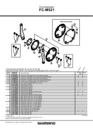
DESCRIPTION<br />
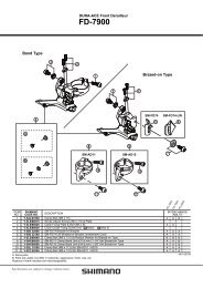
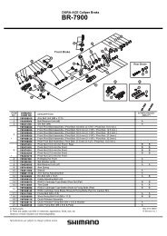
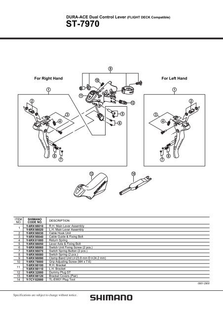
DURA-ACE Dual Control Lever (FLIGHT DECK Compatible)<br />
<strong>ST</strong>-<strong>7970</strong><br />
R.H. Main Lever Assembly<br />
L.H. Main Lever Assembly<br />
Cable Hook Unit<br />
Cable Guide & Fixing Bolt<br />
Return Spring<br />
Lever Axle & Fixing Bolt<br />
Switch Unit Fixing Screw (2 pcs.)<br />
Switch Spring Button (2 pcs.)<br />
Switch Spring (2 pcs.)<br />
Clamp Band Unit ( 23.8 mm Ð 24.2 mm)<br />
Grip Adjusting Screw (M4 x 7.6)<br />
R.H. Bracket<br />
L.H. Bracket<br />
Dummy Plug <strong>ST</strong><br />
Bracket Covers (Pair)<br />
TL-EW01 Plug Tool<br />
11<br />
9<br />
13 14<br />
6<br />
5<br />
12<br />
3<br />
4<br />
7<br />
8<br />
2<br />
0901-2900
General Safety Information<br />
Series<br />
Dual control lever<br />
Electric cable<br />
Battery / Battery charger<br />
Gears<br />
Front derailleur<br />
Front chainwheel<br />
Rear derailleur<br />
Freehub<br />
Cassette sprocket<br />
Chain<br />
Caliper brake<br />
WARNING<br />
• When the shifting switch is operated, the motor<br />
which drives the front derailleur will operate<br />
without stopping at the shifting lever position.<br />
Always be sure to remove the battery before<br />
carrying out installation and adjustment,<br />
otherwise your fingers may become stuck.<br />
• Obtain and read the service instructions carefully<br />
prior to installing the parts. Loose, worn or<br />
damaged parts may cause the bicycle to fall over<br />
and serious injury may occur as a result. We<br />
strongly recommend only using genuine Shimano<br />
replacement parts.<br />
• Obtain and read the service instructions carefully<br />
prior to installing the parts. If adjustments are not<br />
carried out correctly, the chain may come off and<br />
this may cause you to fall off the bicycle which<br />
could result in serious injury.<br />
• Use the <strong>ST</strong>-<strong>7970</strong> with the BR-7900. Do not use the<br />
BR-7900 in combination with previous <strong>ST</strong>I levers for<br />
road riding or with the BL-R770/ BL-R550 brake<br />
levers for flat handlebars, otherwise the braking<br />
performance provided will be much too strong.<br />
• Because of the characteristics of the carbon fiber<br />
material, you must never modify the levers,<br />
otherwise the lever may break and the brakes may<br />
no longer work as a result.<br />
• Before riding the bicycle, check that there is no<br />
damage such as carbon fiber peeling or cracking. If<br />
there is any damage, replace with a new part<br />
immediately without trying to repair the damage,<br />
otherwise the lever may break and the brakes may<br />
no longer work as a result.<br />
• Read these Technical Service Instructions carefully,<br />
and keep them in a safe place for later reference.<br />
3<br />
Note<br />
• RD-<strong>7970</strong>: Be sure to adjust the top<br />
adjustment bolt and the low adjustment<br />
bolt by following the procedures in the<br />
Service Instructions. If these bolts are not<br />
adjusted, the chain may become clamped<br />
between the spokes and the large<br />
sprocket and the wheel may lock, or the<br />
chain may slip onto the small sprocket.<br />
• Use a soft cloth to clean the carbon fiber<br />
levers, and be sure to moisten the cloth<br />
with neutral detergent before using it,<br />
otherwise the lever material may become<br />
damaged and lose its strength.<br />
• Avoid leaving the carbon fiber levers in<br />
places where high temperatures are<br />
present. Also keep them well away from<br />
fire.<br />
• Operation of the levers related to gear<br />
shifting should be made only when the<br />
front chainwheel is turning.<br />
• Always be sure to use the TL-EW01<br />
special tool to remove the cable.<br />
• Be careful not to let water get into the<br />
terminal.<br />
• Parts are not guaranteed against natural<br />
wear or deterioration resulting from<br />
normal use.<br />
• For maximum performance we highly<br />
recommend Shimano lubricants and<br />
maintenance products.<br />
• For any questions regarding methods of<br />
installation, adjustment, maintenance or<br />
operation, please contact a professional<br />
bicycle dealer.<br />
In order to realize the best performance, we recommend that the following combination<br />
be used.<br />
DURA-ACE<br />
<strong>ST</strong>-<strong>7970</strong><br />
EW-<strong>7970</strong>/7972/7973/7975, SM-EW79A<br />
SM-BTR1 / SM-BCR1<br />
20<br />
FD-<strong>7970</strong><br />
FC-7900<br />
RD-<strong>7970</strong><br />
FH-7900<br />
CS-7900 (Except for 11-28T)<br />
CN-7900<br />
BR-7900<br />
English
Gear shifting operation<br />
Rear shifting switch operation<br />
< Shifting switch (X) ><br />
The chain moves from a small sprocket to a larger<br />
sprocket each time the switch is operated.<br />
Front shifting switch operation<br />
< Shifting switch (X) ><br />
Shifting switch (X)<br />
The chain moves from the small chainring to the<br />
large chainring.<br />
4<br />
< Shifting switch (Y) ><br />
The chain moves from a large sprocket to a smaller<br />
sprocket each time the switch is operated.<br />
The checker (SM-EC79) can be used to shift up and shift down shifting switches (X) and (Y).<br />
* For details on the shifting switch selection method, refer to the Service Instructions for the checker.<br />
Shifting switch (X)<br />
If the chain falls off on the inside, keep pressing<br />
shifting switch (X) to move the front derailleur to<br />
the outermost position in order to reset the chain.<br />
< Shifting switch (Y) ><br />
Shifting switch (Y)<br />
The chain moves from the large chainring to the<br />
small chainring.<br />
Shifting switch (Y)
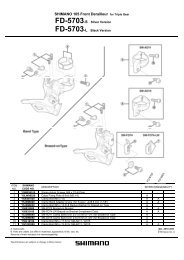
Installation<br />
Installation to the handlebars<br />
Wind the bracket cover from the front, and then use<br />
a 5 mm Allen key to tighten the mounting nut in<br />
order to secure the bracket cover.<br />
When installing the components to carbon<br />
frame/handle bar surfaces, verify with the<br />
manufacturer of the carbon frame/parts for their<br />
recommendation on tightening torque in order to<br />
prevent over tightening that can cause damage to<br />
the carbon material and/or under tightening that can<br />
cause lack of fixing strength for the components.<br />
Installation of the brake cables<br />
Cables used<br />
• Inner cable (PTFE inner cable) • • • • • • 1.6 mm dia.<br />
• SLR outer casing • • • • • • • • • • • • • • • • • • • 5 mm dia.<br />
Use cables which are long enough so that they still have<br />
some slack even when the handlebars are turned as far as<br />
they will go to the left and to the right.<br />
1. Gently pull the brake lever.<br />
2. Pass the inner cable through from<br />
directly in front, set the inner<br />
cable end into the cable hook,<br />
and then install the outer casing<br />
from the opposite side.<br />
The lever stroke can be smoothly<br />
adjusted using the bolt on the top<br />
of the bracket unit. Check the<br />
lever operation while adjusting.<br />
5<br />
Bracket cover<br />
5 mm Allen key<br />
Tightening torque:<br />
6 - 8 N·m {52 - 69 in. lbs.}<br />
Outer casing<br />
Cable hook<br />
Inner cable drum<br />
* Refer to the Service Instructions for the electric cables when connecting and routing the electric cables.
Adjustment<br />
Adjustment of the rear derailleur (RD-<strong>7970</strong>)<br />
1. Install the battery.<br />
2. Shift the rear derailleur to the 5th sprocket position.<br />
Press the button at the junction (A)<br />
of the SM-EW79A until the red LED<br />
turns on in order to switch to rear<br />
derailleur adjustment mode.<br />
Note that if you keep pressing the<br />
button after the red LED has<br />
turned on, protection recovery<br />
operation will begin.<br />
* Refer to the Service Instructions for the rear derailleur for details<br />
on the protection function.<br />
3. If shifting switch (X) is pressed once, the guide pulley will move<br />
one step toward the inside.<br />
If shifting switch (Y) is pressed once, the guide pulley will move<br />
one step toward the outside.<br />
The guide pulley can move 12 steps inward and 12 steps outward<br />
from the initial position, for a total of 25 positions.<br />
When adjusting, the guide pulley will overrun slightly and then move back in an exaggerated movement so<br />
that you can check the adjustment direction.<br />
When checking the positions of the guide pulley and the sprocket, check at the position where the guide<br />
pulley finally stops.<br />
6<br />
Janction (A)<br />
Button<br />
illuminates red
4. While turning the crank arm, operate shifting switch (X) to move<br />
the guide pulley toward the inside until the chain touches the 4th<br />
sprocket and makes a slight noise.<br />
Next, operate shifting switch (Y) 4 times to move the guide pulley<br />
toward the outside by 4 steps to the target position.<br />
4 steps<br />
Press the button at junction (A) until the red LED turns<br />
off in order to switch from rear derailleur adjustment<br />
mode to gear shifting mode.<br />
Shift to each gear and check that no noise is generated<br />
at any gear position.<br />
If fine adjustment is needed, switch back to adjustment<br />
mode and readjust the rear derailleur.<br />
7<br />
Button<br />
Operate 4 times<br />
Turned off
5. Next, carry out the adjustments for the low<br />
adjustment bolt and top adjustment bolt.<br />
< Low adjustment ><br />
Shift the rear derailleur to the largest sprocket,<br />
and then tighten the low adjustment bolt until it<br />
touches the stopper.<br />
< Top adjustment ><br />
Shift the rear derailleur to the smallest sprocket,<br />
and then tighten the top adjustment bolt until it<br />
touches the stopper at the position where the rear<br />
derailleur finally stopped.<br />
From this position, turn the top adjustment bolt<br />
counterclockwise one turn so that an over-stroke<br />
allowance can always be maintained.<br />
Top adjustment bolt<br />
By shifting from the largest sprocket to the<br />
smallest sprocket, the rear derailleur will<br />
move toward the outside by the over-stroke<br />
allowance and then move back.<br />
8<br />
2 mm Allen key<br />
Low adjustment bolt<br />
2 mm Allen key
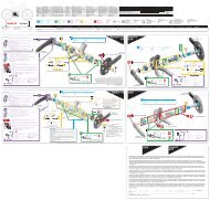
6. B-tension adjustment bolt adjustment<br />
Set the chain onto the small chainring and the<br />
largest sprocket, and then turn the crank arm<br />
backward.<br />
Turn the B-tension adjustment bolt to adjust so<br />
that the guide pulley moves close to the sprocket<br />
without obstructing the chain.<br />
Next, set the chain onto the smallest sprocket and<br />
check in the same way that the guide pulley does<br />
not obstruct the chain.<br />
Adjustment of the front derailleur (FD-<strong>7970</strong>)<br />
WARNING<br />
When the shifting switch is operated, the motor<br />
which drives the front derailleur will operate without<br />
stopping at the shifting lever position.<br />
Always be sure to remove the battery before carrying<br />
out installation and adjustment, otherwise your<br />
fingers may become stuck.<br />
Note:<br />
The low adjustment bolt, the top adjustment bolt and the<br />
support bolt are close to each other. Make sure that you<br />
are using the correct bolt for adjustment.<br />
< Low adjustment ><br />
Set the chain onto the small chainring and the largest<br />
sprocket.<br />
Use a 2 mm Allen key to turn the low adjustment bolt<br />
to adjust so that there is a clearance of 0.5 - 1 mm<br />
between the chain and the chain guide inner plate.<br />
9<br />
Largest sprocket<br />
Guide pulley<br />
Low adjustment bolt<br />
Smallest sprocket<br />
0.5 – 1 mm<br />
Adjustment<br />
B-tension<br />
adjustment bolt<br />
Support bolt<br />
Top adjustment bolt
Top adjustment ><br />
Next, set the chain onto the large chainring and the<br />
smallest sprocket.<br />
Use a 2 mm Allen key to turn the top adjustment bolt<br />
to adjust so that there is a clearance of 0.5 - 1 mm<br />
between the chain and the chain guide outer plate.<br />
Move the front derailleur and the rear derailleur to all<br />
gear positions, and check that the chain guide does not<br />
touch the chain.<br />
Other lever operation functions<br />
< Battery charge indicator ><br />
Press and hold either shifting switch for 0.5 seconds or more.<br />
You can check the amount of battery charge remaining using the<br />
battery indicator on top of junction (A).<br />
Battery indicator<br />
100 % Illuminates green (for 2 seconds)<br />
50 % Flashes green (5 times)<br />
25 % Illuminates red (for 2 seconds)<br />
0 % Flashes red (5 times)<br />
10<br />
0.5 – 1 mm<br />
Adjustment<br />
* When the battery charge is low, first the front derailleur will stop operating, and then the rear derailleur will<br />
stop operating. When the battery is fully spent, the derailleurs will stop at the positions where they were last<br />
shifted to. If the battery indicator is illuminated red, it is recommended that you recharge the battery as<br />
soon as possible.
Maintenance<br />
* The illustrations show the right-side lever.<br />
Disassembly of the bracket unit and lever unit<br />
1. Use a 2 mm Allen key to remove the lever shaft fixing<br />
screw at the bottom of the bracket unit.<br />
2. Tap an Allen key or similar tool with a plastic mallet to<br />
push out the lever shaft.<br />
3. Remove the return spring.<br />
Return spring<br />
11<br />
Lever shaft fixing screw<br />
Lever shaft
4. Remove the two switch unit fixing screws, and then remove the<br />
switches and the switch springs. The bracket unit and the lever unit<br />
can then be disassembled.<br />
Switch unit fixing screws<br />
(#T5 TORX® *)<br />
* TORX is a registered trademark<br />
of Camcar LLC.<br />
Assembly of the switch unit<br />
1. Check that the buttons are attached to the springs, and then place<br />
the switch springs into the holes in the switch lever setting plate.<br />
Switch springs<br />
2. Place the switch unit against the mounting surface of the switch<br />
unit setting plate.<br />
12<br />
DURA-ACE grease<br />
(Y-04110000)<br />
Apply grease
3. Press the switch unit by hand so that the switch springs go into the<br />
grooves in the buttons, and then push the shifting switches (X and Y)<br />
in as far as they will go.<br />
4. Make a gap between the switch unit and the<br />
switch unit setting plate and check that the end of<br />
the rubber on the switch unit is on the button.<br />
5. Return the switch unit to the setting position for<br />
the switch unit setting plate, and while pressing it<br />
by hand, operate the shifting switches (X and Y)<br />
once more and check that the switches turn on.<br />
Install the switch using the switch unit fixing<br />
screws.<br />
Shifting switches (X and Y)<br />
13<br />
Switch unit<br />
Tightening torque:<br />
0.18 N·m {1.5 in. lbs.}<br />
Maintenance
Assembly of the bracket unit and lever unit<br />
1. Assemble the bracket unit and the lever unit, attach the return<br />
spring, and then press-fit the lever shaft so that it is facing in<br />
the correct direction. Then tighten the lever shaft fixing screw<br />
to secure the lever shaft.<br />
Apply grease<br />
DURA-ACE grease<br />
(Y-04110000)<br />
Note:<br />
Tighten the lever shaft fixing<br />
screw so that it is flush with<br />
the bracket as shown in the<br />
illustration.<br />
14<br />
Maintenance<br />
* Operate the shifting switches (X and Y) and check that they turn on, and check that the lever operates<br />
smoothly.
One Holland, Irvine, California 92618, U.S.A. Phone: +1-949-951-5003<br />
Industrieweg 24, 8071 CT Nunspeet, The Netherlands Phone: +31-341-272222<br />
3-77 Oimatsu-cho, Sakai-ku, Sakai-shi, Osaka 590-8577, Japan<br />
* Service Instructions in further languages are available at :<br />
http://techdocs.shimano.com<br />
Please note: specifications are subject to change for improvement without notice.<br />
© Apr. 2010 by Shimano Inc. XBC IZM Printed in Japan