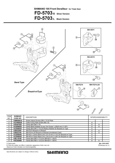
SHIMANO 105 Front Derailleur for Triple Gear - Canyon
SHIMANO 105 Front Derailleur for Triple Gear - Canyon
SHIMANO 105 Front Derailleur for Triple Gear - Canyon

Create successful ePaper yourself
Turn your PDF publications into a flip-book with our unique Google optimized e-Paper software.
SI-5LX0B-001-00<br />
General Safety In<strong>for</strong>mation<br />
WARNING<br />
• Obtain and read the service instructions carefully prior<br />
to installing the parts. Loose, worn or damaged parts<br />
may cause the bicycle to fall over and serious injury may<br />
occur as a result. We strongly recommend only using<br />
genuine Shimano replacement parts.<br />
• Obtain and read the service instructions carefully prior<br />
to installing the parts.If adjustments are not carried out<br />
correctly, the chain may come off and this may cause you<br />
to fall off the bicycle which could result in serious injury.<br />
• Be careful not to let the cuffs of your clothes get caught in<br />
the chain while riding, otherwise you may fall off the<br />
bicycle.<br />
• Read these Technical Service Instructions carefully, and<br />
keep them in a safe place <strong>for</strong> later reference.<br />
Note<br />
• If gear shifting operations cannot be carried out smoothly,<br />
clean the derailleur and lubricate all moving parts.<br />
• If the amount of looseness in the links is so great that<br />
adjustment is not possible, you should replace the<br />
derailleur.<br />
• Use the CN-7801 / CN-6600 / CN-5600 with the FD-6703<br />
/ FD-5703.<br />
• When the chain is in the position shown in the illustration,<br />
the chain may contact the front chainrings or front<br />
derailleur and generate noise.<br />
If the noise is a problem, shift the chain onto the nextlarger<br />
rear sprocket or the one after.<br />
<strong>Front</strong><br />
chainrings<br />
Rear<br />
sprockets<br />
• For smooth operation, use the specified outer casing and<br />
the bottom bracket cable guide.<br />
• Grease the inner cable and the inside of the outer casing<br />
be<strong>for</strong>e use to ensure that they slide properly.<br />
• This front derailleur is <strong>for</strong> triple front chainwheel use only.<br />
It cannot be used with the double front chainwheel, as the<br />
shifting points do not match.<br />
• Parts are not guaranteed against natural wear or<br />
deterioration resulting from normal use.<br />
• For maximum per<strong>for</strong>mance we highly recommend<br />
Shimano lubricants and maintenance products.<br />
• For any questions regarding methods of installation,<br />
adjustment, maintenance or operation, please contact a<br />
professional bicycle dealer.<br />
Technical<br />
Service Instructions SI-5LX0B-001<br />
FD-6703 / FD-5703<br />
<strong>Front</strong> derailleur<br />
One Holland, Irvine, Cali<strong>for</strong>nia 92618, U.S.A. Phone: +1-949-951-5003<br />
Industrieweg 24, 8071 CT Nunspeet, The Netherlands Phone: +31-341-272222<br />
3-77 Oimatsu-cho, Sakai-ku, Sakai-shi, Osaka 590-8577, Japan<br />
* Service Instructions in further languages are available at :<br />
http://techdocs.shimano.com<br />
Please note: specifications are subject to change <strong>for</strong> improvement without notice. (English)<br />
© Dec. 2009 by Shimano Inc. XBC SZK Printed in Japan.<br />
In order to realize the best per<strong>for</strong>mance, we recommend that the following<br />
combination be used.<br />
Series ULTEGRA<br />
Shifting lever<br />
ST-6703<br />
Outer casing SP41<br />
<strong>Gear</strong>s 30<br />
<strong>Front</strong> derailleur FD-6703<br />
<strong>Front</strong> chainwheel FC-6703<br />
Rear derailleur RD-6700<br />
Freehub FH-6700<br />
Cassette sprocket CS-6700<br />
Chain<br />
Bottom bracket cable guide<br />
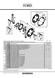
Specifications<br />
CN-7801 / CN-6600 / CN-5600<br />
SM-SP17<br />
Series ULTEGRA <strong>105</strong><br />
Type Band type / Brazed on type<br />
<strong>Front</strong> chainwheel tooth difference 22 teeth or less 20 teeth or less<br />
Min. difference between top and<br />
intermediate<br />
<strong>Front</strong> derailleur<br />
installation band diameter<br />
<strong>Front</strong> shifting<br />
13T 11T<br />
S (ø28.6mm),<br />
M (ø31.8mm), L (ø34.9mm)<br />
Chainstay angle (C) 63° - 66°<br />
Chain line 45mm<br />
Lever a<br />
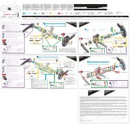
Installation of the front derailleur<br />
Adjust and then install the front derailleur as shown in the illustration.<br />
Do not remove the Pro-Set alignment block at this time.<br />
<strong>Gear</strong> teeth should<br />
come within this<br />
range<br />
Pro-Set gauge<br />
The level section of the chain guide outer plate should be<br />
directly above and parallel to the largest chainring.<br />
Secure using a 5mm Allen key.<br />
Tightening torque:<br />
5 - 7 N·m {44 - 60 in. lbs.}<br />
Lever b<br />
1mm<br />
3mm<br />
Lever b<br />
From large chainring<br />
to small chainring<br />
Lever a<br />
From small chainring<br />
to large chainring<br />
Pro-Set alignment block<br />
<strong>105</strong><br />
ST-5703<br />
SP41<br />
30<br />
FD-5703<br />
FC-5703<br />
RD-5700<br />
FH-5700<br />
CS-5700<br />
SM-SP17<br />
Chainstay<br />
angle<br />
Chainwheel<br />
(largest chainring)<br />
Chain guide<br />
In the case of carbon frames, it may be necessary to lower the tightening torque in order<br />
to prevent damage to the frame. Please consult the bicycle or frame manufacturer<br />
regarding the appropriate level of tightening torque <strong>for</strong>carbon frames.<br />
SIS adjustment<br />
Be sure to follow the sequence described below.<br />
1. Low adjustment<br />
First remove the Pro-Set alignment block. Next, set so<br />
that the clearance between the chain guide inner plate<br />
and the chain is 0 - 0.5mm.<br />
Chain position<br />
Largest<br />
sprocket<br />
Smallest<br />
chainring<br />
Pro-Set alignment block<br />
2. Connection and securing of cable<br />
While pulling the inner cable, tighten the wire fixing<br />
bolt with a 5 mm allen key to secure the cable.<br />
Tightening torque:<br />
6 - 7 N·m<br />
{52 - 60 in. lbs.}<br />
Pull<br />
After taking up the initial slack in the cable, re-secure<br />
to the front derailleur as shown in the illustration.<br />
3. Top adjustment<br />
Set so that the clearance between the chain guide<br />
outer plate and the chain is 0 - 0.5 mm.<br />
Chain position<br />
Smallest<br />
sprocket<br />
Chain guide<br />
inner plate<br />
Chain<br />
Largest<br />
chainring<br />
Low adjustment<br />
screw<br />
Top adjustment<br />
screw<br />
Chain guide<br />
outer plate<br />
Chain<br />
4. Cable adjustment using the intermediate chainring<br />
When making the cable adjustment, place the chain on the largest<br />
sprocket <strong>for</strong> the rear and the middle chainring <strong>for</strong> the front.<br />
Note: There are 2 derailleur positions <strong>for</strong> the intermediate chainring. When<br />
making the cable adjustment, make sure that the derailleur is in the<br />
inner side (toward small chainring) of the two positions. Locate the<br />
derailleur to this position by shifting from the largest to the<br />
intermediate chainring (recommended) or by shifting from the small to<br />
the intermediate chainring, then gently press lever (b) until a small<br />
click is felt (to position the derailleur to the inner side of the<br />
intermediate chainring).<br />
Adjust the cable tension by using the outer adjustment barrel so that<br />
the clearance between the chain guide inner plate and the chain is 0 -<br />
0.5 mm.<br />
B A<br />
Outer casing adjustment bolt<br />
Chain position<br />
Largest<br />
sprocket<br />
Intermediate<br />
chainring<br />
Chain guide<br />
inner plate<br />
Chain<br />
5. Trimming mechanism adjustment and checking<br />
While turning the crank arm, gently operate lever (b) and check that<br />
the front derailleur moves slightly toward the smallest chainring. If the<br />
front derailleur moves by a large amount and the chain is set onto the<br />
smallest chainring at this time, loosen the top adjustment bolt by 1/8th<br />
of a turn. Then, after returning the<br />
chain to its original position, adjust<br />
and check the trimming mechanism.<br />
Smallest<br />
sprocket<br />
Chain position<br />
Largest<br />
chainring<br />
Top adjustment<br />
screw<br />
Chain guide<br />
outer plate<br />
Chain<br />
6. Troubleshooting chart<br />
After completion of steps 1 - 5, move the shifting lever to check the<br />
shifting. (This also applies if shifting becomes difficult during use.)<br />
If the chain falls to the crank side<br />
If shifting is difficult from the intermediate<br />
chainring to the largest chainring<br />
If shifting is difficult from the intermediate<br />
chainring to the smallest chainring<br />
If there is interference between the chain<br />
and the front derailleur outer plate at the<br />
largest chainring<br />
If the intermediate chainring is skipped<br />
when shifting from the largest chainring<br />
If there is interference between the chain<br />
and front derailleur inner plate when the<br />
rear sprocket is shifted to the largest<br />
sprocket when the chainwheel is at the<br />
intermediate chainring position.<br />
If the chain falls to the bottom bracket<br />
side.<br />
Tighten the top adjustment screw<br />
clockwise (about 1/4 turn).<br />
Loosen the top adjustment screw<br />
counterclockwise (about 1/8 turn).<br />
Loosen the low adjustment screw<br />
counterclockwise (about 1/4 turn).<br />
Loosen the top adjustment screw<br />
counterclockwise (about 1/8 turn).<br />
Loosen the outer casing adjustment<br />
bolt counterclockwise (1 or 2 turns).<br />
Tighten the outer casing adjustment<br />
bolt clockwise (1 or 2 turns).<br />
Tighten the low adjustment screw<br />
clockwise (about 1/2 turn).<br />
Be sure to read these service instructions in conjunction with the service<br />
instructions <strong>for</strong> the ST-6703 / ST-5703 be<strong>for</strong>e use.
SI-5LW0B-001-00<br />
General Safety In<strong>for</strong>mation<br />
WARNING<br />
• Obtain and read the service instructions carefully prior to installing the parts.<br />
Loose, worn or damaged parts may cause the bicycle to fall over and serious injury<br />
may occur as a result. We strongly recommend only using genuine Shimano<br />
replacement parts.<br />
• Obtain and read the service instructions carefully prior to installing the parts.<br />
If adjustments are not carried out correctly, the chain may come off and this may<br />
cause you to fall off the bicycle which could result in serious injury.<br />
• Be careful not to let the cuffs of your clothes get caught in the chain while riding,<br />
otherwise you may fall off the bicycle.<br />
• Read these Technical Service Instructions carefully, and keep them in a safe place <strong>for</strong><br />
later reference.<br />
Note<br />
• If gear shifting operations cannot be carried out smoothly, clean the derailleur and<br />
lubricate all moving parts.<br />
• If the amount of looseness in the links is so great that adjustment is not possible, you<br />
should replace the derailleur.<br />
• When the chain is in the position shown in the illustration,<br />
the chain may contact the front chainrings or front derailleur<br />
and generate noise. If the noise is a problem, shift the chain<br />
onto the next-larger rear sprocket or the one after.<br />
• For smooth operation, use the specified outer casing and<br />
the bottom bracket cable guide.<br />
• Grease the inner cable and the inside of the outer casing<br />
be<strong>for</strong>e use to ensure that they slide properly.<br />
• Parts are not guaranteed against natural wear or deterioration resulting from normal<br />
use.<br />
• For maximum per<strong>for</strong>mance we highly recommend Shimano lubricants and<br />
maintenance products.<br />
• For any questions regarding methods of installation, adjustment, maintenance or<br />
operation, please contact a professional bicycle dealer.<br />
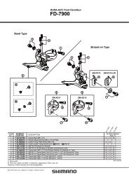
1. Adjust so that the clearance between the chain guide outer<br />
plate and the large gear is 1 - 3 mm be<strong>for</strong>e installing.<br />
2. The level section of the chain guide outer plate should be<br />
directly above and parallel to the largest chainring.<br />
3. Secure using a 5mm Allen key.<br />
One Holland, Irvine, Cali<strong>for</strong>nia 92618, U.S.A. Phone: +1-949-951-5003<br />
Tightening torque:<br />
5 - 7 N·m<br />
{44 - 60 in. lbs.}<br />
Chainwheel<br />
(largest chainring)<br />
Chain guide<br />
Industrieweg 24, 8071 CT Nunspeet, The Netherlands Phone: +31-341-272222 3-77 Oimatsu-cho, Sakai-ku, Sakai-shi, Osaka 590-8577, Japan<br />
* Service Instructions in further languages are available at : http://techdocs.shimano.com<br />
Please note: specifications are subject to change <strong>for</strong> improvement without notice. (English)<br />
© Dec. 2009 by Shimano Inc. XBC SZK Printed in Japan.<br />
<strong>Front</strong><br />
chainrings<br />
Rear<br />
sprockets<br />
Technical Service Instructions SI-5LW0B-001<br />
In order to realize the best per<strong>for</strong>mance, we recommend that the following<br />
combination be used.<br />
Series<br />
Shifting lever<br />
Outer casing<br />
<strong>Gear</strong>s<br />
<strong>Front</strong> derailleur<br />
<strong>Front</strong> chainwheel<br />
Rear derailleur<br />
Freehub<br />
Cassette sprocket<br />
Chain<br />
Bottom bracket cable guide<br />
Specifications<br />
FD-6700 / FD-5700<br />
<strong>Front</strong> derailleur<br />
Type Band type / Brazed on type<br />
<strong>Front</strong> derailleur installation band diameter S (28.6mm), M (31.8mm), L (34.9mm)<br />
<strong>Front</strong> chainwheel tooth difference 16 teeth or less<br />
Chainstay angle (C) 61° - 66°<br />
Chain line 43.5mm<br />
Installation of the front derailleur<br />
ULTEGRA<br />
ST-6700<br />
FD-6700<br />
FC-6700 / FC-6750<br />
RD-6700<br />
FH-6700<br />
CS-6700<br />
Chain guide outer plate<br />
In the case of carbon frames, it may be necessary to lower<br />
the tightening torque in order to prevent damage to the<br />
frame. Please consult the bicycle or frame manufacturer<br />
regarding the appropriate level of tightening torque <strong>for</strong>carbon<br />
frames.<br />
SP41<br />
20<br />
CN-7901 / CN-6701 / CN-5701<br />
SM-SP17<br />
<strong>105</strong><br />
ST-5700<br />
FD-5700<br />
FC-5700 / FC-5750<br />
RD-5700<br />
FH-5700<br />
CS-5700<br />
Clearance: 1 - 3 mm<br />
SIS adjustment<br />
1. Low adjustment<br />
Set so that the clearance between the chain guide inner<br />
plate and the chain is 0 - 0.5 mm.<br />
Largest<br />
sprocket<br />
Inner ring<br />
2. Connection and securing of cable<br />
While pulling the inner cable, tighten the wire fixing bolt with a 5 mm<br />
allen key to secure the cable.<br />
3. Top adjustment<br />
Set so that the clearance between the chain guide outer<br />
plate and the chain is 0 - 0.5 mm.<br />
Smallest<br />
sprocket<br />
Pull<br />
Outer ring<br />
4. Adjustment of the cable tension<br />
(1) Set the chain to the largest rear<br />
sprocket, and shift the front to<br />
top gear.<br />
Largest<br />
sprocket<br />
Outer ring<br />
(2) Per<strong>for</strong>m the trimming.<br />
(ST-6700 / ST-5700)<br />
Tightening torque:<br />
6 - 7 N·m {52 - 60 in. lbs.}<br />
Chain guide<br />
inner plate<br />
After taking up the initial slack in the cable,<br />
re-secure to the front derailleur as shown in<br />
the illustration.<br />
While turning the crank arm, gently operate lever (b) and check that the front derailleur<br />
moves slightly toward the small chainring. If the front derailleur moves by a large<br />
amount and the chain is set onto the small chainring at this time, loosen the top<br />
adjustment bolt by 1/8th of a turn. Then, after returning the chain to its original position,<br />
adjust and check the trimming mechanism.<br />
(3) After trimming, adjust the clearance<br />
(by using the cable-adjustment bolt)<br />
of the chain and chain guide to the<br />
minimum (0 - 0.5 mm).<br />
Largest<br />
sprocket<br />
Outer ring<br />
Lever [a<br />
Lever [b<br />
Chain<br />
Tighten the top adjustment screw clockwise<br />
(about 1/4 turn).<br />
Loosen the top adjustment screw<br />
counterclockwise (about 1/8 turn).<br />
Loosen the low adjustment screw<br />
counterclockwise (about 1/8 turn).<br />
Low adjustment<br />
screw<br />
Top adjustment<br />
screw<br />
Chain guide<br />
outer plate<br />
Chain<br />
■ Trimming (noise-prevention mechanism)<br />
Gently press the lever [b .<br />
(A “click” sound will be heard.)<br />
B A<br />
Outer casing adjustment bolt<br />
<strong>Front</strong> shifting<br />
Lever [b<br />
From large chainring<br />
to small chainring<br />
Lever [a<br />
From small chainring<br />
to large chainring<br />
Chain guide<br />
inner plate<br />
5. Troubleshooting chart<br />
After completion of steps 1 - 4, move the shifting lever to check the shifting.<br />
(This also applies if shifting becomes difficult during use.)<br />
If the chain falls to the crank side<br />
If shifting is difficult from the small chainring to the<br />
large chainring<br />
If shifting is difficult from the large chainring to the<br />
small chainring<br />
If the chain falls to the bottom bracket side.<br />
If the gear shifting to the small chainring is stiff and<br />
difficult to carry out after trimming.<br />
Chain<br />
Clearance:<br />
0 - 0.5mm<br />
Tighten the low adjustment screw clockwise<br />
(about 1/2 turn).<br />
Turn the outer casing adjustment bolt<br />
clockwise (1/8 of a turn at a time) until<br />
shifting to the small chainring becomes<br />
smooth. Be careful not to turn the outer<br />
casing adjustment bolt too far at this time,<br />
otherwise shifting to the large chainring will<br />
become more difficult.<br />
Be sure to read these service instructions in conjunction with the service instructions <strong>for</strong> the<br />
ST-6700 / ST-5700 be<strong>for</strong>e use.