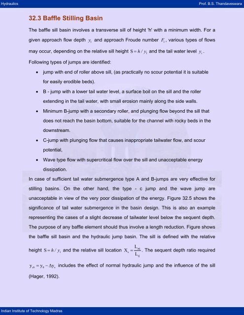
32.3 Baffle Stilling Basin - nptel - Indian Institute of Technology Madras
32.3 Baffle Stilling Basin - nptel - Indian Institute of Technology Madras
32.3 Baffle Stilling Basin - nptel - Indian Institute of Technology Madras

You also want an ePaper? Increase the reach of your titles
YUMPU automatically turns print PDFs into web optimized ePapers that Google loves.
Hydraulics Pr<strong>of</strong>. B.S. Thandaveswara<br />
<strong>32.3</strong> <strong>Baffle</strong> <strong>Stilling</strong> <strong>Basin</strong><br />
The baffle sill basin involves a transverse sill <strong>of</strong> height 'h' with a minimum width. For a<br />
given approach flow depth y 1 and approach Froude number F 1 , various types <strong>of</strong> flows<br />
may occur, depending on the relative sill height S = h/ y 1 and the tail water level y t .<br />
Following types <strong>of</strong> jumps are identified:<br />
<strong>Indian</strong> <strong>Institute</strong> <strong>of</strong> <strong>Technology</strong> <strong>Madras</strong><br />
• jump with end <strong>of</strong> roller above sill, (as practically no scour potential it is suitable<br />
for easily erodible beds).<br />
• B - jump with a lower tail water level, a surface boil on the sill and the roller<br />
extending in the tail water, with small erosion mainly along the side walls.<br />
• Minimum B-jump with a secondary roller, and plunging flow beyond the sill that<br />
does not reach the basin bottom, suitable for the channel with rocky beds in the<br />
downstream.<br />
• C-jump with plunging flow that causes inappropriate tailwater flow, and scour<br />
potential,<br />
• Wave type flow with supercritical flow over the sill and unacceptable energy<br />
dissipation.<br />
In case <strong>of</strong> sufficient tail water submergence type A and B-jumps are very effective for<br />
stilling basins. On the other hand, the type - c jump and the wave jump are<br />
unacceptable in view <strong>of</strong> the very poor dissipation <strong>of</strong> the energy. Figure 32.5 shows the<br />
significance <strong>of</strong> tail water submergence in the basin design. This is also an example<br />
representing the cases <strong>of</strong> a slight decrease <strong>of</strong> tailwater level below the sequent depth.<br />
The purpose <strong>of</strong> any baffle element should thus involve a length reduction. Figure shows<br />
the baffle sill basin and the hydraulic jump basin. The sill is defined with the relative<br />
height S = h/ y 1 and the relative sill location<br />
0 s<br />
X<br />
L<br />
srj<br />
s = . The sequent depth ratio required<br />
Lrj<br />
ysb = y −∆y<br />
includes the effect <strong>of</strong> normal hydraulic jump and the influence <strong>of</strong> the sill<br />
(Hager, 1992).
Hydraulics Pr<strong>of</strong>. B.S. Thandaveswara<br />
y1<br />
y1<br />
Lrj<br />
<strong>Indian</strong> <strong>Institute</strong> <strong>of</strong> <strong>Technology</strong> <strong>Madras</strong><br />
Lj<br />
h<br />
y2<br />
Classical hydraulic jump<br />
y2<br />
a) b)<br />
Adequate Tail waterproper<br />
formation <strong>of</strong> the jump<br />
and effective dissipation <strong>of</strong><br />
energy.<br />
y1<br />
y1<br />
Lsrj<br />
Ljb<br />
h<br />
xs bs<br />
c) d)<br />
h<br />
Inadequate Tail waterhence<br />
Submergence is<br />
wanting.<br />
xs = Lrj<br />
<strong>Baffle</strong> sill basin<br />
y2<br />
h<br />
y2<br />
Lsrj ____ h<br />
S = __<br />
,<br />
Figure 32.5 - Definition Sketch for <strong>Stilling</strong> basin with Sill<br />
( ) 2<br />
07 .<br />
∆ Y s = 07 . S + 3S 1−x<br />
s<br />
For any sill height h 1 , minimum approach Froude number F 1min is necessary for the<br />
formation <strong>of</strong> the hydraulic jump, and the corresponding maximum relative sill height S max<br />
for any approach flow Froude number is given by<br />
1 5/ 3<br />
S max = F1<br />
.<br />
6<br />
The relative sill height is normally limited to S max = 2 in practice. It may be noted that the<br />
sill should neither be too small nor too large.<br />
The optimum sill height S opt is<br />
1 25 .<br />
Sopt = 1+ F 1 .<br />
200<br />
y1
Hydraulics Pr<strong>of</strong>. B.S. Thandaveswara<br />
Depending mainly on the relative sill position X s three types <strong>of</strong> jump may form:<br />
I. A-jump X > 08 . ( to 1)<br />
II. B-jump 065 . < X > 08 .<br />
III. Minimum B-jump 055 . < X > 065 .<br />
<strong>Indian</strong> <strong>Institute</strong> <strong>of</strong> <strong>Technology</strong> <strong>Madras</strong><br />
s<br />
s<br />
s<br />
The length <strong>of</strong> the jump L jb from the toe to the end <strong>of</strong> the bottom roller relative to the<br />
Ljb<br />
1/ 3<br />
length <strong>of</strong> the classical jump L j is = 1−06 . S ( 1-Λ)<br />
.<br />
L<br />
j<br />
The length <strong>of</strong> the sill basin jump L jb is marginally less than the length <strong>of</strong> a classical jump<br />
L j for all three types <strong>of</strong> flows mentioned above. A sill basin improves the stabilization <strong>of</strong><br />
a hydraulic jump under variable tailwater and is somewhat shorter than a classical<br />
hydraulic jump.<br />
<strong>Baffle</strong> Block <strong>Basin</strong><br />
For optimum basin flow, the blocks must have an appropriate location and adequate<br />
height to overcome the ineffectiveness or overforcing <strong>of</strong> flow. Basco in 1971 defined the<br />
optimum height <strong>of</strong> the baffle as the ratio <strong>of</strong><br />
given by,<br />
S<br />
h<br />
=<br />
1<br />
opt<br />
opt<br />
y<br />
2<br />
( ) 16 75 F1 −<br />
L jb / h = . + .<br />
S opt<br />
opt<br />
1<br />
= 1+ F1−2 40<br />
( ) 2<br />
and the optimum basin length is<br />
Figure 32.6 shows the basin with the standard USBR blocks, where spacing <strong>of</strong> the<br />
blocks sp is equal to the block width sp= wband<br />
sp<br />
h<br />
= 075 . .
Hydraulics Pr<strong>of</strong>. B.S. Thandaveswara<br />
y<br />
<strong>Indian</strong> <strong>Institute</strong> <strong>of</strong> <strong>Technology</strong> <strong>Madras</strong><br />
1<br />
WB<br />
Xs<br />
a) Longitudinal section<br />
s<br />
p<br />
WB<br />
b) Standard baffles<br />
Figure- 32.6 Typical <strong>Baffle</strong> block basin<br />
A coefficient for representing the force on the blocks P B is given by<br />
Φ P / ⎡ρg w y / 2⎤<br />
2<br />
= B ⎣ b 2 ⎦<br />
for optimum basin performance, the coefficient Φ is<br />
F1<br />
1<br />
Φ opt = +<br />
7 100<br />
1/ 2<br />
⎛ 2 ⎞<br />
and the sequent depth ratio is Y b = ⎜ ⎟ F1−05 .<br />
⎝1+ Φ ⎠<br />
The tail water reduction is above 10% when compared to the classical jump. Type II,<br />
Type III and Type IV basins are shown below.<br />
y 2<br />
h
Hydraulics Pr<strong>of</strong>. B.S. Thandaveswara<br />
<strong>Indian</strong> <strong>Institute</strong> <strong>of</strong> <strong>Technology</strong> <strong>Madras</strong><br />
2y1 min<br />
0.8 y2<br />
Chute blocks<br />
Lb = 4.3 y2<br />
Fractional space<br />
Space = 2.5 w<br />
Lb = 6.1 y2<br />
<strong>Baffle</strong><br />
piers<br />
dentated sill<br />
(a) Type II basin F1 > 4.5<br />
v1 > 18.0 m/s Tail Water (TW) = 0.97 y2<br />
Chute<br />
blocks<br />
Fractional space<br />
h3 = y1(4+F1)/9<br />
End<br />
sill<br />
(b) Type III basin F1 > 4.5<br />
v1 < 18.0 m/s Tail Water (TW) = 0.83 y2<br />
(c) Type IV basin 2.5 F1 < 4.5<br />
Tail Water (TW) = y2<br />
Slope 2:1<br />
Sill optional<br />
h4 = y1(9+F1)/9<br />
h4 = y1(9+Fr1)/9