TCM120 Operation Manual
TCM120 Operation Manual
TCM120 Operation Manual

Create successful ePaper yourself
Turn your PDF publications into a flip-book with our unique Google optimized e-Paper software.
<strong>TCM120</strong><br />
<strong>Operation</strong> <strong>Manual</strong><br />
This manual covers operation of the tcm120, tcm121, tcm122, tcm123, tcm125, and the<br />
European version tcm121E. The term “tcm120” is used throughout this manual as the<br />
generic name for this family of temperature controllers. Likewise, the term “itc2200” is<br />
the generic name for a family of heating system cabinets that includes the itc2208,<br />
itc2216 and the itc2224.<br />
Revision Level 3.00<br />
March, 2000<br />
VTI, Incorporated<br />
24 McMillan Way<br />
Newark, DE 19713<br />
Phone (302) 738−0500<br />
FAX (302) 738−6594<br />
<strong>Manual</strong> No. 90001853
Table of Contents<br />
Introduction 1<br />
Module 1: Understanding the Function of the tcm120 2<br />
Module 2: Managing the tcm120: Powering Up, Shutting Down, and Moving 8<br />
Module 3: Reading the LEDs and the Display Screen 13<br />
Module 4: Using the tcm120 Keys 18<br />
Module 5: Accessing Parent Menus and Their Submenus 26<br />
Module 6: Responding to tcm120 Alarms 41<br />
Module 7: Commencing System Startup 52<br />
Appendix A: Changing the JP1 Jumper Configuration 60<br />
Appendix B: Guide to tcm120 Input and Output Options 61<br />
Appendix C: Guide to Maximum Heater Resistance<br />
62<br />
Appendix D: Guide to Self−Limiting Heating Cable Constants 65<br />
Appendix E: Default tcm120 Configuration Parameters 67<br />
Appendix F: Revisions 70
Introduction to the <strong>Manual</strong><br />
This manual is divided into seven modules. Each module includes a list of learning<br />
objectives, and some modules include exercises that provide an opportunity for you to<br />
practice the operations covered in the module.<br />
This manual assumes that you have a basic understanding of heating systems and heat<br />
monitoring terminology, and that you are familiar with the process that the tcm120<br />
monitors and controls.<br />
To use this manual, you need a tcm120 in front of you so that you can do the exercises in<br />
the modules. This tcm120 should be electrically powered, but it should not be attached<br />
to a heating zone. If you do not have a spare tcm120, disconnect the load from one<br />
tcm120 within your heating system so that you can complete the exercises in this tutorial.<br />
Note: The JP1 jumper configuration within the tcm120 hardware is factory−set at VTI<br />
and determines what functions you can perform on a particular tcm120. If an action is<br />
not permitted, the tcm120’s display screen shows the code ENBL. If the tcm120 you are<br />
using does not allow you to do an exercise in this tutorial, the JP1 jumper may need to<br />
be changed. For instructions on changing the JP1 jumper configuration, See Appendix<br />
A.<br />
Before proceeding with this manual, meet with the process engineer overseeing your<br />
operations to discuss what variables you will be monitoring and what functions you will<br />
be performing.<br />
After completing this manual, you will be able to<br />
> explain the information communicated on the front panel<br />
> use the keys to access data and set parameters<br />
> respond to alarms, and<br />
> commence system startup<br />
tcm120 <strong>Operation</strong> <strong>Manual</strong>/Rev. 3.00 3<br />
Introduction
Module 1<br />
Understanding the Function of the tcm120<br />
In this module, you learn the function of the tcm120 temperature controller and<br />
your role as an operator.<br />
Learning Objectives<br />
After completing this module, you will be able to<br />
> discuss the function of the tcm120 temperature controller<br />
> describe the itc2200 cabinet<br />
> describe the font panel of the tcm120<br />
tcm120 <strong>Operation</strong> <strong>Manual</strong>/Rev. 3.00 4<br />
Module 1
Introduction to the tcm120<br />
The tcm120 temperature controller is used to monitor and regulate individual heating<br />
circuits or zones within a heating system. The tcm120 helps prevent expensive damage<br />
to heating systems (such as heater damage due to groundfault currents) and freezing of<br />
process materials in pipes. The tcm120 alarms alert you when the heating zone is not<br />
operating within the desired parameters.<br />
For example, a tcm120 may be connected to a heating cable on a long pipeline that is at<br />
risk of freezing in winter. The tcm120 monitors and controls the temperature of the pipe.<br />
If the pipe’s temperature falls a pre−set amount below the set point (desired temperature),<br />
the tcm120 sets off a low temperature alarm to alert you.<br />
You can adjust the heating zone parameters to meet your particular application<br />
requirements. To make these adjustments, you use keys on the tcm120’s front panel to<br />
access one of the menus you will learn about in Modules 5 and 6. Through the menus,<br />
you can change the operating parameters of the heating zone and the tcm120, and enable<br />
and disable the alarms.<br />
As an operator, your primary task is to monitor the tcm120 and to respond to alarms. To<br />
respond to an alarm, you need to understand how to read the front panel of the tcm120<br />
and how to use the keys to access menus in the controller.<br />
tcm120 <strong>Operation</strong> <strong>Manual</strong>/Rev. 3.00 5<br />
Module 1
The tcm120:<br />
A Communication Center and Controller<br />
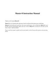
The tcm120 is a small computer that acts as a control and communication center between<br />
you and a heating zone. Figure 1 shows the communication flow between you and the<br />
heating zone through the tcm120.<br />
Data/Info Instructions<br />
Heating<br />
Zone Instructions tcm120 Data/Info You<br />
Figure 1.<br />
You can give instructions to the tcm120 to obtain information about the heating zone or<br />
to change the operating conditions of the heating zone.<br />
tcm120 <strong>Operation</strong> <strong>Manual</strong>/Rev. 3.00 6<br />
Module 1
The itc2200 Cabinet<br />
As shown in Figure 2, a tcm120 is positioned in an itc2200 cabinet with up to 23 other<br />
tcm120s. Depending on what model cabinet you are using, you may have one, two, or<br />
three racks. Each position in the racks is assigned an address (R1−1 through R3−8) that<br />
corresponds to the individual circuit breaker (CB1−1 through CB3−8) that controls<br />
power to the zone. Each itc2200 cabinet also has a main circuit breaker.<br />
Figure 2.<br />
tcm120 <strong>Operation</strong> <strong>Manual</strong>/Rev. 3.00 7<br />
Module 1
The tcm120’s Front Panel<br />
You can perform all functions from the front panel of the tcm120. As shown in Figure 3,<br />
the front panel contains a four digit alphanumeric display screen, 10 circular Light<br />
Emitting Diodes (LEDs), and six keys.<br />
Figure 3.<br />
The tcm120’s screen reveals information that the tcm120 has learned about the heating<br />
zone and displays new instructions as you enter them into the controller. Module 3<br />
explains the LEDs and their use. Module 4 explains the keys and their use.<br />
tcm120 <strong>Operation</strong> <strong>Manual</strong>/Rev. 3.00 8<br />
Module 1
tcm120 <strong>Operation</strong> <strong>Manual</strong>/Rev. 3.00 9<br />
Module 1
Module 2<br />
Managing the tcm120:<br />
Powering Up, Shutting Down and Moving<br />
In this module, you learn how to power up, shut down, and move a tcm120.<br />
Learning Objectives<br />
After completing this module, you will be able to<br />
> start up and shut down a tcm120<br />
> define three precautions necessary in handling a tcm120, and<br />
> move a tcm120<br />
tcm120 <strong>Operation</strong> <strong>Manual</strong>/Rev. 3.00 10<br />
Module 2
Powering Up the tcm120<br />
Because it is designed to run continuously, the tcm120 is powered up only at first use or<br />
if you need to turn it back on after power or equipment failure. Figure 4 shows the<br />
location of the main circuit breaker, which supplies power to the entire itc2200 cabinet,<br />
and the individual circuit breakers that are connected to individual tcm120s.<br />
Figure 4.<br />
Although you will learn in this module how to power up the tcm120, you should not<br />
actually start up your heating system until you have completed Modules 1−7. You will<br />
then be ready to operate a tcm120 that is connected to an actual heating zone. Module 7<br />
will walk you through starting up your system and answer common questions.<br />
tcm120 <strong>Operation</strong> <strong>Manual</strong>/Rev. 3.00 11<br />
Module 2
To power up the tcm120:<br />
1. Flip on the main circuit breaker, located at the bottom of the distribution section of<br />
the itc2200 cabinet.<br />
2. Flip on the individual circuit breakers, located in the distribution section of the<br />
itc2200 cabinet, for each tcm120 zone.<br />
The four−digit alphanumeric display lights up on each tcm102 after a few seconds,<br />
indicating that the tcm120 is powered up.<br />
(Note: Powering up may falsely trip the watch dog timer alarm or other alarms due to<br />
turn−on transients. Module 6 discusses how to respond to alarms.)<br />
Shutting Down the tcm120<br />
Because the tcm120 runs continuously, you will need to shut it down only for repair<br />
work.<br />
If repair work is taking place in a particular zone, always turn off the individual<br />
breaker for that zone.<br />
To shut down a single tcm120, flip off the individual circuit breaker, located in the<br />
distribution section of the itc2200 cabinet, for the zone you want to shut down.<br />
To shut down all tcm120s in the itc2200 cabinet:<br />
1. Flip off the individual circuit breakers, located in the distribution section of the<br />
itc2200 cabinet, for each tcm120 zone (24 breakers).<br />
2. Flip off the main circuit breaker, located at the bottom of the distribution section of<br />
the itc2200 cabinet.<br />
tcm120 <strong>Operation</strong> <strong>Manual</strong>/Rev. 3.00 12<br />
Module 2
Moving the tcm120<br />
Moving a tcm120 may become necessary<br />
> if a tcm120 malfunctions, or<br />
> if repair work is being done in the corresponding zone<br />
Handling electrical equipment is hazardous, so it is important to follow safety<br />
instructions carefully.<br />
Always turn the individual breaker off before removing, replacing, or inserting a<br />
tcm120.<br />
The tcm120 is sensitive to static when not enclosed in the itc2200 cabinet. To protect the<br />
tcm120 from static discharge, keep it wrapped in static free bubble packaging when it is<br />
not in the itc2200 cabinet.<br />
To avoid static shock, handle the tcm120 by picking it up with two hands, touching<br />
only the front panel and rear connector.<br />
Do not touch the components on the circuit board.<br />
Removing a tcm120<br />
To remove a tcm120:<br />
1. If the master circuit breaker is off, proceed to Step 3.<br />
2. If the master circuit breaker is on, you must turn off the individual circuit breaker<br />
corresponding to the particular tcm120.<br />
3. Remove the screws from the four corners of the front panel<br />
4. Remove the tcm120 from the rack by pulling on the handle located at the bottom of<br />
the front panel.<br />
tcm120 <strong>Operation</strong> <strong>Manual</strong>/Rev. 3.00 13<br />
Module 2
Inserting a tcm120<br />
To insert a new tcm120 or a tcm120 you have taken from another zone:<br />
1. If the master circuit breaker is off, proceed to Step 3.<br />
2. If the master circuit breaker is on, you must turn off the individual circuit breaker<br />
corresponding to the particular tcm120.<br />
3. Insert the tcm120 into the rack.<br />
4. Position the four screws on the corners of the front panel, and tighten them.<br />
Resetting Parameters<br />
Each of the tcm120’s operating parameters is preprogrammed by VTI prior to shipment<br />
for the particular specifications of the heating zone that the tcm120 is intended to control.<br />
The tcm120 has a small memory capacity that can remember these operating parameters<br />
even when it is unpowered. When a tcm120 is moved to a new zone, however, you<br />
consult with the process engineer to set up new parameters for that zone. Module 5<br />
explains how to change operating parameters.<br />
tcm120 <strong>Operation</strong> <strong>Manual</strong>/Rev. 3.00 14<br />
Module 2
Module 3<br />
Reading the LEDs and the Display Screen<br />
In this module, you learn what information is communicated by the two rows of<br />
circular Light Emitting Diodes (LEDs) on the tcm120’s front panel. You also learn<br />
about seven process variables that you can access from the front panel to monitor the<br />
heating zone.<br />
Learning Objectives<br />
After completing this module, you will be able to<br />
> name the LEDs in the top row and describe the function of each<br />
> name the LEDs in the bottom row and describe the function of each, and<br />
> explain the seven process variables that you can access from the front panel to<br />
monitor the heating zone<br />
tcm120 <strong>Operation</strong> <strong>Manual</strong>/Rev. 3.00 15<br />
Module 3
Reading the LEDs in the Top Row<br />
The five LEDs in the top row of the front panel correspond to important information<br />
about the heating zone, such as the present temperature, temperature deviation from the<br />
set point, and the voltage applied to the heating element. Figure 5 shows the position of<br />
the five LEDs in the top row.<br />
Figure 5.<br />
The display screen between the two rows of LEDs communicates values for the<br />
following five process variables of the heating zone when the corresponding LED is lit:<br />
Temp Present temperature of the heating zone in degrees Fahrenheit or degrees<br />
Celsius.<br />
T Dev Difference between the temperature of the zone and the desired<br />
temperature, called the set point (T Dev= Temp − Set Pt). A negative<br />
T Dev indicates that the zone’s temperature is less than the set point; a<br />
positive T Dev indicates that the zone’s temperature is greater than the<br />
set point.<br />
tcm120 <strong>Operation</strong> <strong>Manual</strong>/Rev. 3.00 16<br />
Module 3
Volt Voltage applied to the heating element.<br />
Cur Current flowing in the heating element.<br />
Set Pt Desired temperature or set point<br />
You will learn in Module 4 how to use the [INDEX] key to access the five LEDs in the<br />
top row to determine the corresponding value of the process variable for the zone you are<br />
monitoring.<br />
Two additional process variables, resistance and ground current, are also accessible from<br />
the front panel, even though there are no corresponding LEDs. The value shown on the<br />
screen when you access these process variables indicate the resistance or the ground<br />
current of the heating element, depending on which process variable you have selected.<br />
Module 4 explains how to use the [INDEX] key to access the resistance and ground<br />
current of the heater.<br />
tcm120 <strong>Operation</strong> <strong>Manual</strong>/Rev. 3.00 17<br />
Module 3
Reading the LEDs in the Bottom Row<br />
The LEDs in the bottom row also provide important information. Figure 6 shows the<br />
position of these LEDs.<br />
Figure 6.<br />
Man The amber LED in the center, Man, indicates whether the tcm120 is in<br />
manual or automatic mode.<br />
When the LED is lit, the controller is in manual. When the LED is not<br />
lit, the controller is in automatic mode. The controller usually remains<br />
in automatic mode, but you can use the manual mode to override the<br />
existing controller output voltage.<br />
tcm120 <strong>Operation</strong> <strong>Manual</strong>/Rev. 3.00 18<br />
Module 3
° F and ° C The green LEDs on either side of the Man LED indicate whether the<br />
displayed temperature is in Fahrenheit or in Celsius. Either the °F LED<br />
or the °C LED is always lit when the tcm120 is powered up.<br />
Alarm L The red LED at the left end of the row lights if the heating zone falls<br />
below a specified parameter.<br />
Alarm H The red LED at the right end of the row lights if the heating zone<br />
exceeds a specified parameter.<br />
tcm120 <strong>Operation</strong> <strong>Manual</strong>/Rev. 3.00 19<br />
Module 3
Module 4<br />
Using the tcm120 Keys<br />
In this module, you learn the functions of the six tcm120 keys, how to obtain<br />
information from the heating zone, and how to enter instructions into the tcm120.<br />
Learning Objectives<br />
After completing this module, you will be able to<br />
> define the purpose of each key<br />
> use the keys to monitor the temperature, temperature deviation, voltage,<br />
current, set point, resistance, and ground current, and<br />
> use the keys to change the voltage and set point<br />
tcm120 <strong>Operation</strong> <strong>Manual</strong>/Rev. 3.00 20<br />
Module 4
Using the Keys<br />
The six black keys positioned on the lower portion of the front panel allow you to<br />
monitor the heating zone and communicate instructions to it. Figure 7 shows the position<br />
of the six keys.<br />
Figure 7.<br />
tcm120 <strong>Operation</strong> <strong>Manual</strong>/Rev. 3.00 21<br />
Module 4
The keys are used for the following purposes:<br />
[INDEX] The [INDEX] key is used to move sequentially through the seven<br />
process variables you learned about in Module 3 and through the<br />
four parent menus (groups of submenus) that will be explained in<br />
Module 5.<br />
[q] and [p] The [q] and [p] keys have a variety of functions. They can<br />
decrease and or increase the value of the number showing on the<br />
display screen, or provide access to submenus from the parent<br />
menus. Module 5 explains submenus and parent menus.<br />
[ENTER] The [ENTER] key tells the tcm120 that you have finished creating<br />
a new instruction. Pressing the [ENTER] key prompts the tcm120<br />
to record the new data.<br />
[RESET] The [RESET] key has a dual function: it acknowledges alarms<br />
and also resets enabled alarms that require a manual reset. Module<br />
6 explains how to respond to alarms.<br />
[AUTO/MAN] The [AUTO/MAN] key allows you to toggle between auto and<br />
manual operation. Recall that the manual (or automatic) mode is<br />
indicated by the amber colored LED on the bottom row. In the<br />
automatic mode, the tcm120 controls the heater voltage to produce<br />
the exact amount of heat necessary to hold the zone temperature<br />
equal to the set point temperature. The manual mode allows you<br />
to change the heater voltage to whatever value you choose.<br />
tcm120 <strong>Operation</strong> <strong>Manual</strong>/Rev. 3.00 22<br />
Module 4
Exercise:<br />
In this exercise you will use the [INDEX] key to access the seven variables<br />
you learned about in Module 3.<br />
Press the [INDEX] key successively until the Temp LED lights up, as shown<br />
in Figure 8. You are now at the beginning of the process variable sequence.<br />
If your tcm120 is connected to a heating zone, the actual temperature of the<br />
heating zone is indicated on the display.<br />
Figure 8.<br />
Press the [INDEX] key again, and the T Dev LED lights up. Notice the<br />
temperature deviation indicted on the screen. The temperature deviation is<br />
the difference between the actual temperature of the heating zone (shown<br />
when the Temp LED is lit) and the set point (shown when the Set Pt LED is<br />
lit).<br />
tcm120 <strong>Operation</strong> <strong>Manual</strong>/Rev. 3.00 23<br />
Module 4
If your tcm120 is connected to a heating zone, the actual temperature deviation is<br />
indicated on the display.<br />
Press the [INDEX] key again, and the Volt LED lights up. Notice the<br />
voltage indicated on the screen in volts. The numbers on the screen may be<br />
changing constantly if the voltage being applied to the heating element is<br />
changing.<br />
Press the [INDEX] key again, and the Cur LED lights up. Notice the actual<br />
heating element current indicated in amps on the screen.<br />
Press the [INDEX] key again, and the Set Pt LED lights up. Notice the set<br />
point temperature indicated on the screen.<br />
Press the [INDEX] key again and notice that no LED lights up, as shown in<br />
Figure 9. Notice the resistance indicated in ohms on the screen: three<br />
numbers followed by an R.<br />
Figure 9.<br />
tcm120 <strong>Operation</strong> <strong>Manual</strong>/Rev. 3.00 24<br />
Module 4
Press the [INDEX] key again and notice that no LED lights up, as shown in<br />
Figure 10. Notice the ground current display in milliamps on the screen:<br />
three numbers followed by a G.<br />
Figure 10.<br />
Press the [INDEX] key four times until you see the Temp LED light up<br />
again. The three selections that follow the ground current process variable<br />
do not have LEDs. These selections are parent menus that you will learn<br />
about in Module 5.<br />
tcm120 <strong>Operation</strong> <strong>Manual</strong>/Rev. 3.00 25<br />
Module 4
Changing Voltage and Set Point<br />
All the process variables read information from the electrical heating zone and<br />
communicate it to you. You can also enter information into the electrical heating zone<br />
through the third and fifth process variables, Volt and Set Pt by using the keys on the<br />
front panel.<br />
To change the voltage, use the [INDEX] key to select the Volt process variable; then,<br />
press the [AUTO/MAN] key to access the manual mode. To decrease or increase the<br />
voltage, use the [q] and [p] keys. The voltage changes as the display changes; you do<br />
not need to press the [ENTER] key. To restore the automatic mode, press the<br />
[AUTO/MAN] key.<br />
To change the set point, use the [INDEX] key to select the Set Pt process variable. To<br />
decrease or increase the set point, use the [q] and [p] keys to change the displayed<br />
value. Then press the [ENTER] key to record the data. The tcm120 blinks to indicate it<br />
has accepted the data as the new set point.<br />
Exercise:<br />
In this exercise you will increase the heater voltage to full scale for maximum<br />
heat.<br />
Use the [INDEX] key to select Volt.<br />
Press the [AUTO/MAN] key to access the manual mode.<br />
Press the [p] key and hold it depressed until the voltage reaches full scale.<br />
When maximum heat is no longer needed, press the [AUTO/MAN] key to<br />
restore automatic mode. The tcm120 will resume controlling according to the<br />
set point temperature.<br />
tcm120 <strong>Operation</strong> <strong>Manual</strong>/Rev. 3.00 26<br />
Module 4
Exercise:<br />
In this exercise you will increase the set point by five degrees..<br />
Use the [INDEX] key to select Set Pt.<br />
Press the [p] key to increase the displayed value by five degrees.<br />
After obtaining the desired temperature in the display, press the [ENTER]<br />
key to enter the data.<br />
The tcm120 indicates it has accepted the data as the new set point by<br />
blinking.<br />
tcm120 <strong>Operation</strong> <strong>Manual</strong>/Rev. 3.00 27<br />
Module 4
Module 5<br />
Accessing Parent Menus and Their Submenus<br />
In this module, you learn the functions of the parent menus and how to access<br />
their submenus. You also learn the difference between numeric and discrete menus, and<br />
how to change operating parameters.<br />
Learning Objectives<br />
After completing this module, you will be able to<br />
> explain the functions of the three parent menus accessible to the operator<br />
> access these parent menus and their submenus,<br />
> define the difference between numeric and discrete menus, and<br />
> change operating parameters<br />
tcm120 <strong>Operation</strong> <strong>Manual</strong>/Rev. 3.00 28<br />
Module 5
Accessing the Parent Menus<br />
Three parent menus follow the ground current process variable. The parent menus do not<br />
have corresponding LEDs.<br />
(Note: a fourth parent menu, CALB, is not visible or accessible to the operator from the<br />
front panel. Access to the CALB parent menu, which allows calibration of internal<br />
tcm120 operating constants, is blocked by the JP1 jumper configuration. The tcm120 is<br />
factory−calibrated prior to shipment and does not normally require field calibration of<br />
operating constants in this parent menu. Only factory representatives or other qualified<br />
persons should alter the calibration settings in the CALB parent menu.)<br />
The parent menus can be accessed in sequence by pressing the [INDEX] key. When you<br />
access a parent menu, a four−letter abbreviation appears on the display screen.<br />
CNFG allows you to configure operating parameters<br />
CONT allows you to adjust control loop parameters<br />
ALRM allows you to select alarm actions and enter the alarm set points<br />
Each parent menus has a number of submenus. This module covers the submenus for the<br />
configuration (CNFG) and control (CONT) parent menus, with which you should be<br />
familiar. However, you will rarely use these menus, except as directed by the process<br />
engineer. The alarm (ALRM) parent menu and its submenus will be covered in Module<br />
6.<br />
tcm120 <strong>Operation</strong> <strong>Manual</strong>/Rev. 3.00 29<br />
Module 5
Submenus:<br />
Discrete versus Numeric<br />
Submenus—either discrete or numeric—define a particular parameter or command that you<br />
can change. A discrete submenu requires you to choose from a limited number of<br />
possible selections. A numeric submenu allows you to choose a value by decreasing or<br />
increasing the number on the display screen.<br />
In discrete submenus, press the [q] or [p] key to select the desired option. In numeric<br />
submenus, press the [q] or [p] key to decrease or increase the value. For both kinds of<br />
submenus, press [ENTER] to record the data. The tcm120 signals it has recorded the<br />
data by blinking.<br />
Accessing the Submenus<br />
The [INDEX] key allows you to move through the seven process variables and three<br />
parent menus to survey the information available to you about the heating zone or to<br />
access a parameter you want to change. To access the submenu list within a parent<br />
menu, press the [q] key. The first submenu will be displayed.<br />
To go to the next submenu, press the [INDEX] key. To enter any submenu, press the [q]<br />
key. Within a submenu, the [q] and [p] keys allow you to select either discrete or<br />
numeric options as previously discussed. To return to the parent menu after accessing<br />
the submenu options, press the [INDEX] key to return to the submenu loop; then press<br />
[p] to return to the parent menu.<br />
The charts on the following three pages show the location of the submenus within the<br />
CNFG, CONT, and ALRM parent menus.<br />
The exercises in Modules 5 and 6 offer an opportunity to practice using the [q] and [p]<br />
keys and the [INDEX] key to access the submenus.<br />
tcm120 <strong>Operation</strong> <strong>Manual</strong>/Rev. 3.00 30<br />
Module 5
MENU CHART 1 CNFG<br />
tcm120 <strong>Operation</strong> <strong>Manual</strong>/Rev. 3.00 31<br />
Module 5
MENU CHART 2 CONT<br />
tcm120 <strong>Operation</strong> <strong>Manual</strong>/Rev. 3.00 32<br />
Module 5
MENU CHART 3 ALRM<br />
tcm120 <strong>Operation</strong> <strong>Manual</strong>/Rev. 3.00 33<br />
Module 5
The CNFG Menu<br />
The configuration parent menu allows you or the process engineer to manipulate<br />
operating parameters. The menu contains 17 submenus.<br />
The following chart lists the submenus in the order they appear on the display screen<br />
when you access them. The second column explains the function of each submenu. The<br />
third column lists the options for discrete submenus and ranges for numeric submenus<br />
and ranges for numeric submenus.<br />
Submenu<br />
Submenu<br />
Function<br />
Function<br />
CNFG Parent Menu<br />
CNFG Parent Menu<br />
Discrete Submenu Options Or<br />
Numeric Submenu Ranges<br />
TEMP<br />
Sets temperature unit display. F – Fahrenheit<br />
C– Celsius<br />
TFB Sets source for temperature RTD – Resistance Temperature<br />
measurement.<br />
Device<br />
T/C – Thermocouple<br />
RES – Resistance Inference<br />
XMIT – Remote 4−20 mA<br />
Transmitter (see X4 and X20<br />
submenus for range selection)<br />
T/C Sets thermocouple type.<br />
J – Type J Thermocouple<br />
K – Type K Thermocouple<br />
X4 Sets temperature in degrees<br />
corresponding to the 4 mA signal<br />
from an external transmitter (cannot<br />
exceed limits set by RMIN and<br />
RMAX values.) X4< X20.<br />
Range : 0( C to 1300( C<br />
X20 Range : 0( C to 1300( C<br />
Sets temperature in degrees<br />
corresponding to the 20 mA signal<br />
from an external transmitter (cannot<br />
exceed limits set by RMIN and<br />
RMAX values.) X20 > X4.<br />
Discrete Submenu Options Or<br />
Numeric Submenu Ranges<br />
tcm120 <strong>Operation</strong> <strong>Manual</strong>/Rev. 3.00 34<br />
Module 5
RMIN Sets minimum temperature to be<br />
measured by the controller in<br />
Range : 0( C to 1300( C<br />
degrees. It is used internally to scale<br />
all temperature values. RMIN <<br />
RMAX<br />
RMAX<br />
Sets maximum temperature to be<br />
measured by the controller in<br />
Range : 0( C to 1300( C<br />
degrees. It is used internally to scale<br />
all temperature values. RMAX ><br />
RMIN.<br />
OUT Sets output selection. PHAS – Phase Controlled Output<br />
PRO – Time Proportioned Output<br />
REMI – Isolated 4−20 mA Output<br />
(Requires 4−20 mA output option<br />
to be installed. See X4 and X20<br />
submenus for range selection.)<br />
SP Sets source for process set point. LOC – Local Source, i.e., Front<br />
Panel<br />
COMP – Remote Source via<br />
Serial Interface; LOC locked out<br />
REMI – Remote 4−20 mA<br />
Transmitter (See X4 and X20<br />
submenus for range selection.)<br />
BAUD Sets baud rate for serial interface. 150 baud<br />
300 baud<br />
600 baud<br />
1200 baud<br />
1800 baud<br />
2400 baud<br />
4800 baud<br />
9600 baud<br />
tcm120 <strong>Operation</strong> <strong>Manual</strong>/Rev. 3.00 35<br />
Module 5
Submenu<br />
ILIM<br />
RNOM *<br />
CNFG Parent Menu<br />
Function<br />
Sets output current limit in amps<br />
(only effective if phase fired SCRs<br />
are used as output mode.)<br />
DEF Sets default display (activated<br />
when front panel operations not<br />
conducted for 15 minutes).<br />
REV Shows current software revision<br />
(cannot be changed from front<br />
panel).<br />
Discrete Submenu Options Or<br />
Numeric Submenu Ranges<br />
Range:<br />
0 to 20 amps for tcm120 series<br />
0 to 5 amps for tcm125, and<br />
0 to 25 amps for tcm121E.<br />
Sets default heater resistance in Normally set at 10 or at the<br />
ohms. Used by tcm120 in resistance approximate nominal resistance of<br />
inference mode whenever controller the heater when the heater is 50(<br />
output is
CNFG Parent Menu<br />
Submenu<br />
Function<br />
W0 Modeling constant for particular<br />
self−regulating heating cable being<br />
used (used in resistance inference<br />
mode only).<br />
W1 Modeling constant for particular<br />
self−regulating heating cable being<br />
used (used in resistance inference<br />
mode only).<br />
VMAX** Input power voltage to controller,<br />
usually 120, 208 or 240 volts<br />
Discrete Submenu Options Or<br />
Numeric Submenu Ranges<br />
As required. See Appendix D for<br />
details.<br />
As required. See Appendix D for<br />
details.<br />
Range 0 to 250 volts<br />
** The tcm120 cannot achieve full output because there will always be some voltage<br />
loss due to the tcm120’s solid state power switching device, the circuit breakers in<br />
the itc2200 cabinet, and the typical voltage loss through wiring that always occurs in<br />
an electrical system. Consequently, the maximum output voltage is 112 − 115 volts<br />
on a 120−volt system, 200 − 203 on a 208−volt system and 232−235 volts on a 240−<br />
volt system.<br />
tcm120 <strong>Operation</strong> <strong>Manual</strong>/Rev. 3.00 37<br />
Module 5
Exercise:<br />
In this exercise you will change the temperature scale from Fahrenheit to<br />
Celsius or vice versa.<br />
Access the CNFG parent menu.<br />
Press the [q] key to move to the submenu, TEMP.<br />
Press the [q] key again to enter the submenu, TEMP. You will see either F<br />
or C on your screen. The letter indicates the temperature scale that is<br />
presently used (Fahrenheit or Celsius, respectively).<br />
You can change F to C or C to F by pressing the [q] or [p] key. When you<br />
have selected the desired temperature scale, press [ENTER] to register it as<br />
the new temperature scale.<br />
The tcm120 indicates it has accepted the data by blinking. Note that the<br />
corresponding °F or °C LED on the front panel is now lit to indicate the new<br />
temperature scale.<br />
Press the [INDEX] key to exit the Temp submenu and go to the next<br />
submenu, TFB, within the CNFG parent menu..<br />
Press the [p] key to return to the CNFG parent menu.<br />
tcm120 <strong>Operation</strong> <strong>Manual</strong>/Rev. 3.00 38<br />
Module 5
Exercise:<br />
In this exercise, you will set the baud rate to 1200.<br />
Access the CNFG parent menu<br />
Press the [q] key to access the first submenu in the CNFG parent menu; then<br />
press the [INDEX] key to move to the submenu, BAUD.<br />
Press the [q] key to enter the BAUD submenu.<br />
Press the [q] or [p] key to move to 1200.<br />
Press [ENTER] to register 1200 as the new value.<br />
The tcm120 indicates it has accepted the data by blinking.<br />
Press the [INDEX] key to exit the BAUD submenu and to go the next<br />
submenu, ILIM, within the CNFG parent menu.<br />
Press the [p] key to return to the CNFG parent menu.<br />
The CONT Menu<br />
The control parent menu permits you or the process engineer to change control loop<br />
parameters. The tcm120 uses PID control when utilizing thermocouple, RTD, or remote<br />
transmitter temperature sensing. A proprietary algorithm is used for control when<br />
resistance inference temperature sensing is operating.<br />
There are actually two CONT parent menus within the tcm120 controller, one menu for<br />
the PID control algorithm and one menu for the proprietary algorithm. The menu is<br />
selected automatically by the tcm120. The selection is based on whether the controller is<br />
operating in resistance inference mode.<br />
Each<br />
tcm120 <strong>Operation</strong> <strong>Manual</strong>/Rev. 3.00 39<br />
Module 5
CONT parent menu contains six submenus. When resistance inference mode is<br />
operating, the submenus consist of a resistance calibration mode and five parameters.<br />
When resistance inference mode is not operating, the submenus consist of five<br />
parameters and an auto−tuning option. The parameters have numeric submenus. By<br />
pressing the [q] or [p] key, you can decrease or increase the value of the selected<br />
parameter. Pressing [ENTER] records the new value. Without direct instructions from<br />
the process engineer, the resistance calibration mode and the auto−tuning option are<br />
probably the only submenus you will use. However, you will use them infrequently, if at<br />
all.<br />
The following charts show the two CONT parent menus and their submenus in the order<br />
they appear on the display screen when you access them. The second column explains<br />
the function of each submenu. The third column lists the units in which the value is<br />
measured. The fourth column lists the options for discrete submenus and ranges for<br />
numeric submenus.<br />
Submenu<br />
CNFG Parent Menu #1<br />
Resistance Inference Mode<br />
Function Measured In<br />
RCAL Activates resistance calibration<br />
cycle<br />
YES *<br />
NO<br />
MOFF Adds manual offset to the set point Degrees Normally set to 0.<br />
Range: −199 to +199<br />
R0 Wire model constant. Should be set<br />
to 0.0 for current software revision.<br />
Used only in resistance inference<br />
mode.<br />
Discrete Submenu<br />
Options Or Numeric<br />
Submenu Ranges<br />
R1 Sets controller dead band. (Used in (C<br />
Normally set at 10.<br />
software revisions 0.20 and higher.)<br />
Used only in resistance inference<br />
Range: 3 to 50<br />
mode.<br />
R2 Not used with software revision<br />
0.03 and subsequent revisions.<br />
SLEW Sets output slew rate. Percent Per Normally set at 2.<br />
Second Range: 0 to 100<br />
* Used only to reactivate the resistance calibration mode for self−limiting cable if<br />
changes to heating circuit have been made since last calibration.<br />
tcm120 <strong>Operation</strong> <strong>Manual</strong>/Rev. 3.00 40<br />
Module 5
CNFG Parent Menu #2<br />
Not Resistance Inference Mode<br />
Submenu<br />
Function<br />
Measured In<br />
Discrete Submenu<br />
Options Or Numeric<br />
Submenu Ranges<br />
RATE Sets PID RATE (derivative) action. Seconds Normally set at 0.<br />
Range: 0 to 9999<br />
RST Sets PID reset (integral) action. Seconds Normally set at 600.<br />
Range: 0 to 9999<br />
PRO Sets PID gain (proportional) action. Degrees Normally set at 40.<br />
Range: 0 to 9999<br />
MOFF Adds manual offset to the set point Degrees Normally set at 0.<br />
Range: −199 to +199<br />
SLEW Sets output slew rate. Percent Per Normally set at 2.<br />
Second Range: 0 to 100<br />
TUNE Activates auto−tuning feature. YES<br />
NO<br />
PID loop parameters are sometimes sensitive to specific thermal characteristics of your<br />
heating zone. Auto turning a tcm120 in the field may polish its performance. To check<br />
whether the control loop parameters can be better tuned, use the auto−tuning feature.<br />
(The auto−tuning feature is not available when using resistance inference mode.)<br />
The auto−tuning feature is a discrete submenu with two options: YES and NO. To<br />
auto−tune the tcm120, press the [q] or [p] key to select YES. Press [ENTER] to record<br />
the information. Once set to YES the tcm120 switches immediately to the manual mode<br />
(the yellow Man LED lights up) and waits. You initiate an auto−tune cycle by pushing<br />
the [AUTO/MAN] button; the tcm120 enters an auto−tune sequence to adjust the<br />
RATE, RST, and PRO parameters for best possible control loop dynamics. The yellow<br />
Man LED on the front panel of the tcm120 blinks while the auto−tune cycle is in<br />
progress. The cycle can take several hours, depending on the thermal dynamics of your<br />
heating zone. When the cycle is complete, the controller switches to automatic mode.<br />
tcm120 <strong>Operation</strong> <strong>Manual</strong>/Rev. 3.00 41<br />
Module 5
Exercise:<br />
In this exercise, you will activate the auto−tuning mode to refine the<br />
parameters. (Remember: The auto tune option is available only in the<br />
second CONT menu. You will not be able to access it when the tcm120 is<br />
operating in resistance inference mode.)<br />
Access the CONT parent menu.<br />
Press the [q] key to access the first submenu in the CONT parent menu; then<br />
press the [INDEX] key to move to the submenu, TUNE.<br />
Press the [q] key to enter the TUNE submenu..<br />
Press the [q] or [p] key to select YES.<br />
Press [ENTER] to record the information.<br />
Once set to YES, the controller switches automatically to the manual mode<br />
(the yellow Man LED lights up). Start the auto−tuning sequence by pushing<br />
the [AUTO/MAN] button; the tcm120 initiates an auto−tune cycle to adjust<br />
the RATE, RST, and PRO parameters. The yellow Man LED on the front<br />
panel of the tcm120 blinks while the auto−tune cycle is in progress.<br />
Press the [INDEX] key to exit the TUNE submenu and go to the next<br />
submenu. (Because TUNE is the last submenu in the list, you return to the<br />
first submenu, RATE.)<br />
Press the [p] key to return to the CONT parent menu.<br />
The ALRM Menu<br />
The alarm parent menu allows you to select alarm actions and enter the alarm set points.<br />
Module 6 discusses the alarm parent menu in detail.<br />
tcm120 <strong>Operation</strong> <strong>Manual</strong>/Rev. 3.00 42<br />
Module 5
Module 6<br />
Responding to tcm120 Alarms<br />
In this module, you learn how to recognize and identify an alarm, and how to use<br />
your knowledge of the menus and keys to respond to an alarm.<br />
Learning Objectives<br />
After completing this module, you will be able to<br />
> respond to alarms<br />
> access the alarm menu and submenus<br />
> set parameters for alarms, and<br />
> enable and disable alarms<br />
tcm120 <strong>Operation</strong> <strong>Manual</strong>/Rev. 3.00 43<br />
Module 6
Responding to Alarms<br />
How often do alarms go off? If all equipment operates properly, the alarms should never<br />
go off. When alarms do go off, however, it is important to respond quickly. More than<br />
one alarm can go off at once. It does not matter to the tcm120 in what order you respond<br />
to alarms. However, some alarms could indicate more harm to your heating zone than<br />
other alarms; therefore, the more urgent fault conditions should be addressed first.<br />
When a tcm120 enters an alarm condition, the front panel LEDs for the high and/or low<br />
alarms light up and flash. To identify which of the 16 possible alarms are activated,<br />
select the Temp process variable on the front panel. The names of the activated alarms<br />
flash on the display screen, identifying the alarms so that you can take appropriate action.<br />
Whenever the Temp process variable is displayed, the alarm names will continue to<br />
flash until you clear the fault condition in the field and reset the alarms.<br />
To respond to an alarm, press the [RESET] key once to acknowledge the alarm. The<br />
alarm LED stops flashing, but remains lit until you correct the fault condition. If you do<br />
not correct the fault condition within four hours, the alarm reactivates and the alarm LED<br />
starts flashing again. If a new alarm occurs after you have acknowledged an activated<br />
alarm, the LED starts flashing again.<br />
If the alarm is configured for automatic reset, the alarm clears automatically and the LED<br />
turns off after you correct the fault condition. If the alarm is configured for manual reset,<br />
you must press the [RESET] key again to clear the alarm and return the LED to normal.<br />
In review, if an alarm goes off, follow these steps:<br />
1. Press the [RESET] key to acknowledge the alarm.<br />
2. Clear the fault condition.<br />
3. Press the [RESET] key to clear the alarm if it is configured for manual reset.<br />
Example: The T Dev LED of a tcm120 is lit, and the display screen shows a<br />
temperature deviation of −0.03. Suddenly, because the ground current<br />
exceeds its alarm set point, the Alarm H LED starts flashing.<br />
tcm120 <strong>Operation</strong> <strong>Manual</strong>/Rev. 3.00 44<br />
Module 6
Respond to the alarm as follows:<br />
Use the [INDEX] key to step to the Temp process variable display.<br />
(On the display, the alarm GFI alternates with the temperature.) Press<br />
the [RESET] key to acknowedge the alarm (the Alarm H LED will<br />
stop flashing). Correct the fault condition that created the alarm.<br />
When the condition has been corrected, the alarm will clear<br />
automatically if it is configured for automatic reset. If the alarm is<br />
configured for manual reset, you must press the [RESET] key again<br />
to clear the alarm.<br />
It is possible to completely disable alarms, but, in general, you should only disable<br />
alarms under unusual or extenuating circumstances. After all, the<br />
purpose of an alarm is to notify you of a condition that requires<br />
correction.<br />
System Alarms<br />
Each tcm120 has two separate alarm relays. In the itc2200 cabinet, each alarm relay<br />
output is wired in parallel with the corresponding relay outputs from all other tcm120s.<br />
These outputs activate two system alarm relays to generate two overall heating system<br />
alarms. A third system alarm relay detects loss of power to the cabinet to ensure fail−<br />
safe system alarm operation. The outputs of these system alarm relays are available to<br />
you to activate an annunciator or to serve as an input to a DCS computer.<br />
Accessing the ALRM Submenus<br />
The alarm parent menu allows you to enable individual alarms (or, when appropriate,<br />
disable alarms), to select manual or automatic reset of specific alarms, to enter alarm set<br />
points, and to select the operation for the two alarm relays (see submenus K1 or K2 in<br />
the chart on the following pages). The alarm parent menu contains 27 submenus.<br />
Submenus for specifying alarm set points are numeric. Use the [q] and [p] keys to<br />
decrease or increase the set point; then press the [ENTER] key. The tcm120 signals it<br />
has recorded the data by blinking.<br />
Submenus for disabling or enabling alarms are discrete. Use the [q] and [p] keys to<br />
select the desired alarm mode; then press the [ENTER] key. The tcm120 signals it has<br />
recorded the data by blinking.<br />
The following chart lists the submenus, their functions, and the options for discrete<br />
submenus.<br />
tcm120 <strong>Operation</strong> <strong>Manual</strong>/Rev. 3.00 45<br />
Module 6
Submenu<br />
ALRM Parent Menu<br />
Function Comments<br />
AH Sets the alarm point in degrees for<br />
high temperature<br />
AHD Sets the alarm point in degrees for<br />
high temperature deviation.<br />
AL Sets the alarm point in degrees for<br />
low temperature.<br />
ALD Sets the alarm point in degrees for<br />
low temperature deviation.<br />
RHI Sets the alarm point in ohms for<br />
high heater resistance; detects an<br />
open heater or a high resistance<br />
connection in the heater circuit.<br />
Set as an absolute temperature that is<br />
independent of set point temperature.<br />
Set as a positive delta above the set point<br />
temperature: Dev = Temp − Set Pt<br />
Set as an absolute temperature<br />
independent of set point temperature.<br />
Set as a negative delta above the set point<br />
temperature: Dev = Temp − Set Pt<br />
Alarm also activated when heater<br />
resistance changes more than +20% in 2.5<br />
seconds.<br />
RLOW Sets the alarm point in ohms for low activated when heater resistance changes<br />
heater resistance; detects a shorted more than +20% in 2.5 seconds.<br />
heater or low selflimiting heater<br />
resistance.<br />
GFIS Sets the alarm point for ground fault Adjustable from 10ma to 100ma. Normally<br />
current, measured in milliamps. set at 30ma.<br />
TAMB Sets the alarm point in degrees for<br />
high ambient temperature (if air<br />
around tcm120 >85(C, damage to<br />
circuitry could result.<br />
OCS Sets alarm point in amps for the<br />
output overcurrent (amount of<br />
current flowing into zone.)<br />
Factory set at 85(C.<br />
Tcm120 series:<br />
Adjustable from 0 to 25 amps. Normally set<br />
at 22 amps.<br />
Tcm125:<br />
Adjustable from 0.5 to 6 amps. Normally set<br />
at 6 amps.<br />
Tcm121E:<br />
Adjustable from 0 to 28 amps. Normally set<br />
at 27.5 amps.<br />
tcm120 <strong>Operation</strong> <strong>Manual</strong>/Rev. 3.00 46<br />
Module 6
Submenu<br />
* Silicon Controlled Rectifier<br />
ALRM Parent Menu<br />
Function Discrete Submenu Options<br />
K1 Selects alarms assigned to the K1<br />
alarm relay.<br />
K2 Selects alarms assigned to the K2<br />
alarm relay.<br />
ALL – Activated by all enabled alarm<br />
conditions.<br />
HI – Activated by high temp alarms and<br />
ground fault alarm (HT, HTD, GFI).<br />
HI+ – Activated by high temp alarms,<br />
ground fault alarm, and any nontemperature<br />
related<br />
ALL –<br />
alarm.<br />
Activated by all enabled alarm<br />
conditions.<br />
LOW – Activated by low temp alarms (LT,<br />
LTD).<br />
LOW+ – Activated by low temp alarms,<br />
and any non−temperature related alarm.<br />
FUSE Disables or enables alarm for blown DIS – Disables alarm.<br />
fuse.<br />
A/DF – SCRs* will be disabled if alarm<br />
occurs; automatic reset<br />
A/EF – SCRs will not be disabled if alarm<br />
occurs; automatic reset<br />
M/DF – SCRs will be disabled if alarm<br />
occurs; manual reset required<br />
M/EF – SCRs will not be disabled if alarm<br />
occurs; manual reset required<br />
HAMB Disables or enables alarm for high<br />
ambient temperature<br />
DIS – Disables alarm.<br />
A/DF – SCRs will be disabled if alarm<br />
occurs; automatic reset<br />
A/EF – SCRs will not be disabled if alarm<br />
occurs; automatic reset<br />
M/DF – SCRs will be disabled if alarm<br />
occurs; manual reset required<br />
M/EF – SCRs will not be disabled if alarm<br />
occurs; manual reset required<br />
tcm120 <strong>Operation</strong> <strong>Manual</strong>/Rev. 3.00 47<br />
Module 6
* Silicon Controlled Rectifier<br />
Submenu<br />
ALRM Parent Menu<br />
Submenu Function<br />
HT Disables or enables alarm for high<br />
process temperature.<br />
HTD Disables or enables alarm for high<br />
process temperature deviation.<br />
LT Disables or enables alarm for low<br />
process temperature.<br />
LTD Disables or enables alarm for low<br />
process temperature deviation<br />
Function<br />
ALRM Parent Menu<br />
Discrete Submenu Options<br />
DIS – Disables alarm.<br />
A/DF – SCRs* will be disabled if alarm<br />
occurs; automatic reset<br />
A/EF – SCRs will not be disabled if alarm<br />
occurs; automatic reset<br />
M/DF – SCRs will be disabled if alarm<br />
occurs; manual reset required<br />
M/EF – SCRs will not be disabled if alarm<br />
occurs; manual reset required<br />
DIS – Disables alarm.<br />
A/DF – SCRs will be disabled if alarm<br />
occurs; automatic reset<br />
A/EF – SCRs will not be disabled if alarm<br />
occurs; automatic reset<br />
M/DF – SCRs will be disabled if alarm<br />
occurs; manual reset required<br />
M/EF – SCRs will not be disabled if alarm<br />
occurs; manual reset required<br />
Discrete Submenu Options<br />
tcm120 <strong>Operation</strong> <strong>Manual</strong>/Rev. 3.00 48<br />
Module 6
RESH Disables or enables alarm for high<br />
heater resistance.<br />
RESL Disables or enables alarm for low<br />
heater resistance.<br />
GFI Disables or enables alarm for<br />
ground fault<br />
OC Disables or enables alarm for<br />
overcurrent condition<br />
* Silicon Controlled Rectifier<br />
DIS – Disables alarm.<br />
A/DF – SCRs* will be disabled if alarm<br />
occurs; automatic reset<br />
A/EF – SCRs will not be disabled if alarm<br />
occurs; automatic reset<br />
M/DF – SCRs will be disabled if alarm<br />
occurs; manual reset required<br />
M/EF – SCRs will not be disabled if alarm<br />
occurs; manual reset required<br />
DIS – Disables alarm.<br />
A/DF – SCRs will be disabled if alarm<br />
occurs; automatic reset<br />
A/EF – SCRs will not be disabled if alarm<br />
occurs; automatic reset<br />
M/DF – SCRs will be disabled if alarm<br />
occurs; manual reset required<br />
M/EF – SCRs will not be disabled if alarm<br />
occurs; manual reset required<br />
DIS – Disables alarm.<br />
A/DF – SCRs will be disabled if alarm<br />
occurs; automatic reset<br />
A/EF – SCRs will not be disabled if alarm<br />
occurs; automatic reset<br />
M/DF – SCRs will be disabled if alarm<br />
occurs; manual reset required<br />
M/EF – SCRs will not be disabled if alarm<br />
occurs; manual reset required<br />
DIS – Disables alarm.<br />
A/DF – SCRs will be disabled if alarm<br />
occurs; automatic reset<br />
A/EF – SCRs will not be disabled if alarm<br />
occurs; automatic reset<br />
M/DF – SCRs will be disabled if alarm<br />
occurs; manual reset required<br />
M/EF – SCRs will not be disabled if alarm<br />
occurs; manual reset required<br />
tcm120 <strong>Operation</strong> <strong>Manual</strong>/Rev. 3.00 49<br />
Module 6
Submenu<br />
Function<br />
* Silicon Controlled Rectifier<br />
** Resistance Thermonic Device<br />
ALRM Parent Menu<br />
OT/C Disables or enables alarm for open<br />
thermocouple.<br />
SRTD Disables or enables alarm for<br />
shorted RTD.**<br />
ORTD Disables or enables alarm for open<br />
RTD.<br />
DATA Disables or enables alarm for data<br />
loss. (Data loss occurs when data<br />
ALRM Parent Menu<br />
tcm120 <strong>Operation</strong> <strong>Manual</strong>/Rev. 3.00 50<br />
Module 6<br />
Function<br />
Discrete Submenu Options<br />
DIS – Disables alarm.<br />
A/DF – SCRs* will be disabled if alarm<br />
occurs; automatic reset<br />
A/EF – SCRs will not be disabled if alarm<br />
occurs; automatic reset<br />
M/DF – SCRs will be disabled if alarm<br />
occurs; manual reset required<br />
M/EF – SCRs will not be disabled if alarm<br />
occurs; manual reset required<br />
DIS – Disables alarm.<br />
A/DF – SCRs will be disabled if alarm<br />
occurs; automatic reset<br />
A/EF – SCRs will not be disabled if alarm<br />
occurs; automatic reset<br />
M/DF – SCRs will be disabled if alarm<br />
occurs; manual reset required<br />
M/EF – SCRs will not be disabled if alarm<br />
occurs; manual reset required<br />
DIS – Disables alarm.<br />
A/DF – SCRs will be disabled if alarm<br />
occurs; automatic reset<br />
A/EF – SCRs will not be disabled if alarm<br />
occurs; automatic reset<br />
M/DF – SCRs will be disabled if alarm<br />
occurs; manual reset required<br />
M/EF – SCRs will not be disabled if alarm<br />
occurs; manual reset required<br />
DIS – Disables alarm.<br />
A/DF – SCRs will be disabled if alarm<br />
stored in the configuration parameter occurs; automatic reset<br />
EEPROM is corrupted.)<br />
A/EF – SCRs will not be disabled if alarm<br />
occurs; automatic reset<br />
M/DF – SCRs will be disabled if alarm<br />
occurs; manual reset required<br />
M/EF – SCRs will not be disabled if alarm<br />
occurs; manual reset required
Submenu Discrete Submenu Options<br />
MAN Disables or enables alarm for<br />
manual mode.<br />
WDT Disables or enables the watch dog<br />
timer. (If program execution is<br />
interrupted for any reason, a watch<br />
dog timer will reboot the system.)<br />
* Silicon Controlled Rectifier<br />
Exercise:<br />
DIS – Disables alarm.<br />
A/DF – SCRs* will be disabled if alarm<br />
occurs; automatic reset<br />
A/EF – SCRs will not be disabled if alarm<br />
occurs; automatic reset<br />
M/DF – SCRs will be disabled if alarm<br />
occurs; manual reset required<br />
M/EF – SCRs will not be disabled if alarm<br />
occurs; manual reset required<br />
DIS – Disables alarm.<br />
A/DF – SCRs will be disabled if alarm<br />
occurs; automatic reset<br />
A/EF – SCRs will not be disabled if alarm<br />
occurs; automatic reset<br />
M/DF – SCRs will be disabled if alarm<br />
occurs; manual reset required<br />
M/EF – SCRs will not be disabled if alarm<br />
occurs; manual reset required<br />
tcm120 <strong>Operation</strong> <strong>Manual</strong>/Rev. 3.00 51<br />
Module 6
Exercise:<br />
In this exercise, you will increase the low temperature set point by five<br />
degrees.<br />
Select ALRM.<br />
Press the [q] key to access the first submenu in the ALRM parent menu; then<br />
press the [INDEX] key to move to the submenu, AL.<br />
Press the [q] key to enter the AL submenu.<br />
Use the [p] key to raise the set point by five degrees.<br />
Press the [ENTER] key to enter the data.<br />
The tcm120 indicates it has accepted the data by blinking.<br />
Press the [INDEX] key to exit the AL submenu and go to the next submenu,<br />
ALD.<br />
Press the [p] key to return the ALRM parent menu.<br />
tcm120 <strong>Operation</strong> <strong>Manual</strong>/Rev. 3.00 52<br />
Module 6
In this exercise, you will disable the GFI alarm.<br />
Select ALRM.<br />
Press the [q] key to access the first submenu in the ALRM parent menu; then<br />
press the [INDEX] key to move to the submenu, GFI.<br />
Press the [q] key to enter the GFI submenu.<br />
Press the [q] or [p] key to select DIS.<br />
Press the [ENTER] key to enter the data.<br />
The tcm120 indicates it has accepted the data by blinking.<br />
Press the [INDEX] key to exit the GFI submenu and move to the next<br />
submenu, OC.<br />
Press the [p] key to return the ALRM parent menu.<br />
tcm120 <strong>Operation</strong> <strong>Manual</strong>/Rev. 3.00 53<br />
Module 6
Module 7<br />
Commencing System Startup<br />
In the previous six modules, you have learned how to operate a tcm120. You are<br />
now ready to work with the process engineer to commence system startup. Module 7<br />
takes you through actual system startup, step−by−step.<br />
Learning Objectives<br />
After completing this module, you will be able to<br />
> start up the system<br />
> check the thermal system<br />
> check the field wiring<br />
> energize the transformer, and<br />
> energize the heating zones<br />
tcm120 <strong>Operation</strong> <strong>Manual</strong>/Rev. 3.00 54<br />
Module 7
Starting Up the System<br />
The startup procedure for the itc2200 heating system involves the following important<br />
steps:<br />
> checking the thermal system<br />
> checking and verifying field wiring<br />
> energizing the transformer<br />
> energizing each heating zone<br />
Checking the Thermal System<br />
The thermal characteristics of your heating system are just as important as the electrical<br />
controls in achieving overall system performance objectives. After installing the heating<br />
elements but before connecting them to an itc2200 system and before applying thermal<br />
insulation, complete the following steps:<br />
> Carefully inspect each heating element to make sure no physical damage has<br />
occurred during installation<br />
> Verify that good thermal contact has been achieved between each heating<br />
element and pipe or vessel.<br />
> Megger−test each lead of every heating element to exceed 20 Mohms to<br />
ground.<br />
> Energize each heating element to full rated voltage and measure the current.<br />
> Check the measured current against calculated design specifications.<br />
After thermal insulation is installed and carefully inspected for weatherproofing, each<br />
heating element should be energized again to full rated voltage. The measured current<br />
should be rechecked to design specification. Each lead of every heating element should<br />
also be megger−tested again to exceed 20 Mohms to ground.<br />
tcm120 <strong>Operation</strong> <strong>Manual</strong>/Rev. 3.00 55<br />
Module 7
Checking the Field Wiring<br />
Before any power is applied to the individual tcm120 controllers within the system, you<br />
should check and verify all field wiring by ensuring that the following steps have been<br />
completed:<br />
> The main power service to the transformer has been properly connected.<br />
> The itc2200 cabinet has been adequately grounded.<br />
> Each heating element has been correctly connected to the proper zone on the<br />
load terminal blocks (located in the distribution compartment).<br />
> The system alarm relay outputs, located at the bottom end of the load terminal<br />
blocks, have been wired to a DCS or annunciator panel.<br />
If the system is utilizing thermocouple or RTD temperature sensors, 4−20 mA remote<br />
inputs for set point or temperature feedback, or 4−20 mA outputs, you must verify the<br />
field wiring connections to the signal terminal blocks (located in the top compartment of<br />
the cabinet).<br />
Energizing the Transformer<br />
To ensure that adequate voltage is available to meet the heating system design<br />
requirements, energize the transformer and measure the secondary voltage following<br />
these steps:<br />
1. With the main circuit breaker and all zone circuit breakers within the itc2200<br />
cabinet turned off, energize the transformer.<br />
2. Measure the no−load secondary voltage to neutral (ground) on all three<br />
phases. (If the voltage is between +2.5% and +7.5% of the nominal system<br />
design value – 120 or 138 volts ac – then the proper secondary output tapes<br />
are being used.)<br />
3. If the measured secondary voltage of any phase does not fall between +2.5%<br />
and +7.5% of the nominal system design value, de−energize the transformer<br />
and use alternate secondary output taps, repeating steps 1−3 until the voltage<br />
is within these limits.<br />
tcm120 <strong>Operation</strong> <strong>Manual</strong>/Rev. 3.00 56<br />
Module 7
Energizing the Heating Zones<br />
To ensure proper operation, use the following steps to energize each heating zone<br />
individually and determine that each tcm120 operating correctly.<br />
1. With all zone circuit breakers in the itc2200 cabinet off, energize the<br />
transformer, and then turn on the main circuit breaker (the cooling fans will<br />
start).<br />
2. Turn on zone breaker CB1−1. This action energizes the tcm120 labeled R1−1<br />
and lights up its display screen and LEDs.<br />
3. If the tcm120 is configured for resistance inference mode temperature<br />
sensing, it starts up in the calibration cycle automatically, with the Temp LED<br />
flashing and the Man LED lit. The controller will not allow you to switch to<br />
automatic mode until you complete the temperature calibration sequence<br />
described in the next section. The completion of this procedure allows the<br />
tcm120 to properly measure or display process temperature and monitor or<br />
activate alarms related to process temperature. Therefore, while in the<br />
calibration sequence, the tcm120 temporarily disables HT, HTD, LT, LTD,<br />
and MAN alarms.<br />
(Note: all the menus and all other displayed values, such as voltage, current,<br />
set point, heater resistance, and ground current, are fully operational at all<br />
times. In addition, all alarms not related to temperature are operational, and<br />
therefore the tcm120 can indicate that alarms not related to temperature have<br />
tripped.)<br />
4. If the tcm120 is using thermocouple, RTD, or 4−20 mA remote inputs, no<br />
calibration is required. When the tcm120 is powered up, the front panel<br />
display immediately indicates the present state of the heating zone.<br />
Generally, one or both of the front panel alarm LEDs light up, and the display<br />
flashes the names of tripped alarms sequentially. Press the front panel reset<br />
key several times to clear any alarms falsely triggered due to turn−on<br />
transients. Any alarm that remains tripped is valid, and the fault causing the<br />
alarm must be addressed. Remember that at power up, the heating zone is<br />
still cold, so the LT and LTD alarms will trip, and the tcm120 will ramp the<br />
output up to full voltage until the heating element can bring the zone up to the<br />
temperature.<br />
5. When tcm120 R1−1 is running properly and heating the zone to temperature,<br />
turn on circuit breaker CB1−2 and repeat the full procedure. When you<br />
complete the procedure for tcm120 R1−2, repeat the procedure for tcm120<br />
R1−3 and so on, until all the zones are operating.<br />
tcm120 <strong>Operation</strong> <strong>Manual</strong>/Rev. 3.00 57<br />
Module 7
Your system is now on−line, maintaining and monitoring the temperature of the heating<br />
zones.<br />
tcm120 <strong>Operation</strong> <strong>Manual</strong>/Rev. 3.00 58<br />
Module 7
Calibrating Resistance Inference<br />
The tcm120 is factory−calibrated for all operating modes except resistance inference<br />
temperature sensing. When operating a tcm120 (with self−limiting heating cable) in the<br />
resistance inference mode, you must calibrate the tcm120 to the heating zone it controls<br />
once at initial start−up. If the controller has not been previously calibrated, the tcm120<br />
initiates a special resistance calibration cycle, requiring you to perform this calibration<br />
before the controller can be switched into automatic mode.<br />
This calibration process uses a simple, single−point procedure that is performed only at<br />
system startup. During this process, the tcm120 operates in manual mode; therefore, the<br />
[AUTO/MAN] key does not function until the sequence is completed. Note that the<br />
Temp LED flashes steadily during this process, and the display screen shows 000.0.<br />
Until the calibration sequence is completed, the tcm120 ignores HT, HTD, LT, LTD and<br />
MAN alarms.<br />
Follow these steps to complete the calibration procedure:<br />
1. Press the [INDEX] key to select the Volt parameter on the font panel display.<br />
2. Press the [p] key to increase the voltage to the approximate value expected on<br />
the heating cable to achieve the set point temperature at the present ambient<br />
conditions. (You can obtain this value from the electrical designer.)<br />
3. Let the heating zone come to equilibrium, a process which, due to thermal<br />
mass, may take as long as eight hours or more. (Note: The zone is at<br />
equilibrium when the Cur process variable display has stabilized.)<br />
4. Measure the actual pipe temperature with a portable temperature measuring<br />
instrument. If the measured temperature is not within +10 °F of the desired<br />
operating set point, adjust the heating zone voltage up or down, allow the<br />
zone to come to equilibrium, and take another temperature measurement,<br />
repeating this cycle until the actual measured temperature is within +10 °F of<br />
the desired operating set point.<br />
5. When the pipe is at the desired temperature range, use the [INDEX] key to<br />
select the Temp parameter; use the [q] and [p] keys to set the actual<br />
measured pipe temperature in the display.<br />
6. Press the<br />
tcm120 <strong>Operation</strong> <strong>Manual</strong>/Rev. 3.00 59<br />
Module 7
7. [ENTER] key to complete the calibration sequence. After the tcm120<br />
display blinks (indicating it has accepted the data), the Temp LED stops<br />
flashing, indicating that the calibration sequence has been completed. The<br />
HT, HTD, LT, LTD and MAN alarms are now re−enabled to operate as<br />
specified by customer selections and the tcm120 switches to auto mode.<br />
8. When the heating circuit is too short as described in Appendix C (on page 65)<br />
the controller will display P.LOW.<br />
tcm120 <strong>Operation</strong> <strong>Manual</strong>/Rev. 3.00 60<br />
Module 7
Resistance Inference Mode Operating Concept<br />
tcm120 <strong>Operation</strong> <strong>Manual</strong>/Rev. 3.00 61<br />
Module 7
Appendix A<br />
Changing the JP1 Jumper Configuration<br />
The JP1 configuration located on the control circuit board (P/N 90001225) controls write<br />
permission for either the configuration parameters or set point or both. The<br />
configuration also disables or enables the CALB menu.<br />
Function<br />
Disables set point changes<br />
and manual mode operation<br />
Permits set point changes<br />
and manual mode operation<br />
Disables configuration<br />
changes<br />
Permits configuration<br />
changes<br />
Disables CALB menu<br />
Enables CALB menu<br />
tcm120 Jumper Location<br />
A1 − B1<br />
(<br />
B1 − C1<br />
(<br />
A2 − B2<br />
B2 − C2<br />
A3 − B3 B3 − C3<br />
tcm120 <strong>Operation</strong> <strong>Manual</strong>/Rev. 3.00 62<br />
Appendix A<br />
(<br />
(<br />
(<br />
(
Appendix B<br />
Guide to tcm120 Input and Output Options<br />
The tcm120 series controller can be purchased in four models that provide the<br />
input/ouput options shown in the following table.<br />
Controller Models<br />
Options tcm120 tcm121 tcm122 tcm123<br />
Option 1: Resistance<br />
Inferred Temperature<br />
Feedback; 4−20 mA Inputs<br />
from Remote Transmitters or<br />
DCS for both Temperature<br />
Feedback and Remote Set<br />
Point<br />
Option 2: RTD and<br />
Thermocouple (J or K)<br />
Temperature Feedback<br />
Option 3: Isolated 4−20<br />
mA Output Signal<br />
( ( ( (<br />
( (<br />
( (<br />
tcm120 <strong>Operation</strong> <strong>Manual</strong>/Rev. 3.00 63<br />
Appendix B
Appendix C<br />
Guide Maximum Heater Resistance<br />
The tcm120 contains back−to−back silicon controlled rectifiers (SCRs) for the power<br />
switch. These SCRs are fired by a single pulse, lasting approximately 20 microseconds,<br />
at the proper time during the 60 Hertz sine wave to produce the required amount of<br />
power to the load. The SCRs require that the load current increase to a value greater than<br />
the specified holding current by the end of the trigger pulse so that the SCRs will latch on<br />
and remain conducting once triggered. If the load resistance is too high or the firing<br />
pulse is too early, the SCRs may not latch on once triggered.<br />
The maximum resistances for a heating element connected to a tcm120 are listed below<br />
for three different power voltages: (See Note)<br />
120 volts ac: 98.4 Ω<br />
208 volts ac: 170.6 Ω<br />
240 volts ac: 196.8 Ω<br />
When constant wattage, parallel−type heating cable is used as the heating element, these<br />
maximum values of resistance translate to minimum cable lengths, based on the<br />
manufacturer’s specification to ohms per foot of cable. Because ohms per foot is<br />
essentially constant for constant wattage cable, the calculation is independent of cable<br />
operating temperature.<br />
Note: (When maximum resistance for the circuit exceeds these values, the controller will<br />
show P.LOW on the display. When self−limiting heating cable is used as the<br />
heating element, these values translate to the following minimum heating cable<br />
troubleshoot lengths for some commonly used cable types at 50° F operating<br />
temperature. Although the resistance of self−limiting cable changes with<br />
temperature, the manufacturer’s specifications can be readily used to compute<br />
minimum cable lengths for any other operating temperature.)<br />
tcm120 <strong>Operation</strong> <strong>Manual</strong>/Rev. 3.00 64<br />
Appendix C
Cable<br />
Type<br />
Rated<br />
Voltage<br />
Operating<br />
Voltage<br />
Res/Ft @ 50ºF<br />
(/Ft<br />
Min. Length<br />
Ft @ 50(F<br />
3 BTV 240 volts ac 208 volts ac 19,200 112.5<br />
3 BTV 120 volts ac 120 volts ac 4,800 48.8<br />
5 BTV 240 volts ac 208 volts ac 11,520 67.5<br />
5 BTV 120 volts ac 120 volts ac 2,880 29.3<br />
8 BTV 240 volts ac 208 volts ac 7,200 42.2<br />
8 BTV 120 volts ac 120 volts ac 1,800 18.3<br />
10 BTV 240 volts ac 208 volts ac 5,760 33.8<br />
10 BTV 120 volts ac 120 volts ac 1,440 14.6<br />
5 XTV 240 volts ac 208 volts ac 11,520 67.5<br />
5 XTV 120 volts ac 120 volts ac 2,880 29.3<br />
10 XTV 240 volts ac 208 volts ac 5,760 33.8<br />
10 XTV 120 volts ac 120 volts ac 1,440 14.6<br />
15 XTV 240 volts ac 208 volts ac 3,840 22.5<br />
15 XTV 120 volts ac 120 volts ac 960 9.8<br />
20 XTV 240 volts ac 208 volts ac 2,880 16.9<br />
20 XTV 120 volts ac 120 volts ac 720 7.3<br />
PSX3 240 volts ac 208 volts ac 19,200 112.5<br />
PSX3 120 volts ac 120 volts ac 4,800 48.8<br />
PSX5 240 volts ac 208 volts ac 11,520 67.5<br />
PSX5 120 volts ac 120 volts ac 2,880 29.3<br />
PSX8 240 volts ac 208 volts ac 7,200 42.2<br />
PSX8 120 volts ac 120 volts ac 1,800 18.3<br />
PSX10 240 volts ac 208 volts ac 5,760 33.8<br />
PSX10 120 volts ac 120 volts ac 1,440 14.6<br />
TSX3 240 volts ac 208 volts ac 19,200 112.5<br />
TSX3 120 volts ac 120 volts ac 4,800 48.8<br />
tcm120 <strong>Operation</strong> <strong>Manual</strong>/Rev. 3.00 65<br />
Appendix C
Cable<br />
Type<br />
Rated<br />
Voltage<br />
Operating<br />
Voltage<br />
Res/Ft @ 50ºF<br />
(/Ft<br />
Min. Length<br />
Ft @ 50(F<br />
TSX6 240 volts ac 208 volts ac 9,600 56.3<br />
TSX6 120 volts ac 120 volts ac 2,400 24.3<br />
TSX9 240 volts ac 208 volts ac 6,400 37.5<br />
TSX9 120 volts ac 120 volts ac 1,267 12.9<br />
TSX12 240 volts ac 208 volts ac 4,800 28.1<br />
TSX12 120 volts ac 120 volts ac 1,200 12.2<br />
2703 240 volts ac 208 volts ac 19,200 112.5<br />
2703 120 volts ac 120 volts ac 4,800 48.8<br />
2705 240 volts ac 208 volts ac 11,520 67.5<br />
2705 120 volts ac 120 volts ac 2,880 29.3<br />
2708 240 volts ac 208 volts ac 7,200 42.2<br />
2708 120 volts ac 120 volts ac 1,800 18.3<br />
2710 240 volts ac 208 volts ac 5,760 33.8<br />
2710 120 volts ac 120 volts ac 1,440 14.6<br />
2305 240 volts ac 208 volts ac 11,520 67.5<br />
2305 120 volts ac 120 volts ac 2,880 29.3<br />
2310 240 volts ac 208 volts ac 5,760 33.8<br />
2310 120 volts ac 120 volts ac 1,440 14.6<br />
2315 240 volts ac 208 volts ac 3,840 22.5<br />
2315 120 volts ac 120 volts ac 960 9.8<br />
tcm120 <strong>Operation</strong> <strong>Manual</strong>/Rev. 3.00 66<br />
Appendix C
Appendix D<br />
Guide to Self−Limiting Heating Cable Constants<br />
When used in resistance inference mode with self−limiting heating cable, the tcm120<br />
must be programmed with two constants that describe the operating characteristics of the<br />
particular cable being used. Normally, these constants are programmed by VTI at the<br />
factory before shipment; however, they can be reprogrammed from the front panel of the<br />
controller at any time. The table below lists the constants for a variety of cable types. If<br />
your cable is not listed, contact VTI and state your cable type. VTI will calculate the<br />
proper constants for you.<br />
Cable Type W0 W1<br />
3BTV 3.90 −0.695<br />
5BTV 6.34 −1.210<br />
8BTV 9.44 −1.420<br />
10BTV 11.70 −1.760<br />
5XTV 6.42 −0.365<br />
10XTV 10.60 −0.516<br />
15XTV 15.80 −0.727<br />
20XTV 21.00 −0.957<br />
PSX3 3.57 −0.571<br />
PSX5 5.78 −0.774<br />
PSX8 9.17 −1.170<br />
PSX10 11.45 −1.440<br />
TSX3−1 3.08 −0.081<br />
TSX3−2 3.17 −0.171<br />
TSX6−1 6.17 −0.171<br />
TSX6−2 6.29 −0.288<br />
TSX9−1 9.24 −0.243<br />
TSX9−2 9.41 −0.405<br />
tcm120 <strong>Operation</strong> <strong>Manual</strong>/Rev. 3.00 67<br />
Appendix D
Cable Type W0 W1<br />
TSX12−1 12.36 −0.360<br />
TSX12−2 12.54 −0.540<br />
2703 3.50 −0.488<br />
2705 6.00 −0.788<br />
2708 9.20 −1.156<br />
2710 11.50 −1.426<br />
2305 6.00 −0.405<br />
2310 11.20 −0.718<br />
2315 17.00 −1.070<br />
tcm120 <strong>Operation</strong> <strong>Manual</strong>/Rev. 3.00 68<br />
Appendix D
Appendix E<br />
Default tcm120 Configuration Parameters<br />
The tcm120 is normally shipped from the factory with configuration parameters<br />
programmed to match the customer’s requirements as defined in the itc2200 Series<br />
Configuration Guide. If the customer does not supply the proper configuration<br />
parameters prior to shipment, VTI will program each tcm120 with default parameters.<br />
The default parameters are shown in the following table. The customer can reprogram<br />
all parameters from the front panel.<br />
Submenu Default Minimum Maximum<br />
TEMP (C ___ ___<br />
TFB RES ___ ___<br />
T/C J ___ ___<br />
X4 0.000 0.000 1300<br />
X20 100.0 0.000 1300<br />
RMIN 0.000 0.000 1300<br />
RMAX 100.0 0.000 1300<br />
OUT PHAS ___ ___<br />
SP LOC ___ ___<br />
BAUD 9600 ___ ___<br />
ILIM * 20.00 0.000 20.00<br />
RNOM 10.00 1.000 2000<br />
DEF T ___ ___<br />
REV ___ ___ ___<br />
W0 0.000 −100.0 100.0<br />
W1 1.00 −10.0 10.0<br />
VMAX 240.0 0.000 250.0<br />
RATE 0.000 0.000 9999<br />
* tcm125 : default = 5.00, min = 0.50, max = 5.00<br />
tcm121E : default = 25.00, min = 0.0, max = 25.00<br />
tcm120 <strong>Operation</strong> <strong>Manual</strong>/Rev. 3.00 69<br />
Appendix E
RST<br />
HT<br />
HTD<br />
LT<br />
Submenu<br />
* tcm125 : default = 6.00, min = 0.50, max = 6.00<br />
tcm121E : default = 27.50, min = 0.0, max = 28.00<br />
Submenu<br />
Default<br />
600.0<br />
DIS<br />
DIS<br />
DIS<br />
Default<br />
Minimum<br />
0.000<br />
Minimum<br />
Maximum<br />
Maximum<br />
tcm120 <strong>Operation</strong> <strong>Manual</strong>/Rev. 3.00 70<br />
Appendix E<br />
___<br />
___<br />
___<br />
9999<br />
PRO 40.0 0.000 9999<br />
MOFF 0.000 −199.0 +199.0<br />
SLEW 2.000 0.000 100.0<br />
TUNE YES ___ ___<br />
AH 100.0 0.000 600.0<br />
AHD 10.00 0.000 +100.0<br />
AL 0.000 0.000 600.0<br />
ALD −10.0 −100.0 0.000<br />
RHI 1000 1.000 2000<br />
RLOW 1.000 1.000 2000<br />
GFIS 30.00 10.00 100.0<br />
TAMB 85.00 0.000 100.0<br />
OCS * 22.00 0.000 25.00<br />
K1 HI ___ ___<br />
K2 LOW+ ___ ___<br />
FUSE M/DF ___ ___<br />
HAMB M/DF ___ ___<br />
LTD DIS ___ ___<br />
RESH M/DF ___ ___<br />
RESL M/DF ___ ___<br />
GFI M/DF ___ ___<br />
OC M/DF ___ ___<br />
___<br />
___<br />
___
OTC DIS ___ ___<br />
SRTD DIS ___ ___<br />
ORTD DIS ___ ___<br />
DATA M/DF ___ ___<br />
MAN A/EF ___ ___<br />
WDT M/EF ___ ___<br />
R0 0.000 ___ ___<br />
R1 10.00 3.000 50.00<br />
R2 0.000 ___ ___<br />
RCAL NO ___ ___<br />
tcm120 <strong>Operation</strong> <strong>Manual</strong>/Rev. 3.00 71<br />
Appendix E
Appendix F<br />
Revisions<br />
These pages are reserved for updated information about equipment and procedures.<br />
tcm120 <strong>Operation</strong> <strong>Manual</strong>/Rev. 3.00 72<br />
Appendix F