Table of Content D-Link DSL-2740U User Manual 1
Table of Content D-Link DSL-2740U User Manual 1
Table of Content D-Link DSL-2740U User Manual 1

Create successful ePaper yourself
Turn your PDF publications into a flip-book with our unique Google optimized e-Paper software.
<strong>Table</strong> <strong>of</strong> <strong>Content</strong><br />
D-<strong>Link</strong> <strong>DSL</strong>-<strong>2740U</strong> <strong>User</strong> <strong>Manual</strong> 1
<strong>Table</strong> <strong>of</strong> <strong>Content</strong><br />
<strong>Table</strong> <strong>of</strong> <strong>Content</strong>s<br />
PRODUCT OVERVIEW........................................................................................ 3<br />
DNS SETUP ............................................................................................... 51<br />
FIREWALL & DMZ...................................................................................... 53<br />
PACKAGE CONTENTS .......................................................................................... 3<br />
ADVANCED INTERNET............................................................................. 55<br />
SYSTEM REQUIREMENTS..................................................................................... 3<br />
ADVANCED WIRELESS ............................................................................ 56<br />
INTRODUCTION.................................................................................................... 4<br />
ADVANCED LAN........................................................................................ 59<br />
FEATURES .......................................................................................................... 5<br />
SNMP SETUP ............................................................................................ 60<br />
HARDWARE OVERVIEW........................................................................................ 6<br />
REMOTE MANAGEMENT ......................................................................... 61<br />
Connections ................................................................................................. 6<br />
ROUTING SETUP ...................................................................................... 62<br />
LEDs............................................................................................................. 7<br />
WI-FI PROTECTED SETUP ........................................................................... 63<br />
INSTALLATION.................................................................................................... 8<br />
MAINTENANCE.............................................................................................. 64<br />
PASSWORD ............................................................................................... 64<br />
BEFORE YOU BEGIN ............................................................................................ 8<br />
CAPTCHA SETTING .................................................................................. 65<br />
INSTALLATION NOTES.......................................................................................... 9<br />
SAVE/RESTORE SETTINGS..................................................................... 66<br />
INFORMATION YOU WILL NEED FROM YOUR A<strong>DSL</strong> SERVICE PROVIDER...................11<br />
FIRMWARE UPDATE................................................................................. 67<br />
INFORMATION YOU WILL NEED ABOUT <strong>DSL</strong>-2760U ............................................. 13<br />
DIAGNOSTICS........................................................................................... 68<br />
WIRELESS INSTALLATION CONSIDERATIONS ....................................................... 15<br />
SYSTEM LOG ............................................................................................ 69<br />
DEVICE INSTALLATION ....................................................................................... 16<br />
STATUS ......................................................................................................................71<br />
POWER ON ROUTER.......................................................................................... 16<br />
DEVICE STATUS........................................................................................ 71<br />
NETWORK CONNECTIONS.................................................................................. 17<br />
CONNECTED CLIENTS............................................................................. 73<br />
CONFIGURATION.............................................................................................. 19<br />
STATISTICS................................................................................................ 74<br />
ROUTING INFO.......................................................................................... 76<br />
WEB-BASED CONFIGURATION UTILITY................................................................ 19<br />
SETUP............................................................................................................ 20<br />
TROUBLESHOOTING........................................................................................ 77<br />
WIZARD ..................................................................................................... 20<br />
WIRELESS BASICS ........................................................................................... 79<br />
A<strong>DSL</strong> SETUP ............................................................................................. 25<br />
WIRELESS................................................................................................. 29<br />
NETWORKING BASICS..................................................................................... 82<br />
LAN SETUP ............................................................................................... 38<br />
CHECK YOUR IP ADDRESS ................................................................................. 82<br />
TIME........................................................................................................... 40<br />
STATICALLY ASSIGN AN IP ADDRESS .................................................................. 83<br />
PARENTAL CONTROL .............................................................................. 41<br />
WIRELESS SCHEDULE ............................................................................ 42<br />
TECHNICAL SPECIFICATIONS......................................................................... 84<br />
LOGOUT .................................................................................................... 43<br />
ADVANCED.................................................................................................... 44<br />
PORT FORWARDING................................................................................ 44<br />
APPLICATION RULES............................................................................... 45<br />
QoS SETUP ............................................................................................... 46<br />
OUTBOUND FILTER.................................................................................. 48<br />
INBOUND FILTER...................................................................................... 49<br />
WIRELESS FILTER.................................................................................... 50<br />
CONTACTING TECHNICAL SUPPORT ............................................................ 85<br />
D-<strong>Link</strong> <strong>DSL</strong>-<strong>2740U</strong> <strong>User</strong> <strong>Manual</strong> 2
Section 1 - Product Overview<br />
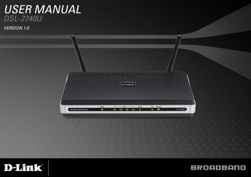
Product Overview<br />
• <strong>DSL</strong>-2760U Wireless A<strong>DSL</strong> Router<br />
• 2 Antennas<br />
• Power Adapter<br />
• CD-ROM with Installation Wizard, <strong>User</strong> <strong>Manual</strong>, and Special Offers<br />
• One twisted-pair telephone cable used for A<strong>DSL</strong> connection<br />
• One straight-through Ethernet cable<br />
• One Quick Installation Guide<br />
Note: Using a power supply with a different voltage rating than the one included<br />
with the <strong>DSL</strong>-2760U will cause damage and void the warranty for this product.<br />
• A<strong>DSL</strong> Internet service<br />
• Computer with:<br />
• 200MHz Processor<br />
• 64MB Memory<br />
• CD-ROM Drive<br />
• Ethernet Adapter with TCP/IP Protocol Installed<br />
• Windows 2000/XP/Vista<br />
• Internet Explorer v6 or later, FireFox v1.5<br />
• D-<strong>Link</strong> Click'n Connect Utility<br />
• Computer with Windows 2000/XP/Vista<br />
Package <strong>Content</strong>s<br />
System Requirements<br />
D-<strong>Link</strong> <strong>DSL</strong>-<strong>2740U</strong> <strong>User</strong> <strong>Manual</strong> 3
Section 1 - Product Overview<br />
11<br />
Introduction<br />
HIGH-SPEED A<strong>DSL</strong>2/2+ INTERNET CONNECTION<br />
Latest A<strong>DSL</strong>2/2+ standards provide Internet transmission <strong>of</strong> up to 24Mbps downstream, 1Mbps upstream.<br />
HIGH-PERFORMANCE WIRELESS<br />
Embedded latest draft 802.11n technology for high-speed wireless connection, complete compatibility with 802.11b/g wireless devices<br />
TOTAL SECURITY & QoS<br />
Firewall protection from Internet attacks, user access control, WPA/WPA2 wireless security and priority queues for smooth VoIP traffic/streaming multimedia<br />
ULTIMATE INTERNET CONNECTION<br />
The <strong>DSL</strong>-2760U RangeBooster N A<strong>DSL</strong>2+ router is a versatile, high-performance remote router for home and the small <strong>of</strong>fice. With integrated A<strong>DSL</strong>2/2+<br />
supporting up to 24Mbps download speed, firewall protection, Quality <strong>of</strong> Service (QoS), draft 802.11n wireless LAN and 4 Ethernet switch ports, this router<br />
provides all the functions that a home or small <strong>of</strong>fice needs to establish a secure and high-speed remote link to the outside world.<br />
ULTIMATE WIRELESS CONNECTION WITH MAXIMUM SECURITY<br />
Powered by RangeBooster N technology, this router provides wireless speeds that are up to 4 times faster than 802.11g 1. Maximize wireless performance by<br />
connecting this router to computers equipped with RangeBooster N wireless interfaces and stay connected from virtually anywhere at home and in the <strong>of</strong>fice. The<br />
router can also be used with 802.11g and 802.11b wireless networks to enable significantly improved reception. It supports WPA/WPA2 and WEP for flexible user<br />
access security and data encryption methods.<br />
FIREWALL PROTECTION & QoS<br />
Security features prevents unauthorized access to the home and <strong>of</strong>fice network, be it from the wireless devices or from the Internet. The router provides firewall<br />
security using Stateful Packet Inspection (SPI) and hacker attack logging for Denial <strong>of</strong> Service (DoS) attack protection. SPI inspects the contents <strong>of</strong> all incoming<br />
packet headers before deciding what packets are allowed to pass through. Router access control is provided with packet filtering based on port and<br />
source/destination MAC/IP addresses. For Quality <strong>of</strong> Service (QoS), the router supports multiple priority queues to enable a group <strong>of</strong> home or <strong>of</strong>fice users to<br />
experience the benefit <strong>of</strong> smooth network connection <strong>of</strong> inbound and outbound data without concern <strong>of</strong> traffic congestion. This QoS support allows users to enjoy<br />
high A<strong>DSL</strong> transmission for applications such as VoIP and streaming multimedia over the Internet.<br />
*Maximum wireless signal rate derived from IEEE standard 802.11g and draft 802.11n specifications. 802.11n speeds obtainable when operating among RangeBooster N products. Actual data<br />
throughput will vary. Network conditions and environmental factors, including volume <strong>of</strong> network traffic, building materials and construction, and network overhead, lower actual data throughput rate.<br />
Environmental factors will adversely affect wireless signal range.<br />
D-<strong>Link</strong> <strong>DSL</strong>-<strong>2740U</strong> <strong>User</strong> <strong>Manual</strong> 4
Section 1 - Product Overview<br />
Features<br />
• Faster Wireless Networking - The <strong>DSL</strong>-2760U provides up to 270Mbps* wireless connection with other 802.11n wireless clients. This<br />
capability allows users to participate in real-time activities online, such as video streaming, online gaming, and real-time audio.<br />
• Compatible with 802.11b and 802.11g Devices - The <strong>DSL</strong>-2760U is still fully compatible with the IEEE 802.11b and g standards, so it can<br />
connect with existing 802.11b and g PCI, USB and Cardbus adapters.<br />
• DHCP Support - Dynamic Host Configuration Protocol automatically and dynamically assigns all LAN IP settings to each host on your<br />
network. This eliminates the need to reconfigure every host whenever changes in network topology occur.<br />
• Network Address Translation (NAT) - For small <strong>of</strong>fice environments, the <strong>DSL</strong>-2760U allows multiple users on the LAN to access the<br />
Internet concurrently through a single Internet account. This provides Internet access to everyone in the <strong>of</strong>fice for the price <strong>of</strong> a single user.<br />
NAT improves network security in effect by hiding the private network behind one global and visible IP address. NAT address mapping can<br />
also be used to link two IP domains via a LAN-to-LAN connection.<br />
• Precise ATM Traffic Shaping - Traffic shaping is a method <strong>of</strong> controlling the flow rate <strong>of</strong> ATM data cells. This function helps to establish the<br />
Quality <strong>of</strong> Service for ATM data transfer.<br />
• High Performance - Very high rates <strong>of</strong> data transfer are possible with the Router. Up to 24Mbps downstream bit rate using the G.dmt<br />
standard. (For A<strong>DSL</strong>2+)<br />
• Full Network Management - The <strong>DSL</strong>-2760U incorporates SNMP (Simple Network Management Protocol) support for web-based<br />
management and text-based network management via Telnet connection.<br />
• Easy Installation - The <strong>DSL</strong>-2760U uses a web-based graphical user interface program for convenient management access and easy set<br />
up. Any common web browser s<strong>of</strong>tware can be used to manage the Router.<br />
*Maximum wireless signal rate derived from IEEE standard 802.11g and draft 802.11n specifications. 802.11n speeds obtainable when operating among RangeBooster N products. Actual data<br />
throughput will vary. Network conditions and environmental factors, including volume <strong>of</strong> network traffic, building materials and construction, and network overhead, lower actual data throughput rate.<br />
Environmental factors will adversely affect wireless signal range.<br />
D-<strong>Link</strong> <strong>DSL</strong>-<strong>2740U</strong> <strong>User</strong> <strong>Manual</strong> 5
Section 1 - Product Overview<br />
A<strong>DSL</strong> port<br />
Use the A<strong>DSL</strong> cable to connect<br />
to the your telephone line (RJ-11<br />
port)<br />
Ethernet ports<br />
Use the Ethernet ports to connect<br />
the Router to your Ethernet LAN<br />
or Ethernet devices<br />
Hardware Overview<br />
Connections<br />
Wireless On/Off switch<br />
For wireless operation on or<br />
<strong>of</strong>f.<br />
Power insert<br />
Use the adapter shipped with the<br />
Router to connect to power<br />
source<br />
Reset button<br />
To manually reset, depress<br />
button with the power on for<br />
between ten and fifteen seconds<br />
Power button<br />
Push in to power-on the Router.<br />
Push again to power-<strong>of</strong>f the<br />
Router<br />
D-<strong>Link</strong> <strong>DSL</strong>-<strong>2740U</strong> <strong>User</strong> <strong>Manual</strong> 6
Section 1 - Product Overview<br />
Power<br />
Steady green light<br />
indicates the unit is<br />
powered on. When the<br />
device is powered <strong>of</strong>f this<br />
remains dark.<br />
Hardware Overview<br />
LEDs<br />
WLAN<br />
Steady green light<br />
indicates a wireless<br />
connection. A blinking<br />
green light indicates<br />
activity on the WLAN<br />
LAN<br />
A solid green light indicates a valid link on startup. These<br />
lights blink when there is activity currently passing<br />
through the Ethernet port.<br />
<strong>DSL</strong><br />
Steady green light indicates a<br />
valid A<strong>DSL</strong> connection. This will<br />
light after the A<strong>DSL</strong> negotiation<br />
process has been settled. A<br />
blinking green light indicates<br />
activity on the WAN (A<strong>DSL</strong>)<br />
interface.<br />
Internet<br />
Steady green light indicates a successful Internet connection.<br />
Steady red light indicates failed Internet connection. Dark if no<br />
WAN protocol is configured.<br />
D-<strong>Link</strong> <strong>DSL</strong>-<strong>2740U</strong> <strong>User</strong> <strong>Manual</strong> 7
Section 2 - Installation<br />
Installation<br />
This section will walk you through the installation process. Placement <strong>of</strong> the router is very important. Do not place the router in an enclosed area<br />
such as a closet, cabinet, or in the attic or garage.<br />
Before you Begin<br />
Please read and make sure you understand all the prerequisites for proper installation <strong>of</strong> your new Router. Have all the necessary information and<br />
equipment on hand before beginning the installation.<br />
D-<strong>Link</strong> <strong>DSL</strong>-<strong>2740U</strong> <strong>User</strong> <strong>Manual</strong> 8
Section 2 - Installation<br />
Installation Notes<br />
In order to establish a connection to the Internet it will be necessary to provide information to the Router that will be stored in its memory. For some<br />
users, only their account information (<strong>User</strong>name and Password) is required. For others, various parameters that control and define the Internet<br />
connection will be required. You can print out the two pages below and use the tables to list this information. This way you have a hard copy <strong>of</strong> all<br />
the information needed to setup the Router. If it is necessary to reconfigure the device, all the necessary information can be easily accessed. Be<br />
sure to keep this information safe and private.<br />
Low Pass Filters<br />
Since A<strong>DSL</strong> and telephone services share the same copper wiring to carry their respective signals, a filtering mechanism may be necessary to<br />
avoid mutual interference. A low pass filter device can be installed for each telephone that shares the line with the A<strong>DSL</strong> line. These filters are easy<br />
to install passive devices that connect to the A<strong>DSL</strong> device and/or telephone using standard telephone cable. Ask your service provider for more<br />
information about the use <strong>of</strong> low pass filters with your installation.<br />
Operating Systems<br />
The <strong>DSL</strong>-2760U uses an HTML-based web interface for setup and management. The web configuration manager may be accessed using any<br />
operating system capable <strong>of</strong> running web browser s<strong>of</strong>tware, including Windows 98 SE, Windows ME, Windows 2000, and Windows XP/Vista.<br />
Web Browser<br />
Any common web browser can be used to configure the Router using the web configuration management s<strong>of</strong>tware. The program is designed to<br />
work best with more recently released browsers such as Opera, Micros<strong>of</strong>t Internet Explorer® version 6.0, Netscape Navigator® version 6.2.3, or<br />
later versions. The web browser must have JavaScript enabled. JavaScript is enabled by default on many browsers. Make sure JavaScript has not<br />
been disabled by other s<strong>of</strong>tware (such as virus protection or web user security packages) that may be running on your computer.<br />
Ethernet Port (NIC Adapter)<br />
Any computer that uses the Router must be able to connect to it through the Ethernet port on the Router. This connection is an Ethernet connection<br />
and therefore requires that your computer be equipped with an Ethernet port as well. Most notebook computers are now sold with an Ethernet port<br />
already installed. Likewise, most fully assembled desktop computers come with an Ethernet NIC adapter as standard equipment. If your computer<br />
does not have an Ethernet port, you must install an Ethernet NIC adapter before you can use the Router. If you must install an adapter, follow the<br />
installation instructions that come with the Ethernet NIC adapter.<br />
D-<strong>Link</strong> <strong>DSL</strong>-<strong>2740U</strong> <strong>User</strong> <strong>Manual</strong> 9
Section 2 - Installation<br />
802.11 Wireless LAN Configuration<br />
All the 802.11 wireless LAN settings may be configured on a single page using the web-based manager. For basic wireless communication you<br />
need to decide what channel to use and what SSID to assign. These two settings must be the same for any wireless workstations or other wireless<br />
access point that communicate with the <strong>DSL</strong>-2760U through the wireless interface.<br />
Security for wireless communication can be accomplished in a number <strong>of</strong> ways. The <strong>DSL</strong>-2760U supports WPA (Wi-Fi Protected Access), WPA2,<br />
and mixed WPA/WPA2. Wireless access can also be controlled by selecting MAC addresses that are allowed to associate with the device. Please<br />
read the section on Wireless Configuration.<br />
Additional S<strong>of</strong>tware<br />
It may be necessary to install s<strong>of</strong>tware on your computer that enables the computer to access the Internet. Additional s<strong>of</strong>tware must be installed if<br />
you are using the device a simple bridge. For a bridged connection, the information needed to make and maintain the Internet connection is stored<br />
on another computer or gateway device, not in the Router itself.<br />
If your A<strong>DSL</strong> service is delivered through a PPPoE or PPPoA connection, the information needed to establish and maintain the Internet connection<br />
can be stored in the Router. In this case, it is not necessary to install s<strong>of</strong>tware on your computer. It may however be necessary to change some<br />
settings in the device, including account information used to identify and verify the connection.<br />
All connections to the Internet require a unique global IP address. For bridged connections, the global IP settings must reside in a TCP/IP enabled<br />
device on the LAN side <strong>of</strong> the bridge, such as a PC, a server, a gateway device such as a router or similar firewall hardware. The IP address can be<br />
assigned in a number <strong>of</strong> ways. Your network service provider will give you instructions about any additional connection s<strong>of</strong>tware or NIC<br />
configuration that may be required.<br />
D-<strong>Link</strong> <strong>DSL</strong>-<strong>2740U</strong> <strong>User</strong> <strong>Manual</strong> 10
Section 2 - Installation<br />
Information you will need from your A<strong>DSL</strong> service<br />
provider<br />
<strong>User</strong>name<br />
This is the <strong>User</strong>name used to log on to your A<strong>DSL</strong> service provider’s network. It is commonly in the form user@isp.co.uk. Your A<strong>DSL</strong> service<br />
provider uses this to identify your account.<br />
Password<br />
This is the Password used, in conjunction with the <strong>User</strong>name above, to log on to your A<strong>DSL</strong> service provider’s network. This is used to verify the<br />
identity <strong>of</strong> your account.<br />
WAN Setting / Connection Type<br />
These settings describe the method your A<strong>DSL</strong> service provider uses to transport data between the Internet and your computer. Most users will use<br />
the default settings. You may need to specify one <strong>of</strong> the following WAN Setting and Connection Type configurations (Connection Type settings listed<br />
in parenthesis):<br />
• PPPoE/PPoA (PPPoE LLC, PPPoA LLC or PPPoA VC-Mux)<br />
• Bridge Mode (1483 Bridged IP LLC or 1483 Bridged IP VC Mux)<br />
• IPoA/MER (Static IP Address) (Bridged IP LLC, 1483 Bridged IP VC Mux, 1483 Routed IP LLC, 1483 Routed IP VC-Mux or IPoA)<br />
• MER (Dynamic IP Address) (1483 Bridged IP LLC or 1483 Bridged IP VC-Mux)<br />
Modulation Type<br />
A<strong>DSL</strong> uses various standardized modulation techniques to transmit data over the allotted signal frequencies. Some users may need to change the<br />
type <strong>of</strong> modulation used for their service. The default <strong>DSL</strong> modulation (A<strong>DSL</strong>2+ Multi-Mode) used for the Router automatically detects all types <strong>of</strong><br />
A<strong>DSL</strong>, A<strong>DSL</strong>2, and A<strong>DSL</strong>2+ modulation. However, if you are instructed to specify the modulation type used for the Router, you may choose among<br />
the numerous options available on the Modulation Type drop-down menu on the A<strong>DSL</strong> Configuration window (Advanced > A<strong>DSL</strong>)<br />
Security Protocol<br />
This is the method your A<strong>DSL</strong> service provider will use to verify your <strong>User</strong>name and Password when you log on to their network. Your Router<br />
supports the PAP and CHAP protocols.<br />
D-<strong>Link</strong> <strong>DSL</strong>-<strong>2740U</strong> <strong>User</strong> <strong>Manual</strong> 11
Section 2 - Installation<br />
VPI<br />
Most users will not be required to change this setting. The Virtual Path Identifier (VPI) is used in conjunction with the Virtual Channel Identifier (VCI)<br />
to identify the data path between your A<strong>DSL</strong> service provider’s network and your computer. If you are setting up the Router for multiple virtual<br />
connections, you will need to configure the VPI and VCI as instructed by your A<strong>DSL</strong> service provider for the additional connections. This setting can<br />
be changed in the WAN Settings window <strong>of</strong> the web management interface.<br />
VCI<br />
Most users will not be required to change this setting. The Virtual Channel Identifier (VCI) used in conjunction with the VPI to identify the data path<br />
between your A<strong>DSL</strong> service provider’s network and your computer. If you are setting up the Router for multiple virtual connections, you will need to<br />
configure the VPI and VCI as instructed by your A<strong>DSL</strong> service provider for the additional connections. This setting can be changed in the WAN<br />
Settings window <strong>of</strong> the web management interface.<br />
D-<strong>Link</strong> <strong>DSL</strong>-<strong>2740U</strong> <strong>User</strong> <strong>Manual</strong> 12
Section 2 - Installation<br />
Information you will need about <strong>DSL</strong>-2760U<br />
<strong>User</strong>name<br />
This is the <strong>User</strong>name needed access the Router’s management interface. When you attempt to connect to the device through a web browser you<br />
will be prompted to enter this <strong>User</strong>name. The default <strong>User</strong>name for the Router is “admin.” The user cannot change this.<br />
Password<br />
This is the Password you will be prompted to enter when you access the Router’s management interface. The default Password is “admin.” The<br />
user may change this.<br />
LAN IP addresses for the <strong>DSL</strong>-2760U<br />
This is the IP address you will enter into the Address field <strong>of</strong> your web browser to access the Router’s configuration graphical user interface (GUI)<br />
using a web browser. The default IP address is 192.168.1.1. This may be changed to suit any IP address scheme the user desires. This address will<br />
be the base IP address used for DHCP service on the LAN when DHCP is enabled.<br />
LAN Subnet Mask for the <strong>DSL</strong>-2760U<br />
This is the subnet mask used by the <strong>DSL</strong>-2760U, and will be used throughout your LAN. The default subnet mask is 255.255.255.0. This can be<br />
changed later.<br />
D-<strong>Link</strong> <strong>DSL</strong>-<strong>2740U</strong> <strong>User</strong> <strong>Manual</strong> 13
Section 2 - Installation<br />
Information you will need about your LAN or computer:<br />
Ethernet NIC<br />
If your computer has an Ethernet NIC, you can connect the <strong>DSL</strong>-2760U to this Ethernet port using an Ethernet cable. You can also use the Ethernet<br />
ports on the <strong>DSL</strong>-2760U to connect to other computer or Ethernet devices.<br />
DHCP Client status<br />
Your <strong>DSL</strong>-2760U A<strong>DSL</strong> Router is configured, by default, to be a DHCP server. This means that it can assign an IP address, subnet mask, and a<br />
default gateway address to computers on your LAN. The default range <strong>of</strong> IP addresses the <strong>DSL</strong>-2760U will assign are from 192.168.1.2 to<br />
192.168.1.254. Your computer (or computers) needs to be configured to Obtain an IP address automatically (that is, they need to be configured as<br />
DHCP clients.)<br />
It is recommended that your collect and record this information here, or in some other secure place, in case you have to re-configure your A<strong>DSL</strong><br />
connection in the future.<br />
Once you have the above information, you are ready to setup and configure your <strong>DSL</strong>-2760U Wireless A<strong>DSL</strong> Router.<br />
D-<strong>Link</strong> <strong>DSL</strong>-<strong>2740U</strong> <strong>User</strong> <strong>Manual</strong> 14
Section 2 - Installation<br />
Wireless Installation Considerations<br />
<strong>DSL</strong>-2760U lets you access your network using a wireless connection from virtually anywhere within the operating range <strong>of</strong> your wireless network.<br />
Keep in mind, however, that the number, thickness and location <strong>of</strong> walls, ceilings, or other objects that the wireless signals must pass through, may<br />
limit the range. Typical ranges vary depending on the types <strong>of</strong> materials and background RF (radio frequency) noise in your home or business. The<br />
key to maximizing wireless range is to follow these basic guidelines:<br />
1. Keep the number <strong>of</strong> walls and ceilings between the D-<strong>Link</strong> router and other network devices to a minimum - each wall or ceiling can reduce your<br />
adapter’s range from 3-90 feet (1-30 meters.) Position your devices so that the number <strong>of</strong> walls or ceilings is minimized.<br />
2. Be aware <strong>of</strong> the direct line between network devices. A wall that is 1.5 feet thick (.5 meters), at a 45-degree angle appears to be almost 3 feet (1<br />
meter) thick. At a 2-degree angle it looks over 42 feet (14 meters) thick! Position devices so that the signal will travel straight through a wall or<br />
ceiling (instead <strong>of</strong> at an angle) for better reception.<br />
3. Building Materials make a difference. A solid metal door or aluminum studs may have a negative effect on range. Try to position access points,<br />
wireless routers, and computers so that the signal passes through drywall or open doorways. Materials and objects such as glass, steel, metal,<br />
walls with insulation, water (fish tanks), mirrors, file cabinets, brick, and concrete will degrade your wireless signal.<br />
4. Keep your product away (at least 3-6 feet or 1-2 meters) from electrical devices or appliances that generate RF noise.<br />
5. If you are using 2.4GHz cordless phones or X-10 (wireless products such as ceiling fans, lights, and home security systems), your wireless<br />
connection may degrade dramatically or drop completely. Make sure your 2.4GHz phone base is as far away from your wireless devices as<br />
possible. The base transmits a signal even if the phone in not in use.<br />
D-<strong>Link</strong> <strong>DSL</strong>-<strong>2740U</strong> <strong>User</strong> <strong>Manual</strong> 15
Section 2 - Installation<br />
Device Installation<br />
The <strong>DSL</strong>-2760U Wireless A<strong>DSL</strong> Router maintains three separate interfaces, an Ethernet LAN, a wireless LAN and an A<strong>DSL</strong> Internet (WAN)<br />
connection. Carefully consider the Router’s location suitable for connectivity for your Ethernet and wireless devices. You must have a functioning<br />
broadband connection via a bridge device such as a Cable or A<strong>DSL</strong> modem in order to use the Router’s WAN function.<br />
Place the Router in a location where it can be connected to the various devices as well as to a power source. The Router should not be located<br />
where it will be exposed to moisture, direct sunlight or excessive heat. Make sure the cables and power cord are placed safely out <strong>of</strong> the way so<br />
they do not create a tripping hazard. As with any electrical appliance, observe common sense safety procedures.<br />
The Router can be placed on a shelf, desktop, or other stable platform. If possible, you should be able to see the LED indicators on the front if you<br />
need to view them for troubleshooting.<br />
Power on Router<br />
The Router must be used with the power adapter included with the device.<br />
1. Insert the AC Power Adapter cord into the power receptacle located on the rear panel <strong>of</strong> the Router and plug the adapter into a suitable nearby<br />
power source.<br />
2. Push down the Power button, and you should see the Power LED indicator light up and remain lit.<br />
3. If the Ethernet port is connected to a working device, check the Ethernet <strong>Link</strong>/Act LED indicators to make sure the connection is valid. The<br />
Router will attempt to establish the A<strong>DSL</strong> connection, if the A<strong>DSL</strong> line is connected and the Router is properly configured this should light up<br />
after several seconds. If this is the first time installing the device, some settings may need to be changed before the Router can establish a<br />
connection.<br />
D-<strong>Link</strong> <strong>DSL</strong>-<strong>2740U</strong> <strong>User</strong> <strong>Manual</strong> 16
Section 2 - Installation<br />
Factory Reset Button<br />
The Router may be reset to the original factory default settings by using a ballpoint or paperclip to gently push down the reset button in the following<br />
sequence:<br />
1. Press and hold the reset button while the device is powered <strong>of</strong>f.<br />
2. Turn on the power.<br />
3. Wait for 10~15 seconds and then release the reset button.<br />
Remember that this will wipe out any settings stored in flash memory including user account information and LAN IP settings. The device settings<br />
will be restored to the factory default IP address 192.168.1.1 and the subnet mask is 255.255.255.0, the default management <strong>User</strong>name is “admin”<br />
and the default Password is “admin.”<br />
Network Connections<br />
Connect A<strong>DSL</strong> Line<br />
Use the A<strong>DSL</strong> cable included with the Router to connect it to a telephone wall socket or receptacle. Plug one end <strong>of</strong> the cable into the A<strong>DSL</strong> port<br />
(RJ-11 receptacle) on the rear panel <strong>of</strong> the Router and insert the other end into the RJ-11 wall socket. If you are using a low pass filter device, follow<br />
the instructions included with the device or given to you by your service provider. The A<strong>DSL</strong> connection represents the WAN interface, the<br />
connection to the Internet. It is the physical link to the service provider’s network backbone and ultimately to the Internet.<br />
Connect Router to Ethernet<br />
The Router may be connected to a single computer or Ethernet device through the 10BASE-TX Ethernet port on the rear panel. Any connection to<br />
an Ethernet concentrating device such as a switch or hub must operate at a speed <strong>of</strong> 10/100 Mbps only. When connecting the Router to any<br />
Ethernet device that is capable <strong>of</strong> operating at speeds higher than 10Mbps, be sure that the device has auto-negotiation (NWay) enabled for the<br />
connecting port. Use standard twisted-pair cable with RJ-45 connectors. The RJ-45 port on the Router is a crossed port (MDI-X). Follow standard<br />
Ethernet guidelines when deciding what type <strong>of</strong> cable to use to make this connection. When connecting the Router directly to a PC or server use a<br />
normal straight-through cable. You should use a crossed cable when connecting the Router to a normal (MDI-X) port on a switch or hub. Use a<br />
normal straight-through cable when connecting it to an uplink (MDI-II) port on a hub or switch. The rules governing Ethernet cable lengths apply to<br />
the LAN to Router connection. Be sure that the cable connecting the LAN to the Router does not exceed 100 meters.<br />
D-<strong>Link</strong> <strong>DSL</strong>-<strong>2740U</strong> <strong>User</strong> <strong>Manual</strong> 17
Section 2 - Installation<br />
Hub or Switch to Router Connection<br />
Connect the Router to an uplink port (MDI-II) on an Ethernet hub or switch<br />
with a straight-through cable as shown in this diagram. If you wish to reserve<br />
the uplink port on the switch or hub for another device, connect to any on the<br />
other MDI-X ports (1x, 2x, etc.) with a crossed cable.<br />
Computer to Router Connection<br />
You can connect the Router directly to a 10/100BASE-TX Ethernet adapter<br />
card (NIC) installed on a PC using the Ethernet cable provided as shown in<br />
this diagram.<br />
D-<strong>Link</strong> <strong>DSL</strong>-<strong>2740U</strong> <strong>User</strong> <strong>Manual</strong> 18
Section 3 – Configuration<br />
Configuration<br />
This section will show you how to configure your new D-<strong>Link</strong> wireless router using the web-based configuration utility.<br />
Web-based Configuration Utility<br />
Connect to the Router<br />
To configure the WAN connection used by the Router it is first necessary to communicate with the Router through its management interface, which<br />
is HTML-based and can be accessed using a web browser. The easiest way to make sure your computer has the correct IP settings is to configure<br />
it to use the DHCP server in the Router. The next section describes how to change the IP configuration for a computer running a Windows operating<br />
system to be a DHCP client.<br />
To access the configuration utility, open a web-browser such as Internet<br />
Explorer and enter the IP address <strong>of</strong> the router (192.168.1.1).<br />
Type “admin” in the Password field. If you get a Page Cannot be<br />
Displayed error, please refer to the Troubleshooting section for<br />
assistance.<br />
D-<strong>Link</strong> <strong>DSL</strong>-<strong>2740U</strong> <strong>User</strong> <strong>Manual</strong> 19
Section 3 – Configuration<br />
SETUP<br />
This chapter is concerned with using your computer to configure the WAN connection. The following chapter describes the various windows used to<br />
configure and monitor the Router including how to change IP settings and DHCP server setup.<br />
WIZARD<br />
A<strong>DSL</strong> SETUP<br />
Click on the Setup Wizard button to launch the Setup Wizard.<br />
WELCOME TO D-LINK SETUP WIZARD<br />
There are three steps to configuring your router. Click on the Next to<br />
continue.<br />
D-<strong>Link</strong> <strong>DSL</strong>-<strong>2740U</strong> <strong>User</strong> <strong>Manual</strong> 20
Section 3 – Configuration<br />
STEP 1: CHANGE YOUR <strong>DSL</strong>-2760U PASSWORD<br />
The default password is "admin", in order to secure your network, please<br />
modify the password. Note: Confirm Password must be same as "New<br />
Password". Of course, you can click on the Skip to ignore the step.<br />
STEP 2: SELECT INTERNET CONNECTION TYPE<br />
Please select your Country and ISP, the VPI and VCI information Will display<br />
Automatically. Of course, you can modify the information.<br />
If, you can not find the country and ISP in the list below; you can select<br />
"Others", and then input the "VPI" and "VCI” and Connection Type.<br />
Click on the Next button to go to the next Setup Wizard window.<br />
D-<strong>Link</strong> <strong>DSL</strong>-<strong>2740U</strong> <strong>User</strong> <strong>Manual</strong> 21
Section 3 – Configuration<br />
STEP 2: SELECT INTERNET CONNECTION TYPE<br />
Select the appropriate Internet connection type based on the information<br />
provided to you by your ISP.<br />
Please enter the VPI/VCI numbers if provided by the ISP.<br />
Click on the Next button to go to the next Setup Wizard window.<br />
Using the Setup Wizard - For PPPoE/PPPoA connection<br />
Type in the <strong>User</strong>name and Password.<br />
Click on the Next button to go to the next Setup Wizard window.<br />
D-<strong>Link</strong> <strong>DSL</strong>-<strong>2740U</strong> <strong>User</strong> <strong>Manual</strong> 22
Section 3 – Configuration<br />
Using the Setup Wizard - For Dynamic IP Address connection<br />
Please enter the appropriate information below as provided by your ISP.<br />
Maybe, you have to input your PC MAC address if ISP requires, and you can<br />
click on the Copy Your PC’s MAC Address button to copy it.<br />
Click on the Next button to go to the next Setup Wizard window.<br />
Using the Setup Wizard - For Static IP Address connection<br />
Please enter the appropriate information below as provided by your ISP.<br />
Please input the correct IP address, Subnet Mask, Default Gateway and<br />
DNS information.<br />
Note: Should you select to leave default Gateway and DNS information blank,<br />
they should be automatically generated.<br />
Click on the Next button to go to the next Setup Wizard window.<br />
D-<strong>Link</strong> <strong>DSL</strong>-<strong>2740U</strong> <strong>User</strong> <strong>Manual</strong> 23
Section 3 – Configuration<br />
STEP 3: RESTART<br />
Click Back to review or modify settings. Click on Apply to apply current<br />
settings. If your Internet connection does not work after the wizard<br />
configuration, you can try the Setup Wizard again with alternative settings or<br />
use <strong>Manual</strong> Setup instead provided you have your Internet connection details<br />
as provided to you by your ISP.<br />
D-<strong>Link</strong> <strong>DSL</strong>-<strong>2740U</strong> <strong>User</strong> <strong>Manual</strong> 24
Section 3 – Configuration<br />
A<strong>DSL</strong> SETUP<br />
To access the A<strong>DSL</strong> SETUP (WAN) settings window, click on the Internet Setup button in the SETUP directory and select the <strong>Manual</strong> Setup to<br />
configure the MANUAL A<strong>DSL</strong> interface in this page:<br />
WAN INTERFACE SETUP<br />
There are two ways to setup your wan interfaces. You can use the ATM<br />
Setup wizard or you can use ETH setup wizard.<br />
Click Setup button in the A<strong>DSL</strong> INTERFACE section if you want to use<br />
ATM to configure your wan interface.<br />
Please refer to page 26 ATM Interface - A<strong>DSL</strong> SETUP for the next step.<br />
Click Setup button in the ETHERNET WAN INTERFACE section if you<br />
want to use ETH to configure your wan interface.<br />
Please refer to page 28 ETH Interface – ETH WAN Setup for the next step.<br />
D-<strong>Link</strong> <strong>DSL</strong>-<strong>2740U</strong> <strong>User</strong> <strong>Manual</strong> 25
Section 3 – Configuration<br />
ATM Interface - A<strong>DSL</strong> SETUP<br />
Check the <strong>Manual</strong> Setup check box and configure the below messages<br />
with the required information as the same as in WIZARD.<br />
Click on the Apply button to apply and save your settings.<br />
Click on the Connect button to connect the router to the Internet with the<br />
WAN interface.<br />
D-<strong>Link</strong> <strong>DSL</strong>-<strong>2740U</strong> <strong>User</strong> <strong>Manual</strong> 26
Section 3 – Configuration<br />
When the router is connected to the Internet, the Internet Online graphical<br />
icon will be in color. If it is in dark and you are having problems browsing<br />
web pages, then there may be a problem with your internet settings and you<br />
will need to revert to step 2.<br />
Click on the Disconnect button to disconnect the router to the Internet and<br />
the icon will be dark.<br />
D-<strong>Link</strong> <strong>DSL</strong>-<strong>2740U</strong> <strong>User</strong> <strong>Manual</strong> 27
Section 3 – Configuration<br />
ETH Interface – ETH WAN Setup<br />
This screen allows you to configure an ETH port to be WAN port.<br />
Select the port from drop down menu and configure the below messages<br />
with the required information as the same as in WIZARD.<br />
Click on the Apply button to apply and save your settings.<br />
D-<strong>Link</strong> <strong>DSL</strong>-<strong>2740U</strong> <strong>User</strong> <strong>Manual</strong> 28
Section 3 – Configuration<br />
WIRELESS<br />
Use this section to configure the wireless settings for your D-<strong>Link</strong> router. Please note that changes made in this section will also need to be<br />
duplicated onto your wireless clients and PC.<br />
To access the WIRELESS (WLAN) settings window, click on the Wireless Setup button in the SETUP directory.<br />
Wireless Network Setting<br />
Click on the Wireless Connection Setup Wizard button to setup the<br />
wireless connection in an easy way. It will use Web-based Wizard to<br />
assist you in connecting to your new D-<strong>Link</strong> Systems Wireless Router.<br />
Note: Before launching the wizard, please make sure you have followed<br />
all steps outlined in the Quick Installation Guide included in the package.<br />
Click on the Add Wireless Device with WPS button. This wizard is<br />
designed to assist you in connecting your wireless device to your router<br />
with WPS. It will guide you through step-by-step instructions on how to<br />
get your wireless device connected.<br />
If you would like to configure the Internet settings <strong>of</strong> your new D-<strong>Link</strong><br />
Router manually, then click on the <strong>Manual</strong> Wireless Connection Setup<br />
button.<br />
D-<strong>Link</strong> <strong>DSL</strong>-<strong>2740U</strong> <strong>User</strong> <strong>Manual</strong> 29
Section 3 – Configuration<br />
Wireless Connection Setup Wizard<br />
Network Name(SSID) identifies members <strong>of</strong> the Service Set. Accept<br />
the default name or change it to something else. If the default SSID is<br />
changed, all other devices on the wireless network must also use the<br />
same SSID.<br />
Select Automatically assign a network key or <strong>Manual</strong>ly assign a<br />
network key to prevent outsides from accessing your network, the<br />
router will automatically assign a security key (also called WEP or WPA<br />
key) to your network.<br />
Enable Use WPA encryption instead <strong>of</strong> WEP will help provide a more<br />
secure wireless network. WPA is stronger than WEP and all D-<strong>Link</strong><br />
wireless client adapters support WPA.<br />
Click Prev to go back to previous page.<br />
Click Next button to proceed the next page.<br />
Click Cancel button to return to the main menu <strong>of</strong> Wireless Setup page.<br />
Wireless Connection Setup Wizard (<strong>Manual</strong>ly assign a network key<br />
with WPA enabled)<br />
The WPA(Wi-Fi Protected Access)key must meet one <strong>of</strong> the following<br />
guidelines:<br />
- Between 8 and 63 characters(A longer WPA key is more secure than a<br />
short one)<br />
- Exactly 63 characters using 0-9 and A-F<br />
Click Prev to go back to previous page.<br />
Click Next button to proceed the next page.<br />
Click Cancel button to return to the main menu <strong>of</strong> Wireless Setup page.<br />
D-<strong>Link</strong> <strong>DSL</strong>-<strong>2740U</strong> <strong>User</strong> <strong>Manual</strong> 30
Section 3 – Configuration<br />
Wireless Connection Setup Wizard (<strong>Manual</strong>ly assign a network key<br />
with WEP)<br />
The WEP(or Wired Equivalent Privacy)key must meet one <strong>of</strong> the<br />
following guidelines:<br />
- Exactly 5 or 13 characters<br />
- Exactly 10 or 26 characters using 0-9 and A-F<br />
A longer WEP key is more secure than a short one.<br />
Click Prev to go back to previous page.<br />
Click Next button to proceed the next page.<br />
Click Cancel button to return to the main menu <strong>of</strong> Wireless Setup page.<br />
Wireless Connection Setup Wizard (Configuration Information)<br />
This screen shows the information for the SSID, Wireless Security Mode<br />
and the Network key.<br />
Click Prev to go back to previous page.<br />
Click Save button to save the current setting.<br />
Click Cancel button to return to the main menu <strong>of</strong> Wireless Setup page.<br />
D-<strong>Link</strong> <strong>DSL</strong>-<strong>2740U</strong> <strong>User</strong> <strong>Manual</strong> 31
Section 3 – Configuration<br />
Add Wireless Device with WPS<br />
The wizard shows the option to setup WPS by Auto or <strong>Manual</strong>.<br />
Auto -- Select this option if your wireless device supports WPS(Wi-Fi<br />
Protected Setup)<br />
<strong>Manual</strong> -- Select this option will display the current wireless settings for<br />
you to configure the wireless device manually.<br />
Click Next button to proceed the next page.<br />
Click Cancel button to return to the main menu <strong>of</strong> Wireless Setup page.<br />
Add Wireless Device with WPS (<strong>Manual</strong>ly)<br />
This screen shows the information for the SSID, Wireless Security Mode<br />
and the Network key and allow you to modify the current setting, if you<br />
select Auto in the previous page, you won’t see this page and please<br />
refer to next column.<br />
Click OK button to proceed the next page.<br />
D-<strong>Link</strong> <strong>DSL</strong>-<strong>2740U</strong> <strong>User</strong> <strong>Manual</strong> 32
Section 3 – Configuration<br />
Add Wireless Device with WPS (<strong>Manual</strong>ly)<br />
This page allows you to select PIN or PBC to use WPS method.<br />
PIN- Enter the PIN code from your wireless device and click the below<br />
Connect button to start the handshaking.<br />
PBC- Please press the push button on your wireless device and press<br />
the Connect button below within 120 seconds to start the handshaking.<br />
Click Prev to go back to previous page.<br />
Add Wireless Device with WPS (PIN)<br />
This page will count down the timer and please start WPS on the<br />
wireless device you are adding in time.<br />
Add Wireless Device with WPS (Push Button)<br />
This page will count down the timer and please start WPS in time by<br />
pressing down the Push button on your wireless device you are adding.<br />
D-<strong>Link</strong> <strong>DSL</strong>-<strong>2740U</strong> <strong>User</strong> <strong>Manual</strong> 33
Section 3 – Configuration<br />
<strong>Manual</strong> WIRELESS Connection Setup SETTINGS<br />
Click on the Enable Wireless check box to allow the router to operate in<br />
the wireless environment.<br />
The SSID identifies members <strong>of</strong> the Service Set. Accept the default<br />
name or change it to something else. If the default SSID is changed, all<br />
other devices on the wireless network must also use the same SSID.<br />
Enable Auto Channel Scan so that the router can select the best<br />
possible channel for your wireless network to operate on.<br />
The Wireless Channel can let you select the channel <strong>of</strong> your access<br />
point. Channel availability is different for different countries due to their<br />
regulation.<br />
Select 802.11 Mode to operate in b/g/n mode. Or select specified mode<br />
to use.<br />
Channel Width, Maximum rate for 20 MHz is 130 Mbps. Maximum rate<br />
for 40 MHz is 270 Mbps.<br />
Transmission Rate, suggest keeping the Best (automatic) selection.<br />
Click on the Hide Wireless Network check box to allow the router to<br />
stop broadcasting its SSID.<br />
D-<strong>Link</strong> <strong>DSL</strong>-<strong>2740U</strong> <strong>User</strong> <strong>Manual</strong> 34
Section 3 – Configuration<br />
WIRELESS SECURITY WIZARD<br />
Click on the Secure My Wireless Network button to enter the SECURE<br />
MY WIRELESS NETWORK window.<br />
Please follow refer to page 30~31.<br />
WIRELESS SECURITY MODE - WEP<br />
WEP (Wireless Encryption Protocol) encryption can be enabled for<br />
security and privacy. WEP encrypts the data portion <strong>of</strong> each frame<br />
transmitted from the wireless adapter using one <strong>of</strong> the predefined keys.<br />
The router <strong>of</strong>fers 64 or 128 bit encryption with four keys available.<br />
Select WEP Key Length from the drop-down menu. (128 bit is stronger<br />
than 64 bit)<br />
Enter the key into the WEP Key field 1~4. (Key length is outlined at the<br />
bottom <strong>of</strong> the window.)<br />
Specify the encryption key from the Default WEP Key drop-down menu.<br />
Select Authentication type from the drop-down menu. (Shared is<br />
better than Open)<br />
Click on the Apply Settings button to apply settings.<br />
D-<strong>Link</strong> <strong>DSL</strong>-<strong>2740U</strong> <strong>User</strong> <strong>Manual</strong> 35
Section 3 – Configuration<br />
WIRELESS SECURITY MODE – WPA-Personal<br />
WPA-PSK<br />
WPA-PSK configuration is similar to WEP. The key length is between 8<br />
to 63 ASCII codes.<br />
D-<strong>Link</strong> <strong>DSL</strong>-<strong>2740U</strong> <strong>User</strong> <strong>Manual</strong> 36
Section 3 – Configuration<br />
WIRELESS SECURITY MODE – WPA-Enterprise<br />
802.1x<br />
Some network-security experts now recommend that wireless networks<br />
use 802.1X security measures to overcome some weaknesses in<br />
standard WEP applications. A RADIUS server is used to authenticate all<br />
potential users. .<br />
Enter your RADIUS server data: IP Address, Port, and Shared Secret.<br />
Click on the Apply Settings button to apply settings.<br />
D-<strong>Link</strong> <strong>DSL</strong>-<strong>2740U</strong> <strong>User</strong> <strong>Manual</strong> 37
Section 3 – Configuration<br />
LAN SETUP<br />
You can configure the LAN IP address to suit your preference. Many users will find it convenient to use the default settings together with DHCP<br />
service to manage the IP settings for their private network. The IP address <strong>of</strong> the Router is the base address used for DHCP. In order to use the<br />
Router for DHCP on your LAN, the IP address pool used for DHCP must be compatible with the IP address <strong>of</strong> the Router. The IP addresses<br />
available in the DHCP IP address pool will change automatically if you change the IP address <strong>of</strong> the Router.<br />
To access the LAN SETUP setting window, click on the LAN Setup button in the SETUP directory.<br />
ROUTER SETTINGS<br />
To change the Router IP Address or Subnet Mask, type in the desired<br />
values.<br />
DHCP SERVER SETTINGS (OPTIONAL)<br />
The Enable DHCP Server is selected by default for the Router’s Ethernet<br />
LAN interface. DHCP service will supply IP settings to workstations<br />
configured to automatically obtain IP settings that are connected to the<br />
Router though the Ethernet port. When the Router is used for DHCP it<br />
becomes the default gateway for DHCP client connected to it. Keep in<br />
mind that if you change the IP address <strong>of</strong> the Router the range <strong>of</strong> IP<br />
addresses in the pool used for DHCP on the LAN will also be changed.<br />
The IP address pool can be up to 253 IP addresses.<br />
D-<strong>Link</strong> <strong>DSL</strong>-<strong>2740U</strong> <strong>User</strong> <strong>Manual</strong> 38
Section 3 – Configuration<br />
ADD DHCP RESERVATION (OPTIONAL)<br />
Select the DHCP Reservation Enable can let you reserve the IP<br />
Address for the designate PC with the configured MAC Address.<br />
The Computer Name can help you recognize the PC with the MAC<br />
Address, such as “Father’s Laptop”.<br />
Clicking on the Copy Your PC’s MAC Address button will help you get<br />
the MAC address from the PC you are using now browsing this web page.<br />
Click on the Apply button to save the settings<br />
DHCP RESERVATIONS LIST<br />
After saved the DHCP reservation, the DHCP RESERVATIONS LIST will<br />
list the configuration.<br />
The NUMBER OF DYNAMIC DHCP CLIENTS shows how many DHCP<br />
clients (PC or Laptop) connected to the router currently.<br />
Click on the Save Settings button to apply your settings.<br />
D-<strong>Link</strong> <strong>DSL</strong>-<strong>2740U</strong> <strong>User</strong> <strong>Manual</strong> 39
Section 3 – Configuration<br />
TIME<br />
The TIME configuration option allows you to configure, update, and maintain the correct time on the internal system clock. From this section you<br />
can set the time zone that you are in and set the NTP (Network Time Protocol) Server. Daylight Saving can also be configured to automatically<br />
adjust the time when needed.<br />
To access the TIME setting window, click on the Time and Date button in the SETUP directory<br />
TIME CONFIGURATION<br />
Check the Automatically synchronize with Internet<br />
time servers check box.<br />
Select specific time server to use from the NTP Server<br />
drop-down menu.<br />
Select your operating time zone from the Time Zone<br />
drop-down menu.<br />
Check the Enable Daylight Saving if needed and then<br />
select the proper Daylight Saving Offset drop-down<br />
menu. Configure the Daylight Saving Dates from<br />
start date to end.<br />
Set the Date and Time <strong>Manual</strong>ly<br />
You can either manually set the time for your router<br />
here, or you can click the "Copy Your Computer's Time<br />
Settings" button to copy the time from the computer you<br />
are using.<br />
Click on the Apply button to apply your settings.<br />
D-<strong>Link</strong> <strong>DSL</strong>-<strong>2740U</strong> <strong>User</strong> <strong>Manual</strong> 40
Section 3 – Configuration<br />
PARENTAL CONTROL<br />
The PARENTAL CONTROL provides two useful tools for restricting Internet access. Block Websites allows you to quickly create a list <strong>of</strong> all web<br />
sites that you wish to stop users from accessing. Time Restrictions allows you to control when clients or PCs connected to Router are allowed to<br />
access the Internet.<br />
To access the PARENTAL CONTROL setting window, click on the Parental Control button in the SETUP directory<br />
BLOCKED WEBSITES SCHEDULING<br />
Type the Website and select the<br />
corresponding time and days. Click on the<br />
Block Website button to add to your blocked<br />
websites scheduling configuration.<br />
Check the Unblock field in the tail <strong>of</strong> the row,<br />
and then click on the Unblock Website<br />
button. The checked items will be deleted<br />
from the table.<br />
INTERNET ACCESS TIME RESTRICTIONS<br />
Select days and time frame to allow/deny this<br />
rule.<br />
Click on the Save Settings button to apply<br />
settings.<br />
D-<strong>Link</strong> <strong>DSL</strong>-<strong>2740U</strong> <strong>User</strong> <strong>Manual</strong> 41
Section 3 – Configuration<br />
WIRELESS SCHEDULE<br />
The Wireless Schedule page allows you to create scheduling rules to be applied for your Wireless network.<br />
To access the WIRELESS SCHEDULE setting window, click on the Wireless Schedule button in the SETUP directory<br />
WIRELESS SCHEDULING<br />
Click on the Edit button to select the day and<br />
specify the time for your wireless network<br />
schedule.<br />
Click Save button to save and apply your<br />
settings.<br />
D-<strong>Link</strong> <strong>DSL</strong>-<strong>2740U</strong> <strong>User</strong> <strong>Manual</strong> 42
Section 3 – Configuration<br />
LOGOUT<br />
The LOGOUT page enables you to logout <strong>of</strong> your router and closes the browser.<br />
To access the LOGOUT setting window, click on the Logout button in the SETUP directory<br />
LOGOUT<br />
Click on the Logout button to logout <strong>of</strong> the<br />
router configuration settings and close the<br />
browser.<br />
D-<strong>Link</strong> <strong>DSL</strong>-<strong>2740U</strong> <strong>User</strong> <strong>Manual</strong> 43
Section 3 – Configuration<br />
ADVANCED<br />
This chapter include the more advanced features used for network management and security as well as administrative tools to manage the router,<br />
view status and other information used to examine performance and for troubleshooting.<br />
PORT FORWARDING<br />
Use the PORT FORWARDING window to open ports in your router and re-direct data through those ports to a single PC on your network<br />
(WAN-to-LAN traffic). The Port Forwarding function allows remote users to access services on your LAN such as FTP for file transfers or SMTP and<br />
POP3 for e-mail. The <strong>DSL</strong>-2760U will accept remote requests for these services at your Global IP Address, using the specified TCP or UDP<br />
protocol and port number, and then redirect these requests to the server on your LAN with the LAN IP address you specify. Remember that the<br />
specified Private IP Address must be within the useable range <strong>of</strong> the subnet occupied by the Router.<br />
To access the PORT FORWARDING settings window, click on the Port Forwarding button in the ADVANCED directory<br />
PORT FORWARDING RULES CONFIGURATION<br />
Select a name from the Application Name drop-down menu for a pre-configured<br />
application or type a name in the Name input box to define your own application.<br />
Select a name from the Computer Name drop-down menu or type an IP address<br />
in the IP address input box to appoint the PC to receive the forwarded packets.<br />
The External Port shows the ports opened for remote users in the WAN side <strong>of</strong><br />
the router. The TCP/UDP means the protocol type <strong>of</strong> the opened ports.<br />
The Internal Port shows the ports opened in the PC with the appointed IP<br />
Address. The TCP/UDP means the protocol type <strong>of</strong> the opened ports.<br />
Click on the Add/Apply button to apply settings.<br />
D-<strong>Link</strong> <strong>DSL</strong>-<strong>2740U</strong> <strong>User</strong> <strong>Manual</strong> 44
Section 3 – Configuration<br />
APPLICATION RULES<br />
Some applications require that specific ports in the Router's firewall be opened for access by the remote parties. Application rules dynamically open<br />
up the Firewall ports when an application on the LAN initiates a TCP/UDP connection to a remote party using the Trigger ports. The router allows<br />
the remote party from the WAN side to establish new connections back to the application on the LAN side using the Firewall ports. A maximum <strong>of</strong><br />
16 entries can be configured.<br />
To access the APPLICATION RULES setting window, click on the Application Rules button in the ADVANCED directory.<br />
APPLICATION RULES CONFIGURATION<br />
Select a name from the drop-down menu for<br />
pre-configured application or type a name in<br />
the Name input text box to define your own<br />
rules.<br />
Enter your Trigger and Firewall port(s), and<br />
select the Traffic Type.<br />
Click on the Add/Apply button to apply<br />
settings.<br />
D-<strong>Link</strong> <strong>DSL</strong>-<strong>2740U</strong> <strong>User</strong> <strong>Manual</strong> 45
Section 3 – Configuration<br />
QoS SETUP<br />
QoS or Quality <strong>of</strong> service allows your Router to help prioritize the data packet flow in your router and network. This is very important for time<br />
sensitive applications such as VoIP where it may help prevent dropped calls. Large amounts <strong>of</strong> non-critical data can be scaled so as not to affect<br />
these prioritized sensitive real-time programs. D-<strong>Link</strong> has pre-setup some <strong>of</strong>ten used rules for the QoS. VoIP and H.323 are <strong>of</strong>ten used for Internet<br />
calls.<br />
To access the QoS SETUP setting window, click on the QoS Setup button in the ADVANCED directory.<br />
QoS SETUP<br />
Check the service type and configure the port range if need.<br />
Click on the Save Settings button to apply settings<br />
WMM is used to prioritize the data packets from LAN to WLAN. It is<br />
very useful when transmitting delay-sensitive packets like VoIP.<br />
Select Disabled <strong>of</strong> WMM No Acknowledgment to avoid<br />
re-transmission <strong>of</strong> highly delay-sensitive packets<br />
Click on the Apply WME Settings button to activate the WMM<br />
ADVANCED QoS SETUP<br />
Click on the Wireless QoS button to enter the WIRELESS QoS<br />
RULES CONFIGURATION window.<br />
D-<strong>Link</strong> <strong>DSL</strong>-<strong>2740U</strong> <strong>User</strong> <strong>Manual</strong> 46
Section 3 – Configuration<br />
WIRELESS QOS RULES CONFIGURATION<br />
Enter the Name and Priority (1~255) <strong>of</strong> the rule.<br />
Specify traffic classification rules. The classification can be defined in the<br />
following parameters: Protocol, Source/Destination IP Range, and<br />
Source/Destination Port Range.<br />
Click on the Add/Apply button to add and apply this rule.<br />
ACTIVE WIRELESS QoS RULES<br />
Check the Remove items and click on the Remove Selected button to delete<br />
settings.<br />
D-<strong>Link</strong> <strong>DSL</strong>-<strong>2740U</strong> <strong>User</strong> <strong>Manual</strong> 47
Section 3 – Configuration<br />
OUTBOUND FILTER<br />
By default, all outgoing IP traffic from the LAN is allowed. The Outbound Filter allows you to create a filter rule to block outgoing IP traffic by<br />
specifying a filter name and at least one condition below. All <strong>of</strong> the specified conditions in this filter rule must be satisfied for the rule to take effect.<br />
To access the OUTBOUND FILTER setting window, click on the Outbound Filter button in the ADVANCED directory.<br />
ADD OUTBOUND IP FILTER<br />
Enter the Filter name and at least one <strong>of</strong> the<br />
following criteria: Protocol,<br />
Source/Destination IP Address and Subnet<br />
Mask, and Source/Destination Port.<br />
Click on the Add/Apply button to add and<br />
apply settings.<br />
D-<strong>Link</strong> <strong>DSL</strong>-<strong>2740U</strong> <strong>User</strong> <strong>Manual</strong> 48
Section 3 – Configuration<br />
INBOUND FILTER<br />
By default, all incoming IP traffic that does not originate from the internal network is blocked when the firewall is enabled. Normal outgoing Internet<br />
requests created by web browsing, email and other s<strong>of</strong>tware you run will work as usual as the requests originate from inside your internal network.<br />
The Inbound Filter allows you to create a filter rule to allow incoming IP traffic by specifying a filter name and at least one condition below. All <strong>of</strong> the<br />
specified conditions in this filter rule must be satisfied for the rule to take effect.<br />
To access the INBOUND FILTER setting window, click on the Inbound Filter button in the ADVANCED directory.<br />
ADD INBOUND IP FILTER<br />
Enter the Filter name and at least one <strong>of</strong> the<br />
following criteria: Protocol,<br />
Source/Destination IP Address and<br />
Subnet Mask, and Source/Destination<br />
Port.<br />
Click on the Add/Apply button to add and<br />
apply settings.<br />
Note: This section only applies when the<br />
Firewall is enabled.<br />
D-<strong>Link</strong> <strong>DSL</strong>-<strong>2740U</strong> <strong>User</strong> <strong>Manual</strong> 49
Section 3 – Configuration<br />
WIRELESS FILTER<br />
This page adds a MAC address filter to deny or allow special WLAN devices connected to the router.<br />
To access the WIRELESS FILTER setting window, click on the Wireless Filter button in the ADVANCED directory.<br />
ADD WIRELESS FILTER<br />
Select the Wireless Filter Policy as<br />
Disabled to disable this filter<br />
Select the Wireless Filter Policy as Deny All<br />
to filter out all wireless MAC address besides<br />
the MAC addresses in the Wireless MAC<br />
Filter lists.<br />
Select the Wireless Filter Policy as Allow<br />
All to filter out all wireless MAC address in the<br />
Wireless MAC Filter lists.<br />
Enter the Filter name and the Wireless MAC<br />
Address. Click on the Add/Apply button to<br />
add in the wireless MAC filter list.<br />
D-<strong>Link</strong> <strong>DSL</strong>-<strong>2740U</strong> <strong>User</strong> <strong>Manual</strong> 50
Section 3 – Configuration<br />
DNS SETUP<br />
The Router can be configured to relay DNS settings from your ISP or another available service to workstations on your LAN. When using DNS relay,<br />
the Router will accept DNS requests from hosts on the LAN and forward them to the ISP’s, or alternative DNS servers. DNS relay can use auto<br />
discovery or the DNS IP address can be manually entered by the user. Alternatively, you may also disable the DNS relay and configure hosts on<br />
your LAN to use DNS servers directly. Most users, who are using the Router for DHCP service on the LAN and are using DNS servers on the ISP’s<br />
network, should check Obtain DNS server address automatically check box.<br />
The Router supports DDNS (Dynamic Domain Name Service). The Dynamic DNS service allows a dynamic public IP address to be associated with<br />
a static host name in any <strong>of</strong> the many domains, allowing access to a specified host from various locations on the Internet. This is enabled to allow<br />
remote access to a host by clicking on a hyperlinked URL in the form hostname.dyndns.org, Many ISPs assign public IP addresses using DHCP,<br />
and this can make it difficult to locate a specific host on the LAN using standard DNS. If for example you are running a public web server or VPN<br />
server on your LAN, this ensures that the host can be located from the Internet if the public IP address changes. DDNS requires that an account be<br />
setup with one <strong>of</strong> the supported DDNS service providers (DyndDNS.org or TZO).<br />
To access the DNS SETUP setting window, click on the DNS Setup button in the ADVANCED directory.<br />
D-<strong>Link</strong> <strong>DSL</strong>-<strong>2740U</strong> <strong>User</strong> <strong>Manual</strong> 51
Section 3 – Configuration<br />
DNS SERVER CONFIGURATION<br />
If you are using the Router for DHCP service on the LAN and<br />
are using DNS servers on the ISP’s network, check Obtain<br />
DNS server address automatically box.<br />
If you have DNS IP addresses provided by your ISP, enter<br />
these IP addresses in the available entry fields for the Primary<br />
DNS Server and the Secondary DNS Server.<br />
DDNS CONFIGURATION<br />
Check the Enable Dynamic DNS check box.<br />
Select DDNS Service provider from the Server Address<br />
drop-down menu and enter your account data.<br />
After configure the DNS settings as desired, click on the Apply<br />
Settings button to apply settings.<br />
Server<br />
Address:<br />
Select one <strong>of</strong> the DDNS registration<br />
organizations form those listed in the<br />
pull-down menu. Available servers include<br />
DynDns.org and Dlinkddns.com.<br />
Host Name: Enter the Host Name that you registered<br />
with your DDNS service provider.<br />
<strong>User</strong>name: Enter the <strong>User</strong>name for your DDNS<br />
account.<br />
Password: Enter the Password for your DDNS account.<br />
D-<strong>Link</strong> <strong>DSL</strong>-<strong>2740U</strong> <strong>User</strong> <strong>Manual</strong> 52
Section 3 – Configuration<br />
FIREWALL & DMZ<br />
The Firewall & DMZ window allows the Router to enforce specific predefined policies intended to protect against certain common types <strong>of</strong> attacks.<br />
There are two general types <strong>of</strong> protection (DoS, Port Scan) that can be enabled on the Router, as well as filtering for specific packet types<br />
sometimes used by hackers.<br />
Since some applications are not compatible with NAT, the Router supports use <strong>of</strong> a DMZ IP address for a single host on the LAN. This IP address is<br />
not protected by NAT and will therefore be visible to agents on the Internet with the right type <strong>of</strong> s<strong>of</strong>tware. Keep in mind that any client PC in the<br />
DMZ will be exposed to various types <strong>of</strong> security risks. If you use the DMZ, take measures (such as client-based virus protection) to protect the<br />
remaining client PCs on your LAN from possible contamination through the DMZ.<br />
To access the FIREWALL & DMZ setting window, click on the Firewall & DMZ button under the ADVANCED tab.<br />
FIREWALL SETTINGS<br />
SPI: SPI (Stateful Packet Inspection) is a firewall feature<br />
that checks the state <strong>of</strong> network connections. Only<br />
legitimate packets are allowed to pass through.<br />
DoS and Port<br />
Scan<br />
Protection:<br />
A DoS (denial-<strong>of</strong>-service) attack is characterized by<br />
an explicit attempt by attackers to prevent legitimate<br />
users <strong>of</strong> a service from using that service.<br />
Examples include: attempts to "flood" a network,<br />
thereby preventing legitimate network traffic,<br />
attempts to disrupt connections between two<br />
machines, thereby preventing access to a service,<br />
attempts to prevent a particular individual from<br />
accessing a service, or, attempts to disrupt service<br />
to a specific system or person.<br />
Port scan protection is designed to block attempts<br />
to discover vulnerable ports or services that might<br />
be exploited in an attack from the WAN.<br />
D-<strong>Link</strong> <strong>DSL</strong>-<strong>2740U</strong> <strong>User</strong> <strong>Manual</strong> 53
Section 3 – Configuration<br />
DMZ SETTING<br />
Check the Enable DMZ check box and type the IP Address <strong>of</strong> the<br />
server or device on your LAN in the DMZ IP Address box.<br />
APPLICATION LEVEL GATEWAY (ALG) CONFIGURATION<br />
Check the relevant ALG options as required.<br />
Click on the Apply Settings button to apply settings.<br />
D-<strong>Link</strong> <strong>DSL</strong>-<strong>2740U</strong> <strong>User</strong> <strong>Manual</strong> 54
Section 3 – Configuration<br />
ADVANCED INTERNET<br />
The ADVANCED INTERNET settings allow you to choose which A<strong>DSL</strong> modulation settings your modem router will support.<br />
D-<strong>Link</strong> does not recommend changing these settings unless directed to do so by your ISP.<br />
To access the ADVANCED INTERNET setting window, click on the Advanced Internet button in the ADVANCED directory.<br />
ADVANCED A<strong>DSL</strong> SETTINGS<br />
The Modulation Type drop-down menu<br />
allows the user to select the configuration for<br />
A<strong>DSL</strong> protocols. For most A<strong>DSL</strong> accounts the<br />
default settings (Auto sense) will work. This<br />
configuration works with all A<strong>DSL</strong><br />
implementations. Do not change any settings<br />
unless you have been instructed.<br />
To make A<strong>DSL</strong> settings, select the desired<br />
items and click on the Apply Settings button<br />
to apply the settings.<br />
D-<strong>Link</strong> <strong>DSL</strong>-<strong>2740U</strong> <strong>User</strong> <strong>Manual</strong> 55
Section 3 – Configuration<br />
ADVANCED WIRELESS<br />
These options are for users that wish to change the behavior <strong>of</strong> their 802.11g wireless radio from the standard setting. D-<strong>Link</strong> does not recommend<br />
changing these settings from the factory default. Incorrect settings may impair the performance <strong>of</strong> your wireless radio. The default settings should<br />
provide the best wireless radio performance in most environments.<br />
To access the ADVANCE WIRELESS setting window, click on the Advanced Wireless button in the ADVANCED directory.<br />
D-<strong>Link</strong> <strong>DSL</strong>-<strong>2740U</strong> <strong>User</strong> <strong>Manual</strong> 56
Section 3 – Configuration<br />
ADVANCE WIRELESS SETTINGS<br />
AP Isolation: Enable/Disable AP Isolation. To avoid <strong>of</strong> the<br />
Band:<br />
communication between wireless clients.<br />
Select the band <strong>of</strong> the wireless channel according to the<br />
current wireless module ability.<br />
Channel: Select the wireless channel from 1 to 13, or auto for<br />
determination automatically.<br />
802.11n/EWC: Disable or enable 802.11n as Auto.<br />
Bandwidth: 20MHZ and 40MHZ selection for 2.4G and 5G bands.<br />
802.11n Rate: Select the desired rate for 802.11n.<br />
802.11n<br />
Protection:<br />
To enable or disable the function <strong>of</strong> 802.11n protection.<br />
Support 802.11n Enable/Disable the function to allow the access with<br />
Client Only: 802.11n client only.<br />
Multicast Rate: To limit the multicast rate from 1Mbps to 54Mbps.<br />
Basic Rate: Recommend to leave it as default.<br />
Fragmentation Maximum frame size. Frame larger than the threshold are<br />
Threshold: fragmented into multiple packets and transmitted. The<br />
range is 256~2346 bytes.<br />
RTS Threshold: If a network packet is smaller than the preset RTS<br />
threshold size, the RTS/CTS mechanism will not be<br />
enabled. The router sends Request to Send (RTS) frames<br />
to a particular receiving station and negotiates the sending<br />
<strong>of</strong> a data frame. After receiving an RTS, the wireless<br />
station responds with a Clear to Send (CTS) frame to<br />
acknowledge the right to begin transmission. The range is<br />
1~2347 bytes.<br />
DTIM Interval: Interval <strong>of</strong> the Delivery Traffic Indication Message (DTIM).<br />
A DTIM field is a countdown field informing clients <strong>of</strong> the<br />
next window for listening to broadcast and multicast<br />
messages. When the router has buffered broadcast or<br />
multicast for associated clients, it sends the next DTIM<br />
with a DTIM Interval value. Its clients hear the beacons<br />
and awaken to receive the broadcast and multicast<br />
D-<strong>Link</strong> <strong>DSL</strong>-<strong>2740U</strong> <strong>User</strong> <strong>Manual</strong> 57
Section 3 – Configuration<br />
message. The range is 1~255 milliseconds,<br />
Beacon Interval: This value indicates the frequency interval <strong>of</strong> the beacon.<br />
A beacon is a packet broadcast by the router to<br />
synchronize the wireless network. The value is 1~65535<br />
milliseconds.<br />
Xpress Enable this function to extend the connection speed for<br />
Technology: 802.11n. But client has to support this function as well.<br />
Preamble Type: You can select it as long or short. Recommend to leave it<br />
as default setting.<br />
Transmit Power: 5-levels <strong>of</strong> transmit power are available: 20%, 40%, 60%,<br />
80% and 100%.<br />
Wireless Guest To enable Guest Network allows you to access this<br />
Network: wireless network without any encryption for normal guest.<br />
Guest SSID<br />
When you are browsing for available wireless<br />
networks, SSID is the name that will appear in the<br />
list. Guess SSID is a multi-SSID feature.<br />
D-<strong>Link</strong> <strong>DSL</strong>-<strong>2740U</strong> <strong>User</strong> <strong>Manual</strong> 58
Section 3 – Configuration<br />
ADVANCED LAN<br />
The ADVANCED LAN options are for users that wish to change the LAN settings. D-<strong>Link</strong> does not recommend changing these settings from factory<br />
default. Changing these settings may affect the behavior <strong>of</strong> your network.<br />
UPnP is used for much popular Audio Visual s<strong>of</strong>tware. It allows the auto discovery <strong>of</strong> your device on the network. If you feel that UPnP is a security<br />
concern we provide you with the option to disable it here. Block ICMP Ping should be enabled so that the router does not respond to malicious<br />
Internet requests. Multicast streams are used by advance network functions like IPTV and distributed by your ISP.<br />
To access the ADVANCED LAN setting window, click on the Advanced LAN button in the ADVANCED directory.<br />
UPNP<br />
Check the Enable UPnP box to enable the<br />
UPnP function.<br />
BLOCK ICMP PING<br />
Check the Enable WAN Ping Respond box<br />
and select Allow all or Deny all respond or<br />
block the ICMP Ping from WAN side.<br />
MULTICAST STREAMS<br />
Check the Enable Multicast Streams box to<br />
allow the multicast packets received from<br />
WAN to LAN.<br />
Click on the Apply Settings button to apply<br />
settings.<br />
D-<strong>Link</strong> <strong>DSL</strong>-<strong>2740U</strong> <strong>User</strong> <strong>Manual</strong> 59
Section 3 – Configuration<br />
SNMP SETUP<br />
Simple Network Management Protocol is a standard for inter-network and intra-network management. Please contact your ISP for all necessary<br />
information before configuring SNMP.<br />
To access the SNMP SETUP setting window, click on the SNMP SETUP button under the ADVANCED tab.<br />
SNMP SETUP SETTINGS<br />
Click the check box to Enable SNMP Agent.<br />
Enter all data provided by your ISP.<br />
D-<strong>Link</strong> <strong>DSL</strong>-<strong>2740U</strong> <strong>User</strong> <strong>Manual</strong> 60
Section 3 – Configuration<br />
REMOTE MANAGEMENT<br />
This section allows you to enable/disable remote access to the router from the Internet. Remote access control allows you to configure access via<br />
specific services. Most users will not need to change any <strong>of</strong> these settings.<br />
To access the REMOTE MANAGEMENT setting window, click on the Remote Management button under the ADVANCED tab.<br />
REMOTE MANAGEMENT SETTINGS<br />
Check the Enable Remote Management check box<br />
to enable the remote management.<br />
Input the Remote Admin Port listened by the web<br />
UI for the remote PC to browse.<br />
Select the Remote Admin Inbound Filter to filter<br />
the remote PCs who want to use remote<br />
management.<br />
REMOTE ACCESS CONTROL<br />
Select the management services which you want to<br />
enable/disable on your LAN/WAN interface.<br />
Click on the Apply Settings button to apply<br />
settings.<br />
Notice: If you disable HTTP service, you’ll not be<br />
able to access the router’s configuration window<br />
permanently.<br />
D-<strong>Link</strong> <strong>DSL</strong>-<strong>2740U</strong> <strong>User</strong> <strong>Manual</strong> 61
Section 3 – Configuration<br />
ROUTING SETUP<br />
The Static Route and RIP type routing configurations can be performed here<br />
To access the ROUTING SETUP setting window, click on the Routing Setup button under the ADVANCE tab.<br />
STATIC ROUTE<br />
Enter the destination network address,<br />
subnet mask, gateway AND/OR available<br />
WAN interface then click "Apply" to add the<br />
entry to the routing table.<br />
RIP<br />
To activate RIP service, select the desired<br />
RIP version and operation, followed by<br />
placing a check in the 'Enabled' checkbox for<br />
the interface. To stop RIP service, uncheck<br />
the ‘Enable’ checkbox for the interface. Click<br />
the 'Save/Apply' button to save the<br />
configuration and to start or stop RIP.<br />
NOTE: RIP cannot be configured on the WAN<br />
interface which has NAT enabled (such as<br />
PPPoE).<br />
D-<strong>Link</strong> <strong>DSL</strong>-<strong>2740U</strong> <strong>User</strong> <strong>Manual</strong> 62
Section 3 – Configuration<br />
WI-FI PROTECTED SETUP<br />
Wi-Fi Protected Setup is a standard for easy and secure establishment <strong>of</strong> a wireless home network.<br />
To access the WI-FI Protected Setup Configuration window, click on the WI-FI Protected Setup button under the ADVANCED tab.<br />
WI-FI Protected Setup<br />
Check the Enable checkbox to activate Wi-Fi<br />
Protected Setup service.<br />
Check Lock Wireless Settings checkbox to<br />
let user keep their wireless settings like SSID,<br />
Security Mode and key.<br />
Current PIN textbox shows the PIN code<br />
used currently. <strong>User</strong> can use a new PIN code<br />
by clicking Generate New PIN button.<br />
Click Add Wireless Device with WPS button<br />
will bring you to the WPS wizard. Please refer<br />
to page 33.<br />
Click the Apply button to save and apply your<br />
settings.<br />
D-<strong>Link</strong> <strong>DSL</strong>-<strong>2740U</strong> <strong>User</strong> <strong>Manual</strong> 63
Section 3 – Configuration<br />
MAINTENANCE<br />
Click on the MAINTENANCE tab to reveal the window buttons for various functions located in this directory. The PASSWORD window is the first<br />
item in the MAINTENANCE directory.<br />
PASSWORD<br />
The factory default password <strong>of</strong> this router is 'admin'. To help secure your network, D-<strong>Link</strong> recommends that you should choose a new password.<br />
Please make sure to choose a password you can remember or write it down and keep in a safe and separate location for future reference. If you<br />
forget your device password, the only solution is to reset your router to factory default settings and you will loose all your device configuration<br />
settings.<br />
To access the PASSWORD setting window, click on the Password button under the MAINTENANCE tab.<br />
SET PASSWORD (OPTIONAL)<br />
To change password, enter the old/new<br />
password. Click on the Apply Settings button<br />
to apply settings.<br />
D-<strong>Link</strong> <strong>DSL</strong>-<strong>2740U</strong> <strong>User</strong> <strong>Manual</strong> 64
Section 3 – Configuration<br />
CAPTCHA SETTING<br />
CAPTCHA (Completely Automated Public Turing test to tell Computers and Human Apart) is a graphical password challenge-response test used in<br />
computing to ensure that the response is not generated by a computer. This page allows you to enable, or disable the CAPTCHA feature in your log<br />
in page. If you want to enhance your router security, you should enable the feature. Otherwise you could disable it if you could not recognize the<br />
authenticate picture.<br />
To access the CAPTCHA SETTING setting window, click on the CAPTCHA Setting button under the MAINTENANCE tab.<br />
CAPTCHA SETTING<br />
Click Enable CAPTCHA check box to enable this<br />
feature.<br />
Click Apply Settings button to apply your setting.<br />
D-<strong>Link</strong> <strong>DSL</strong>-<strong>2740U</strong> <strong>User</strong> <strong>Manual</strong> 65
Section 3 – Configuration<br />
SAVE/RESTORE SETTINGS<br />
Once the router is configured you can save the configuration settings to a configuration file on your hard drive. You also have the option to load<br />
configuration settings, or restore the factory default settings.<br />
To access the SAVE/RESTORE SETTINGS setting window, click on the Save/Restore Settings button under the MAINTENANCE tab.<br />
SAVE/RESTORE CONFIGURATION<br />
Click on the Save button to Save Settings to<br />
Local Hard Drive. You will be prompted to<br />
select a location on your computer to put the<br />
file. You may name the configuration file<br />
anything you like.<br />
Click on the Browse button to browse to the<br />
configuration file in the PC and click on the<br />
Update Settings button to load settings from<br />
local hard drive. Confirm that you want to load<br />
the file when prompted and the process will<br />
complete automatically. The Router will reboot<br />
and begin operating with the configuration<br />
settings that have just been loaded.<br />
To reset the Router to its factory default<br />
settings, click on the Restore Device button.<br />
You will be prompted to confirm your decision<br />
to reset the Router. The Router will reboot<br />
with the factory default settings including IP<br />
settings (192.168.1.1) and Administrator<br />
password (admin).<br />
D-<strong>Link</strong> <strong>DSL</strong>-<strong>2740U</strong> <strong>User</strong> <strong>Manual</strong> 66
Section 3 – Configuration<br />
FIRMWARE UPDATE<br />
Use the FIRMWARE UPGRADE window to load the latest firmware for the device. Note that the device configuration settings may return to the<br />
factory default settings, so make sure you first save the configuration settings with the SAVE/RESTORE SETTINGS window described above.<br />
To access the FIRMWARE UPGRADE setting window, click on the Firmware Update button under the MAINTENANCE tab.<br />
FIRMWARE UPGRADE<br />
To upgrade firmware, click on the Browse…<br />
button to search for the file and then click on<br />
the Upload button to begin copying the file.<br />
The Router will load the file and restart<br />
automatically.<br />
Notice Performing a Firmware Upgrade can<br />
sometimes change the configuration settings.<br />
Be sure to back-up the Router’s configuration<br />
settings before upgrading the firmware.<br />
D-<strong>Link</strong> <strong>DSL</strong>-<strong>2740U</strong> <strong>User</strong> <strong>Manual</strong> 67
Section 3 – Configuration<br />
DIAGNOSTICS<br />
This page shows the result <strong>of</strong> your router’s self diagnostic and connection test results. The Internet connectivity status will only show PASS if you<br />
have correctly configured your Internet connection and your router is currently online.<br />
To access the DIAGNOSTICS setting window, click on the Diagnostics button under the MAINTENANCE tab.<br />
INTERNET CONNECTIVITY CHECK<br />
Click on the Test button to run the diagnostics<br />
again.<br />
Notice: The Diagnostic Test window is used to<br />
test connectivity <strong>of</strong> the Router. A Ping test may be<br />
done through the local or external interface to test<br />
connectivity to known IP addresses. The<br />
diagnostics feature executes a series <strong>of</strong> test on<br />
your system s<strong>of</strong>tware and hardware connections.<br />
Use this window when working with your ISP to<br />
troubleshoot problems.<br />
D-<strong>Link</strong> <strong>DSL</strong>-<strong>2740U</strong> <strong>User</strong> <strong>Manual</strong> 68
Section 3 – Configuration<br />
SYSTEM LOG<br />
The system log displays chronological event log data. The event log can be read from local host or sent to a System Log server. The available event<br />
severity levels are: Emergency, Alert, Critical, Error, Warning, Notice, Informational and Debugging.<br />
To access the SYSTEM LOG setting window, click on the System Log button under the MAINTENANCE tab.<br />
REMOTE LOG SETTING<br />
Click on the Log Enable check-box and select<br />
Log/Display Level from the drop- down menu.<br />
Select display mode from the Mode drop-down<br />
menu; enter the Server IP Address and<br />
Server UDP Port number if Both/Remote<br />
Mode is selected.<br />
Log Level: All events above or equal to<br />
the selected level will be<br />
logged.<br />
Display<br />
Level:<br />
All logged events above or<br />
equal to the selected level will<br />
be displayed.<br />
Mode: Display mode <strong>of</strong> system log.<br />
Local: Display on local host<br />
only. Remote: Send log file to<br />
remote system log server only<br />
Server IP IP address <strong>of</strong> the remote<br />
Address: system log server<br />
Server UDP<br />
Port:<br />
UDP port number <strong>of</strong> the<br />
remote system log server<br />
D-<strong>Link</strong> <strong>DSL</strong>-<strong>2740U</strong> <strong>User</strong> <strong>Manual</strong> 69
Section 3 – Configuration<br />
ENABLE EMAIL NOTIFICATION<br />
Click on the Enable EMAIL Notification<br />
check-box to enable the E-mail alarm system<br />
log.<br />
EMAIL SETTINGS<br />
Set the E-mail address messages to receive<br />
the E-mail alarm system log.<br />
EMAIL LOG WHEN FULL<br />
Click on the On Log Full check-box to let the<br />
system send the E-mail alarm message when<br />
the local log is full.<br />
VIEW SYSTEM LOG<br />
The table lists the system log.<br />
Click on the Apply Settings button to<br />
apply your settings.<br />
D-<strong>Link</strong> <strong>DSL</strong>-<strong>2740U</strong> <strong>User</strong> <strong>Manual</strong> 70
Section 3 – Configuration<br />
STATUS<br />
Click on the STATUS tab to reveal the window buttons for various functions located in this directory. The DEVICE STATUS window is the first item in<br />
the STATUS directory. Use these windows to view system information and monitor performance.<br />
DEVICE STATUS<br />
The Device Info page displays a summary overview <strong>of</strong> your router status, including: Device s<strong>of</strong>tware version and summary <strong>of</strong> your Internet<br />
configuration (both wireless and Ethernet status).<br />
To access the DEVICE STATUS setting window, click on the Device Info button in the STATUS directory.<br />
GENERAL<br />
This window displays current system time<br />
and the firmware version.<br />
D-<strong>Link</strong> <strong>DSL</strong>-<strong>2740U</strong> <strong>User</strong> <strong>Manual</strong> 71
Section 3 – Configuration<br />
INTERNET INFO<br />
This window displays WAN information<br />
including IP address, Default Gateway,<br />
Primary/Secondary DNS Server.<br />
WIRELESS LAN<br />
This window displays WLAN information<br />
including Radio status, MAC address, SSID,<br />
Channel, and Security Type.<br />
LAN<br />
This window displays LAN information<br />
including MAC address, IP address, Mask,<br />
and DHCP Server.<br />
D-<strong>Link</strong> <strong>DSL</strong>-<strong>2740U</strong> <strong>User</strong> <strong>Manual</strong> 72
Section 3 – Configuration<br />
CONNECTED CLIENTS<br />
This page shows all the currently connected wireless and LAN computers or PCs.<br />
To access the CONNECTED CLIENTS setting window, click on the Connected Clients button in the STATUS directory.<br />
CONNECTED WIRELESS CLIENTS<br />
This window displays authenticated wireless<br />
stations and their status.<br />
CONNECTED LAN CLIENTS<br />
This window displays all the client devices<br />
which have obtained IP addresses from the<br />
router.<br />
BLOCKED MAC ADDRESS<br />
This window displays all the blocked devices<br />
MAC address.<br />
D-<strong>Link</strong> <strong>DSL</strong>-<strong>2740U</strong> <strong>User</strong> <strong>Manual</strong> 73
Section 3 – Configuration<br />
STATISTICS<br />
This page displays your router network and data transfer statistics and is helpful for D-<strong>Link</strong> technicians to assist you in identifying if your router is<br />
functioning properly. The information provided is primarily informative and does not affect the function <strong>of</strong> your router.<br />
To access the STATISTICS setting window, click on the Statistics button in the STATUS directory.<br />
WAN STATUS<br />
This window displays WAN information<br />
LAN STATISTICS<br />
This window displays LAN information.<br />
D-<strong>Link</strong> <strong>DSL</strong>-<strong>2740U</strong> <strong>User</strong> <strong>Manual</strong> 74
Section 3 – Configuration<br />
A<strong>DSL</strong> STATISTICS<br />
This window displays A<strong>DSL</strong> information<br />
including <strong>Link</strong> Rate, SNR, and some<br />
Error Counters.<br />
D-<strong>Link</strong> <strong>DSL</strong>-<strong>2740U</strong> <strong>User</strong> <strong>Manual</strong> 75
Section 3 – Configuration<br />
ROUTING INFO<br />
To access the ROUTING INFO setting window, click on the Routing Info button in the STATUS directory.<br />
ROUTING TABLE LIST<br />
It shows the static routing table which include<br />
destination, subnet mask and gateway.<br />
D-<strong>Link</strong> <strong>DSL</strong>-<strong>2740U</strong> <strong>User</strong> <strong>Manual</strong> 76
Section 4 – Troubleshooting<br />
Troubleshooting<br />
This chapter provides solutions to problems that can occur during the installation and operation <strong>of</strong> the <strong>DSL</strong>-2760U. Read the following descriptions<br />
if you are having problems. (The examples below are illustrated in Windows® XP. If you have a different operating system, the screenshots on your<br />
computer will look similar to the following examples.)<br />
1. Why can’t I access the web-based configuration utility?<br />
When entering the IP address <strong>of</strong> the D-<strong>Link</strong> router (192.168.1.1 for example), you are not connecting to a website on the Internet or have to be<br />
connected to the Internet. The device has the utility built-in to a ROM chip in the device itself.<br />
Your computer must be on the same IP subnet to connect to the web-based utility.<br />
• Make sure you have an updated Java-enabled web browser. We recommend the following:<br />
• Internet Explorer 6.0 or higher<br />
• Firefox 1.5 or higher<br />
• Verify physical connectivity by checking for solid link lights on the device. If you do not get a solid link light, try using a different cable or connect<br />
to a different port on the device if possible. If the computer is turned <strong>of</strong>f, the link light may not be on.<br />
• Disable any internet security s<strong>of</strong>tware running on the computer. S<strong>of</strong>tware firewalls such as Zone Alarm, Black Ice, Sygate, Norton Personal<br />
Firewall, and Windows® XP firewall may block access to the configuration pages. Check the help files included with your firewall s<strong>of</strong>tware for<br />
more information on disabling or configuring it.<br />
D-<strong>Link</strong> <strong>DSL</strong>-<strong>2740U</strong> <strong>User</strong> <strong>Manual</strong> 77
Section 4 – Troubleshooting<br />
• Configure your Internet settings:<br />
• Go to Start > Settings > Control Panel. Double-click on the Internet Options Icon. From the Security tab, click on the button to restore<br />
the settings to their defaults.<br />
• Click on the Connection tab and set the dial-up option to Never Dial a Connection. Click on the LAN Settings button. Make sure nothing is<br />
checked. Click on the OK.<br />
• Go to the Advanced tab and click on the button to restore these settings to their defaults. Click on the OK button three times.<br />
• Close your web browser (if open) and open it.<br />
• Access the web management. Open your web browser and enter the IP address <strong>of</strong> your D-<strong>Link</strong> router in the address bar. This should open the<br />
login page for the web management.<br />
• If you still cannot access the configuration, unplug the power to the router for 10 seconds and plug back in. Wait about 30 seconds and try<br />
accessing the configuration. If you have multiple computers, try connecting using a different computer.<br />
2. What can I do if I forgot my password?<br />
If you forgot your password, you must reset your router. Unfortunately this process will change all your settings back to the factory defaults.<br />
To reset the router, locate the reset button (hole) on the rear panel <strong>of</strong> the unit. With the router powered on, use a paperclip to hold the button down<br />
for 10 seconds. Release the button and the router will go through its reboot process.<br />
Wait about 30 seconds to access the router. The default IP address is 192.168.1.1. When logging in, type in the default <strong>User</strong> Name “admin,” and the<br />
default Password “admin” then click on the OK button to access the web-based manager.<br />
D-<strong>Link</strong> <strong>DSL</strong>-<strong>2740U</strong> <strong>User</strong> <strong>Manual</strong> 78
Appendix A - Wireless Basics<br />
Wireless Basics<br />
D-<strong>Link</strong> wireless products are based on industry standards to provide easy-to-use and compatible high-speed wireless connectivity within your home,<br />
business or public access wireless networks. Strictly adhering to the IEEE standard, the D-<strong>Link</strong> wireless family <strong>of</strong> products will allow you to securely<br />
access the data you want, when and where you want it. You will be able to enjoy the freedom that wireless networking delivers.<br />
A wireless local area network (WLAN) is a cellular computer network that transmits and receives data with radio signals instead <strong>of</strong> wires. Wireless<br />
LANs are used increasingly in both home and <strong>of</strong>fice environments, and public areas such as airports, c<strong>of</strong>fee shops and universities. Innovative<br />
ways to utilize WLAN technology are helping people to work and communicate more efficiently. Increased mobility and the absence <strong>of</strong> cabling and<br />
other fixed infrastructure have proven to be beneficial for many users.<br />
Wireless users can use the same applications they use on a wired network. Wireless adapter cards used on laptop and desktop systems support<br />
the same protocols as Ethernet adapter cards.<br />
Under many circumstances, it may be desirable for mobile network devices to link to a conventional Ethernet LAN in order to use servers, printers<br />
or an Internet connection supplied through the wired LAN. A Wireless Router is a device used to provide this link.<br />
What is Wireless?<br />
Wireless or Wi-Fi technology is another way <strong>of</strong> connecting your computer to the network without using wires. Wi-Fi uses radio frequency to connect<br />
wirelessly, so you have the freedom to connect computers anywhere in your home or <strong>of</strong>fice network.<br />
Why D-<strong>Link</strong> Wireless?<br />
D-<strong>Link</strong> is the worldwide leader and award winning designer, developer, and manufacturer <strong>of</strong> networking products. D-<strong>Link</strong> delivers the performance<br />
you need at a price you can afford. D-<strong>Link</strong> has all the products you need to build your network.<br />
How does wireless work?<br />
Wireless works similar to how cordless phone work, through radio signals to transmit data from one point A to point B. But wireless technology has<br />
restrictions as to how you can access the network. You must be within the wireless network range area to be able to connect your computer. There<br />
are two different types <strong>of</strong> wireless networks Wireless Local Area Network (WLAN), and Wireless Personal Area Network (WPAN).<br />
D-<strong>Link</strong> <strong>DSL</strong>-<strong>2740U</strong> <strong>User</strong> <strong>Manual</strong> 79
Appendix A - Wireless Basics<br />
Wireless Local Area Network (WLAN)<br />
In a wireless local area network, a device called an Access Point (AP) connects computers to the network. The access point has an hidden antenna<br />
attached, which allows it to transmit data back and forth over radio signals. With an indoor access point as seen in the picture, the signal can travel<br />
up to 300 feet. With an outdoor access point the signal can reach out up to 30 miles to serve places like manufacturing plants, industrial locations,<br />
college and high school campuses, airports, golf courses, and many other outdoor venues.<br />
Wireless Personal Area Network (WPAN)<br />
Bluetooth is the industry standard wireless technology used for WPAN. Bluetooth devices in WPAN operate in a range up to 30 feet away.<br />
Compared to WLAN the speed and wireless operation range are both less than WLAN, but in return it doesn’t use nearly as much power which<br />
makes it ideal for personal devices, such as mobile phones, PDAs, headphones, laptops, speakers, and other devices that operate on batteries.<br />
Who uses wireless?<br />
Wireless technology as become so popular in recent years that almost everyone is using it, whether it’s for home, <strong>of</strong>fice, business, D-<strong>Link</strong> has a<br />
wireless solution for it.<br />
Home<br />
• Gives everyone at home broadband access<br />
• Surf the web, check email, instant message, download multimedia files.<br />
• Gets rid <strong>of</strong> the cables around the house<br />
• Simple and easy to use<br />
Small Office and Home Office<br />
• Stay on top <strong>of</strong> everything at home as you would at the <strong>of</strong>fice<br />
• Remotely access your <strong>of</strong>fice network from home<br />
• Share the Internet connection and printer with multiple computers<br />
• No need to dedicate <strong>of</strong>fice space<br />
Where is wireless used?<br />
Wireless technology is expanding everywhere not just at home or <strong>of</strong>fice. People like the freedom <strong>of</strong> mobility and it’s becoming so popular that more<br />
and more public facilities now provide wireless access to attract people. The wireless connection in public places is usually called “hotspots”.<br />
D-<strong>Link</strong> <strong>DSL</strong>-<strong>2740U</strong> <strong>User</strong> <strong>Manual</strong> 80
Appendix A - Wireless Basics<br />
Using a D-<strong>Link</strong> Cardbus Adapter with your laptop, you can access the hotspot to connect to Internet from remote locations like: Airports, Hotels,<br />
C<strong>of</strong>fee Shops, Libraries, Restaurants, and Convention Centers.<br />
Wireless network is easy to setup, but if you’re installing it for the first time it could be quite a task not knowing where to start. That’s why we’ve put<br />
together a few setup steps and tips to help you through the process <strong>of</strong> setting up a wireless network.<br />
Tips<br />
Here are a few things to keep in mind, when you install a wireless network.<br />
Centralize your router or Access Point<br />
Make sure you place the router/access point in a centralized location within your network for the best performance. Try to place the router/access<br />
point as high as possible in the room, so the signal gets dispersed throughout your home. If you have a two-story home, you may need a repeater to<br />
boost the signal to extend the range.<br />
Eliminate Interference<br />
Place home appliances such as cordless telephones, microwaves, and televisions as far away as possible from the router/access point. This would<br />
significantly reduce any interference that the appliances might cause since they operate on same frequency.<br />
Security<br />
Don’t let you next-door neighbors or intruders connect to your wireless network. Secure your wireless network by turning on the WPA security<br />
feature on the router. Refer to product manual for detail information on how to set it up.<br />
Wireless Modes<br />
There are basically two modes <strong>of</strong> networking:<br />
• Infrastructure – All wireless clients will connect to an access point or wireless router.<br />
• Ad-Hoc – Directly connecting to another computer, for peer-to-peer communication, using wireless network adapters on each computer,<br />
such as two or more D-<strong>Link</strong> wireless network adapters (for example DWA-645 Rangebooster N 650 Draft 801.11n Wireless PCI Adapter or<br />
DWA-142 Rangebooster N Draft 802.11n Wireless USB Adapter.).<br />
An Infrastructure network contains an Access Point or wireless router. All the wireless devices, or clients, will connect to the wireless router or<br />
access point.<br />
An Ad-Hoc network contains only clients, such as laptops with wireless cardbus adapters. All the adapters must be in Ad-Hoc mode to connect.<br />
D-<strong>Link</strong> <strong>DSL</strong>-<strong>2740U</strong> <strong>User</strong> <strong>Manual</strong> 81
Appendix B - Networking Basics<br />
Check your IP address<br />
Networking Basics<br />
After you install your new D-<strong>Link</strong> adapter, by default, the TCP/IP settings should be set to obtain an IP address from a DHCP server (i.e. wireless<br />
router) automatically. To verify your IP address, please follow the steps below.<br />
Click on Start > Run. In the run box type cmd and click on the OK.<br />
At the prompt, type ipconfig and press Enter.<br />
This will display the IP address, subnet mask, and the default<br />
gateway <strong>of</strong> your adapter.<br />
If the address is 0.0.0.0, check your adapter installation, security<br />
settings, and the settings on your router. Some firewall s<strong>of</strong>tware<br />
programs may block a DHCP request on newly installed adapters.<br />
If you are connecting to a wireless network at a hotspot (e.g. hotel,<br />
c<strong>of</strong>fee shop, airport), please contact an employee or administrator<br />
to verify their wireless network settings.<br />
D-<strong>Link</strong> <strong>DSL</strong>-<strong>2740U</strong> <strong>User</strong> <strong>Manual</strong> 82
Appendix B - Networking Basics<br />
Statically Assign an IP address<br />
If you are not using a DHCP capable gateway/router, or you need to assign a static IP address, please follow the steps below:<br />
Step 1<br />
Windows® XP - Click on Start > Control Panel > Network Connections.<br />
Windows® 2000 - From the desktop, right-click on the My Network Places > Properties.<br />
Step 2<br />
Right-click on the Local Area Connection which represents your D-<strong>Link</strong> network adapter and select Properties.<br />
Step 3<br />
Highlight Internet Protocol (TCP/IP) and click on the Properties.<br />
Step 4<br />
Click on the Use the following IP address and enter an IP address that is on the same subnet as<br />
your network or the LAN IP address on your router.<br />
Example: If the router’s LAN IP address is 192.168.0.1, make your IP address 192.168.0.X where X<br />
is a number between 2 and 99. Make sure that the number you choose is not in use on the network.<br />
Set Default Gateway the same as the LAN IP address <strong>of</strong> your router (192.168.0.1).<br />
Set Primary DNS the same as the LAN IP address <strong>of</strong> your router (192.168.0.1). The Secondary<br />
DNS is not needed or you may enter a DNS server from your ISP.<br />
Step 5<br />
Click on the OK twice to save your settings.<br />
D-<strong>Link</strong> <strong>DSL</strong>-<strong>2740U</strong> <strong>User</strong> <strong>Manual</strong> 83
Appendix C – Technical Specification<br />
A<strong>DSL</strong> Standards<br />
• ANSI T1.413 Issue 2<br />
• ITU G.992.1 (G.dmt) Annex A<br />
• ITU G.992.2 (G.lite) Annex A<br />
• ITU G.994.1 (G.hs)<br />
• ITU G.992.5 Annex A<br />
A<strong>DSL</strong>2 Standards<br />
• ITU G.992.3 (G.dmt.bis) Annex A<br />
• ITU G.992.4 (G.lite.bis) Annex A<br />
Protocols<br />
• IEEE 802.1d Spanning<br />
Tree<br />
• TCP/UDP<br />
• ARP<br />
• RARP<br />
• ICMP<br />
• RFC1058 RIP v1<br />
• RFC1213 SNMP v1 & v2c<br />
• RFC1334 PAP<br />
• RFC1389 RIP v2<br />
• RFC1577 Classical IP over<br />
ATM<br />
Technical Specifications<br />
• RFC1483/2684<br />
Multiprotocol<br />
Encapsulation over ATM<br />
Adaptation Layer 5 (AAL5)<br />
• RFC1661 Point to Point<br />
Protocol<br />
• RFC1994 CHAP<br />
• RFC2131 DHCP Client /<br />
DHCP Server<br />
• RFC2364 PPP over ATM<br />
• RFC2516 PPP over<br />
Ethernet<br />
Data Transfer Rate<br />
• G.dmt full rate downstream: up to 8 Mbps / upstream: up to 1<br />
Mbps<br />
• G.lite: A<strong>DSL</strong> downstream up to 1.5 Mbps / upstream up to 512<br />
Kbps<br />
• G.dmt.bis full rate downstream: up to 12 Mbps / upstream: up to<br />
12 Mbps<br />
• A<strong>DSL</strong> full rate downstream: up to 24 Mbps / upstream: up to 1<br />
Mbps<br />
Media Interface<br />
• A<strong>DSL</strong> interface: RJ-11 connector for connection to 24/26 AWG<br />
twisted pair telephone line<br />
• LAN interface: RJ-45 port for 10/100BASE-T Ethernet<br />
connection<br />
WIRELESS LAN<br />
• 802.11b/g standards<br />
• 802.11n draft<br />
• Wireless speed: up to<br />
54Mbps (802.11G),<br />
270Mbps (802.11n)<br />
• Frequency range: 2.4 GHz<br />
to 2.484G Hz<br />
• WEP data encryption<br />
• WPA/WPA2 (Wi-Fi<br />
Protected Access) security<br />
• Multiple SSID<br />
• 802.11e Wireless QoS<br />
(WMM/WME)<br />
• MAC address-based<br />
access control<br />
* Maximum wireless signal rate derived from IEEE Standard 802.11g and Draft 802.11n specifications. Actual data throughput will vary. Network conditions and environmental<br />
factors, including volume <strong>of</strong> network traffic, building materials and construction, and network overhead, lower actual data throughput rate. Environmental factors will adversely<br />
affect wireless signal range.<br />
D-<strong>Link</strong> <strong>DSL</strong>-<strong>2740U</strong> <strong>User</strong> <strong>Manual</strong> 84
Appendix D –Contacting Technical Support<br />
Contacting Technical Support<br />
You can find s<strong>of</strong>tware updates and user documentation on the D-<strong>Link</strong> websites.<br />
If you require product support, we encourage you to browse our FAQ section on the Web Site before contacting the Support line.<br />
We have many FAQ’s which we hope will provide you a speedy resolution for your problem.<br />
For Customers within the United Kingdom & Ireland:<br />
D-<strong>Link</strong> UK & Ireland Technical Support over the Internet:<br />
http://www.dlink.co.uk<br />
ftp://ftp.dlink.co.uk<br />
D-<strong>Link</strong> UK & Ireland Technical Support over the Telephone:<br />
08456 12 0003 (United Kingdom)<br />
+1890 886 899 (Ireland)<br />
Lines Open<br />
8.00am-10.00pm Mon-Fri<br />
10.00am-7.00pm Sat & Sun<br />
For Customers within Canada:<br />
D-<strong>Link</strong> Canada Technical Support over the Telephone:<br />
1-800-361-5265 (Canada)<br />
Mon. to Fri. 7:30AM to 9:00PM EST<br />
D-<strong>Link</strong> Canada Technical Support over the Internet:<br />
http://support.dlink.ca<br />
email: support@dlink.ca<br />
D-<strong>Link</strong> <strong>DSL</strong>-<strong>2740U</strong> <strong>User</strong> <strong>Manual</strong> 85