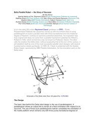
Self-Correcting Projectile Launcher: - Rensselaer Polytechnic Institute
Self-Correcting Projectile Launcher: - Rensselaer Polytechnic Institute
Self-Correcting Projectile Launcher: - Rensselaer Polytechnic Institute

You also want an ePaper? Increase the reach of your titles
YUMPU automatically turns print PDFs into web optimized ePapers that Google loves.
<strong>Self</strong>-<strong>Correcting</strong> <strong>Projectile</strong> <strong>Launcher</strong>:<br />
Progress Report for ECSE-4460 Control Systems Design<br />
Josh Schuster<br />
Yena Park<br />
Diana Mirabello<br />
Ryan Kindle<br />
March 30, 2005<br />
<strong>Rensselaer</strong> <strong>Polytechnic</strong> <strong>Institute</strong>
ABSTRACT<br />
The design of a <strong>Self</strong>-<strong>Correcting</strong> <strong>Projectile</strong> <strong>Launcher</strong> was motivated by the desire<br />
to improve the accuracy existing launchers without the use of extensive sensor networks,<br />
and to demonstrate the viability of an iterative learning algorithm for disturbance<br />
rejection. The goal is to fire a disc from a commercially available toy gun at a target, and<br />
have its accuracy improve with each subsequent shot until the target is struck precisely.<br />
As the disc strikes the touch screen, the error in the trajectory will be calculated based on<br />
the difference between the target and impact site, and the orientation of the launcher will<br />
be adjusted to compensate using a pan and tilt mechanism.<br />
ii
TABLE OF CONTENTS<br />
1. Introduction 1<br />
2. Preliminary Results 3<br />
2.1 Friction Identification. . . . . . . . . . . . . . . . . . . . . . . . . . . . . . . . . . . . . . . . .3<br />
2.2 Model Development . . . . . . . . . . . . . . . . . . . . . . . . . . . . . . . . . . . . . . . . . 9<br />
2.3 Validation . . . . . . . . . . . . . . . . . . . . . . . . . . . . . . . . . . . . . . . . . . . . . . . . .15<br />
2.4 Learning Algorithm. . . . . . . . . . . . . . . . . . . . . . . . . . . . . . . . . . . . . . . . . .21<br />
2.5 Subsystem Development. . . . . . . . . . . . . . . . . . . . . . . . . . . . . . . . . . . . . .28<br />
3. Summary of Progress 31<br />
3.1 Plan. . . . . . . . . . . . . . . . . . . . . . . . . . . . . . . . . . . . . . . . . . . . . . . . . . . . . . 31<br />
3.2 Schedule . . . . . . . . . . . . . . . . . . . . . . . . . . . . . . . . . . . . . . . . . . . . . . . . . 31<br />
3.3 Cost. . . . . . . . . . . . . . . . . . . . . . . . . . . . . . . . . . . . . . . . . . . . . . . . . . . . . . 32<br />
3.4 Unanticipated Challenges. . . . . . . . . . . . . . . . . . . . . . . . . . . . . . . . . . . . . 34<br />
3.5 Forecast. . . . . . . . . . . . . . . . . . . . . . . . . . . . . . . . . . . . . . . . . . . . . . . . . . . 35<br />
4. Bibliography 36<br />
5. Statement of Contribution 37<br />
Appendix A: MATLAB Code 38<br />
iii
LIST OF FIGURES<br />
2.1 Identification Simulink Model File . . . . . . . . . . . . . . . . . . . . . . . . . . . . . . . . . . .3<br />
2.2 Velocity Diagram without Filter. . . . . . . . . . . . . . . . . . . . . . . . . . . . . . . . . . . . . 4<br />
2.3 Velocity Diagram after Implementation of Second Filter. . . . . . . . . . . . . . . . . .5<br />
2.4 Velocity Diagram after Implementation of Third Filter for Tilt Axis. . . . . . . . .5<br />
2.5 Velocity Diagram after Implementation of Third Filter for Pan Axis. . . . . . . . .6<br />
2.6 Diagram of Torque vs. Steady State Velocity of Tilt Axis. . . . . . . . . . . . . . . . . 7<br />
2.7 Diagram of Torque vs. Steady State Velocity for Pan Axis. . . . . . . . . . . . . . . . 8<br />
2.8 Simulink Model File for the Parameter Equations. . . . . . . . . . . . . . . . . . . . . . . 9<br />
2.9 Angular Velocity Measured from the Tilt Motor. . . . . . . . . . . . . . . . . . . . . . . . 11<br />
2.10 Tilt Angular Velocity Simulated from the Model. . . . . . . . . . . . . . . . . . . . . . . .11<br />
2.11 Angular Velocity Measured from the Pan Motor. . . . . . . . . . . . . . . . . . . . . . . . 12<br />
2.12 Pan Angular Velocity Simulated from the Model. . . . . . . . . . . . . . . . . . . . . . . .12<br />
2.13 Parameter Equation Verification with Noise Consideration. . . . . . . . . . . . . . . .13<br />
2.14 <strong>Launcher</strong> Testing Procedure. . . . . . . . . . . . . . . . . . . . . . . . . . . . . . . . . . . . . . .15<br />
2.15 2 nd <strong>Launcher</strong> Testing Procedure. . . . . . . . . . . . . . . . .. . . . . . . . . . . . . . . . . . . . .16<br />
2.16 Plot of Short Range Trajectory Results. . . . . . . . . . . . . . . . . . . . . . . . . . . . . . . .18<br />
2.17 Average Vertical Displacement vs. Distance from <strong>Launcher</strong> to Target. . . . . . . 19<br />
2.18 Target Cones Resulting from Different Position Errors. . . . . . . . . . . . . . . . . . . 20<br />
2.19 Error Correction for Unusual Cases. . . . . . . . . . . . . . . . . . . . . . . . . . . . . . . . . . 22<br />
2.20 Distance to Edges of Touchpad. . . . . . . . . . . . . . . . . . . . . . . . . . . . . . . . . . . . . 23<br />
2.21 Learning Algorithm Chart. . . . . . . . . . . . . . . . . . . . . . . . . . . . . . . . . . . . . . . . . . 25<br />
2.22 Aluminum Mounting Base. . . . . . . . . . . . . . . . . . . . . . . . . . . . . . . . . . . . . . . . . .27<br />
2.23 Disc <strong>Launcher</strong>. . . . . . . . . . . . . . . . . . . . . . . . . . . . . . . . . . . . . . . . . . . . . . . . . . . 28<br />
2.24 Automated Firing. . . . . . . . . . . . . . . . . . . . . . . . . . . . . . . . . . . . . . . . . . . . . . . 28<br />
2.25 Mounting. . . . . . . . . . . . . . . . . . . . . . . . . . . . . . . . . . . . . . . . . . . . . . . . . . . . . 29<br />
iv
LIST OF TABLES<br />
1.1 System Specifications. . . . . . . . . . . . . . . . . . . . . . . . . . . . . . . . . . . . . . . . . . . . . .2<br />
2.1 Coulomb and Viscous Friction for Pan and Tilt Axes. . . . . . . . . . . . . . . . . . . . . 7<br />
2.2 Parameters for Pan and Tilt Axes. . . . . . . . . . . . . . . . . . . . . . . . . . . . . . . . . . . . .10<br />
2.3 Variation of the Parameters with respect to noise. . . . . . . . . . . . . . . . . . . . . . . . 13<br />
2.4 Disc Shooter Accuracy. . . . . . . . . . . . . . . . . . . . . . . . . . . . . . . . . . . . . . . . . . . . .15<br />
2.5 Preliminary Trajectory Results. . . . . . . . . . . . . . . . . . . . . . . . . . . . . . . . . . . . . . .16<br />
2.6 Short Range Trajectory Results. . . . . . . . . . . . . . . . . . . . . . . . . . . . . . . . . . . . . . 17<br />
2.7 Average Short Range Trajectory. . . . . . . . . . . . . . . . . . . . . . . . . . . . . . . . . . . . . 18<br />
2.8 Effect of Distance Change Due to Angle Change (x-direction) . . . . . . . . . . . . . 24<br />
2.9 Effect of Distance Change Due to Angle Change (y-direction). . . . . . . . . . . . . .24<br />
3.1 Pan and Tilt Mechanism Cost . . . . . . . . . . . . . . . . . . . . . . . . . . . . . . . . . . . . . . . 31<br />
3.2 Additional Parts Needed for System . . . . . . . . . . . . . . . . . . . . . . . . . . . . . . . . . . 32<br />
3.3 Labor Costs . . . . . . . . . . . . . . . . . . . . . . . . . . . . . . . . . . . . . . . . . . . . . . . . . . . . . 32<br />
3.4 Lab Usage . . . . . . . . . . . . . . . . . . . . . . . . . . . . . . . . . . . . . . . . . . . . . . . . . . . . . . 33<br />
3.5 Total System Costs . . . . . . . . . . . . . . . . . . . . . . . . . . . . . . . . . . . . . . . . . . . . . . . 33<br />
3.6 Actual Cost of System . . . . . . . . . . . . . . . . . . . . . . . . . . . . . . . . . . . . . . . . . . . . 33<br />
v
1. INTRODUCTION<br />
The world is an unpredictable place, and when it comes to projectile motion the<br />
unknowns one must take into account are numerous and complex. The purpose of the<br />
project proposed in this paper is to create a prototype <strong>Self</strong>-<strong>Correcting</strong> <strong>Projectile</strong><br />
<strong>Launcher</strong>. Instead of rejecting disturbances in advance to improve the chance of striking<br />
a target in a single shot, the system will fire repeatedly at a target and learn from its errors<br />
to strike more accurately with subsequent shots. The motivation for the project was to<br />
create a launcher that was capable of high accuracy but without the extensive sensor<br />
setup required to predict disturbances. The creation of such a system would be an<br />
economical solution for any number of applications, as well as a significantly more<br />
portable system.<br />
A trajectory may be altered by the varying currents, density, and stresses found in<br />
any given medium. While some of these may be measured and accounted for in advance,<br />
the variable nature of the environment dictates that no disturbance will be completely<br />
rejected. The measurements and computations to achieve such an incomplete error<br />
reduction would also require a significant investment in equipment. If an iterative<br />
learning approach were utilized instead, all that would be required to reject an error is the<br />
ability to sense to actual impact’s location relative to the target and extra projectiles.<br />
The design of projectile launchers is hardly a new endeavor; everything from<br />
batting cages to artillery has attempted to accurately hit a target. While small consumer<br />
systems such as a ping pong machine or batting cage lack sensory capabilities and rely<br />
instead on calibration, military applications are usually far more sophisticated. However,<br />
while guided artillery batteries are capable of rejecting disturbances through sensors and<br />
computers, smaller launchers such as mortars are not. The same desire for compactness<br />
and economy is what drives commercial applications to rely simply on calibration to<br />
ensure accuracy. Both commercial enterprises that market projectile launchers requiring<br />
accuracy as well as the military would benefit from a small cost-effective trajectory<br />
correction system.<br />
Since the purpose of the prototype is simply to demonstrate the viability of such a<br />
system, the most significant functional requirement is accuracy. The firing system must<br />
be above all be capable of consistently striking the same location when locked into a<br />
position, else the iterative learning algorithm will be unable to calculate corrections.<br />
Also, the pan and tilt mechanism used to aim the launcher must be able to accurately<br />
adjust and detect its orientation, and the controller must ensure that steady-state position<br />
error is near zero and that noise tolerance is high. To ensure that any error in the<br />
orientation is insignificant, the rise time, fall time and settling time of the control system<br />
should be low; the percent overshoot should be small but this is not a critical factor.<br />
Beyond the control system, the rotational velocity of the launcher is not a significant<br />
factor and as such will be kept low to allow for increased accuracy. The range of motion<br />
for the launcher will be sufficient to strike any target within range. The payload for the<br />
pan and tilt mechanism, specifically the launcher and its mounting apparatus, will be<br />
vi
made of plastic and aluminum and hence lightweight. The cost of the system will be low<br />
enough to allow for its widespread adaptation to the various low-cost applications<br />
discussed previously. Quantitative specifications are described in Table 1.1, with<br />
justification in the Preliminary Results section.<br />
Range of Motion (Pan) -180° to +180°<br />
Range of Motion (Tilt) -45° to +45°<br />
Rotational Accuracy ±0.1°<br />
Rotational Velocity 30° / s<br />
Steady State Error < 2%<br />
Noise Tolerance 98%<br />
Rise Time < 0.1 s<br />
Settling Time < 0.1 s<br />
Percent Overshoot < 15%<br />
Payload < 2 lbs<br />
Table 1.1: System Specifications<br />
The scope of effort required to realize the project proposed here is significant and<br />
diverse. The initial design and control of the pan and tilt mechanism require knowledge<br />
of control theory and modeling. Once that is accomplished, the implementation of the<br />
disturbance rejection system will integrate algorithm design skills, sensor development<br />
and trajectory planning. Beyond the control design, mechanical design skills will be used<br />
to create the mounting apparatus for the launcher, as well as to automate the firing of a<br />
projectile. Nonetheless, the project goal is attainable within the allocated timeframe.<br />
The preliminary results of the project show that model development is nearing<br />
completion, requiring only a few recalibrations once the launcher has been mounted. The<br />
automation of the firing system has been designed, and is ready to be implemented in the<br />
next week. The mount by which the system will be affixed to the pan and tilt mechanism<br />
has been designed and machined. Preliminary testing and calculation indicates that the<br />
system will be able to meet all of its specifications, and the transition into control design<br />
should begin shortly.<br />
Currently the project is slightly behind schedule. The delay is due in part to the<br />
break in the semester, during which less work than anticipated was accomplished, and the<br />
unavailability of necessary components. That has been the greatest setback to date, in<br />
that a cable to connect a laptop to the digital ports of the microcontroller, which will be<br />
used to automate firing, and the touch screen controller used in the previous year both<br />
required purchase. That set back the development and testing of the touch screen and<br />
learning algorithm, and may result in less time to test the system. Fortunately, it is not<br />
believed that these setbacks will affect the overall goal of the project beyond making the<br />
integration of the IR sensor an optional enhancement. The primary goal of using a<br />
learning algorithm to correct the trajectory of an object in flight should still be achievable<br />
within the remaining timeframe.<br />
vii
2. PRELIMINARY RESULTS<br />
2.1 Friction Identification<br />
Testing Procedure<br />
The purpose of the following Simulink model file shown in Figure 2.1 is to obtain<br />
necessary data for estimating Coulomb frictions and viscous frictions for tilt axis. The<br />
corresponding MATLAB code is located in Appendix A. For pan axis, the two inputs to<br />
the PCIM-DAS1602 16 block have to be swapped. PCI-QUAD04 has one output port<br />
that needs to be multiplied by 2π/(2048*4) to acquire theta which is the angle that motor<br />
points to after the command. Theta1 and thetadot1 corresponds to angle and the speed of<br />
tilt motor. Since the amount of torque that is required to start the system moving is<br />
greater than the torque required to keep the system moving in motion once it is already<br />
moving, an impulse was inputted 0.3 seconds after the simulation started with a pulse<br />
width of 0.01 seconds to break the static friction. Input voltage was incremented<br />
automatically with the ‘for loop’ from the script.<br />
Figure 2.1: Friction Identification Simulink Model File<br />
Some filtering was necessary because the velocity collected from a single<br />
simulation was fluctuating up and down. Figure 2.2 shows the raw data before the filter<br />
is applied. Filtering was implemented in three steps. First step was taking average from<br />
five runs for each voltage steps. And during second step, it took the average of the twenty<br />
five adjacent data points, from the data set that was calculated from first step. And<br />
viii
finally, the impulse spikes were eliminated. The data plot from Figure 2.3 is after first<br />
step of the filtering.<br />
For both pan and tilt axis, all velocities with input voltage greater than -0.5 volts<br />
and less than 0.5 volts saturated to zero. And velocities with input voltage greater than 1<br />
Volts or less than -1 volts all saturated to 9.3143 rad/s and -9.0014 rad/s for tilt axis,<br />
9.4629 rad/s and -9.1584 rad/s respectively for pan axis. The velocity diagrams for pan<br />
and tilt axis after all of the filtering was complete are shown in Figure 2.4 and 2.5.<br />
Figure 2.2: Velocity Diagram without Filter<br />
ix
Figure 2.3: Velocity Diagram after Implementation of Second Filter<br />
Figure 2.4: Velocity Diagram After Implementation of Third Filter for Tilt Axis<br />
x
Figure 2.5: Velocity Diagram After Implementation of Third Filter for Pan Axis<br />
Torque was calculated using following equation:<br />
Torque = Voltage * N * Nm * Kt*Ka<br />
Voltage = Input Voltage (-1~1 Volts)<br />
N = External Gear Ratio (2.47)<br />
Nm = Internal Gear Ratio (19.5)<br />
Kt = Motor Torque Constant (4.36e-2Nm)<br />
Ka = Amplifier Gain Constant (.1A)<br />
From Figure 2.6 and Figure 2.7, the Coulomb frictions and the viscous frictions<br />
are obtained. The Coulomb frictions are the two end points of the line where steady state<br />
velocity is zero, and the viscous frictions are the velocity of the line where it connects the<br />
maximum velocity to zero. From this fact, for the tilt axis, the negative Coulomb friction<br />
came out to be -0.1365Nm, and the positive Coulomb friction came out to be 0.115Nm.<br />
The negative viscous friction and positive viscous friction are 0.0082NmS/rad and<br />
0.0150NmS/rad respectively. These values are calculated using script attached in the<br />
back. Also for pan axis, negative Coulomb friction and positive Coulomb friction came<br />
out to be -0.0945Nm, and negative Coulomb friction came out to be 0.0735Nm. The<br />
negative viscous friction and positive viscous friction are 0.0218NmS/rad and<br />
0.0582NmS/rad as displayed in Table 2.1.<br />
xi
Axis<br />
Coulomb Friction (Nm)<br />
negative positive<br />
Viscous Friction (NmS/rad)<br />
negative positive<br />
Tilt Axis -0.1365 0.115 0.0082 0.0150<br />
Pan Axis -0.0945 0.0735 0.0218 0.0582<br />
Table 2.1: Coulomb and Viscous Friction for Pan and Tilt Axis<br />
Figure 2.6: Diagram of Torque vs. Steady State Velocity of Tilt Axis<br />
xii
Figure 2.7: Diagram of Torque vs. Steady State Velocity for Pan Axis<br />
Tolerance Analysis<br />
The data captured from the above procedure will not be in our project for two<br />
reasons. First because only the pan and tilt mechanism was tested without the firing<br />
mechanism since mounting the firing mechanism has not been done yet. The second<br />
reason is because the testing was done before the pulse width for impulse was given. The<br />
testing was done with the pulse width of 0.01 seconds when the suggested pulse width for<br />
impulse is 0.25 seconds. Further testing will be done using the impulse of 0.25 seconds<br />
to determine if it yields better results. Therefore, more accurate friction testing should be<br />
done once the mechanism is complete with the right value of pulse width.<br />
xiii
2.2 Model Development<br />
Friction Parameters<br />
θ + a <br />
1 θ L + a sgn( <br />
2 θ L ) = a3V<br />
+ a4<br />
sinθ<br />
L<br />
Equation 2.1<br />
The equation above was provided during the class lecture and the Simulink model<br />
file shown in Figure 2.8 is driven from it. The corresponding MATLAB code can be<br />
found in Appendix A. The chirp was used as input voltage which is a sinusoidal wave<br />
and it has frequency that increases from 0.1Hz to 10Hz in 20 seconds.<br />
Figure 2.8: Simulink Model File for the Parameter Equations<br />
Through some integrations and simplifications, matrices were developed in terms<br />
of θ , θ , V, sample time, and parameter a1, a2, a3, and a4.<br />
⎡−<br />
( 2 2<br />
θ + <br />
0 θ ) ∆t<br />
− ( θ + <br />
0 θ1<br />
) ∆t<br />
1<br />
2V0<br />
( θ1<br />
−θ<br />
) − −<br />
0<br />
⎤<br />
⎢ 2 2<br />
A =<br />
⎢−<br />
( θ1<br />
+ θ 2 ) ∆t<br />
− ( θ + <br />
1 θ ) ∆t<br />
2V<br />
2<br />
1(<br />
θ 2 −θ<br />
) − −<br />
⎥<br />
1<br />
⎥<br />
⎢<br />
⎢<br />
<br />
⎥<br />
⎥<br />
2 2<br />
⎢⎣<br />
− ( θ N −1<br />
+ θ N ) ∆t<br />
− ( θ + θ ) ∆t<br />
2VN<br />
−1(<br />
θ N −θ<br />
N −1)<br />
− − − ⎦ ) cos<br />
(cos 2<br />
2(cosθ1<br />
cosθ<br />
0 )<br />
2(cosθ<br />
2 cosθ1<br />
)<br />
<br />
θ N θ N 1<br />
N − 1<br />
N<br />
xiv
⎡ 2 2<br />
θ − ⎤<br />
1 θ 0<br />
⎡a1<br />
⎤<br />
⎢ ⎥<br />
⎢ 2 2<br />
θ − <br />
⎢ ⎥<br />
2 θ1<br />
⎥<br />
b = ⎢ ⎥ a = ⎢<br />
a2<br />
⎥<br />
a = pinv(A)*b<br />
⎢<br />
<br />
⎢a<br />
⎥ 3<br />
⎥<br />
⎢ ⎥<br />
⎢ 2 2 ⎥<br />
⎣θ<br />
N − θ N −1<br />
⎦<br />
⎣a4<br />
⎦<br />
The data which was achieved when the parameters, a1, a2, a3, and a4 were set to be<br />
random numbers, 1, 2, 3, and 4 respectively, was again used to calculate parameters using<br />
above method. a1 was calculated and came out to be 1.0053, a2 came out to be 1.7730, a3<br />
came out to be 2.8580, and a4 was came out to be 4.0053. All four parameters were very<br />
close to their original values. This proves that the above method is valid.<br />
With chirp input that was described in advance, thetas and angular velocities were<br />
obtained from pan and tilt mechanism. With this data, the parameters, a1 through a4<br />
were calculated for both pan and tilt axes.<br />
a1 a2 a3 a4<br />
tilt 128.9306 -566.2103 898.5276 121.5573<br />
pan 43 -23656 -12418 0<br />
Table 2.2: Parameters for pan and tilt axes<br />
Figures 2.9 through 2.12 below are the actual angular velocity and the angular<br />
velocity generated from modeling. The actual angular velocities are filtered in the same<br />
way as they were in friction identification through three filtering steps.<br />
xv
Figure 2.9: Angular velocity measured from the tilt motor<br />
Figure 2.10: Tilt Angular velocity simulated from the model<br />
xvi
Figure 2.11: Angular velocity measured from the pan motor<br />
Figure 2.12: Pan Angular velocity simulated from the model<br />
xvii
To consider the noise, random input was added to the theta. Results seemed to be<br />
close enough to the original value when the noise was less than 0.000001. Figure 2.13<br />
shows the Simulink diagram used.<br />
Figure 2.13: Parameter equation verification with noise consideration<br />
The table below shows how much the noise effects the parameters. The error is<br />
Parametermeasured − Parameteractual<br />
calculated using<br />
equation.<br />
Parameter<br />
actual<br />
noise gain a1 a2 a3 a4 error<br />
0.1 7 -1558 2952 -26884 -6513<br />
0.01 5.1 -138.5 205.1 2285.7 571.6416<br />
0.001 -48.7 -19.1 -63 -1281.5 -403.625<br />
0.0001 -132.732 -16.6409 -18.2091 -266.7625 -217.8127<br />
0.00001 -0.3162 1.3461 2.7369 0.7359 -2.546875<br />
0.000001 1.0444 1.9809 3.0036 4.0307 0.043725<br />
Table 2.3: Variation of the parameters with respect to noise<br />
xviii
Tolerance Analysis<br />
Even though it was very time consuming and difficult to finish, the actual data<br />
and the results from modeling do not match too well. There can be many factors that<br />
could contribute to the failure. Thus, the solution would be to collect the data until the<br />
most reasonable set is found. Moreover, noise should be considered after realistic<br />
parameters are found.<br />
xix
2.3 Validation<br />
<strong>Launcher</strong> Verification<br />
To verify that the toy disc shooter obtained would be consistent and accurate<br />
enough to be viable for use in our system a few tests were run. The first test was a simple<br />
test to determine consistency. Holding the gun on a level surface and aiming it at a pint<br />
glass on the same level surface, the gun was fired 5 times at a set distance. A diagram of<br />
this testing procedure can be seen in figure 2.14.<br />
Figure 2.14: <strong>Launcher</strong> Testing Procedure<br />
This was repeated for three trials for each distance. The number of times the disc<br />
hit the glass was recorded and the percent of that number out of 5 was put in the table.<br />
The Total Accuracy of the disc shooter at that set distance was then averaged from the<br />
averages obtained from the three trials. The results of this experiment are listed in Table<br />
2.4.<br />
Distance Try 1 Try 2 Try 3 Total Accuracy<br />
3ft 0.9m 100% 100% 100% 100%<br />
5ft 1.5m 80% 100% 100% 93.33%<br />
7ft 2.1m 80% 80% 80% 80%<br />
9ft 2.75m 80% 60% 80% 73.33%<br />
11ft 3.35m 80% 100% 80% 86.67%<br />
13ft 4m 60% 60% 40% 53%<br />
Table 2.4: Disc Shooter Accuracy<br />
xx
Finding the results of this first experiment satisfactory, it was decided that the disc<br />
shooter would be used. To obtain a more accurate understanding of how the disc is fired<br />
and how it travels a second test was designed to determine the trajectory of the disc after<br />
being launched from the toy gun. This experiment was set up very similarly to the<br />
previous one. The gun was held on a level surface and now aimed at a piece of paper<br />
with a graph drawn on it. This graph had marks for each centimeter vertically and<br />
horizontally away from the origin and was taped to the wall so that the origin was on the<br />
same level surface as that of the barrel of the toy gun. This experiment is diagrammed in<br />
figure 2.15<br />
Figure 2.15: 2 nd <strong>Launcher</strong> Testing Procedure<br />
The gun was fired 10 times at a set distance and the x and y coordinates where the<br />
disc hit were recorded for each shot. The gun was then moved to another set distance and<br />
theexperiment was repeated. The results of this experiment are listed in Table 2.5.<br />
x position<br />
in cm<br />
from<br />
origin<br />
0.5 m 1.0 m 1.5 m 2.0m<br />
y position<br />
in cm<br />
from<br />
origin<br />
x position<br />
in cm<br />
from<br />
origin<br />
y position<br />
in cm<br />
from<br />
origin<br />
x position<br />
in cm<br />
from<br />
origin<br />
y position<br />
in cm<br />
from<br />
origin<br />
x position<br />
in cm<br />
from<br />
origin<br />
y position<br />
in cm<br />
from<br />
origin<br />
Shot<br />
#<br />
1 -2 -1 0 -6 0 -10 X X<br />
2 -2 -1 0 -3 -1 -11 X X<br />
3 0 -1 1 -5 5 -9 X X<br />
4 -2 -2 -3 -5 2 -11 X X<br />
5 -1 -2 1 -5 1 -9 X X<br />
6 1 -1 -2 -5 -1 -10 X X<br />
7 -1 0 -3 -5 -1 -10 -1 -13<br />
8 -2 0 2 -4 2 -9 X X<br />
9 -2 0 0 -6 -2 -11 X X<br />
10 0 0 -2 -5 -2 -11 X X<br />
• x means the disc hit lower than -14cm and could not be recorded<br />
Table 2.5: Preliminary Trajectory Results<br />
The conclusion drawn from this experiment was that the trajectory should be<br />
determined from data collected between 0.5 and 1.5 meters. Anything before 0.5 meters<br />
will be fired at a negative angle and anything after 1.5 meters will be fired at a positive<br />
xxi
angle relative to the horizon. This led to the next experiment that was done in the exact<br />
same matter as above. The result of the trajectory experiment with data from 0.5 to 1.5<br />
meters is shown in Table 2.6. The experiment is graphed in Figure 2.16.<br />
0.5 m<br />
(x<br />
position<br />
in cm<br />
from<br />
origin)<br />
0.5 m<br />
(y<br />
position<br />
in cm<br />
from<br />
origin)<br />
0.7 m<br />
(x<br />
position<br />
in cm<br />
from<br />
origin)<br />
0.7 m<br />
(y<br />
position<br />
in cm<br />
from<br />
origin)<br />
0.9 m<br />
(x<br />
position<br />
in cm<br />
from<br />
origin)<br />
0.9 m<br />
(y<br />
position<br />
in cm<br />
from<br />
origin)<br />
Shot<br />
#<br />
1 -2 -1 1 -2 0 -4<br />
2 -2 -1 0 -2 2 -3<br />
3 0 -1 2 -2 -1 -5<br />
4 -2 -2 -2 -2 -2 -4<br />
5 -1 -2 4 -1 0 -3<br />
6 1 -1 3 -2 -1 -4<br />
7 -1 0 -2 -1 -1 -5<br />
8 -2 0 -2 -1 1 -3<br />
9 -2 0 -1 -2 3 -2<br />
10 0 0 3 0 0 -2<br />
1.0 m (x<br />
position<br />
in cm<br />
from<br />
origin)<br />
1.0 m (y<br />
position<br />
in cm<br />
from<br />
origin)<br />
1.1 m (x<br />
position<br />
in cm<br />
from<br />
origin)<br />
1.1 m (y<br />
position<br />
in cm<br />
from<br />
origin)<br />
1.3 m (x<br />
position<br />
in cm<br />
from<br />
origin)<br />
1.3 m (y<br />
position<br />
in cm<br />
from<br />
origin)<br />
1.5 m (x<br />
position<br />
in cm<br />
from<br />
origin)<br />
1.5 m (y<br />
position<br />
in cm<br />
from<br />
origin)<br />
0 -6 0 -5 0 -6 0 -10<br />
0 -3 -2 -6 -1 -7 -1 -11<br />
1 -5 -1 -6 -5 -6 5 -9<br />
-3 -5 -2 -8 -3 -10 2 -11<br />
1 -5 0 -5 -5 -10 1 -9<br />
-2 -5 0 -6 1 -5 -1 -10<br />
-3 -5 0 -6 2 -6 -1 -10<br />
2 -4 -1 -8 0 -8 2 -9<br />
0 -6 2 -7 2 -5 -2 -11<br />
-2 -5 -2 -7 -2 -9 -2 -11<br />
Table 2.6: Short Range Trajectory Results<br />
xxii
y-position (cm)<br />
Position of each individual trial disc at target from given distance<br />
4<br />
2<br />
0<br />
-6 -4 -2 0 2 4 6<br />
-2<br />
-4<br />
-6<br />
-8<br />
-10<br />
-12<br />
x-position (cm)<br />
Figure 2.16: Plot of Short Range Trajectory Results<br />
From 0.5 meters<br />
From 0.7 meters<br />
From 0.9 meters<br />
From 1.0 meters<br />
From 1.1 meters<br />
From 1.3 meters<br />
From 1.5 meters<br />
A summary of this experiment can be seen in the Table 2.7, which shows the<br />
average x and y positions at each distance in cm.<br />
0.5 m (x 0.5 m (y 0.7 m (x 0.7 m (y 0.9 m (x 0.9 m (y<br />
position) position) position) position) position) position)<br />
-1.1 -0.8 0.6 -1.5 0.1 -3.5<br />
1.0 m (x 1.0 m (y 1.1 m (x 1.1 m (y 1.3 m (x 1.3 m (y 1.5 m (x 1.5 m (y<br />
position) position) position) position) position) position) position) position)<br />
-0.6 -4.9 -0.6 -6.4 -1.1 -7.2 0.3 -10.1<br />
Table 2.7: Average Short Range Trajectory<br />
From this data, it can be concluded that the horizontal position of the disc stays<br />
relatively close to straight with a maximum of 1 cm average deviation from the origin. It<br />
can also be seen that as the distance from the target increases, the vertical position that<br />
the disc strikes the target also decreases. A plot of distance from target (in meters) vs.<br />
vertical position relative to the horizontal (in centimeters) is shown in Figure 2.17.<br />
xxiii
Average Vertical Displacement (cm)<br />
4<br />
2<br />
0<br />
-2<br />
-4<br />
-6<br />
-8<br />
-10<br />
-12<br />
Average Vertical Displacement vs. Distance from launcher to target<br />
0.5 0.7 0.9 1 1.1 1.3 1.5<br />
Distance from launcher to target (meters)<br />
Average<br />
Standard Deviation<br />
Figure 2.17: Average Vertical Displacement vs Distance from launcher to target<br />
Fitting a best-fit line to this data, the equation is found to be: Y = -9.5X +<br />
4.58571429, where X is the distance from the gun barrel to the target and Y would be the<br />
vertical displacement where the disc would hit the target. This equation is a good<br />
estimation of the trajectory of the disc knowing the distance to the target between 0.5 and<br />
1.5 meters. This equation can be used to estimate the vertical position at which the disc<br />
will strike the target if the distance from the launcher barrel to the target is known. This<br />
equation can also be used to estimate the distance the launcher is from the target given<br />
the vertical displacement of the striking area of the disc. A final use for this equation<br />
comes into the learning algorithm where knowing both the distance from the launcher to<br />
the target and the vertical displacement of the disc at the target, the algorithm can check<br />
the accuracy of the shot by comparing it with this model. This will later be expanded to<br />
range from zero to three meters after the disc launcher has been mounted and angled tests<br />
can be done.<br />
The size of the target will dictate the required accuracy for the system. The initial<br />
expectation is that the firing system be able to consistently hit within a 7.5 cm diameter<br />
circle at a maximum range of 1.5m, when at a zero degree tilt. Through simple<br />
trigonometry, it can be deduced that ensuring an impact within 3.25 cm of center at 1.5 m<br />
requires that the rotational position be within ±1.24 degrees. Taking into account the<br />
standard deviation of the horizontal deviations shown in Table 2.7 and Figure 2.17, the<br />
largest standard deviation was 2.60 cm, with the deviation at 1.5m being 2.21 cm. By<br />
subtracting the standard deviation from the allowable error, a circle of approximately 1<br />
cm radius is left, resulting in a maximum position error of ±0.382 degrees. The specified<br />
error of ±0.1 degrees falls well within the tolerable error, and should allow for the desired<br />
target to be hit at an even greater range with consistency. The mechanism itself should<br />
xxiv
have no difficulty achieving this low error, as the encoder allows for accuracy within<br />
0.0439 degrees since it has a 2048 bit quadrature reading on the output shaft. Figure 2.18<br />
shows the offset resulting from the possible position errors discussed above. Since the<br />
current trajectory of vertical motion is a best-fit line, it can be assumed that the same<br />
values will hold true for the tilt axis. These are likely to differ once a more precise<br />
trajectory can be calculated experimentally; however it appears that a ±0.1 degree error<br />
will supply the necessary accuracy and feasibility for the project.<br />
0.04<br />
0.03<br />
0.02<br />
0.01<br />
0<br />
-0.01<br />
X: 1.5<br />
Y: 0.01<br />
X: 1.5<br />
Y: -0.002618<br />
-0.02<br />
Target Cone<br />
Target Cone<br />
-0.03<br />
Allowable Error<br />
Allowable Error<br />
Desired Error<br />
Desired Error<br />
X: 1.5<br />
Y: -0.03246<br />
-0.04<br />
0 0.5 1 1.5<br />
Figure 2.18: Target Cones Resulting from Different Position Errors<br />
Since the control design has not yet been completed, it is not possible to do any<br />
tests on the rise time, settling time, steady state error, or percent overshoot. As such, the<br />
temporary values for those in the specification have been taken from the previous year’s<br />
project [1], as the application of the system is fairly similar, and for the time being, will<br />
serve our purposes until we can obtain more accurate values. Fortunately, the main<br />
criteria for the system is rotational accuracy, so any minor discrepancies in the actual<br />
specifications beyond that should be tolerable.<br />
xxv
2.4 Learning Algorithm<br />
Since it is not expected that the disc will hit the touchpad exactly on target the first time,<br />
an iterative learning algorithm is being developed in order to correct for any error that<br />
occurs. The learning algorithm is to be developed using MATLAB and Simulink<br />
software. It works by taking the touchpad data regarding the positional error and<br />
calculating new pan and tilt angles to reduce the error and hopefully hit the target on the<br />
next launch. If the disc does not hit the target on the next launch, the process is repeated<br />
with the error becoming smaller and smaller each time until the disc successfully hits the<br />
target.<br />
A learning algorithm requires that the launcher be repeatable. Unfortunately,<br />
initial testing results proved that the launcher used in this system is not perfectly<br />
repeatable. According to the initial launcher testing, there was some deviation of the<br />
point of impact when the launch was repeated under identical conditions. Even though<br />
that error occurs, it was determined that the launcher is a valid option for this project.<br />
Occasionally a disc will behave very irregularly when launched and will not follow a<br />
normal trajectory. This can cause a major problem when implementing a learning<br />
algorithm that assumes repeatability. If a normal trajectory at a specified pan and tilt<br />
angle would miss the target by two centimeters to the left, the correct action regarding<br />
error correction would be to correct for an error of two centimeters to the right along the<br />
x-axis. If, for example the disc were slightly bent, and curved more than usual because of<br />
this, then the same pan and tilt angle could end up yielding an error of ten centimeters to<br />
the left, even though the predicted trajectory would hit only two centimeters to the left. If<br />
that error of ten centimeters were corrected, there would be a large amount of overshoot<br />
in the correction. Assuming the next disc launches properly, it would hit the touchpad<br />
somewhere around 8 centimeters to the right of the target. The diagram in Figure 2.19<br />
should illustrate this more clearly.<br />
xxvi
Figure 2.19: Error Correction for Unusual Cases<br />
In order to compensate for this problem, the learning algorithm will check for<br />
accuracy so that it can be determined whether or not the particular launch is an unusual<br />
case. Once the gun is mounted, more extensive testing of the launcher should be possible<br />
and advanced trajectory equations will be obtained. With more testing once the launcher<br />
is mounted, an advanced trajectory system can be obtained. The advanced trajectory<br />
equations should be able to predict a point of impact for a disc launched at any given<br />
distance and pan and tilt angle. This predicted point of impact will not be completely<br />
accurate since the launcher is not perfectly repeatable, however, it should yield a good<br />
estimate of where the disc should hit the touchpad. The actual point of impact is<br />
compared to the point predicted by the advanced trajectory to determine if that particular<br />
launch is within the range of accuracy. If the point of impact is found to be outside the<br />
range of accuracy, then the launch will be considered inaccurate and no error correction<br />
will occur. After the initial testing, it was determined that the range of accuracy will be<br />
within a 6 cm of the projected point of impact in both the x and the y direction.<br />
According to the initial launcher testing results shown in Table 2.6 in the launcher<br />
verification section, the maximum distance between observed points of impact at any<br />
distance was 6 cm. Once the gun is mounted and the touchpad controller is obtained,<br />
more additional testing will be needed to confirm that 6 cm is a suitable accuracy range.<br />
If the launch is outside that radius, no error correction will occur and another disc will be<br />
launched at that pan and tilt angle.<br />
xxvii
If a launch is determined to be accurate, the learning algorithm will then use the<br />
data from the touchpad regarding the Cartesian Coordinates of the point of impact and the<br />
center of the target to calculate the error in the x and y direction. Inverse kinematics are<br />
then used to transform the distance from the point of impact to the center of the target<br />
into a desired pan and tilt angle. The distance in Cartesian Coordinates in the X direction<br />
will be converted into a desired pan angle and the distance in the Y direction will be<br />
converted to a desired tilt angle.<br />
A potential problem is the fact that the distance will change slightly as the pan or<br />
tilt angle changes due to the fact that the touchpad is flat. Figure 2.20 shows that the<br />
distance will be slightly greater when aiming at a point nearer to the edge of the touchpad<br />
since the equilibrium position will be pointed directly at the center of the touchpad. The<br />
principle is the same for the x-direction and the y-direction.<br />
Figure 2.20: Distance to Edge of Touchpad<br />
The touchpad is 30 centimeters wide and therefore the maximum distance from<br />
the center in the x direction is positive or negative 15 cm. It is 20 cm high and therefore<br />
the maximum change in vertical distance is positive or negative 10 cm. Table 2.8 shows<br />
the positional changes in point of impact that would be predicted as a result of the slight<br />
changes in distance due to pointing at the edge of the touchpad. Calculations were only<br />
done for the points at the very edges of the touchpad because those points give the<br />
maximum change that would occur. The original values for the deviation from x = 0 and<br />
y = 0 at the equilibrium angle were taken from Table 2.7 in the launcher verification<br />
section.<br />
xxviii
Effects of Aiming at the Edges of the Touchpad (x-direction)<br />
Dist. From pad (equillibrium)<br />
(in m)<br />
Pan angle require to point at 15<br />
0.5 0.7 0.9 1.0 1.1 m 1.3 1.5<br />
cm in x-direction (degrees)<br />
Distance from pad (pointed at 15<br />
16.700 12.094 9.462 8.531 7.765 6.582 5.711<br />
cm) (in m)<br />
Deviation y = 0 at 0 degrees<br />
0.522 0.716 0.912 1.011 1.110 1.309 1.507<br />
(equilibrium) (in meters) -0.008 -0.015 -0.035 -0.049 -0.064 -0.072 -0.101<br />
Deviation y = 0 at the pan angle<br />
- -<br />
required to point at 15 cm (in m) -0.0085 0.0155 0.0357 -0.0498 -0.0649 -0.0727 -0.1017<br />
Difference (m)<br />
Deviation from x = 0 at 0 degree<br />
..0005 0.0005 0.0007 0.0008 0.0009 0.0007 0.0007<br />
pan angle (in meters)<br />
Deviation x = 0 at the pan angle<br />
-0.011 0.006 0.001 -0.006 -0.006 -0.011 0.003<br />
required to point at 15 cm (in m) -0.0117 0.0062 0.001 -0.0061 -0.0061 -0.011 0.003<br />
Difference 0.0007 0.0002 0 0.0001 0.0001 0 0<br />
Table 2.8: Effect of Distance Change due to Angle Change(x-direction)<br />
Effects of Aiming at the Edges of the Touchpad (x-direction)<br />
Dist. From pad (equillibrium)<br />
(in m)<br />
Tilt angle require to point at 10<br />
0.5 0.7 0.9 1.0 1.1 m 1.3 1.5<br />
cm in y-direction (degrees)<br />
Distance from pad (pointed at 10<br />
11.310 8.130 6.340 5.711 5.194 4.399 3.814<br />
cm) (in m)<br />
Deviation y = 0 at 0 degrees<br />
0.510 0.707 0.906 1.005 1.105 1.304 1.503<br />
(equilibrium) (in meters) -0.008 -0.015 -0.035 -0.049 -0.064 -0.072 -0.101<br />
Deviation y = 0 at the pan angle<br />
- -<br />
required to point at 15 cm (in m) -0.0084 0.0153 0.0356 -0.0498 -0.0647 -0.0726 -0.1017<br />
Difference (m)<br />
Deviation from x = 0 at 0 degree<br />
..0004 0.0003 0.0006 0.0008 0.0007 0.0006 0.0007<br />
pan angle (in meters)<br />
Deviation x = 0 at the pan angle<br />
-0.011 0.006 0.001 -0.006 -0.006 -0.011 0.003<br />
required to point at 15 cm (in m) -0.0115 0.0061 0.001 -0.0061 -0.0061 -0.011 0.003<br />
Difference 0.0005 0.0001 0 0.0001 0.0001 0 0<br />
Table 2.9: Effect of Distance Change due to Angle Change(y-direction)<br />
The changes in predicted point of impact due to changes in distance to touchpad<br />
resulting from a change in angle are on the order of 10^-4 and are therefore negligible<br />
since they are very small compared to the deviations from x = 0 and y = 0. Therefore, the<br />
change in distance to the touchpad need not be taken into account.<br />
xxix
A flow chart depicting the learning algorithm is displayed in Figure 2.21<br />
Figure 2.21: Learning Algorithm Chart<br />
In summary, the learning algorithm will work as follows. The initial disc will be<br />
launched at the touchpad. Using the advanced trajectory models, the projected point of<br />
impact for the given distance and angles will be calculated in Cartesian coordinates.<br />
When the disc hits the touch pad, the touchpad will give back data regarding the actual<br />
point of impact, and the location of the target. First the actual point of impact will be<br />
compared to the projected point of impact. If the actual point of impact is greater then<br />
xxx
6 cm away from the projected point of impact in either the x or the y direction, the launch<br />
will be considered an unusual case and determined inaccurate and another launch will<br />
take place. If the point of impact is within the range of accuracy then the error is<br />
computed using the data from the touchpad. The error will be given in terms of Cartesian<br />
Coordinates and therefore has to be transformed into a desired pan and tilt angle using<br />
inverse kinematics. Once the desired pan and tilt angle is reached, another disc is<br />
launched. If this next disc hits the target, then the process is complete. If the disc does not<br />
hit the target, the process repeats itself until a launch successfully hits the target.<br />
xxxi
2.5 Subsystem Development<br />
Mounting and Automated Firing<br />
To mount the launcher to the pan and tilt mechanism and allowing for automated<br />
firing required a whole new look at out system. First a way to mount the launcher to a flat<br />
surface that could pan and tilt was necessary. The design in Figure 2.22 illustrates the<br />
solution to this problem.<br />
Figure 2.22: Aluminum Mounting Base<br />
We’ve since acquired a proper sized piece aluminum stock and cut and drilled it<br />
to specifications. The drilled hole in the bottom is where the shaft of the tilt axis will slide<br />
through and be set-screwed securely on. Once this is in place, a flat surface perpendicular<br />
to the tilt shaft is now available to mount the launcher on.<br />
Next we reduced the launcher to only it’s necessary components for firing discs.<br />
An illustration of this piece can be seen in Figure 2.23. By simply connecting the disc<br />
spinning motor to a power source, the launcher can now fire discs as before with less<br />
weight, drag, and a now flat and easily mountable surface.<br />
xxxii
Figure 2.23: Disc <strong>Launcher</strong><br />
This reduction of the launcher removed our trigger, but this actually aided in the<br />
mounting process. Now, by simply connecting a DC motor to the gear on the bottom of<br />
our launcher, the motor will turn a set distance, which will turn the gear, which will then<br />
push the disc into the launching chamber causing it to fire when it meets the spinning<br />
wheel powered by the motor on the launcher. See figure 2.24. By simply reversing the<br />
voltage on the DC motor for the same set time, the gun can reload also.<br />
Figure 2.24: Automated Firing<br />
Now to fit the motor in between the base and launcher simple screws, nuts, and<br />
washers will be all that is needed. The motor will screw into position on the base. Then<br />
the launcher will be placed above it and the gear on the motor aligned with the gear on<br />
the launcher arm. This will be then screwed into the base, using the screws to suspend the<br />
xxxiii
launcher in the air while holding it firmly onto the base, the long screw length acting as<br />
spacers for the motor. Figure 2.25 demonstrates the mounting of our launching system on<br />
the pan and tilt mechanism.<br />
Figure 2.25: Mounting of System<br />
xxxiv
3. SUMMARY OF PROGRESS<br />
3.1 Plan<br />
For the most part, the initial plan has remained unchanged. When complete, the<br />
system should be able to successfully launch a disc at a touchpad and implement a<br />
learning algorithm to correct for the error; eventually having the foam disc hit the target.<br />
Other than delays in needed components of the system, the project seems to be<br />
moving along well. Though this has slowed progress down and pushed the schedule back,<br />
no more setbacks of this nature are expected. An anticipated change to the original plan<br />
of action may be the removal of the IR sensor since, at this point, it is not looking like<br />
there will be sufficient time to complete it. The IR sensor is an added component that will<br />
only be utilized if time permits. Though we may have to play catch-up in the next couple<br />
of weeks, completion of our project on time is still very feasible.<br />
3.2 Schedule<br />
Thus far the plan of action has been followed very closely and seems to be<br />
working out well for the most part. Unfortunately a few tasks are slightly behind<br />
schedule and this has held up progress on some aspects of this project somewhat. The<br />
mounting and automatic firing of the disc launcher is behind due to slow retrieval of<br />
necessary materials such as the aluminum stock and DC motor. This will be finished this<br />
week, about 2 weeks late. The advanced trajectory model will then be next; it depends on<br />
the mounting of the gun so therefore cannot be started until the mounting is completely<br />
finished. The modeling and simulation has been continually progressing and is still<br />
advancing according to schedule. The learning algorithm is in the process of being<br />
developed and is currently progressing according to schedule. At this point, all of the<br />
necessary parts for the system have been obtained except a controller for the touchpad.<br />
The original plan was to use the touchpad controller used by the group that worked with<br />
the touchpad last year, however this was unable to be found. Due to this, touchpad<br />
testing and development will be delayed about a week.<br />
For our modeling and simulation, Yena and Diana have completed some more<br />
friction identification and parameter identification. They have also begun work on the<br />
modeling of the pan and tilt mechanism. Ryan has begun calibration and kinematics and<br />
is learning about employing the touchpad. Josh has begun physical modeling and has<br />
created and obtained all necessary parts for the mounting and automatic firing of the disc<br />
launcher. These are all necessary initial phases in our plan of action. We are currently<br />
working on completing these and have even begun some work in the next phase of our<br />
plan of action. We have obtained the touchpad and are seeking a controller for it and we<br />
have begun to design and develop the learning algorithm.<br />
xxxv
3.3 Cost<br />
As for cost of the system, our analysis was quite accurate. The touchpad cost us a<br />
total of $25.00, off .05 from our $24.95 estimate. Also, our DC motor only cost us $3.00,<br />
a savings of $2.50 off our original estimate. However, having to purchase a controller for<br />
our touchpad now seems highly probable. This is an extra cost we did not budget for and<br />
is now estimated to cost us $40. The updated cost of the assembled pan and tilt system<br />
used as the basis of this project has been itemized and calculated as follows in Table 3.2.<br />
Item<br />
Motor<br />
Timing Belt<br />
Part Number Price ($) Quantity Total ($)<br />
GM8724S017 192.86 [1] 2 385.72<br />
A6Z16-C01806 1.86 [1] 2 2.70<br />
Encoder<br />
S1 & S2 Optical Shaft 49.00 [3]<br />
Encoders<br />
2 98.00<br />
Gear<br />
A6A6-75NF01812 15.15 [1] 2 30.30<br />
A6A6-25DF01806 7.76 [1] 2 15.52<br />
Total 532.24<br />
Table 3.1: Pan and Tilt Mechanism Cost<br />
The costs of additional parts and programs needed for our complete system<br />
beyond those of the assembled pan and tilt mechanism are listed in Table 3.3.<br />
xxxvi
Item<br />
Toy Disc Shooter and Discs<br />
Touchpad<br />
Touchpad Controller<br />
Wires (spool)<br />
Programs:<br />
SolidWorks<br />
MATLAB 7<br />
Simulink 6<br />
Motor [6]<br />
Gears [6]<br />
Sensors:<br />
Infrared LED [5]<br />
Infrared Detector [5]<br />
Clamps (for Mounting)<br />
TOTAL<br />
Price ($) Quantity Total<br />
4.97 2 9.94<br />
24.95 [4]<br />
40.00<br />
1 24.95<br />
40.00<br />
4.00 1 4.00<br />
64.98 [7]<br />
1900.00[2]<br />
2800.00[7]<br />
3.00<br />
2.25<br />
0.60<br />
2.75<br />
1<br />
4<br />
4<br />
1<br />
1<br />
2<br />
1<br />
64.98<br />
7,600.00<br />
11,200.00<br />
3.00<br />
2.25<br />
1.20<br />
2.75<br />
8.95 1 8.95<br />
Table 3.3: Additional Parts Needed for System<br />
18,962.03<br />
The labor cost of designing, building, testing and operating the system among the<br />
four members of this group project are listed in Table 3.4.<br />
Laborer Salary ($/hr) Hours/Week Weeks Total ($)<br />
Ryan Kindle<br />
25 10 10 2,500<br />
Diana Mirabello<br />
Yena Park<br />
Josh Schuster<br />
Total for 4 Employees ($)<br />
25 10 10 2,500<br />
25 10 10 2,500<br />
25 10 10 2,500<br />
Table 3.4: Labor Costs<br />
10,000<br />
xxxvii
The use of different labs to build and test our system has been assumed to cost as<br />
follows in Table 3.5 and the total system costs are listed in Table 3.6.<br />
Lab Rate ($/day) Use (days) Total ($)<br />
Control Systems Lab 50 30 3,000<br />
Engineering Lab<br />
50 4 200<br />
Total 3,200<br />
Table 3.5: Lab Usage<br />
Pan and Tilt<br />
Mechanism<br />
$532.24<br />
Additional Parts Needed for<br />
System<br />
Labor Costs Lab Use Total<br />
$18,922.02 $10,000 $3,200 $32,694.26<br />
Table 3.6: Total System Costs<br />
Seeing as many of the components, programs, labs and equipment are provided<br />
free of charge, along with the fact that there is no labor cost, the actual cost to our group<br />
can be calculated and are displayed in Table 3.7.<br />
Pan and Tilt<br />
Mechanism<br />
$0<br />
Additional Parts Needed for<br />
System<br />
Labor Costs Lab Use Total<br />
$97.04 $0 $0 $97.04<br />
3.4 Unanticipated Challenges<br />
Table 3.7: Actual Cost of System<br />
During the development of the system, a few unanticipated challenges have come<br />
up. The first was with the touchpad control. It was expected that the touchpad controller<br />
from last year’s team could be used, however that controller has yet to be found. This<br />
caused some delay in obtaining a controller because now it has to be ordered and<br />
researched. Another challenge was in the mounting of the system. A chunk of aluminum<br />
stock was needed to make the base for the launcher to sit on, however there was some<br />
difficulty in obtaining this because the machine shop did not have it readily available.<br />
Another challenge encountered was with the automated firing of the mechanism. There<br />
has been some difficulty in hooking the DC motor up to the xpc target so that it can be<br />
controlled through MATLAB and Simulink .<br />
xxxviii
3.5 Forecast<br />
For the remainder of the project, we consider it reasonable to predict that we will<br />
have a working automated disc launcher by the end of the semester. We will be able to<br />
automate the firing and implement the learning algorithm. We currently do not believe<br />
that we will be able to complete the IR sensor for initial sensing of the location of the<br />
touchpad and therefore the first launch will most likely be aimed manually. Since there<br />
have been a few setbacks with some aspects of this project, we feel that it is in our best<br />
interest to concentrate on catching up with our original schedule and successfully<br />
completing all of parts of the project which we consider to be the most important. It is<br />
reasonable for us to predict that we will get all of the other aspects of the project done<br />
successfully.<br />
xxxix
4. BIBLIOGRAPHY<br />
[1] Bowen, Luke, Cieloszyk, Matt and Gillette, Rob. “Team 5 Proposal.” Team 5<br />
Proposal. 2/22/2004.<br />
http://www.cat.rpi.edu/~wen/ECSE4962S04/proposal/team5proposal.pdf<br />
[2] Strassberg, Dan. “Math, simulation updates offer new programming tools, faster<br />
development.” EDN.com. 6/10/2004. http://www.edn.com/article/CA421495.html<br />
[3] Wen, John. “S1 & S2 Optical Shaft Encoders.” Encoder Datasheet. 9/26/02.<br />
http://www.cat.rpi.edu/~wen/ECSE4962S03/encoder_datasheet.pdf<br />
[4] “Action Solutions.” Action Solutions. 2004.<br />
http://www.actionsolutions.com/subcat.asp?departmentid=74<br />
[5] “High Power Infrared LEDs.” Reynolds Electronics. 2000.<br />
http://www.rentron.com/Products/Electronic-Components.htm<br />
[6] “Motors, Servos, Wheels and H-Bridges Section.” Hobby Engineering. 2/28/2005.<br />
http://www.hobbyengineering.com/SectionM.html<br />
[7] “SolidWorks Student Edition 2004-2005.” JourneyEd.com. 2004.<br />
http://www.journeyed.com/itemDetail.asp?GEN0=01&GEN1=01&GEN2=SOLI<br />
DWORKS&GEN3=JEM&T1=36785643FS6<br />
xl
5. Statement of Contribution<br />
Here is the breakdown for who wrote the various sections of this report<br />
Introduction Ryan Kindle<br />
Friction Identification Yena Park<br />
Model Development Yena Park<br />
Validation Josh Schuster<br />
Ryan Kindle<br />
Learning Algorithm Diana Mirabello<br />
Subsystem Development Josh Schuster<br />
Summary of Progress Josh Schuster<br />
Compiling and Editing Diana Mirabello<br />
______________________________<br />
Josh Schuster<br />
______________________________<br />
Yena Park<br />
______________________________<br />
Diana Mirabello<br />
______________________________<br />
Ryan Kindle<br />
xli
Appendix A<br />
MATLAB Code<br />
%%%%%%%%%%%%%%%%%%%%%%%%%%%%%%%%%%%%%%%%%%%<br />
%friction_param_setup.m<br />
%02/26/05<br />
%By Yena Park<br />
%set the initial values for friction_param.mdl<br />
%put the logs on the signals<br />
%subsystem under friction_param.mdl needs to be selected before running this file<br />
%%%%%%%%%%%%%%%%%%%%%%%%%%%%%%%%%%%%%%%%%%%<br />
ts = 0.001; %sample time<br />
const_voltage = 1;<br />
peak_voltage =10;<br />
handles = get_param(gcb, 'porthandles');<br />
outputports = handles.Outport;<br />
for i = 1 :length(outputports)<br />
set_param(outputports(i), 'DataLogging', 'on');<br />
set_param(outputports(i), 'TestPoint', 'on');<br />
end<br />
set_param(outputports(1), 'Name', 'theta1_log');<br />
set_param(outputports(2), 'Name', 'thetadot1_log');<br />
set_param(outputports(3), 'Name', 'theta2_log');<br />
set_param(outputports(4), 'Name', 'thetadot2_log');<br />
set_param(outputports(5), 'Name', 'voltage_log');<br />
xlii
%%%%%%%%%%%%%%%%%%%%%%%%%%%%%%%%%%%%%%%%%%%<br />
%friction_param_save.m<br />
%02/26/05<br />
%By Yena Park<br />
%run friction_param.mdl in a for loop<br />
%collect the data and plot it<br />
%%%%%%%%%%%%%%%%%%%%%%%%%%%%%%%%%%%%%%%%%%%<br />
voltage_range = [-1:.05:1];<br />
times = [0:0.001:5];<br />
for k = 1:length(voltage_range)<br />
voltage_range(k)<br />
for i = 1 : 5<br />
setparam(tg, 28, voltage_range(k));<br />
i<br />
if voltage_range(k)==0<br />
else<br />
if voltage_range(k)>0<br />
setparam(tg, 27, 10);<br />
setparam(tg, 24, 10);<br />
else<br />
setparam(tg, 27, -10);<br />
setparam(tg, 24, -10);<br />
end<br />
start(tg);<br />
pause(5);<br />
stop(tg);<br />
outputlog = tg.OutputLog;<br />
theta_1(i, :) = outputlog(:, 1);<br />
theta_dot_1(i, :) = outputlog(:, 2);<br />
voltage_out(i, :) = outputlog(:, 5);<br />
pause(.5);<br />
end<br />
end<br />
%first filtering<br />
thetadot_ave_temp(k, :) = (theta_dot_1(1, :)+theta_dot_1(2, :)+theta_dot_1(3,<br />
:)+theta_dot_1(4, :)+theta_dot_1(5, :))/5;<br />
%second filtering<br />
xliii
for j = 1 : length(thetadot_ave_temp(k, :)) - 25<br />
sum = 0;<br />
for ii = 0 : 24<br />
sum = sum + thetadot_ave_temp(k, j+ii);<br />
end<br />
thetadot_ave(k,j) = sum/25;<br />
end<br />
end<br />
%third filtering<br />
for i = 1 : 41<br />
for j = 1 : 4975<br />
if abs(thetadot_ave(i, j) - thetadot_ave(i, j+1))>1<br />
thetadot_ave(i, j +1) = (thetadot_ave(i, j) + thetadot_ave(i, j + 2))/2;<br />
end<br />
end<br />
end<br />
for i = 1 : 25<br />
plot(times(1:4976), thetadot_ave(i, :));<br />
hold on;<br />
end<br />
ylabel('thetadot');<br />
xlabel('second');<br />
title('Tilt Axis');<br />
save tilt_axis.mat thetadot_ave_temp thetadot_ave<br />
xliv
%%%%%%%%%%%%%%%%%%%%%%%%%%%%%%%%%%%%%%%%%%%<br />
%steady_state1.m<br />
%2/27/05<br />
%By Yena Park<br />
%calculate steady state velocity<br />
%calculate torque<br />
%plot torque vs. velocity<br />
%calculate frictions<br />
%%%%%%%%%%%%%%%%%%%%%%%%%%%%%%%%%%%%%%%%%%%<br />
voltage = [-1:.05:1];<br />
%calculate Torque<br />
N1 = 2.47; %External Gear Ratio<br />
Nm1 = 19.5; %Internal Gear Ratio<br />
Kt = 4.36e-2; %motor torque constant<br />
Ka = .1; %amplifier gain constant<br />
torque = voltage .* N1 * Nm1 * Kt * Ka;<br />
k = 1;<br />
positive = 0;<br />
viscous_friction_negative_sum = 0;<br />
viscous_friction_positive_sum = 0;<br />
negative_count = 0;<br />
positive_count = 0;<br />
for i = 1 : 22<br />
thetadot1_ss(i) = 0;<br />
for j = 4976-1000:4976<br />
thetadot1_ss(i) = thetadot1_ss(i) + thetadot1_ave(i, j)/1000;<br />
end<br />
if abs(thetadot1_ss(i)) < 0.0001<br />
save_torque(k) = torque(i);<br />
k = k + 1;<br />
positive = 1;<br />
elseif i ~= 1 && abs(thetadot1_ss(i) - thetadot1_ss(i-1))>0.05<br />
if positive ==0<br />
viscous_friction_negative_sum = viscous_friction_negative_sum + (torque(i)torque(i-1))/(thetadot1_ss(i)-thetadot1_ss(i-1));<br />
negative_count = negative_count + 1;<br />
else<br />
xlv
viscous_friction_positive_sum = viscous_friction_positive_sum + (torque(i)torque(i-1))/(thetadot1_ss(i)-thetadot1_ss(i-1));<br />
positive_count = positive_count + 1;<br />
end<br />
end<br />
end<br />
coulomb_friction_negative_tilt = save_torque(1);<br />
coulomb_friction_positive_tilt = save_torque(k-1);<br />
viscous_friction_negative_tilt = viscous_friction_negative_sum/negative_count;<br />
viscous_friction_positive_tilt = viscous_friction_positive_sum/positive_count;<br />
plot(thetadot1_ss, torque)<br />
xlabel('steady state velocity')<br />
ylabel('torque');<br />
title('Tilt Axis');<br />
xlvi
%%%%%%%%%%%%%%%%%%%%%%%%%%%%%%%%%%%%%%%%%%%<br />
%param_save_tilt.m<br />
%3/25/05<br />
%By Yena Park<br />
%to obtain the theta, thetadot, and inputvoltage<br />
%to filter the thetadot<br />
%%%%%%%%%%%%%%%%%%%%%%%%%%%%%%%%%%%%%%%%%%%<br />
clear theta2 thetadot2 voltage_in voltage_in_sum theta2_sum thetadot2_sum<br />
voltage_in_ave theta2_ave thetadot2_ave<br />
times = [0:0.001:20];<br />
for k = 1:10<br />
start(tg);<br />
pause(20);<br />
stop(tg);<br />
outputlog = tg.OutputLog;<br />
theta1(k,:) = outputlog(:, 1);<br />
thetadot1(k, :) = outputlog(:, 2);<br />
voltage_in(k, :) = outputlog(:, 5);<br />
pause(0.5);<br />
end<br />
voltage_in_sum(1:14285) = 0;<br />
theta1_sum(1:14285) = 0;<br />
thetadot1_sum(1:14285) = 0;<br />
for i = 1 : 10<br />
voltage_in_sum = voltage_in_sum + voltage_in(i, :);<br />
theta1_sum = theta1_sum + theta1(i, :);<br />
thetadot1_sum = thetadot1_sum + thetadot1(i, :);<br />
end<br />
voltage_in_ave = voltage_in_sum / 10;<br />
theta1_ave = theta1_sum/10;<br />
thetadot1_ave = thetadot1_sum/10;<br />
xlvii
%%%%%%%%%%%%%%%%%%%%%%%%%%%%%%%%%%%%%%%%%%%<br />
%param_calculation.m<br />
%3/26/05<br />
%By Yena Park<br />
%to get the parameters<br />
%%%%%%%%%%%%%%%%%%%%%%%%%%%%%%%%%%%%%%%%%%%<br />
theta = logsout.theta;<br />
theta_Data = theta.Data;<br />
voltage = logsout.voltage;<br />
voltage = voltage.Data;<br />
ts = 0.001;<br />
for j = 1 : length(theta_Data)-1<br />
thetadot_Data(j) = (theta_Data(j+1) - theta_Data(j))/ts;<br />
end<br />
for i = 1 : length(theta_Data)-2<br />
col1 = -(thetadot_Data(i)^2 + thetadot_Data(i+1)^2)*ts;<br />
col2 = -(abs(thetadot_Data(i)) + abs(thetadot_Data(i+1)))*ts;<br />
col3 = 2*voltage(i)*(theta_Data(i+1) - theta_Data(i));<br />
col4 = -2*(cos(theta_Data(i+1)) - cos(theta_Data(i)));<br />
A(i, :) = [col1 col2 col3 col4];<br />
b(i) = thetadot_Data(i+1)^2 - thetadot_Data(i)^2;<br />
end<br />
a = pinv(A)*b'<br />
xlviii