

ND 1400 QUADRA-CHEK - heidenhain - DR. JOHANNES ...
ND 1400 QUADRA-CHEK - heidenhain - DR. JOHANNES ...
ND 1400 QUADRA-CHEK - heidenhain - DR. JOHANNES ...

Create successful ePaper yourself
Turn your PDF publications into a flip-book with our unique Google optimized e-Paper software.
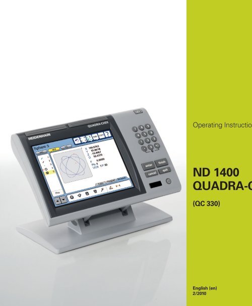
Operating Instructions<br />
<strong>ND</strong> <strong>1400</strong><br />
<strong>QUA<strong>DR</strong>A</strong>-<strong>CHEK</strong><br />
(QC 330)<br />
English (en)<br />
2/2010
QC-330 Series<br />
User’s Guide<br />
Touch Probe Systems<br />
QC-330 and QC-331
QC-330 Series Touch Probe Systems<br />
User’s Guide<br />
Published by<br />
Metronics, Inc.<br />
30 Harvey Road<br />
Bedford, New Hampshire 03110<br />
www.metronics.com<br />
User’s Guide part number: 11A10609 Revision 0<br />
Publishing date: June, 2008<br />
Printed in United States of America<br />
Copyright © 2008 by Metronics, Inc., Bedford, New Hampshire<br />
QC-330 software version: 1.40<br />
All information set forth in this document, all rights to such information, any and all inventions disclosed<br />
herein and any patents that might be granted by employing the materials, methods, techniques or apparatus<br />
described herein are the exclusive property of Metronics Inc., Bedford, New Hampshire.<br />
Terms, conditions and features referenced in this document are subject to change without notice.<br />
No part of this document may be reproduced, stored in a retrieval system, or transmitted in any form or by<br />
any means, electronic, mechanical, photocopying, recording, or otherwise, without prior written permission<br />
of Metronics, Inc.. Requests to Metronics, Inc. for permission should be addressed to the Technical<br />
Services Department, Metronics, Inc., 30 Harvey Road, Bedford, New Hampshire 03110.<br />
Limit of liability and disclaimer of warranty<br />
While this guide was prepared with great care, Metronics makes no representations or warranties with<br />
respect to the accuracy or completeness of the contents of this book and specifically disclaims any implied<br />
warranties of merchantability or fitness for a particular purpose. The advice, methods and instructions<br />
contained in this book might not be suitable for your situation. When in doubt regarding suitability, you<br />
are encouraged to consult with a professional where appropriate. Metronics shall not be liable for any loss<br />
of profit or any damages, including but not limited to special, incidental, consequential or other damages.<br />
Trademarks<br />
Metronics, Quadra-Chek and QC-330 are registered trademarks of Metronics, Inc. and its subsidiaries in<br />
the United States and other countries. Other product names used in this document are for identification<br />
purposes only and may be trademarks of their respective owners. Metronics Incorporated disclaims any<br />
and all rights to those marks.
Conventions & Terms<br />
QC-330 refers to any of the QC-330 series of instruments. System refers to the QC-330 and the measuring<br />
devices connected to it.<br />
Icons<br />
This guide uses the following icons to highlight information:<br />
WARNINGS<br />
The raised hand icon warns of a situation or condition that can lead to personal injury<br />
or death. Do not proceed until the warning is read and thoroughly understood.<br />
DANGEROUS VOLTAGE<br />
The lightning icon warns of the presence of a dangerous voltage within the product enclosure<br />
that might be of sufficient magnitude to cause serious shocks or death. Do not<br />
open the enclosure unless you are a qualified service person approved by Metronics,<br />
Inc., and never open the enclosure while power is connected.<br />
CAUTIONS & IMPORTANT INFORMATION<br />
The exclamation point icon indicates important information regarding equipment<br />
operation or maintenance, or a situation or condition that can lead to equipment malfunction<br />
or damage. Do not proceed until the information is read and thoroughly<br />
understood.<br />
NOTE<br />
The note icon indicates additional or supplementary information about an activity or<br />
concept.<br />
Safety & Maintenance Considerations<br />
General safety precautions must be followed when operating the system. Failure to observe these precautions<br />
could result in damage to the equipment, or injury to personnel.<br />
It is understood that safety rules within individual companies vary. If a conflict exists between the material<br />
contained in this guide and the rules of a company using this system, the more stringent rules should take<br />
precedence.<br />
Additional safety information is included on the next page and in Chapter 2: Installation.
WARNINGS<br />
Disconnect the QC-330 from power before cleaning.<br />
The QC-330 is equipped with a 3-wire power plug that includes a separate ground<br />
connection. Always connect the power plug to a 3-wire grounded outlet. The use of<br />
accessories that remove the third grounded connection such as a 2-wire power plug adapter create<br />
a safety hazard and should not be permitted. If a 3-wire grounded outlet is not available, ask your<br />
electrician to provide one.<br />
DANGEROUS VOLTAGE<br />
Do not open the enclosure unless you are a qualified service person approved by<br />
Metronics, Inc., and never open the enclosure while power is connected. There are no<br />
user-serviceable components or assemblies inside. Refer servicing to qualified service<br />
personnel.<br />
General Maintenance<br />
Disconnect the QC-330 from power and seek the assistance of a qualified service technician if:<br />
• The power cord is frayed or damaged or the power plug is damaged<br />
• Liquid is spilled or splashed onto the enclosure<br />
• The QC-330 has been dropped or the exterior has been damaged<br />
• The QC-330 exhibits degraded performance or indicates a need for service some other way<br />
Cleaning the enclosure<br />
Use only a cloth dampened with water and a mild detergent for cleaning the exterior surfaces. Never use<br />
abrasive cleaners, and never use strong detergents or solvents. Only dampen the cloth, do not use a cleaning<br />
cloth that is dripping wet. Instructions for cleaning the touch screen are different and are given below.<br />
Cleaning the touch screen<br />
The touch screen should be cleaned as described below to prevent scratching or wearing the screen surface<br />
and to prevent liquids from leaking into the enclosure.<br />
Use only a soft, lint-free cloth dampened with water for cleaning the touch screen. Never use abrasive<br />
cloths or paper towels. Never use abrasive cleaners, and never use detergents or solvents. Only dampen<br />
the cloth, do not use a cleaning cloth that is dripping wet. Never spray the screen.<br />
If the screen is badly soiled, the cloth can be dampened with a 50:50 mixture of isopropyl alcohol and<br />
water. Remember, only dampen the cloth, do not use a cleaning cloth that is dripping wet, and never spray<br />
the screen.
Contents<br />
Chapter 1 Overview<br />
Chapter 2 Installation<br />
Chapter 3 User Interface<br />
Overview of the QC-330 features and functions ...............................1<br />
Unpacking the QC-330 ......................................................................5<br />
Assembling the mounting stand .........................................................6<br />
Safety considerations .........................................................................6<br />
Power cord and plug ...................................................................6<br />
Electrical wiring and connections ..............................................6<br />
Location and mounting ...............................................................7<br />
Power surge suppressor ..............................................................7<br />
Connecting axis encoders ..................................................................7<br />
Connecting the touch probe input ......................................................8<br />
Connecting a printer ..........................................................................8<br />
Connecting a computer ......................................................................9<br />
Connecting an optional footswitch ....................................................9<br />
Warranty registration form ................................................................10<br />
Repackaging for shipment .................................................................10<br />
LCD Screen functions ........................................................................12<br />
Data display .......................................................................................13<br />
<strong>DR</strong>O screen ................................................................................13<br />
View screen ................................................................................14<br />
TOL screen .................................................................................15<br />
Measurement functions ......................................................................16<br />
Selecting a measurement type ....................................................16<br />
Accessing programs ....................................................................17<br />
Sending data to a computer from the Extra tab ..........................18<br />
Extra tab functions ......................................................................19<br />
Space menu insert ................................................................19<br />
Divider line menu insert ......................................................19<br />
Transmit feature data ...........................................................19<br />
Data prompt function...........................................................19
Contents 2<br />
QC-300 Series User’s Guide<br />
Rotate about axis function ...................................................19<br />
Multiple Extra tabs .....................................................................19<br />
Feature list .........................................................................................20<br />
System functions ................................................................................21<br />
Undo ...........................................................................................21<br />
Probe . holder ..............................................................................21<br />
Reference frame ..........................................................................21<br />
Projection ....................................................................................22<br />
Unit of measure ..........................................................................22<br />
Setup ...........................................................................................22<br />
Command buttons and wide keys ......................................................23<br />
Number keys ......................................................................................24<br />
LCD ON/OFF and deleting feature data ............................................25<br />
Printing reports and sending data ......................................................26<br />
Chapter 4 Quick Start Demonstration<br />
Chapter 5 Probes<br />
Start recording a program ..................................................................28<br />
Establish a reference frame ................................................................28<br />
Measure a feature ...............................................................................30<br />
Apply tolerances to a feature measurement .......................................30<br />
Print a report ......................................................................................31<br />
Stop program recording .....................................................................31<br />
Run the program ................................................................................31<br />
Probe qualification .............................................................................33<br />
Probing technique ..............................................................................35<br />
Auto change/teach function ...............................................................35
Chapter 6 Measuring<br />
QC-300 Series User’s Guide<br />
Measurement activities ......................................................................38<br />
The measurement process ..................................................................38<br />
Establishing a reference frame ...........................................................39<br />
Part leveling ................................................................................39<br />
Part skew alignment ...................................................................40<br />
Establishing a datum zero point .................................................41<br />
Saving the reference frame .........................................................43<br />
Saving reference frames manually ......................................43<br />
Saving reference frames automatically ...............................44<br />
Measuring features .............................................................................45<br />
Selecting a projection plane ........................................................45<br />
Probing features ..........................................................................46<br />
Probing with Measure Magic ..............................................46<br />
Probing without Measure Magic .........................................47<br />
Probing a single specific feature type ..........................47<br />
Probing multiple specific feature types ........................47<br />
Probing process ...................................................................48<br />
Supported feature types .......................................................48<br />
Backward/forward annotation .............................................49<br />
Probing specific feature types .............................................50<br />
Probing points ..............................................................50<br />
Probing lines.................................................................51<br />
Probing circles ..............................................................52<br />
Probing arcs ..................................................................53<br />
Probing angles ..............................................................55<br />
Probing distances .........................................................56<br />
Probing planes ..............................................................57<br />
Probing cylinders .........................................................58<br />
Probing cones ...............................................................59<br />
Probing spheres ............................................................60<br />
Constructing features .........................................................................61<br />
Duplicate features .......................................................................61<br />
Extracted features .......................................................................62<br />
Intersection features ....................................................................62<br />
Relation features .........................................................................63<br />
Multipoint features .....................................................................63<br />
Perpendicular/parallel/tangent features ......................................64<br />
Gage line and circle features ......................................................65<br />
Creating features ................................................................................66<br />
Contents 3
Contents 4<br />
Chapter 7 Tolerances<br />
QC-300 Series User’s Guide<br />
Applying tolerances to features ............................................................ 69<br />
Select a feature from the feature list .............................................. 69<br />
Select the desired fit algorithm ...................................................... 69<br />
Display the TOL screen ................................................................. 69<br />
Select a tolerance ........................................................................... 70<br />
Position tolerances .................................................................. 71<br />
Form tolerances ...................................................................... 71<br />
Orientation tolerances............................................................. 72<br />
Runout tolerances ................................................................... 72<br />
Size tolerances ........................................................................ 72<br />
Enter nominal, limit or tolerance values ........................................ 73<br />
Omitting a tolerance category ....................................................... 73<br />
Tolerance types ..................................................................................... 74<br />
Position/Bidirectional .................................................................... 74<br />
Points ...................................................................................... 74<br />
Lines ....................................................................................... 74<br />
Circles, arcs and spheres ........................................................ 75<br />
Slots and rectangles ................................................................ 75<br />
Position/True position ................................................................... 76<br />
Points and lines ....................................................................... 76<br />
Circles, arcs, spheres and cylinders ........................................ 76<br />
Position/MMC and LMC (Material conditions) ............................ 77<br />
MMC Circles, arcs and cylinders ........................................... 77<br />
LMC Circles, arcs and cylinders ............................................ 78<br />
Position/Concentricity circles and arcs ......................................... 79<br />
Form/Straightness lines ................................................................. 79<br />
Form/Roundness circles, arcs and spheres .................................... 79<br />
Form/Cylindricity cylinders .......................................................... 80<br />
Form/Flatness planes ..................................................................... 80<br />
Orientation/Perpendicularity lines, cylinders, cones, planes ......... 80<br />
Orientation/Parallelism lines, cylinders, cones ............................. 80<br />
Orientation/Angle angles, cones .................................................... 81<br />
Orientation/Co-planarity planes .................................................... 81<br />
Runout/Circular runout circles, arcs .............................................. 81<br />
Size/Width distances ..................................................................... 82<br />
Size/Radius, diameter, length, width ............................................. 82
Chapter 8 Programming<br />
QC-300 Series User’s Guide<br />
Creating programs ................................................................................ 83<br />
Start program recording ................................................................. 84<br />
Enter a program title (or user message) ......................................... 85<br />
Create a reference frame for measurements .................................. 86<br />
Measure a feature (include a message) .......................................... 86<br />
Apply a tolerance ........................................................................... 87<br />
Report results ................................................................................. 87<br />
Stop the program recording .................................................................. 88<br />
Editing Programs .................................................................................. 89<br />
Editing existing steps ..................................................................... 89<br />
Editing program settings ................................................................ 89<br />
Editing tolerances .......................................................................... 90<br />
Editing user prompt messages ....................................................... 91<br />
Inserting or appending new program steps .................................... 92<br />
Running programs ................................................................................ 93<br />
Saving and retrieving programs ............................................................ 94<br />
Saving programs ............................................................................ 94<br />
Retrieving programs ...................................................................... 94<br />
Deleting programs ................................................................................ 96<br />
Chapter 9 Communications<br />
Contents 5<br />
Connecting to a computer ..................................................................... 97<br />
Sending data to a computer ................................................................... 98<br />
Sending data to a printer ....................................................................... 99<br />
Printer format strings ..................................................................... 99<br />
Report formats ............................................................................... 99<br />
Printing a report .................................................................................... 100<br />
Printing feature measurement data ................................................ 100<br />
Printing QC-330 system settings ................................................... 101<br />
RS-232 connector pin designations ...................................................... 102<br />
ASCII Code table .................................................................................. 102
Contents 6<br />
Chapter 10 Setup<br />
QC-300 Series User’s Guide<br />
The Setup Menu .................................................................................... 104<br />
Accessing and using the Setup Menu ............................................ 104<br />
Entering the supervisor password........................................... 105<br />
Selecting items from the Setup Menu .................................... 106<br />
Selecting setup parameter choices .......................................... 106<br />
Entering and deleting setup data ............................................ 106<br />
Storing a parameter and advancing to the next step ............... 107<br />
Leaving the setup menu .......................................................... 107<br />
Minimum setup ..................................................................................... 108<br />
Setup screen descriptions ...................................................................... 109<br />
Language screen ............................................................................ 109<br />
Specifying the displayed language ........................................ 109<br />
Supervisor screen ........................................................................... 110<br />
Entering the supervisor password........................................... 110<br />
Keeping setup privileges until the power is cycled ................ 110<br />
Hiding setup parameters from unauthorized personnel .......... 110<br />
Limiting access to program functions .................................... 110<br />
Saving and loading settings .................................................... 111<br />
Encoders screen ............................................................................. 112<br />
Selecting an axis to configure ................................................ 112<br />
Specifying encoder resolution ................................................ 112<br />
Specifying encoder type ......................................................... 112<br />
Calibrating analog encoders ................................................... 113<br />
Selecting reference marks ...................................................... 115<br />
None ................................................................................ 115<br />
Manual............................................................................. 115<br />
Single............................................................................... 115<br />
Absolute .......................................................................... 115<br />
Setting a new machine zero reference .................................... 116<br />
Reversing the encoder count direction ................................... 116<br />
Enabling axis error messages ................................................. 116<br />
Specifying slew limit .............................................................. 116<br />
Squareness screen .......................................................................... 117<br />
Calibrating system squareness................................................ 117<br />
SLEC screen .................................................................................. 118<br />
LEC or SLEC, which is right for my application? ................ 118<br />
LEC (Linear error correction) ................................................ 118<br />
SLEC (Segmented linear error correction) ............................ 120
QC-300 Series User’s Guide<br />
Contents 7<br />
Probe screen ................................................................................... 123<br />
Probe holder ........................................................................... 123<br />
Hard probe .............................................................................. 123<br />
Probe active level is high........................................................ 123<br />
Debounce time ........................................................................ 123<br />
Probe to probe delay ............................................................... 124<br />
Direction threshold ................................................................. 124<br />
Qualification diameter ............................................................ 124<br />
Qualify at startup .................................................................... 124<br />
Allow auto change/teach ........................................................ 124<br />
Auto change/teach distance .................................................... 124<br />
Find qual sphere at startup...................................................... 125<br />
Stack length ............................................................................ 125<br />
Measure screen .............................................................................. 127<br />
Annotation .............................................................................. 127<br />
Minimum points required for a feature measurement ............ 127<br />
Probe hit starts measure magic ............................................... 128<br />
Auto save UCS (User Coordinate System) ............................ 128<br />
Distances ................................................................................ 128<br />
Enabling and configuring point filtration ............................... 128<br />
Enabling point filtration .................................................. 129<br />
Specifying a filtration error limit .................................... 129<br />
Specifying a filtration standard deviation range ............. 129<br />
Specifying the min percentage of retained points ........... 129<br />
Display screen ............................................................................... 130<br />
Display resolution .................................................................. 130<br />
Default units of linear measure .............................................. 131<br />
Radix for numeric displays .................................................... 131<br />
Angular units of measure ....................................................... 131<br />
Time formats .......................................................................... 131<br />
Date formats ........................................................................... 131<br />
Display mode switching ......................................................... 132<br />
Configuring the Extra tab ....................................................... 133<br />
Extra tab functions .......................................................... 134<br />
Space menu insert ........................................................... 134<br />
Divider line menu insert .................................................. 134<br />
Data prompt function ...................................................... 134<br />
Axis position ................................................................... 134<br />
Angle ............................................................................... 134<br />
Diameter .......................................................................... 134<br />
Rotate coordinate system ................................................ 134
Contents 8<br />
QC-300 Series User’s Guide<br />
Header screen .....................................................................................135<br />
Creating report headers ...............................................................135<br />
Print screen ........................................................................................136<br />
Specifying a data type ................................................................136<br />
Specifying a data destination ......................................................136<br />
Report Type ................................................................................136<br />
Lines per page .............................................................................136<br />
Specifying column separators .....................................................137<br />
Ports screen ........................................................................................138<br />
Baud rate .....................................................................................138<br />
Word length ................................................................................138<br />
Stop bits ......................................................................................138<br />
Parity ...........................................................................................138<br />
EOC delay ..................................................................................138<br />
EOL delay ...................................................................................138<br />
Clock screen .......................................................................................139<br />
Sound screen ......................................................................................140<br />
Miscellaneous screen .........................................................................141<br />
Return to <strong>DR</strong>O threshold ............................................................141<br />
Touchscreen calibration rows and columns ...............................141<br />
Calibrating the touchscreen ........................................................142<br />
Touch screen cursor ....................................................................142<br />
Touch screen repeat delay ..........................................................142<br />
Touch zone size ..........................................................................143<br />
Screen brightness ........................................................................143<br />
Showing the Extra tab ................................................................143<br />
Hardware screen ................................................................................144<br />
Chapter 11 Problem Solving<br />
Symptoms, possible causes and solutions .........................................146<br />
No image is visible on the LCD screen ......................................146<br />
Values displayed on the LCD screen are incorrect.....................146<br />
Reports are not printed or are incomplete ..................................147<br />
Reports are printed incorrectly ...................................................148<br />
Data cannot be transmitted to a computer ..................................148<br />
Getting help from your distributor .....................................................149
QC-300 Series User’s Guide<br />
Chapter 12 Reference Material<br />
Chapter 13 Options<br />
Index<br />
Product specifications .................................................................... 151<br />
Electrical ................................................................................. 151<br />
Environmental ........................................................................ 151<br />
Dimensions ............................................................................. 151<br />
LCD ........................................................................................ 151<br />
ENC tests ................................................................................ 151<br />
Footswitch & handswitch wiring ................................................... 152<br />
RS-232 connector wiring ............................................................... 153<br />
Tolerances ...................................................................................... 154<br />
Concentricity tolerance ........................................................... 154<br />
Reference Features ................................................................. 154<br />
Least squares best fit .............................................................. 154<br />
Maximum inscribed circle ...................................................... 154<br />
Minimum superscribed circle ................................................. 154<br />
ISO (least radial distance) ...................................................... 154<br />
Overview ....................................................................................... 155<br />
Contents 9
Chapter 1:<br />
Overview<br />
The Quadra-Chek 330 series is a family of<br />
advanced digital readout systems for performing<br />
2, 3 and 4 axis measurements at<br />
very high levels of precision and accuracy.<br />
Dimensional inspection of components can<br />
be made using CMM touch probe systems as<br />
part of in-line production activities or final<br />
quality inspection.<br />
Feature points are entered using fixed, indexing<br />
or friction touch probes. Feature type can<br />
automatically be determined by the system<br />
using Measure Magic technology. Level and<br />
skew compensation can be performed on misaligned<br />
parts prior to measurements to eliminate<br />
the need for time-consuming fixturing.<br />
The intuitive interface will be familiar to users of the QC-200 and other Metronics digital readouts. Operators<br />
will find the QC-330 easy to understand and use thanks to the large color touch screen LCD display.<br />
The color LCD displays alphanumeric and graphic information for the current measurement, part features<br />
and measurement data clearly on one screen, eliminating the need to page or scroll or navigate for information.<br />
Touch screen controls select the feature to be measured, change operating and display modes, zero axes,<br />
and configure setup parameters. Touch screen controls change to support measurement-specific functions<br />
displayed on the LCD screen.<br />
Front panel keys enter numeric data, turn the LCD on or off and send data to a printer or computer. Two<br />
wide keys located over the LCD can quickly be pressed without looking at the front panel to initiate<br />
frequently used functions programmed by the user. All front panel keys provide tactile sensory feedback,<br />
and key-press operations can be configured to generate an audible sound.<br />
Overview
Touch screen<br />
controls<br />
QC-300 Series User’s Guide<br />
Color touch<br />
screen<br />
Wide keys<br />
LCD ON/OFF<br />
Print/Send data<br />
Command keys<br />
Numeric keypad<br />
Speaker and external speaker jack outputs are provided that can be adjusted for quiet or noisy environments.<br />
Ear phones can be plugged into the external speaker jack to facilitate silent operation in quiet<br />
environments.<br />
Sequences of key-presses and touch probe contacts used to perform measurements can be recorded and<br />
stored as programs. These programs can be replayed later to perform complete measurement sequences.<br />
Sequences can be as simple as measuring a line, or can be expanded to include skew adjustment, datuming,<br />
the measurement of multiple features, tolerancing and printing reports of measurement results.<br />
Measurement results can be saved to a USB flash drive, transmitted to a PC over the RS-232 port or printed<br />
on a USB printer.
Touch probe<br />
input<br />
Encoder inputs<br />
Description of QC-330 Features<br />
External footswitch<br />
Tilt adjust<br />
Speaker jack<br />
USB ports<br />
RS-232 port<br />
The compact ergonomic design and adjustable-tilt front panel of the QC-330 allow users to locate and<br />
mount the instrument in a wide variety of environments that accommodate nearly any viewing requirement.<br />
The tilt front panel can be adjusted and secured in any convenient position. Rubber feet on the<br />
bottom prevent slipping when the system is not permanently bolted to a work surface using the bolt holes<br />
provided in the bottom of the mounting stand.<br />
Jacks are provided for an optional foot switch or hand switch. All the optional accessories for the QC-330<br />
are shown in detail at the rear of this guide in Chapter 13: Options.<br />
Overview
QC-300 Series User’s Guide
Chapter 2:<br />
Installation<br />
The QC-330 is easy to install in a variety of basic and advanced measurement applications. This chapter<br />
describes how to unpack and install the QC-330. Repackaging instructions are also included for return<br />
shipments and for distributors and OEM customers that are configuring a QC-330 and shipping it to an<br />
end-user.<br />
Unpacking the QC-330<br />
Carefully remove the contents of the shipping carton.<br />
NOTE<br />
Save the carton and packaging materials in case future return shipment becomes<br />
necessary.<br />
Inspect the components listed below for shipping damage. The contents of the carton includes:<br />
• QC-330 instrument • Mounting stand and hardware<br />
• Power cord • Warranty registration card<br />
Shipments of other optional equipment in separate cartons might include:<br />
• RS-232 serial cable • QC-Wedge software<br />
• Foot switch or hand switch<br />
If any components were damaged in shipment, save the packaging materials for inspection and contact<br />
your shipping agent for mediation. Contact your Metronics distributor for replacement parts.<br />
2 Installation
QC-300 Series User’s Guide<br />
Assembling the mounting stand<br />
The QC-330 is secured to the swivel slots of the mounting stand by a shoulder<br />
screw, a cap screw and associated washers.<br />
Assemble the QC-330 to the mounting stand as shown.<br />
Tighten the shoulder screw (1), and then tighten the cap<br />
screw (5) and washers (3 & 4) so that the QC-330 will<br />
be secure when adjusted to the desired tilt position.<br />
Safety considerations<br />
The QC-330 is completely enclosed and no hazardous outputs<br />
can come in contact with the user. Safety considerations<br />
are related to power connections and physical mounting.<br />
WARNING<br />
If the QC-330 falls from its mounting location, serious personal injury or damage to<br />
the equipment can result.<br />
Power cord and plug<br />
Do not locate the power cord where it can be walked on or will create a tripping hazard. Connect the 3-wire<br />
power plug to only a 3-wire grounded outlet. Never connect 2-wire to 3-wire adapters to the power cord<br />
or remove the third ground wire to fit the plug into a 2-wire electrical outlet. Modifying or overriding the<br />
third-wire ground creates a safety hazard and should not be permitted.<br />
DANGEROUS VOLTAGE<br />
Always disconnect the power cord from the source of AC power before unplugging<br />
it from the QC-330 power connector. The AC voltage available at electrical outlets is<br />
extremely dangerous and can cause serious injury or death.<br />
Electrical wiring and connections<br />
Perform regular inspections of all connections to the QC-330. Keep connections clean and tight. Locate<br />
cables away from moving objects. Do not create tripping hazards with power cords, input/output cables or<br />
other electrical wiring.<br />
Use shielded cables to connect to the serial RS-232 port. Make certain that cables are properly terminated<br />
and firmly connected on both ends.
Location and mounting<br />
Rest the QC-330 on a flat, stable surface,<br />
or bolt it to a stable surface from the bottom<br />
using four 10/32 screws fastened in<br />
the pattern shown at the right.<br />
Power surge suppressor<br />
Connect the QC-330 to power through a high-quality power surge suppressor. Surge suppressors limit the<br />
amplitude of potentially damaging power line transients caused by electrical machinery or lightning. When<br />
a surge suppressor is not used, power line transients can corrupt system memory or damage circuits.<br />
Connecting axis encoders<br />
Axis encoders are attached to interface connectors on<br />
the rear of the QC-330. Many encoder interfaces are<br />
available to match the wide variety of encoders that<br />
can be used with the QC-330. The type of axis encoder<br />
connectors will vary depending on the application. Encoder<br />
inputs are specified as analog or TTL at the time<br />
of purchase and cannot be changed in<br />
the field.<br />
X, Y, Z and Q axis<br />
1 Verify that the QC-330 is off. input connectors<br />
2 Connect the axis encoders tightly<br />
to their connectors. An axis label is provided<br />
near each connector. Do not overtighten<br />
the connector screws.<br />
Safety and Power<br />
Encoder input parameters must be configured later using the Encoder setup screen. Please refer to Chapter<br />
10: Setup for details regarding encoder setup.<br />
2 Installation
QC-300 Series User’s Guide<br />
Connecting the touch probe input<br />
The fixed or manually indexed touch probe is connected to the<br />
Renishaw ® connector on the rear of the QC-330.<br />
1 Verify that the QC-330 is off.<br />
2 Connect the touch probe to the Renishaw connector on the<br />
rear panel.<br />
Touch probe<br />
connector<br />
Connecting a printer<br />
The QC-330 supports certain USB printers. Printer models<br />
should be specified by Metronics when the QC-330 is ordered,<br />
or approved by Metronics later.<br />
1 Verify that the QC-330 and printer power are off. Connect<br />
the USB printer to the USB Type A port on the side of the enclosure.<br />
2 Make sure the USB cable plug is fully inserted.<br />
USB printer<br />
port
Connecting a computer<br />
1 Verify that the QC-330 and computer power are off.<br />
2 Connect a computer COM port to the QC-330 RS-232 serial<br />
port using a standard straight-through serial cable (Metronics<br />
part number 11B12176). Make sure the cable connectors are<br />
tight, but do not overtighten the connector screws.<br />
3 Apply power to the computer, and then the QC-330. The default<br />
QC-330 settings for communication over the RS-232<br />
serial port are shown here.<br />
• Baud rate: 1200<br />
• Parity: None<br />
• Data bits: 7<br />
• Stop bits: 1<br />
• Flow control: Hardware<br />
4 Launch the computer application that will be used to communicate with the QC-330, and configure the<br />
communication properties of the COM port to match those of the QC-330.<br />
Connecting an optional footswitch<br />
The optional foot switch is connected to the RJ-45 connector<br />
on the rear of the QC-330.<br />
1 Verify that the QC-330 is off.<br />
Connections<br />
2 Connect the foot switch to the RJ-45 connector on the rear<br />
connector panel.<br />
Footswitch connector<br />
RS-232 serial port<br />
connector<br />
2 Installation
10<br />
QC-300 Series User’s Guide<br />
Warranty registration form<br />
The warranty registration form included in<br />
the shipping carton should be completed and<br />
mailed as soon as possible. Also record the<br />
purchase and warranty information here so<br />
that it will be readily available later to support<br />
any necessary interactions with distributor or<br />
factory technical support personnel.<br />
The software version can be found in the<br />
Hardware setup screen. Refer to Chapter 10: Setup for screen descriptions.<br />
Repackaging for shipment<br />
Repackage the QC-330 in the original packaging as received from the factory, or equivalent. It is not<br />
necessary to ship the base when shipping the QC-330 for repair.<br />
CAUTION<br />
The original packaging must be duplicated and the LCD must be inserted face-up to<br />
prevent damage to the LCD screen.<br />
Pay special attention to the following instructions:<br />
1 Connect any loose mounting hardware to the QC-330 instrument<br />
2 Repackage the foam and cardboard carton inserts as originally shipped from the factory.<br />
3 Place the QC-330 into shipping carton with the LCD facing up.<br />
4 Replace the warranty card and slip sheets found at the top of the carton. The “Before you begin” slip<br />
sheet should be inserted last.<br />
What’s next?<br />
Proceed to Chapter 10: Setup to configure your QC-330 for use. Follow the instructions for Minimum Setup<br />
requirements.
Chapter 3:<br />
User Interface<br />
The QC-330 user interface consists of hardware front panel buttons and number keys that work in cooperation<br />
with software menus, buttons, and data fields shown on the color LCD touch screen. The hardware/<br />
software interface is divided into the function areas listed and shown below.<br />
Feature<br />
list<br />
• Screen functions • Command buttons and wide keys<br />
• Data display • Number keys<br />
• Measurement functions • LCD ON/OFF or delete features<br />
• Feature list • Printing reports and sending data<br />
• System functions<br />
Screen functions<br />
Wide keys<br />
Measure functions<br />
System functions<br />
Data<br />
display<br />
Printing reports<br />
and sending data<br />
LCD ON/OFF<br />
and delete features<br />
Number<br />
keys<br />
Command<br />
buttons<br />
11<br />
3<br />
User Interface
12<br />
LCD Screen functions<br />
QC-300 Series User’s Guide<br />
The LCD functions are used to select screens that support operator<br />
activities.<br />
Touch a button to select the desired screen.<br />
• <strong>DR</strong>O Displays the digital readout<br />
• VIEW Displays the selected feature’s data cloud and physical geometry<br />
• TOL Displays the tolerance screens for entering and editing tolerances<br />
<strong>DR</strong>O screen VIEW screen TOL screen
Data display<br />
Data is displayed on the <strong>DR</strong>O, View and Tol screens.<br />
<strong>DR</strong>O screen<br />
Press the <strong>DR</strong>O button to display the <strong>DR</strong>O screen. Measurement data,<br />
reference frame, projection, part alignment controls and part datum<br />
controls are shown on the <strong>DR</strong>O screen.<br />
Feature data:<br />
major coefficients<br />
LCD Screen Functions<br />
Part datum<br />
controls<br />
Part alignment control<br />
Feature data:<br />
minor coefficients<br />
Data points<br />
Projection<br />
Reference frame ID<br />
13<br />
3<br />
User Interface
14<br />
View screen<br />
QC-300 Series User’s Guide<br />
Press the VIEW button to display the VIEW screen. Measurement<br />
data, reference frame, projection and an image of the data cloud and<br />
resulting feature geometry are shown on the View screen.<br />
Data cloud and<br />
feature geometry<br />
Feature data:<br />
major coefficients<br />
Feature data:<br />
minor coefficients<br />
Data points<br />
Projection<br />
Reference frame ID<br />
The view of the feature geometry is rotated by touching center or corner points at the edge of the image or<br />
by touching and dragging across the screen.
TOL screen<br />
Press the TOL button to display the Tolerance screen. Tolerance data,<br />
tolerance type selections and tolerance specification fields are shown<br />
on the TOL screen.<br />
Specification<br />
of nominal<br />
values<br />
LCD Screen Functions<br />
Tolerance<br />
type<br />
Measurement<br />
results<br />
Tolerance type selection controls<br />
Tolerance<br />
specifications<br />
15<br />
3<br />
User Interface
16<br />
Measurement functions<br />
QC-300 Series User’s Guide<br />
The measurement functions are divided into three tabbed areas:<br />
• Measure Select a measurement type, such as circle, line or sphere<br />
• Program Record, edit or play back a program of measurement steps<br />
• Extra Send data to the RS-232 port<br />
Selecting a measurement type<br />
Measurement types are selected from the Measure tab. Touch the Measure tab repeatedly to display icons<br />
in the measure tab for the different 2D and 3D measurement types.<br />
Touch the Measure tab to display<br />
measurement types...<br />
then touch the Measure tab repeatedly to alternately display 2D and 3D<br />
measurement types<br />
Touch a measure icon to select the desired measurement type. In some cases, such as when selecting<br />
circles and slots, related measurement types will also be presented as shown in this example of touching<br />
the circle icon to display the arc measure type.<br />
Touching the circle measure icon... displays circle and arc measurement types<br />
NOTE<br />
Details regarding performing measurements and the use of measurement tools are<br />
provided in Chapter 6: Measuring.
Accessing programs<br />
Programming functions are accessed from the Program tab. Touch the Program tab to display a list of<br />
programs and show programming tools. Details regarding programming and the use of programming tools<br />
are provided in Chapter 8: Programming.<br />
Touch a program tool icon to play, record, edit, copy, stop or add a user message to a measurement program.<br />
In the Edit mode, completed program steps are shown in the feature list.<br />
Run a program Run a program<br />
Record a program Stop recording<br />
Open edit mode Open edit mode<br />
Copy a program Include user message<br />
Select a drive<br />
Copy to drive<br />
Measurement Functions<br />
Touch the Program tab... to display programs and programming tools<br />
Programming tools shown before recording Programming tools shown during recording<br />
17<br />
3<br />
User Interface
18<br />
QC-300 Series User’s Guide<br />
Sending data to a computer from the Extra tab<br />
Touch a data icon shown in the Extra tab to send the corresponding data element for the current position<br />
or selected feature to a computer over the RS-232 serial port. Touch the Extra tab again to display more<br />
data choices.<br />
Touch the Extra tab... to display the data choice icons<br />
NOTE<br />
The Extra tab sends data only to the RS-232 port and is configured in the Display<br />
setup screen. Please refer to Chapter 10: Setup for details.<br />
The data sent to the RS-232 serial port always correspond to the information displayed in the <strong>DR</strong>O screen.<br />
The information types are shown in the upper-left corner of the screen and are:<br />
• Current position (no feature selected)<br />
• Feature measurement (feature selected)<br />
NOTE<br />
Touching an icon for an inappropriate data type produces no result. For example,<br />
touching the diameter icon when a circle feature is selected in the feature list sends<br />
diameter data to the serial port, however, touching the diameter icon when a line is<br />
selected produces no result.<br />
The Extra tab is typically used to send abbreviated data to the RS-232 serial port since complete reports or<br />
screens of data can be sent using the Print function described in Chapter 10: Setup. However, a complete<br />
data set can be sent for a feature from the Extra tab by touching the required series of icons in succession.<br />
The transmission of data to the serial port from the Extra tab can be included in programs, like any other<br />
measurement, tolerancing or reporting activity.
Extra tab functions<br />
Space menu insert<br />
The space insert is included in the Extra tab to separate control functions into groups on the tab.<br />
Divider line menu insert<br />
The divider line insert is included in the Extra tab to separate control functions into groups on the tab<br />
without using a space insert.<br />
Transmit feature data<br />
When the user touches any transmit data<br />
icon, the corresponding measurement<br />
data will be transmitted to the RS-232 serial port for the feature highlighted in the feature list.<br />
Data prompt function<br />
The data prompt function is included in the Extra tab to send a user-defined measurement such as<br />
X position, Y position, radius or angle to the RS-232 serial port. When the user touches the data<br />
prompt function, a prompt message is displayed and the user selects the desired piece of measurement data<br />
to be transmitted.<br />
Rotate about axis function<br />
When the user touches the rotate about axis function, an axis dialog box is displayed for axis selection<br />
and rotation angle entry.<br />
Multiple Extra tabs<br />
Measurement Functions<br />
Multiple Extra tabs might be necessary to display all the Extra tab functions available. Touch the Extra tab<br />
repeatedly to access multiple tabs.<br />
Touch the Extra tab... to show alternate functions<br />
19<br />
3<br />
User Interface
20<br />
Feature list<br />
QC-300 Series User’s Guide<br />
The feature list provides access to all features that have been measured,<br />
constructed or created. Features are selected by touching them in the<br />
feature list, and are then viewed or toleranced in other screens.<br />
When the feature list contains too many entries to be displayed on a<br />
single screen, the arrow keys at the bottom of the list are used to scroll<br />
up or down through all features.<br />
Selected features... can be viewed... or toleranced in other screens<br />
When editing programs, program steps are also shown in the feature<br />
list.
System functions<br />
System functions support a wide variety of measurement and setup<br />
activities. System functions include:<br />
• Undo<br />
• Probe holder<br />
• Reference frame<br />
• Projection<br />
• Unit of measure (mm/Inch)<br />
• Setup<br />
Feature List and System Functions<br />
Undo<br />
The undo function is very similar to the Windows ® undo function and erases the last measurement<br />
or feature list activity. The Undo function only erases the last step, sequences of steps cannot be<br />
erased using undo.<br />
Probe holder<br />
The probe holder button shows which of the touch probes has been<br />
selected. Touching the probe holder button displays the probe Properties<br />
dialog box which shows probe size, offsets and controls for probe<br />
qualification and data reset.<br />
System functions<br />
Reference frame<br />
The reference frame button shows the active reference frame. Touching the reference<br />
frame button displays a drop down menu of previously saved reference frames. Any of<br />
the previously saved reference frames can be selected.<br />
21<br />
3<br />
User Interface
22<br />
Projection<br />
QC-300 Series User’s Guide<br />
The projection button shows the active 2D or 3D projection plane or coordinate system.<br />
Touching the projection button displays a drop down menu of available 2D projection<br />
planes or 3D coordinate systems that can be selected. Auto instructs the system to choose<br />
the projection plane or coordinate system that best matches the current measurement<br />
activities.<br />
Unit of measure<br />
Setup<br />
The unit of measure button toggles the linear unit of measure between metric and English.<br />
Touch the mm/in button to toggle the units of measure.<br />
The setup button provides access to the system setup screens required for configuring QC-330<br />
measurement and operation. Touch the setup button to display the setup screens. Access to the<br />
setup menu is given through two introductory screens that show the software version, the system<br />
options and a caution regarding the use of setup functions.<br />
Setup screen tools will be made available to those who can provide a valid supervisor password.<br />
NOTE<br />
Detailed descriptions of all setup functions and tools are contained in<br />
Chapter 10: Setup.
Command Buttons and Wide Keys<br />
Command buttons and wide keys<br />
The command buttons and wide keys are primarily used to support measurement and setup activities.<br />
The command wide keys are duplicates of the Enter and Finish functions which are the most frequently<br />
used command buttons, and can be located and pressed easily by the operator without looking at the front<br />
panel.<br />
Wide keys<br />
Enter Finish<br />
Command<br />
buttons<br />
• Enter Enters a point (or points) into a measurement, or enters a value into a measurement<br />
data field, tolerance data field, communication data field or a setup data field<br />
• Finish Completes a measurement, tolerancing or setup session<br />
• Cancel Removes the last point from a measurement, deletes a feature from the feature list,<br />
or removes the last character from a data or text field<br />
• Quit Cancels a measurement in progress, ends a setup session without saving new settings<br />
or ends a programming session<br />
NOTE<br />
Details regarding the use of the command keys are provided in Chapter 6: Measuring,<br />
and are distributed throughout the remainder of this user guide.<br />
23<br />
3<br />
User Interface
24<br />
Number keys<br />
QC-300 Series User’s Guide<br />
The number keys are used to enter data into feature constructions and creations, tolerances, programs, and<br />
setup data fields.<br />
Numbers are entered into data fields in the conventional manner, and can be erased when necessary by<br />
backspacing over them using the Cancel button.<br />
Number<br />
keys
LCD ON/OFF and deleting<br />
feature data<br />
The LCD screen can be turned off without cycling<br />
power when the QC-330 will be idle for an extended<br />
period and it is desirable to retain the original machine<br />
zero encoder references. Press the red LCD<br />
ON/OFF button to toggle the LCD on and off.<br />
Number Keys and LCD On/Off<br />
When the LCD ON/OFF button is pressed, the operator<br />
is given the opportunity to turn the LCD off<br />
or to erase all feature data and resume operation<br />
without turning the LCD off. If the operator presses<br />
the Enter key to delete feature data, the system will<br />
ask for confirmation. If confirmation is given, the<br />
feature data and datums will be permanently deleted.<br />
You will be asked to press Enter... and to confirm the delete... then the features will be deleted<br />
CAUTION<br />
Delete feature data only when you have saved the data in a report, transmitted it to<br />
a computer file or are sure that you no longer need them. Once the data are deleted,<br />
they cannot be restored.<br />
25<br />
3<br />
User Interface
26<br />
Printing reports and sending<br />
data<br />
Feature data shown on the <strong>DR</strong>O screen or contained<br />
in the feature list can be printed in reports using the<br />
USB port or sent to a computer over the RS232 serial<br />
port. In either case, the printing of reports and<br />
the transmission of measurement data is initiated by<br />
pressing the Print button.<br />
QC-300 Series User’s Guide<br />
NOTE<br />
Report printing and data transmission<br />
are configured in the Print<br />
setup screen described in Chapter<br />
10: Setup. Printing and data<br />
transmission are described in Chapter 9: Communication.
Chapter 4:<br />
Quick Start Demonstration<br />
This chapter demonstrates the operation of the QC-330 system. The demonstration is provided as a means<br />
of quickly helping experienced operators to use the system. This demonstration will be most helpful if you<br />
perform the measurements and other activities as you follow along.<br />
The demonstration will use the Metronics 3D Demo part to establish a measurement reference frame,<br />
measure a part feature, apply a tolerance, print a tolerance report and save all these activities as a program<br />
that can be recalled and run again later.<br />
A 3D Demo part is shipped with each system<br />
When the program is run, the series of required points<br />
will be indicated by a green arrow that moves over the<br />
part outline in the View screen. The user need only<br />
probe locations indicated by the arrow to complete<br />
measurements.<br />
The demonstration will be performed using an indexable<br />
probe qualified in the A=0, B=0 position. However,<br />
the same measurements could be performed<br />
using any supported touch probe.<br />
Individual steps are<br />
recorded as a program<br />
Detailed information regarding reference frames is contained in Chapter 6: Measuring. Information regarding<br />
tolerancing is contained in Chapter 7: Tolerancing. Report printing is discussed in Chapter 9:<br />
Communication. Information regarding programming is contained in Chapter 8: Programming.<br />
27<br />
4<br />
Quick Start
28<br />
Start recording a program<br />
To record the following activities<br />
as a program:<br />
1 Touch the Program tab to display<br />
the program screen and then<br />
touch the Record icon. The text<br />
entry screen will be displayed.<br />
2 Enter a program title and<br />
press the Finish key. The <strong>DR</strong>O<br />
will be displayed. The measure<br />
icons will also be displayed and<br />
the Program tab will be shown in<br />
red to indicate that programming<br />
is in progress.<br />
Establish a reference frame<br />
QC-300 Series User’s Guide<br />
Perform a level, skew and datum as described in Chapter 6: Measuring. In this example, the resting surface<br />
for the part is leveled, the X-axis edge of the part is skewed, and a datum point is constructed from the<br />
Y-axis edge of the part and the skew line.<br />
To level:<br />
Measure the desired part plane and zero the angle and Z values. This will be the projection plane for the<br />
skew measurement and datum point construction. In this example, the X-Y plane is leveled.<br />
To skew:<br />
Measure a line on the X (skew) axis, in the X-Y projection plane, and zero the angle.<br />
To construct a zero datum point:<br />
Measure a line on the Y-axis, in the X-Y projection plane, and construct an intersection point.<br />
These steps and the resulting screen images are shown on the facing page.
Quick Start Demonstration<br />
The part reference plane is leveled...<br />
the X-axis edge is skewed...<br />
the Y-axis edge is measured ...<br />
and a datum is constructed<br />
29<br />
4<br />
Quick Start
30<br />
Measure a feature<br />
QC-300 Series User’s Guide<br />
In this example, the largest hole in the 3D demo part will be measured. Feature measurements are described<br />
in Chapter 6: Measuring.<br />
Apply tolerances to a feature measurement<br />
In this example, a true position tolerance will be applied to the circle measurement. More information<br />
regarding tolerances is contained in Chapter 7: Tolerancing.<br />
To apply a true position tolerance:<br />
Measurement data are displayed<br />
With the circle feature highlighted, touch the Tol screen button, touch the position tolerance icon, select<br />
true position and enter nominal, limit or tolerance values. Error and Deviation values are generated as soon<br />
as the Nominal and Tol Dia values are entered.<br />
Pass/fail results are indicated by green and red colors in the tolerance screen and in the feature list. Pass is<br />
indicated by green, fail is indicated by red in the tolerance screen. Any tolerance failure will be indicated<br />
by a red mark next to the feature in the feature list. A green mark will be displayed in the feature list when<br />
all tolerance tests pass.
Print a report<br />
To print a report of the current position (Display), the feature list (Report) or tolerances (Tol Report):<br />
1 Verify that the QC-330 is attached to a USB printer as described in Chapter 9: Communication.<br />
2 Verify that the report content and printer formatting are specified correctly in the Print setup screen<br />
described in Chapter 9: Communication and Chapter 10: Setup.<br />
3 Press the Print key while displaying the Current Position in the <strong>DR</strong>O screen.<br />
More information regarding reports of feature measurement data and QC-330 system settings are contained<br />
in Chapter 9: Communication and Chapter 10: Setup.<br />
Stop program recording<br />
Quick Start Demonstration<br />
To end a recording session, touch the Program tab to display the programming tools, and then touch the<br />
Stop icon to stop recording the program. The program title will be shown on the left side of the screen.<br />
The program is now saved and can be edited or run on new parts. Touch the Measure tab to return to the<br />
measure mode of operation and display the <strong>DR</strong>O.<br />
Running the program<br />
To run a program, touch the Program tab to display the program<br />
screen, select the desired program and then touch the Run (play) icon<br />
to run the selected program.<br />
31<br />
4<br />
Quick Start
32<br />
QC-300 Series User’s Guide
Chapter 5:<br />
Probes<br />
Probe holders supported by the QC-330 include:<br />
• Single • MH8 indexable • MH20i indexable<br />
• Star • MIH indexable • Friction<br />
Single Star MH8 MIH MH20i Friction<br />
Probes can be touch probes or hard probes. The choices of probe holder and probe type are made in the<br />
probe setup screen described in Chapter 10: Setup.<br />
Probe qualification<br />
Unqualified probes are indicated by a red probe icon at the top right of the screen. The icon becomes<br />
white when a qualification is performed.<br />
Probes must be qualified<br />
before use to determine tips sizes<br />
and offsets.<br />
Red icon for unqualified probes White icon for qualified probes<br />
Probes must be qualified upon startup if:<br />
• There is no repeatable machine zero<br />
• The qualification sphere has been moved<br />
• A friction probe is used<br />
The QC-330 can be configured to initiate a probe qualification automatically upon startup in the probe<br />
setup screen described in Chapter 10: Setup.<br />
33<br />
5 Probes
34<br />
QC-300 Series User’s Guide<br />
Friction probes must be qualified each time the probe position is changed.<br />
Probe qualification can be performed at any time. A measurement sequence can be interrupted to qualify<br />
a new probe tip or position without invalidating the measurement.<br />
To qualify a probe:<br />
1 Touch the probe icon to display the Selector<br />
and Property tabs. The Selector tab<br />
is displayed only for the star and indexable<br />
probes.<br />
2 Select the appropriate indexable probe angles or a star probe tip if a star or<br />
indexable probe is being qualified.<br />
NOTE<br />
Qualify the straight-down (0°, 0°) probe position of star and indexable probes first.<br />
All subsequent probe positions will be referred to this (0°, 0°) position.<br />
3 Touch the Properties tab to display the probe<br />
offset and size fields.<br />
4 Touch the Teach button to initiate a probe<br />
qualification. Collect 5 points on the qualification<br />
sphere; 4 around the equator and 1 at the top. Press<br />
the Finish key to complete the qualification session.<br />
The tip size will be shown in the Size field. The X,<br />
Y and Z offsets are also shown, and will be zero for<br />
the straight-down (0°, 0°) reference position. When<br />
other star probe or indexable probe positions are<br />
qualified, X, Y and Z offsets will also be shown.<br />
Only probe tip size is<br />
shown for 0, 0 position<br />
X, Y and Z offsets are<br />
shown for other positions
Probing technique<br />
Probing Technique and Auto Change/Teach<br />
Probing technique refers to the method of moving CMM<br />
axes and entering point data with a touch probe. Good<br />
probing technique includes the following:<br />
• Approach the surface at a 90° angle<br />
• Approach the surface without direction changes<br />
from a distance of at least 5 mm<br />
• Do not drag the probe across the surface<br />
• Do not probe on a sharp edge or drop the probe off<br />
an edge of the part<br />
Auto change/teach function<br />
Star and indexable probe tips or positions can be changed or qualified at the CMM work surface without<br />
touching front panel controls when the Auto change/teach function is enabled in the Probe setup screen as<br />
described in Chapter 10: Setup.<br />
To change or qualify a new star probe tip or indexable probe position:<br />
1 Touch the qualification sphere once with the current (qualified) tip.<br />
Orthogonal approach without changing direction<br />
2 Touch the qualification sphere a second time with the new star probe tip or the new indexable probe<br />
position. If the new tip or position was previously qualified, the QC-330 will acknowledge the change and<br />
continue gathering feature data. If the new tip or position was not previously qualified, measurements will<br />
be temporarily suspended and a probe qualification will be initiated. When the qualification is complete,<br />
the measurements will be resumed.<br />
35<br />
5 Probes
36<br />
QC-300 Series User’s Guide
Chapter 6:<br />
Measuring<br />
Measurements can be performed using single-fixed, star, indexable or friction hard probes or touch probes.<br />
Activities can be limited to probing features, or can include the construction or creation of new features in<br />
addition to probing. However measurements are conducted, the fundamental measurement process and the<br />
tools required to perform measurements remain unchanged. Here’s what you’ll find in this chapter:<br />
Measurement activities.....................................................................................38<br />
The measurement process ................................................................................38<br />
Establishing a reference frame .........................................................................39<br />
Part leveling ..............................................................................................39<br />
Part skew alignment ..................................................................................40<br />
Establishing a datum zero point ................................................................41<br />
Saving the reference frame .......................................................................43<br />
Measuring features ...........................................................................................45<br />
Selecting a projection plane ......................................................................45<br />
Probing features ........................................................................................46<br />
Probing process ..................................................................................48<br />
Probing specific feature types ...................................................................50<br />
Constructing features .......................................................................................61<br />
Duplicate features .....................................................................................61<br />
Extracted features ......................................................................................62<br />
Intersection features ..................................................................................62<br />
Relation features .......................................................................................63<br />
Multipoint features ....................................................................................63<br />
Perpendicular/parallel/tangent features .....................................................64<br />
Gage line and circle features .....................................................................65<br />
Creating features ..............................................................................................66<br />
37<br />
6 Measuring
38<br />
Measurement activities<br />
QC-330 measurement sessions can include two or more of the following activities:<br />
• Establishing a measurement reference • Constructing features<br />
• Probing and measuring features • Creating features<br />
The measurement process<br />
The basic measurement process shown here is identical for all feature types. The details of individual<br />
measurement steps are described in the remaining pages of this section.<br />
Measurement results<br />
are shown in the<br />
feature list<br />
Review part position<br />
and other data on the<br />
LCD screen<br />
QC-300 Series User’s Guide<br />
Establishing a reference frame Measuring features<br />
Touch a measure icon<br />
to begin a feature<br />
measurement<br />
Press the Cancel<br />
key to delete the last<br />
probed point<br />
Press the Enter key<br />
to enter a point with a<br />
hard probe<br />
Press the Finish key<br />
to conclude a feature<br />
measurement<br />
Press the Quit key<br />
to cancel a feature<br />
measurement<br />
NOTE<br />
Tools and controls for probing features and conducting measurements are discussed<br />
in Chapter 3: User Interface, and Chapter 5: Probes.
Establishing a reference frame<br />
A reliable measurement reference must be established before part features can be probed and measured.<br />
This reference frame is created by the user to ensure a level part surface, precise part alignment and accurate<br />
datum zero. Reference features are presented in the feature list in blue, other features are presented<br />
in black. Reference frames can be established in any projection plane. The examples included in this<br />
chapter are in the X-Y plane.<br />
Part leveling<br />
When the surface plane of the part is not orthogonal to the measurement axis, small cosine errors can be<br />
generated during the measuring process. These errors are minimized or eliminated by leveling the part.<br />
To level the part:<br />
1 Touch the Measure tab to display<br />
the 3D feature measure icons,<br />
and then touch the measure plane<br />
icon.<br />
Establishing a Reference Frame<br />
2 Perform the leveling measurement by probing three or more points<br />
distributed across the surface of the desired part plane. Press the Finish<br />
key to complete the level measurement.<br />
3 Touch the Align and Zero buttons to level the plane at the Z = 0 elevation. The reference plane feature<br />
will be shown in blue and the Z-axis value will be zero.<br />
39<br />
6 Measuring
40<br />
Part skew alignment<br />
QC-300 Series User’s Guide<br />
When the part is misaligned (twisted) in the X-Y plane, errors can be generated<br />
during the measurement process. These errors can be eliminated by performing a<br />
skew alignment on the part.<br />
The skew alignment includes a precise measurement of the part misalignment.<br />
Once the misalignment is known to the system, subsequent feature measurements<br />
are automatically compensated to eliminate misalignment errors. Measurement<br />
data in the <strong>DR</strong>O will reflect measurements of a perfectly aligned part.<br />
To skew the part:<br />
1 Touch the Measure tab and then touch the measure line icon.<br />
2 Measure a line along the reference edge of the part. The X-axis<br />
edge is used in this example.<br />
3 Touch the Align button to<br />
perform a skew on the reference<br />
edge.<br />
The skew line feature will now be shown in blue and the reference angle will be zero degrees.
Establishing a datum zero point<br />
The datum zero point is used as the origin of the reference frame. The datum zero point can be positioned in<br />
any location that satisfies the measurement requirements of the user and can be created by probing a point,<br />
but is probably better created by constructing a point from parent features.<br />
It would not be possible to provide a single description of this process for all measurement applications.<br />
However, the concept is illustrated by this example and by the construction techniques described later in<br />
this chapter.<br />
After the part level and part skew are performed, a datum zero point<br />
is constructed at the intersection points of the X-axis (skew axis), and<br />
the Y-axis of the part.<br />
To construct the datum zero point:<br />
1 Touch the Measure Line icon<br />
and then measure a line along the<br />
Y-axis edge of the part.<br />
Establishing a Reference Frame<br />
2 Touch the measure point icon and then construct a point at the intersection of the skew and Y-axis<br />
lines by touching (selecting) them in the feature list and pressing the Finish button.<br />
Construct a point for the datum by selecting the skew and Y-axis lines and pressing the Finish key<br />
41<br />
6 Measuring
42<br />
3 Establish the zero datum point<br />
by touching the Zero buttons for<br />
the X and Y axes.<br />
The datum point will be shown in<br />
blue in the feature list and the X-Y<br />
values will be zero.<br />
QC-300 Series User’s Guide
Saving the reference frame<br />
Measurements are referred to a temporary reference frame until a new<br />
reference frame is saved. Temporary reference frames are indicated<br />
by a T in the reference frame icon in the upper-right corner of the<br />
screen, and by a T in the UCS (user coordinate system) field of the<br />
<strong>DR</strong>O.<br />
Reference frames must be saved to maintain measurement integrity.<br />
When multiple reference frames are created but not saved, all references<br />
are temporary and all measurements are referred to the last<br />
temporary reference frame.<br />
When a new reference frame is saved, the reference frame indications<br />
are given the next number in a sequence that begins at 1. As new<br />
reference frames are created and saved, additional indicator numbers<br />
are assigned and made available to the drop-down menu of reference<br />
frames.<br />
Reference frames can be saved manually or automatically. In either<br />
case, the entire reference frame must be completed before conducting<br />
any measurements.<br />
Saving reference frames manually<br />
Establishing a Reference Frame<br />
When reference frames are saved manually, they must be saved immediately after their creation. To save<br />
a reference frame manually:<br />
1 Verify that the reference frame is complete and correct<br />
2 Touch the reference frame icon and then touch the Save icon.<br />
A new reference frame number will be displayed in the reference frame icon.<br />
Reference frame<br />
indications<br />
Drop-down menu of<br />
reference frames<br />
43<br />
6 Measuring
44<br />
Saving reference frames automatically<br />
QC-300 Series User’s Guide<br />
The QC-330 can be configured to save reference frames automatically in the Measure setup screen, as<br />
described in Chapter 10: Setup.<br />
When configured to auto-save reference frames, the current reference frame is saved each time a new<br />
datum operation is initiated. A new reference frame number is added to the drop-down menu each time a<br />
reference frame is saved.
Measuring features<br />
Part features are measured after creating a reference frame by selecting a projection plane (if required) and<br />
then probing points that define the feature’s shape and location.<br />
Selecting a projection plane<br />
Projection planes can be selected by the user or selected automatically by the system and include:<br />
• 3D: No plane is selected<br />
• YZ • ZX • XY<br />
• Auto: The system selects a plane based on<br />
measurement activities<br />
The default projection plane for measurements and constructions<br />
is the level plane used to establish a reference frame. If the level<br />
was performed in the X-Y plane, it is likely that most measurements<br />
will be shown in the X-Y projection plane. However, when<br />
Auto is chosen, a projection plane is selected by the system that<br />
best fits the measurement. When 3D is selected, no projection<br />
plane is shown. When a specific projection plane is selected, measurements<br />
and constructions are forced into the selected plane.<br />
Projection planes are selected from<br />
the drop-down menu and shown<br />
with the measurement data on the<br />
<strong>DR</strong>O screen.<br />
Measuring Features<br />
Projection plane for<br />
current feature<br />
Drop-down menu of<br />
projection planes<br />
45<br />
6 Measuring
46<br />
Probing features<br />
QC-300 Series User’s Guide<br />
Feature points can be probed using Measure Magic or by choosing a specific feature type such as the line or<br />
circle. Measure Magic or measure functions are selected by touching icons in the measure toolbar. Repeatedly<br />
touching the measure tab toggles the measure toolbar between 2D and 3D functions. Measurement<br />
results are shown in the Feature list, <strong>DR</strong>O screen and View screen.<br />
Measure<br />
points<br />
Measure<br />
spheres<br />
Measure<br />
lines<br />
Probing with Measure Magic<br />
Measure<br />
circles &<br />
arcs<br />
Measure<br />
slots &<br />
rectangles<br />
Measure<br />
Magic<br />
Measure<br />
angles<br />
Measure<br />
distances<br />
The measure toolbar icons for 2D measurement functions and measure magic<br />
Measure<br />
planes<br />
Measure<br />
cylinders<br />
Measure<br />
cones<br />
The measure toolbar icons for 3D measurement functions and measure magic<br />
Measure Magic analyzes feature data collected by part probing and automatically determines the feature<br />
type. Measure Magic supports the following feature types in the QC-330:<br />
• Points • Lines • Circles • Arcs • Planes • Cylinders • Cones<br />
When Measure Magic is used, and more than the minimum number of points required to define a feature<br />
type are collected, the feature type can be changed manually by the user if the wrong feature type is assigned.<br />
Measure can be configured to start automatically on the first probe hit in the Measure setup screen as<br />
explained in Chapter 10: Setup.
Measuring Features<br />
To probe a feature using Measure Magic, touch the<br />
Measure Magic measure icon (if not configured to<br />
auto-start), probe points on the desired feature and<br />
then press the Finish key.<br />
Probing specific feature types without Measure Magic<br />
When Measure Magic is not used, a measure icon must be touched before a feature type is probed. However,<br />
a series of features of the same type can be probed by touching the desired measure icon and then<br />
touching the multiple measurement icon.<br />
Probing a single specific feature type<br />
To probe a single feature without Measure Magic, touch the desired measure icon, probe points on the<br />
feature and then press the Finish key. A measure icon must be touched again to measure the next feature.<br />
In this example a single circle is probed.<br />
When a specific measure function is used to probe<br />
the feature, the feature type cannot be changed once<br />
it is added to the feature list.<br />
Probing multiple specific feature types<br />
To probe a series of features without Measure Magic, touch the desired measure icon, touch the multiple<br />
measurement icon, probe points on each feature pressing the Finish key to conclude each feature measurement.<br />
In this example multiple circles are probed.<br />
Touch the circle icon for circle measurements... and then touch the multiple measurement icon to<br />
measure a series of circle features<br />
When a measure icon is touched to probe a series of similar features, the feature type cannot be changed<br />
once features have been added to the feature list.<br />
47<br />
6 Measuring
48<br />
Probing process<br />
The feature probing process is essentially<br />
the same for all feature types.<br />
Supported feature types<br />
QC-300 Series User’s Guide<br />
Touch the desired measure icon Probe the feature, then press Finish<br />
to complete measurements<br />
The following feature measurements are supported by the QC-330:<br />
• Points • Slots • Planes<br />
• Lines • Rectangles • Cylinders<br />
• Arcs • Distances • Cones<br />
• Circles • Angles<br />
Features can be probed manually or semi-automatically as part of a program.<br />
Results are displayed in the <strong>DR</strong>O<br />
and View screens<br />
NOTE<br />
Manual probing is discussed in Chapter 5: Probes. Semi-automatic probing is discussed<br />
in Chapter 8: Programming.
Backward/forward annotation<br />
Measuring Features<br />
Forward annotation is used to specify a required number of probed points for each feature type. Backward<br />
annotation allows the user to probe any number of points beyond the minimum requirement for any feature<br />
type except slots and rectangles.<br />
When using forward annotation, the number of remaining required points is shown at the top left of the<br />
screen. As points are probed this number counts down. Backward annotation simply displays the number<br />
of points as they are entered. Some users prefer forward annotation because it establishes a uniform number<br />
of points for feature measurements. For example, forward annotation can be set to require 4 points<br />
when measuring a circle instead of the minimum three.<br />
When forward annotation is used, the system automatically displays the feature after the last required point<br />
is entered. It is not necessary to press the Finish key to conclude forward annotation measurements.<br />
NOTE<br />
Users can toggle between backward and forward annotation and specify the required<br />
points for forward annotation in the Measure setup screen. Please refer to Chapter<br />
10: Setup for more information regarding backward and forward annotation.<br />
49<br />
6 Measuring
50<br />
Probing specific feature types<br />
QC-300 Series User’s Guide<br />
While the probing process is essentially the same for all feature types, the minimum number of points<br />
required and the geometric placement of these points are different. The unique requirements for probing<br />
each feature type are described in the remainder of this section.<br />
Probing points<br />
A minimum of one probed point is required to measure a point. Multiple<br />
points can be probed and it is considered a benefit to use the<br />
geometric average of many probed locations.<br />
When a single point is probed, Measure Magic will correctly recognize<br />
a point and assign the correct feature. However, when multiple points<br />
are probed, it is possible that the wrong feature type will be assigned.<br />
If the wrong feature type is assigned, it can easily be changed by selecting<br />
the correct feature from a menu of alternatives in the <strong>DR</strong>O<br />
screen.<br />
NOTE<br />
Points must be probed orthogonal to the contact surface for the system to correctly<br />
apply probe tip compensation.<br />
Touch the feature type... to display the menu of alternative<br />
types<br />
Points must be probed orthogonal<br />
to the contact surface<br />
Probed points are shown in the<br />
View window<br />
Measurement results are shown in the Feature list, View screen and <strong>DR</strong>O screen. The feature graphic in<br />
the View screen shows the feature and the points used to define it. Errors are shown as whiskers connecting<br />
the probed points to the feature. The maximum errors are shown in red and are used in the calculation<br />
of form. The <strong>DR</strong>O screen shows the feature type, feature position, form error, number of points used,<br />
reference frame and the projection plane. When the minimum required points are probed, the form error<br />
is zero. When more than the minimum are probed, the form error is the sum of the two greatest opposing<br />
error magnitudes.
Probing lines<br />
Measuring Features<br />
A minimum of two points are required to measure a line. There is<br />
no practical limit to the number of points that can be probed, and in<br />
general accuracy is increased by probing more points.<br />
When only two points are probed, Measure Magic will correctly recognize<br />
a line and assign the correct feature. However, when more<br />
than two points are probed, it is possible that the wrong feature type<br />
will be assigned. If the wrong feature type is assigned, it can easily be<br />
changed by selecting the correct feature from a menu of alternatives<br />
in the <strong>DR</strong>O screen.<br />
Touch the feature Fit menu... to display the menu of alternative<br />
types<br />
In this example, three points are<br />
probed to measure a line<br />
Probed points are shown in the<br />
View window<br />
A best fit algorithm is used to define lines when more than two points are probed. The line fit to the probed<br />
data can also be changed by selecting the desired fitting algorithm from the Fit menu in the <strong>DR</strong>O screen.<br />
Please refer to Chapter 12: Reference Materials for details regarding the fitting algorithms.<br />
Measurement results are shown in the Feature list, View screen and <strong>DR</strong>O screen. The feature graphic in<br />
the View screen shows the feature and the points used to define it. Errors are shown as whiskers connecting<br />
the probed points to the feature. The maximum errors are shown in red and are used in the calculation<br />
of form. The <strong>DR</strong>O screen shows the feature type, feature position, angular orientation of the line, form<br />
error, number of points used, reference frame and the projection plane. When only two points are probed,<br />
the form error is zero. When more than two points are probed, the form error is the sum of the two greatest<br />
opposing error magnitudes.<br />
51<br />
6 Measuring
52<br />
Probing circles<br />
QC-300 Series User’s Guide<br />
A minimum of three probed points are required to measure a circle.<br />
There is no practical limit to the number of points that can be probed,<br />
and in general accuracy is increased by probing more points.<br />
When 185 degrees or more of the circle is probed, Measure Magic will<br />
correctly recognize the circle and assign the correct feature. However,<br />
when less than 185 degrees is probed, it is likely that Measure Magic<br />
will assign the arc feature to the data. If the wrong feature type is assigned,<br />
it can be changed by selecting the correct feature from a menu<br />
of alternatives in the <strong>DR</strong>O screen.<br />
Touch the feature type... to display the menu of alternative<br />
types<br />
In this example, three points are<br />
probed to measure a circle<br />
Probed points are shown in the<br />
View window<br />
A best fit algorithm is used to define the circle when more than three points are probed. The circle fit to the<br />
probed data can also be changed by selecting the desired fitting algorithm from a menu in the <strong>DR</strong>O screen.<br />
Please refer to Chapter 12: Reference Materials for details regarding the fitting algorithms.<br />
Measurement results are shown in the Feature list, View screen and <strong>DR</strong>O screen. The feature graphic in<br />
the View screen shows the feature and the points used to define it. Errors are shown as whiskers connecting<br />
the probed points to the feature. The maximum errors are shown in red and are used in the calculation<br />
of form. The <strong>DR</strong>O screen shows the number of points used, the radius, diameter, coordinate location of<br />
the center of the circle, form error reference frame and the projection plane. When only three points are<br />
probed, the form error is zero. When more than three points are probed, the form error is the sum of the<br />
two greatest opposing error magnitudes.
Probing arcs<br />
Measuring Features<br />
A minimum of three probed points is required to measure an arc. There<br />
is no practical limit to the number of points that can be probed, and in<br />
general accuracy is increased by probing more points.<br />
When the arc is less than 185 degrees, Measure Magic will correctly<br />
recognize the arc and assign the correct feature. However, when the<br />
arc is 185 degrees or more, it is likely that Measure Magic will assign<br />
the circle feature type to the data. If the arc is shallow, Measure Magic<br />
might mistakenly assign a line feature. If the wrong feature type is<br />
assigned, it can easily be changed by selecting the correct feature from<br />
a menu of alternatives in the <strong>DR</strong>O screen.<br />
Touch the feature type... to display the menu of alternative<br />
types<br />
In this example, three points are<br />
probed to measure an arc<br />
Probed points are shown in the<br />
View window<br />
A best fit algorithm is used to define the arc when more than three points are probed. The arc fit to the data<br />
can also be changed by selecting the desired fitting algorithm from a menu in the <strong>DR</strong>O screen. Please refer<br />
to Chapter 12: Reference Materials for details regarding the fitting algorithms.<br />
Measurement results are shown in the Feature list, View screen and <strong>DR</strong>O screen. The <strong>DR</strong>O screen shows<br />
the number of points used, the radius and diameter of the arc, the coordinate location of the center of the<br />
arc, form error, reference frame and the projection plane. The feature graphic in the View screen shows<br />
the feature and the points used to define it. Errors are shown as whiskers connecting the probed points<br />
to the feature. The maximum errors are shown in red and are used in the calculation of form. When only<br />
three points are probed, the form error is zero. When more than three points are probed, the form error is<br />
the sum of the two greatest opposing error magnitudes.<br />
53<br />
6 Measuring
54<br />
QC-300 Series User’s Guide<br />
Probing slots and rectangles<br />
Five probed points are required to measure a slot or rectangle. The five<br />
points must be probed in a clockwise or counterclockwise sequence.<br />
As shown here, the correct pattern of points probed is:<br />
• Two points well distributed along one long side, followed by<br />
• One point on the closest end, followed by<br />
• One point on the approximate center of the second long side,<br />
followed by<br />
• The last point on the remaining end<br />
CAUTION<br />
Probing a different sequence of points, or probing out of either clockwise or counterclockwise<br />
order will result in erroneous slot measurements.<br />
Measure Magic does not recognize slots or rectangles and will assign the wrong feature type to the data.<br />
The feature must be changed by selecting a slot or rectangle from a menu of alternatives in the <strong>DR</strong>O<br />
screen.<br />
Touch the feature type... and change the feature... to a slot (or rectangle)<br />
Measurement results are shown in the Feature list, View screen and<br />
<strong>DR</strong>O screen. The View screen shows the feature and the points used<br />
to define it, the number of points probed, the coordinate location of the<br />
center of the slot or rectangle, the length, the width, the angle of the<br />
center line with respect to the skew axis, the reference frame and the<br />
projection plane.<br />
The required five points can be<br />
probed in either direction
Probing angles<br />
A minimum of four probed points are required to measure an angle.<br />
The points must be probed as two lines that form an angle. The number<br />
of points on the first leg of the angle must equal the number on the second<br />
leg. There is no practical limit to the number of points that can be<br />
probed, and in general accuracy is increased by probing more points.<br />
To probe an angle:<br />
1 Probe (n) points on the first leg<br />
2 Press the Finish key<br />
3 Probe (n) points on the second leg<br />
4 Press the Finish key<br />
Measuring Features<br />
The number of points must be the<br />
same for both legs<br />
The included angle is shown as the default measurement result, however, the angle type can be changed by<br />
selecting the desired angle type from a menu of alternatives in the <strong>DR</strong>O screen<br />
Included angle 360 - angle 180 - angle 180 + angle<br />
The View screen shows the feature and the points used to define it, the coordinate location of the angle, the<br />
angle orientation to the skew axis, the reference frame and the projection plane.<br />
55<br />
6 Measuring
56<br />
Probing distances<br />
QC-300 Series User’s Guide<br />
Two probed points are required to measure a distance. Measure Magic<br />
can not be used to measure a distance.<br />
Measurement results are shown in the Feature list, View screen, and<br />
the <strong>DR</strong>O screen.<br />
The View screen shows the feature<br />
and the points used to define it, the<br />
X and Y axis displacements the<br />
distance vector between features,<br />
the reference frame and the projection<br />
plane.
Probing planes<br />
Measuring Features<br />
A minimum of three probed points are required to measure a plane.<br />
There is no practical limit to the number of points that can be probed,<br />
and in general accuracy is increased by probing more points.<br />
A best fit algorithm is used to define the plane when more than three<br />
points are probed. The plane fit to the probed data can also be changed<br />
by selecting the desired fitting algorithm from a menu in the <strong>DR</strong>O<br />
screen. Please refer to Chapter 12: Reference Materials for details regarding the fitting algorithms.<br />
Touch the feature type... to display the menu of alternative fit<br />
algorithms<br />
Measurement results are shown in the Feature list, View screen and <strong>DR</strong>O screen. The feature graphic in<br />
the View screen shows the feature and the points used to define it. Errors are shown as whiskers connecting<br />
the probed points to the feature. The maximum errors are shown in red and are used in the calculation of<br />
form. The View screen shows location and angular displacement (shown below), form error, the number of<br />
points used, reference frame and the projection plane (3D). When<br />
only three points are probed, the form error is zero. When more<br />
than three points are probed, the form error is the sum of the two<br />
greatest opposing error magnitudes.<br />
The angular displacements in the coordinate system orientation<br />
shown here for a plane are designated as:<br />
• Phi(Z) The angular displacement of the plane’s axis<br />
from the reference frame’s Z-axis<br />
• Theta(X) The angular displacement of the X-Y<br />
projection of the plane’s axis from<br />
the reference frame’s X-axis<br />
Probed points are shown in the<br />
View window<br />
57<br />
6 Measuring
58<br />
Probing cylinders<br />
QC-300 Series User’s Guide<br />
A minimum of six probed points are required to measure a cylinder.<br />
The points must be probed beginning with two sets of three points; one<br />
set of three at the top and another at the bottom of the cylinder. After<br />
the initial six points, there is no practical limit to the additional number<br />
of points that can be probed, and in general accuracy is increased by<br />
probing more points. The first six points can be probed: three at the<br />
top, then three at the bottom, or in the reverse order. Additional points<br />
can be probed anywhere on the cylinder surface.<br />
If the feature type is not interpreted correctly by Measure Magic, it can<br />
be changed to a cylinder when more than six points are probed.<br />
Touch the feature type... to display the menu of alternative<br />
feature types<br />
Measurement results are shown in the Feature list, View screen and <strong>DR</strong>O screen. The feature graphic in<br />
the View screen shows the feature and the points used to define it. Errors are shown as whiskers connecting<br />
the probed points to the feature. The maximum errors are shown in red and are used in the calculation<br />
of form. The View screen shows location and angular displacement (shown below), form error, the number<br />
of points used, reference frame and the projection plane (3D). When<br />
only six points are probed, the form error is zero. When more than<br />
six points are probed, the form error is the sum of the two greatest<br />
opposing error magnitudes.<br />
The angular displacements in the coordinate system orientation<br />
shown here for a plane are designated as:<br />
• Phi(Z) The angular displacement of the cylinder’s axis<br />
from the reference frame’s Z-axis<br />
• Theta(X) The angular displacement of the X-Y<br />
projection of the cylinder’s axis from<br />
the reference frame’s X-axis<br />
Points can be probed starting at the<br />
top or at the bottom<br />
Probed points are shown in the<br />
View screen
Probing cones<br />
Measuring Features<br />
A minimum of six probed points are required to measure a cone. The<br />
points must be probed beginning with two sets of three points; one<br />
set of three at the top and another at the bottom of the cone. After the<br />
initial six points, there is no practical limit to the additional number<br />
of points that can be probed, and in general accuracy is increased by<br />
probing more points. The first six points can be probed: three at the<br />
top, then three at the bottom, or in the reverse order. Additional points<br />
can be probed anywhere on the cone surface.<br />
If the feature type is not interpreted correctly by Measure Magic, it can<br />
be changed to a cone when more than six points are probed.<br />
Touch the feature type... to display the menu of alternative<br />
feature types<br />
Measurement results are shown in the Feature list, View screen and <strong>DR</strong>O screen. The feature graphic in<br />
the View screen shows the feature and the points used to define it. Errors are shown as whiskers connecting<br />
the probed points to the feature. The maximum errors are shown in red and are used in the calculation<br />
of form. The View screen shows location and angular displacement (shown below), form error, the number<br />
of points used, reference frame and the projection plane (3D). When<br />
only six points are probed, the form error is zero. When more than<br />
six points are probed, the form error is the sum of the two greatest<br />
opposing error magnitudes.<br />
The angular displacements in the coordinate system orientation<br />
shown here for a plane are designated as:<br />
• Phi(Z) The angular displacement of the cone’s axis<br />
from the reference frame’s Z-axis<br />
• Theta(X) The angular displacement of the X-Y<br />
projection of the cone’s axis from<br />
the reference frame’s X-axis<br />
Points can be probed starting at the<br />
top or at the bottom<br />
Probed points are shown in the<br />
View screen<br />
59<br />
6 Measuring
60<br />
Probing spheres<br />
QC-300 Series User’s Guide<br />
A minimum of four probed points are required to measure a sphere.<br />
The points can be probed in any order. After the initial four points,<br />
there is no practical limit to the additional number of points that can<br />
be probed, and in general accuracy is increased by probing more<br />
points. The first three points should be probed around the equator,<br />
and the last point at the top. Additional points can be probed anywhere<br />
on the sphere surface.<br />
If the feature type is not interpreted correctly by Measure Magic, it can<br />
be changed to a sphere when more than four points are probed.<br />
Touch the feature type... to display the menu of alternative<br />
feature types<br />
Points can be probed in any order<br />
Probed points are shown in the<br />
View screen<br />
Measurement results are shown in the Feature list, View screen and <strong>DR</strong>O screen. The feature graphic in<br />
the View screen shows the feature and the points used to define it. Errors are shown as whiskers connecting<br />
the probed points to the feature. The maximum errors are shown in red and are used in the calculation<br />
of form. The View screen shows location and angular displacement (shown below), form error, the number<br />
of points used, reference frame and the projection plane (3D). When only four points are probed, the form<br />
error is zero. When more than four points are probed, the form error is the sum of the two greatest opposing<br />
error magnitudes.
Constructing features<br />
Features can be constructed from one or more existing features. Existing features used to construct new<br />
features are called parent features, and can be features that were measured, constructed or created. Existing<br />
features are shown in black, and constructed features are shown in blue in the View screen. Feature<br />
constructions are divided into seven categories:<br />
• Duplicate features • Multipoint features<br />
• Extractions • Perpendicular/parallel/tangents<br />
• Intersections • Gage lines and circles<br />
• Relations<br />
Parent features used to construct other features include:<br />
• Positional features<br />
Points, circles, parks, slots, rectangles, and spheres<br />
• Linear features<br />
Cylinders, cones, lines<br />
• Planes<br />
• Angles<br />
• Distances<br />
The feature construction<br />
process<br />
is identical for all<br />
feature types:<br />
Constructing Features<br />
Duplicate features<br />
Any feature can be duplicated. In this example a cone is duplicated.<br />
Select the cone feature type... select the parent cone feature... then press the Finish key<br />
61<br />
6 Measuring
62<br />
Extracted features<br />
QC-300 Series User’s Guide<br />
Features such as points and lines can be extracted from parent features. In this example, an axis line is<br />
extracted from a cone.<br />
Select the line feature type... select the parent cone feature... then press the Finish key<br />
Intersection features<br />
Features such as points, lines and circles can be constructed from the intersections of positional, linear and<br />
plain features. In this example, a line is constructed from two planes.<br />
Select the line feature type... select the two plane features... then press the Finish key
Relation features<br />
Features such as angles and distances can be constructed by relating one linear feature to another or one<br />
positional feature to another. In this example, an angle is constructed between two lines.<br />
Multipoint features<br />
Constructing Features<br />
Select the line feature type... select the two plane features... then press the Finish key<br />
Features such as circles can be constructed from multiple positional features. In this example, a bolt hole<br />
pattern circle is constructed from three bolt hole circles.<br />
Select the circle feature type... select the three circle features... then press the Finish key<br />
63<br />
6 Measuring
64<br />
QC-300 Series User’s Guide<br />
Perpendicular/parallel/tangent features<br />
Line features can be constructed that are perpendicular, parallel or tangent to other linear or positional<br />
features. In these examples, a line is constructed through a point that is perpendicular to another line and<br />
a line is constructed that is tangent to two circles.\<br />
Perpendicular line example<br />
Select the line feature type... select the two parent features... then press the Finish key<br />
Tangent line example<br />
Select the line feature type... select the two parent features... then press the Finish key
Gage line and circle features<br />
Gage lines and circles can be<br />
constructed between to linear<br />
features. In this example, a gage<br />
line is constructed between two<br />
lines. When gage lines and gage<br />
circles are constructed, an extra<br />
step is required. The user must<br />
enter a gage line length or gage<br />
circle diameter.<br />
Constructing Features<br />
Select the line feature type...<br />
enter the gage value, touch OK...<br />
select the two parent features...<br />
then press the Finish key<br />
65<br />
6 Measuring
66<br />
Creating features<br />
QC-300 Series User’s Guide<br />
Features can be created for any feature type by entering position, size and other parameters into feature data<br />
fields. The process for creating feature is identical for all feature types:<br />
Feature data fields are self-explanatory.<br />
In this example, a<br />
cone is created.<br />
Select the cone feature type...<br />
enter the cone feature data...<br />
touch the data entry icon...<br />
then press the Finish key
Chapter 7:<br />
Tolerancing<br />
Tolerances can easily be applied to position, form, orientation, runout and size measurements using the<br />
tools found in the tolerance screens.<br />
CAUTION<br />
Discrete point measuring machines estimate the size, position, orientation, and form of<br />
geometric features based on points probed. When parts are designed with critical tolerances,<br />
be sure that you have probed sufficient points to calculate a reliable estimate.<br />
For example, if you probe a circle with only three points, the circularity will be perfect<br />
and the circle will always pass a form tolerance test.<br />
CAUTION<br />
The QC-330 initially uses a best fit algorithm to estimate the size, position, orientation<br />
and form of geometric features. While the best fit yields very useful information, the<br />
results do not necessarily reflect how well the parts will fit together and perform their<br />
function. For example, a hole diameter could be calculated as 10.000 mm but have<br />
poor form. In this case, a 9.9 mm pin might not fit in the 10.000 mm hole.<br />
NOTE<br />
Tolerance calculations comply with the ASME Y14.5M-1994 standard except as noted<br />
in the tolerance section of Chapter 12: Reference Materials.<br />
67<br />
7 Tolerancing
68<br />
QC-300 Series User’s Guide<br />
This chapter includes the following tolerance information:<br />
Applying tolerances to features .......................................................................69<br />
Select a feature from the feature list .........................................................69<br />
Select the desired fit algorithm .................................................................69<br />
Display the TOL screen ............................................................................69<br />
Select a tolerance ......................................................................................70<br />
Position tolerances .............................................................................71<br />
Form tolerances .................................................................................71<br />
Orientation tolerances ........................................................................72<br />
Runout tolerances ..............................................................................72<br />
Size tolerances ...................................................................................72<br />
Enter nominal, limit or tolerance values ...................................................73<br />
Omitting a tolerance category ...................................................................73<br />
Tolerance types .........................................................................................74<br />
Position/Bidirectional ........................................................................74<br />
Points ..........................................................................................74<br />
Lines ...........................................................................................74<br />
Circles, arcs and spheres .............................................................75<br />
Slots and rectangles ....................................................................75<br />
Position/True position .......................................................................76<br />
Points and lines ...........................................................................76<br />
Circles, arcs, spheres and cylinders ............................................76<br />
Position/MMC and LMC (Material conditions) ................................77<br />
MMC Circles, arcs and cylinders ...............................................77<br />
LMC Circles, arcs and cylinders ................................................78<br />
Position/Concentricity circles and arcs ..............................................79<br />
Form/Straightness lines .....................................................................79<br />
Form/Roundness circles, arcs and spheres ........................................79<br />
Form/Cylindricity cylinders ...............................................................80<br />
Form/Flatness planes .........................................................................80<br />
Orientation/Perpendicularity lines, cylinders, cones, planes .............80<br />
Orientation/Parallelism lines, cylinders, cones ..................................80<br />
Orientation/Angle angles, cones ........................................................81<br />
Orientation/Co-planarity planes .........................................................81<br />
Runout/Circular runout circles, arcs ..................................................81<br />
Size/Width distances ..........................................................................82<br />
Size/Radius, diameter, length, width .................................................82
Applying tolerances to features<br />
Tolerances are applied to feature measurements using tolerance screens. The method of applying tolerances<br />
to features is diagrammed below and is nearly identical for all tolerance types. In the following<br />
example, a true position tolerance is applied to a circle feature.<br />
Select a feature from the feature list<br />
Touch the desired feature in the feature list to select it. In this example<br />
a circle is selected.<br />
Select the desired fit algorithm<br />
Touch the Fit choice field to display a menu of available fit algorithms, then touch the desired fit algorithm<br />
button. In this example, the fit algorithm is changed from Best Fit to Least Radial.<br />
Display the TOL screen<br />
Touch the Tol screen button to<br />
display the tolerance screen.<br />
Applying Tolerances to Features<br />
69<br />
7 Tolerancing
70<br />
Select a tolerance<br />
QC-300 Series User’s Guide<br />
Tolerance categories and the feature types that fit into each tolerance category are outlined below:<br />
Position<br />
Bidirectional True position MMC LMC Concentricity<br />
Point Point Circle Circle Circle<br />
Line Line Arc Arc Arc<br />
Circle Circle Cylinder Cylinder<br />
Arc Arc<br />
Slot Sphere<br />
Rectangle Cylinder<br />
Sphere<br />
Form<br />
Straightness Roundness Cylindricity Flatness<br />
Line Circle Cylinder Plane<br />
Arc<br />
Sphere<br />
Orientation<br />
Perpendicularity Parallelism Angle Co-planarity<br />
Line Line Angle Plane<br />
Cylinder Cylinder Cone<br />
Cone Cone<br />
Plane<br />
Runout<br />
Circular runout<br />
Circle<br />
Arc<br />
Size<br />
Diam/radius Length/width Width<br />
Circle Slot Distance<br />
Arc Rectangle<br />
Sphere<br />
Cylinder
Position tolerances<br />
To select a position tolerance:<br />
1 Touch the position icon.<br />
2 Touch the Tolerance title to display the menu of position tolerance alternatives.<br />
3 Touch the desired position tolerance menu item.<br />
Position and Form Tolerances<br />
Bidirectional True position MMC LMC Concentricity<br />
Point Point Circle Circle Circle<br />
Line Line Arc Arc Arc<br />
Circle Circle Cylinder Cylinder<br />
Arc Arc<br />
Slot Sphere<br />
Rectangle Cylinder<br />
Sphere<br />
Form tolerances<br />
To select a form tolerance, touch a form icon. Form icons include:<br />
Straightness Roundness Cylindricity Flatness<br />
Straightness Roundness Cylindricity Flatness<br />
Line Circle Cylinder Plane<br />
Arc<br />
Sphere<br />
71<br />
7 Tolerancing
72<br />
Orientation tolerances<br />
QC-300 Series User’s Guide<br />
To select an orientation tolerance, touch an orientation icon. Orientation<br />
icons include:<br />
Perpendicularity Parallelism Angle<br />
and Co-planarity<br />
Perpendicularity Parallelism Angle Co-planarity<br />
Line Line Angle Plane<br />
Cylinder Cylinder Cone<br />
Cone Cone<br />
Plane<br />
Runout tolerances<br />
To select a runout tolerance, touch the runout icon.<br />
Circular runout<br />
Circle<br />
Arc<br />
Size tolerances<br />
To select a size tolerance, touch the length, width, radius or diameter<br />
field within a tolerance screen.<br />
Diam/radius Length/width Width<br />
Circle Slot Distance<br />
Arc Rectangle<br />
Sphere<br />
Cylinder
Enter nominal, limit or tolerance values<br />
To enter nominal, limit or tolerance values touch the desired data field and enter the value. In this example,<br />
the Nominal and Tol Dia (Tolerance diameter around the nominal position) values are entered by touching<br />
data fields and entering a new values. Error and Deviation values are generated as soon as the Nominal<br />
and Tol Dia values are entered.<br />
Pass/fail results are indicated by green and red colors in the tolerance screen and in the feature list. Pass is<br />
indicated by green, fail is indicated by red in the tolerance screen.<br />
Any tolerance failure will be indicated by a red square next to the feature<br />
in the feature list. A green square will be displayed in the feature<br />
list when all tolerance tests pass.<br />
Green square indicates pass<br />
Omitting a tolerance category<br />
When a tolerance category is unnecessary,<br />
it can be omitted. To<br />
omit a category, select the Nominal<br />
data field, remove any data by<br />
repeatedly pressing the Cancel key<br />
and press the Enter key. In this<br />
example, the Diameter category is<br />
omitted.<br />
Entering Values and Omitting Categories<br />
The Nominal, Tol Dia and Limit values are entered... resulting in new error and deviation values<br />
73<br />
7 Tolerancing
74<br />
QC-300 Series User’s Guide<br />
Tolerance types<br />
As mentioned earlier, the method of applying tolerances to features is nearly identical for all tolerances.<br />
This section describes tolerances for each feature type. The following tolerance descriptions are included:<br />
Position: Bidirectional, true position , MMC, LMC, concentricity<br />
Form: Straightness, roundness, cylindricity, flatness<br />
Orientation: Perpendicularity, parallelism , angle , co-planarity<br />
Runout: Circular runout<br />
Size: Diam/radius, length, width<br />
Position/Bidirectional<br />
Bidirectional tolerances can be applied to points, lines, circles, arcs, slots, rectangles and spheres.<br />
Points<br />
The tolerance screen for points is used to specify the acceptable deviation from a nominal position in the<br />
X, Y and Z axes. The bidirectional tolerance compares the measured location of a point to the nominal<br />
location of the feature’s center or mid point.<br />
Enter the nominal values into the<br />
X, Y and Z axis data fields provided.<br />
Enter the allowed limits into<br />
the Limit data fields as +/- ranges<br />
or as absolute limits. Touch the<br />
Limit data fields to toggle between<br />
+/- ranges or absolute limits.<br />
Lines<br />
The tolerance screen for lines is<br />
used to specify the acceptable deviation<br />
from nominal positions in<br />
X, Y and Z axes. The bidirectional<br />
tolerance compares the measured<br />
location of the mid point of a line<br />
to the nominal location of the<br />
line’s mid point.
Enter the nominal values into the appropriate axis data fields. Enter the allowed limits into the Limit data<br />
fields as +/- ranges or as absolute limits. Touch the Limit data fields to toggle between +/- ranges or<br />
absolute limits.<br />
Circles, arcs and spheres<br />
The tolerance screens for circles, arcs and spheres are identical, and are used to specify the acceptable<br />
deviation from nominal positions in X, Y and Z axes, and from the nominal diameter or radius. The<br />
bidirectional tolerance compares the measured location of the center point of the arc, circle or sphere<br />
to the nominal center point and compares the measured diameter or radius to the nominal. Touch the D<br />
(diameter) or r (radius) choice field in the <strong>DR</strong>O screen to toggle between the display of diameter and radius<br />
if desired.<br />
Enter the nominal values into the<br />
X, Y and Z axis and D (diameter)<br />
data fields provided. Enter the allowed<br />
limits into the Limit data<br />
fields as +/- ranges or as absolute<br />
limits. Touch the Limit data fields<br />
to toggle between +/- ranges or<br />
absolute limits.<br />
Slots and rectangles<br />
The tolerance screens for slots and rectangles are identical and are used to specify the acceptable deviation<br />
from nominal positions in the X and Y axes, and from the nominal length and width. The bidirectional<br />
tolerance compares the measured location of the center point of the slot or rectangle to the nominal center<br />
point and compares the measured size to the nominal size.<br />
Enter the nominal values into the<br />
X, Y and Z axis and L and W data<br />
fields provided. Enter the allowed<br />
limits into the Limit data fields as<br />
+/- ranges or as absolute limits.<br />
Touch the Limit data fields to<br />
toggle between +/- ranges or absolute<br />
limits.<br />
Tolerance Types<br />
75<br />
7 Tolerancing
76<br />
Position/True position<br />
QC-300 Series User’s Guide<br />
True position tolerances can be applied to points, lines, circles, arcs, spheres and cylinders.<br />
Points and lines<br />
The tolerance screens for points and lines are identical, and are used<br />
to specify the acceptable deviation from the nominal feature position.<br />
The true position tolerance compares the measured location of the center<br />
point to the nominal center point.<br />
Enter the nominal values into the X, Y and Z axis data fields. Enter the<br />
allowed tolerance diameter into the Tol Dia field.<br />
Circles, arcs, spheres and cylinders<br />
The tolerance screens for circles, arcs, spheres and cylinders are identical, and are used to specify the<br />
acceptable deviation from the nominal feature position, and from the nominal diameter. The true position<br />
tolerance compares the measured location of the center point of the circle, arc, sphere or cylinder to the<br />
nominal center point and compares the measured diameter to the nominal diameter. Touch the D (diameter)<br />
or r (radius) choice field in the <strong>DR</strong>O screen to toggle between the display of diameter and radius if<br />
desired.<br />
Enter the nominal values into the<br />
X, Y and Z axis and D (diameter)<br />
data fields provided. Enter the allowed<br />
Tol Dia (Tolerance diameter)<br />
and feature diameter limits into<br />
the Limit data fields as +/- ranges<br />
or as absolute limits. Touch the<br />
Limit data fields to toggle between<br />
+/- ranges or absolute limits.
Position/MMC and LMC (Material conditions)<br />
MMC and LMC tolerances can be applied to bosses or to bores, compare measured center locations to the<br />
nominal centers and compare measured diameters to nominal diameters. MMC and LMC tolerances can<br />
be applied to circles, arcs and cylinders.<br />
MMC Circles, arcs and cylinders<br />
The MMC tolerance screens for circles, arcs and cylinders<br />
are identical, and are used to specify the maximum<br />
material that can exist within a bore or on the surface<br />
of a boss.<br />
MMC tolerances generate position bonuses as a result<br />
of size tolerance surpluses. For example, when the size<br />
of a bore is larger than MMC, but within the acceptable<br />
tolerance range, a position tolerance bonus is generated for the bore and its acceptable location is given<br />
more flexibility. However, if a bore is within the position tolerance diameter, no position bonus is generated<br />
and the bore must be located exactly as specified.<br />
Touch the Boss or Bore choice<br />
field to specify the feature type as<br />
a Boss or a Bore.<br />
Enter the nominal values into the<br />
X, Y and Z axis and D (diameter)<br />
data fields provided. Enter the allowed<br />
Tol Dia (Tolerance diameter)<br />
and feature diameter limits<br />
into the Limit data fields as +/-<br />
ranges or as absolute limits.<br />
Touch the Limit data fields to toggle<br />
between +/- ranges or absolute<br />
limits.<br />
Tolerance Types<br />
Maximum material within<br />
a bore<br />
Maximum material on<br />
a boss<br />
77<br />
7 Tolerancing
78<br />
LMC Circles, arcs and cylinders<br />
The LMC tolerance screens for circles, arcs and<br />
cylinders are identical, and are used to specify the<br />
minimum material that can exist within a bore or on<br />
the surface of a boss.<br />
QC-300 Series User’s Guide<br />
LMC tolerances can generate position bonuses as a result<br />
of size tolerance surpluses. For example, when the<br />
size of a bore is smaller than LMC, but within the acceptable tolerance range, a position tolerance bonus<br />
is generated for the bore and its acceptable location is given more flexibility. However, if a bore is within<br />
the position tolerance diameter, no position bonus is generated and the bore must be located exactly as<br />
specified.<br />
Touch the Boss or Bore choice<br />
field to specify the feature type as<br />
a Boss or a Bore.<br />
Enter the nominal values into the<br />
X, Y and Z axis and D (diameter)<br />
data fields provided. Enter the allowed<br />
Tol Dia (Tolerance diameter)<br />
and feature diameter limits<br />
into the Limit data fields as +/-<br />
ranges or as absolute limits.<br />
Touch the Limit data fields to toggle<br />
between +/- ranges or absolute<br />
limits.<br />
Minimum material within<br />
a bore<br />
Minimum material on<br />
a boss
Position/Concentricity circles and arcs<br />
Concentricity tolerances can be applied to circles and arcs. The tolerance<br />
entry screens are identical, and are used to specify the acceptable<br />
position deviation from a circle or arc concentric to a reference<br />
feature.<br />
Enter the acceptable position deviation into the Tol Zone data field<br />
and then enter the number of the reference feature for the concentricity<br />
tolerance into the Ref Feature data field.<br />
Form/Straightness lines<br />
Tolerance Types<br />
The straightness tolerance can be applied to lines and is used to specify<br />
the acceptable deviation from a perfect line.<br />
Enter the acceptable form deviation into the Tol Zone data field .<br />
Form/Roundness circles, arcs and spheres<br />
Roundness tolerances can be applied to circles, arcs and spheres. The<br />
tolerance screens are identical, and are used to specify the acceptable<br />
deviation from a perfect circle or circle segment.<br />
Enter the acceptable form deviation into the Tol Zone data field.<br />
79<br />
7 Tolerancing
80<br />
Form/Cylindricity cylinders<br />
QC-300 Series User’s Guide<br />
Cylindricity tolerances can be applied to cylinders. The tolerance<br />
screen is used to specify the acceptable deviation from a perfect cylinder.<br />
Enter the acceptable form deviation into the Tol Zone data field.<br />
Form/Flatness planes<br />
Flatness tolerances can be applied to planes. The tolerance screen is<br />
used to specify the acceptable deviation from a perfect plane.<br />
Enter the acceptable form deviation into the Tol Zone data field.<br />
Orientation/Perpendicularity lines, cylinders, cones, planes<br />
Perpendicularity tolerances can be applied to lines, cylinders, cones<br />
and planes. Perpendicularity tolerances are used to specify the acceptable<br />
deviation from a line, axis or plane perfectly perpendicular to a<br />
Reference feature.<br />
Enter the acceptable perpendicularity deviation value into the Tol Zone<br />
data field, and then enter the number of the reference feature for the<br />
Perpendicularity tolerance into the Ref Feature data field.<br />
Orientation/Parallelism lines, cylinders, cones<br />
Parallelism tolerances can be applied to lines, cylinders and cones.<br />
Parallelism tolerances are used to specify the acceptable deviation<br />
from a line or axis perfectly parallel to a reference feature.<br />
Enter the acceptable parallelism deviation into the Tol Zone data field,<br />
and then enter the number of the reference feature for the parallelism<br />
tolerance into the Ref Feature data field.
Orientation/Angle angles, cones<br />
Angle tolerances can be applied to angles and cones. The tolerance screens are identical, and are used to<br />
specify the acceptable deviation from a nominal angle.<br />
Enter the allowed angle limits into<br />
the Limit data fields as +/- ranges<br />
or as absolute limits. Touch the<br />
Limit data fields to toggle between<br />
+/- ranges or absolute limits.<br />
Tolerance Types<br />
Orientation/Co-planarity planes<br />
Co-planarity tolerances can be applied to planes and are used to specify<br />
the acceptable deviation from a plane perfectly parallel to a reference<br />
plane.<br />
Touch the Parallelism icon for co-planarity tolerances. Enter the acceptable<br />
co-planarity deviation into the Tol Zone data field, and then<br />
enter the number of the reference feature for the parallelism tolerance<br />
into the Ref Feature data field.<br />
Runout/Circular runout circles, arcs<br />
Circular runout tolerances can be applied to circles and arcs. The tolerance<br />
screens are identical, and are used to specify the acceptable<br />
deviation from a circle or arc around the center of the reference feature<br />
axis.<br />
Enter the acceptable runout deviation into the Tol Zone data field and<br />
then enter the number of the reference feature for the tolerance into the<br />
Ref Feature data field.<br />
81<br />
7 Tolerancing
82<br />
Size/Width distances<br />
Width tolerances can be applied to<br />
distances and are used to specify<br />
the acceptable deviation from a<br />
nominal distance. The distance<br />
can be specified as a vector length<br />
(L) or as separate X, Y and Z<br />
lengths.<br />
Enter the allowed width limits into<br />
the Limit data fields as +/- ranges<br />
or as absolute limits. Touch the<br />
Limit data fields to toggle between<br />
+/- ranges or absolute limits.<br />
QC-300 Series User’s Guide<br />
X, Y and Z nominal values deleted<br />
to tolerance L value<br />
Size/Radius, diameter, length, width<br />
L nominal value deleted to tolerance<br />
X, Y and Z values<br />
Size tolerances can be applied to circles, arcs, slots, rectangles, cylinders, and spheres and are used to<br />
specify the acceptable deviation from a nominal radius, diameter, length or width. The tolerance is specified<br />
in size data fields on the bottom of position tolerance screens. Three examples are shown below.<br />
Position data fields<br />
Size data fields<br />
Position data fields<br />
Size data fields<br />
Position data fields<br />
Size data fields
Chapter 8:<br />
Programming<br />
QC-330 programs are sequences of measurement steps performed on a part by the operator and stored by<br />
the system for playback later on other identical parts. Using the programming capabilities of the QC-330<br />
greatly increases productivity by compressing the many manual steps required to measure, tolerance and<br />
report part dimensions into a few guided steps which are little more than operator responses to system<br />
prompts.<br />
Programs can be:<br />
• Created (recorded) • Edited • Run on new parts • Archived • Deleted<br />
Creating programs<br />
The basic programming process shown here is<br />
identical for all part types. The details of program<br />
recording are described in the remaining pages of<br />
this section and are included in an example that<br />
measures the largest hole in the 3D demo part,<br />
applies a position tolerance and prints<br />
the results.<br />
Enter messages that will be<br />
displayed for the operator as<br />
the program is played back.<br />
Messages can be inserted<br />
anywhere in the program.<br />
Begin recording all operator<br />
activities<br />
Enter a unique program name<br />
Create the reference frame for<br />
part measurements<br />
Perform all feature<br />
measurements<br />
Apply tolerances to desired<br />
feature measurements<br />
Print or transmit (send)<br />
measurement data<br />
Stop recording operator<br />
activities<br />
83<br />
8 Programming
84<br />
Start program recording<br />
QC-300 Series User’s Guide<br />
Touch the Program tab to display the programming tools. When no previous programs have been recorded,<br />
only the record icon will be shown. When other programs already exist, all the program tool icons will be<br />
shown.<br />
Touch the Program tab... to display the record icon when no<br />
other programs exist, or...<br />
Touch the record icon to begin<br />
recording a program. The program<br />
title entry screen will be<br />
displayed.<br />
to display all the programming<br />
icons when other programs do exist<br />
Touch the record icon... to display the title entry screen
Enter a program title (or user message)<br />
The method used to enter a program title is also used to enter any text message that will be played back<br />
during program execution as a user prompt.<br />
To enter a program title:<br />
Touch the character and control<br />
keys on the text entry screen to<br />
enter a unique name for your new<br />
program. The number keys on<br />
the front panel can also be used to<br />
enter numeric characters. Characters<br />
can be upper or lower case<br />
and can be separated by spaces.<br />
Touch the sym or int’l control<br />
keys to enter symbol or international<br />
characters.<br />
Press the Finish key to enter the<br />
new program name and begin recording<br />
the program. The <strong>DR</strong>O<br />
screen will be displayed.<br />
Creating a Program<br />
The system is now ready to record<br />
all datum, measurement,<br />
tolerance and reporting activities.<br />
Perform all the datum, measurement,<br />
tolerance and reporting activities just as you would if a program were not being recorded. Program<br />
recording is conducted by the system in the background and is invisible to the operator.<br />
85<br />
8 Programming
86<br />
QC-300 Series User’s Guide<br />
Create a reference frame for measurements<br />
Perform a level, skew and datum as described in Chapter 6: Measuring. In this example, the resting surface<br />
for the part is leveled, the bottom edge of the part is skewed, and a datum point is constructed from the<br />
left edge of the part and the skew line.<br />
The resting surface is leveled... the bottom edge is skewed... and a datum is created<br />
Measure a feature (include a message)<br />
Feature measurements are described in Chapter 6: Measuring. In this example, the largest hole in the 3D<br />
demo part is measured.<br />
First, create a message that prompts the user to measure the hole. Press the Finish key to complete the<br />
message.<br />
Display the Program tools...<br />
Touch the message icon...<br />
include a user prompt message<br />
and press Finish
Then measure the largest hole in<br />
the 3D demo part. Details of performing<br />
circle measurements are<br />
described in Chapter 6: Measuring.<br />
Apply a tolerance<br />
Tolerance operations are described in Chapter 7: Tolerancing. In this example, a position tolerance is applied<br />
to the hole feature measured in the last step.<br />
Touch the Tol button to display the Tolerance screen, apply the position tolerance and touch the <strong>DR</strong>O button<br />
to return to the <strong>DR</strong>O screen.<br />
Report results<br />
Creating a Program<br />
Touch the Tol button... apply the tolerance and touch the<br />
<strong>DR</strong>O button...<br />
Measurement data are displayed<br />
to return to the <strong>DR</strong>O screen<br />
Measurement results can be printed over the USB port or transmitted to a computer over the RS-232 serial<br />
port. Parameters governing reports and data transmissions are configured in the Print setup screen<br />
described in Chapter 9: Communication, and in Chapter 10: Setup.<br />
Reporting is included in a program by simply pressing the Print key while in recording a<br />
program.<br />
87<br />
8 Programming
88<br />
Stop the program recording<br />
QC-300 Series User’s Guide<br />
Touch the Program tab to display the programming icons, and then touch the Stop program icon to stop<br />
recording the program. The program title will be shown.<br />
Touch the Program tab... touch the Stop icon... and then new program name<br />
will be shown<br />
The program is now saved and can be edited or run on new parts.<br />
Touch the Measure tab to return<br />
to the measure mode of operation.<br />
Touch the Measure tab... to return to the <strong>DR</strong>O
Editing Programs<br />
Programs can be edited to:<br />
• Revise units of measure • Revise tolerances<br />
• Revise user prompt messages • Insert or append program steps<br />
Editing existing steps<br />
Editing Programs<br />
The process for editing existing steps is diagrammed below and is identical for all types of revisions.<br />
A message will be displayed at the beginning of an edit session warning<br />
the user that the current feature list will be cleared and asking<br />
for confirmation before continuing. Touch OK to clear the current<br />
feature list and begin editing the selected program.<br />
Editing program settings<br />
Program settings are contained in the initial program step and include<br />
units of measure and program loop count. Loop counter determines<br />
the number of program executions.<br />
To edit program settings:<br />
1 Touch the Program tab, the program title and the Edit program icon. Program steps will be displayed.<br />
Touch the Program tab... select a program and touch the Edit icon, settings will be displayed<br />
89<br />
8 Programming
90<br />
QC-300 Series User’s Guide<br />
2 Touch the units or loop count fields and perform the desired edits, then press the Finish key to save the<br />
changes and return to the program list.<br />
Editing tolerances<br />
Tolerances are contained in the feature measurement data associated with each feature in the feature list.<br />
Tolerances are initially assigned in tolerance screens when features are measured, as described in<br />
Chapter 7: Tolerancing.<br />
To edit tolerances:<br />
1 Touch the Program tab, the program title and the Edit icon. Program steps will be displayed.<br />
Touch the Program tab... select a program and touch the Edit icon, settings will be displayed<br />
2 Scroll to the desired feature if necessary, then touch the feature and touch the Tol button to display the<br />
tolerance screen.<br />
Touch the desired feature... then touch the Tol button to display the feature tolerances<br />
3 Edit tolerances and then press the Finish key to save the changes and return to the program list.
Editing user prompt messages<br />
Editing Programs<br />
To revise message text:<br />
1 Touch the Program tab, the program title and the Edit icon. Program steps will be displayed.<br />
Touch the Program tab... select a program and touch the Edit icon, settings will be displayed<br />
2 Touch the desired message icon and then touch the message text to display the text entry screen.<br />
3 Edit the message and then press the Finish key to save the changes and return to the program list.<br />
91<br />
8 Programming
92<br />
QC-300 Series User’s Guide<br />
Inserting or appending new program steps<br />
To insert or append new steps into an existing program:<br />
1 Touch the Program tab, the program title and the Edit icon. Program steps will be displayed.<br />
Touch the Program tab... select a program and touch the Edit icon, settings will be displayed<br />
2 To insert steps, touch the<br />
program step before the insertion<br />
point for the new program steps.<br />
To append steps, touch the last<br />
step. Then touch the Record icon.<br />
A message will ask you to confirm<br />
your intention. To continue,<br />
touch Yes. In this example steps<br />
will be inserted after the circle<br />
measurement.<br />
Touch an insertion point...<br />
and begin recording<br />
3 The QC-330 will begin recording and the <strong>DR</strong>O will be displayed. Perform the new measurement steps.<br />
In this example a line is measured. When the measurement is complete, touch the Program tab and then<br />
touch the Stop icon and the Finish button to complete the program.<br />
Perform the new steps and then<br />
touch the Program tab... touch the Stop icon and press Finish to complete the addition
Running programs<br />
The operator will position the part and collect measurement data points in response to the program text and<br />
green runtime arrow displayed on the screen. When the program has successfully completed executing,<br />
feature data will be shown in the feature list and the screen will leave the program execution mode and<br />
display the current position.<br />
To run a program:<br />
1 Touch the Program tab to display the program screen, touch a program title to select the desired<br />
program and then touch the Run icon to run the selected program<br />
During execution, after the datum<br />
is established, text and the<br />
green run-time arrow will guide<br />
the operator through the program<br />
measurement steps.<br />
When the program is finished, the<br />
feature data will be shown in the<br />
Feature list and the current position<br />
will be shown.<br />
Running Programs<br />
Touch the program tab... select a program... and touch the Run icon<br />
A green runtime arrow will guide the user through measurement steps<br />
93<br />
8 Programming
94<br />
QC-300 Series User’s Guide<br />
Saving and retrieving programs<br />
Programs can be saved by themselves, or included in settings files and saved as part of the complete collection<br />
of all QC-330 system settings. In either case, the files can be retrieved later and used again. Refer<br />
to Chapter 10: Setup for details regarding saving system settings files.<br />
Saving programs<br />
To save programs:<br />
1 Touch the Program tab to display the program screen, touch a program title to select the desired<br />
program and then touch the Copy icon to save the selected program to the USB drive (A:).<br />
Touch the program tab... select a program... and touch the Copy icon<br />
Retrieving programs<br />
To retrieve programs:<br />
1 Touch the Program tab to display the program screen, touch drive letter icon to toggle to the USB drive<br />
(A:). The list of programs on the USB drive will be shown.<br />
Touch the program tab... touch the drive letter icon... to toggle to the USB drive
2 Select the desired program<br />
and touch the Copy icon.<br />
The selected program will be<br />
copied from the USB drive (A:)<br />
to the local drive (C:).<br />
3 Touch the drive letter icon<br />
again to toggle to the local drive<br />
(C:). The retrieved program will<br />
be shown.<br />
Saving and Retrieving Programs<br />
Select a program... and touch the Copy icon<br />
Touch the drive letter icon... to toggle to the local drive<br />
95<br />
8 Programming
96<br />
Deleting programs<br />
QC-300 Series User’s Guide<br />
Programs are deleted by selecting the desired program and pressing the Cancel key. You will be asked<br />
to confirm your intention to delete the program. Programs can be deleted on the local (C:) and USB (A:)<br />
drives.<br />
To delete a program:<br />
1 Touch the Program tab to display the program screen, touch a program title to select the desired<br />
program and press the Cancel key to delete the program. Then touch the Yes button to confirm your intention.<br />
Touch the program tab...<br />
select a program and press the<br />
Cancel button...<br />
then touch Yes to delete the<br />
selected program
Chapter 9:<br />
Communication<br />
The QC-330 communicates with computers over the RS-232 serial port and with printers over the USB<br />
port.<br />
Connecting to a computer<br />
1 Verify that the QC-330 and computer power are off.<br />
2 Connect a computer COM port to the QC-330 RS-232<br />
serial port using a standard straight-through serial cable<br />
(Metronics part number 11B12176). Make sure the cable<br />
connectors are tight, but do not overtighten the connector<br />
screws.<br />
3 Apply power to the computer, and then the QC-330.<br />
The default QC-330 settings for communication over the<br />
RS-232 serial port are shown here.<br />
• Baud rate: 2400<br />
• Parity: None<br />
• Data bits: 8<br />
• Stop bits: 1<br />
• EOC Delay: 0<br />
• EOL Delay: 0<br />
RS-232 serial port<br />
connector<br />
Current settings for your QC-330 are shown on the Ports setup screen discussed in detail in Chapter 10:<br />
Setup.<br />
4 Launch the computer application that will be used to communicate with the QC-330, and configure the<br />
communication properties of the COM port to match those of the QC-330.<br />
97<br />
9 Communication
98<br />
QC-300 Series User’s Guide<br />
Sending data to a computer<br />
Measurement data can be sent to a computer over the RS-232 serial port in the following formats:<br />
• None No data will be sent to the computer<br />
• Select User will be prompted to select the data that will be sent<br />
• Report A standard report of all feature data or a tolerance report of only features that<br />
have tolerances applied will be sent<br />
To send data to a computer:<br />
1 Touch the question mark Icon and display the<br />
setup menu, then touch Print to display the Print setup<br />
screen.<br />
2 Verify that the desired data is specified in the Print<br />
Button choice field. None, Select or Report can be<br />
specified. In this example, the Report<br />
is specified.<br />
3 Verify that the Serial Device is specified in the<br />
Destination field. In this example, the communication<br />
will be with a computer, so the<br />
Serial port is specified.<br />
4 Verify that the desired report is specified in the Report Type setup choice field. Standard, Export or<br />
Tolerance can be specified. In this example, a Tolerance report is specified.<br />
5 Specify other settings that are consistent with the computer application’s requirements.<br />
6 Press the Finish key to exit the setup mode, and then press the Print key to send the data to a computer.<br />
NOTE<br />
A Windows ® data communication program such as QC-Wedge might be necessary to<br />
format data for your PC application. Refer to Chapter 13: Options for more information<br />
regarding QC-Wedge.
Sending data to a printer<br />
The QC-330 supports certain USB printers. The printer must be approved for use by Metronics. The current<br />
printer is shown in the Print setup screen discussed in<br />
Chapter 10: Setup.<br />
1 Verify that the QC-330 and printer power are off. Connect<br />
the USB printer to the USB Type A port on the side of<br />
the enclosure.<br />
2 Make sure the USB cable plug is fully inserted.<br />
Printer format strings<br />
The formatting strings listed below include one or more<br />
ASCII codes listed at the end of this chapter. This formatting<br />
is configured in the Print setup screen discussed in<br />
Chapter 10: Setup.<br />
• Pre Line: ASCII control character (or string) for printer control before printing a line.<br />
• Post Line: ASCII control character (or string) for printer control after printing a line.<br />
• Pre Form: ASCII control character (or string) for printer control before printing a form.<br />
• Post Form: ASCII control character (or string) for printer control after printing a form.<br />
Report formats<br />
Reports of feature measurement data<br />
can be printed with the formats discussed<br />
in the Print setup screen portion<br />
of Chapter 10: Setup. These can<br />
include:<br />
• Number of lines per page<br />
• Form<br />
• Pre/Post line formats<br />
• Pre/Post formats<br />
• Axis labels<br />
• Units of measure<br />
Sending Data to a Computer and Printer<br />
USB printer<br />
port<br />
99<br />
9 Communication
100<br />
Printing a report<br />
QC-300 Series User’s Guide<br />
Feature measurement data or records of QC-330 system settings can be printed at the USB port.<br />
Printing feature measurement data<br />
Feature measurement data can be printed in the following formats:<br />
• None No data will be printed<br />
• Select User will be prompted to select the data that will be printed<br />
• Report A standard report of all feature data or a tolerance report of only features that have<br />
tolerances applied will be printed<br />
To print feature measurement data:<br />
1 Touch the question mark Icon and display the setup menu, then display the Print setup screen.<br />
2 Verify that the desired data is specified in the<br />
Print Button choice field. None, Select or Report can<br />
be specified. In this example, the<br />
Report is specified.<br />
3 Verify that the Serial Device is specified in the Destination<br />
field. In this example, the file will be printed to<br />
a USB printer, so the USB Printer<br />
is specified.<br />
4 Verify that the desired report is specified in the Report<br />
Type setup choice field. Standard or Tolerance can<br />
be specified. In this example, a Standard report is specified.<br />
5 Specify other settings that are consistent with the computer application’s<br />
requirements.<br />
6 Press the Finish key to exit the setup mode, and then press the Print key to send the data to the<br />
printer.<br />
NOTE<br />
Refer to the description of the Print setup screen in Chapter 10: Setup for more details<br />
regarding the Print screen.
Printing QC-330 system settings<br />
To print a report of the QC-330 setup parameters:<br />
1 Touch the question mark Icon and display the<br />
setup menu.<br />
2 Press the Print key.<br />
Printing Report and QC-330 Settings<br />
101<br />
9 Communication
102<br />
QC-300 Series User’s Guide<br />
RS-232 connector pin designations<br />
Pin No. Description Direction<br />
2 Data in Input<br />
3 Data out Output<br />
7 Signal ground Reference<br />
8 Power on Output (always high)<br />
ASCII Code table
Chapter 10:<br />
Setup<br />
The operating parameters of the QC-330 must be configured prior to using the system for the first time,<br />
and any time part measurement, reporting or communication requirements change. Day to day use of the<br />
QC-330 does not require reconfiguration of the system settings.<br />
The Setup Menu ...............................................................................................104<br />
Accessing and using the Setup Menu ..............................................................104<br />
Essential setup requirements ............................................................................108<br />
Setup screen descriptions .................................................................................109<br />
Language screen .......................................................................................109<br />
Supervisor screen ......................................................................................110<br />
Encoders screen ........................................................................................112<br />
Squareness screen .....................................................................................117<br />
SLEC screen ..............................................................................................118<br />
Probe screen ..............................................................................................123<br />
Measure screen ..........................................................................................127<br />
Display screen ...........................................................................................130<br />
Header screen ............................................................................................135<br />
Print screen ................................................................................................136<br />
Ports screen ...............................................................................................138<br />
Clock screen ..............................................................................................139<br />
Sound screen .............................................................................................140<br />
Miscellaneous screen ................................................................................141<br />
Hardware screen ........................................................................................144<br />
CAUTION<br />
Parameter changes made in any of the setup screens affect the operation of the<br />
QC-330. For this reason setup screens should be password-protected. Only qualified<br />
supervisory personnel should be given password access to setup screens.<br />
103<br />
10 Setup
104<br />
The Setup Menu<br />
QC-300 Series User’s Guide<br />
All setup operating parameters of the QC-330 are<br />
configured using screens accessed from the setup<br />
menu. Touching setup menu items on the left side<br />
of the setup screen display the corresponding setup<br />
parameter data fields and choice fields on the right<br />
side of the screen.<br />
Setup menu item<br />
Parameters configured in setup screens will be retained by the QC-330 until:<br />
• The data-backup battery is changed<br />
• The system data and settings are cleared by maintenance personnel<br />
• They are changed using the setup menu screens<br />
• Certain software upgrades are performed<br />
Accessing and using the Setup Menu<br />
Setup data field<br />
Setup choice field<br />
QC-330 operating parameters are entered into the system using touch screen selections and keys located on<br />
the front panel. The configuration process is facilitated by a simple menu structure of setup functions that<br />
can be quickly navigated on the large color LCD display.<br />
The setup screens and functions are accessed from other screens by touching the Help (?) button, and<br />
then pressing the Setup button twice. Access to most setup parameter fields is restricted to users that can<br />
provide the supervisor password.<br />
Touch the ? button... then touch the Setup button twice... for the Setup screen
Entering the supervisor password<br />
The supervisor password must be entered into the<br />
Supervisor setup screen to access most setup fields.<br />
To enter the supervisor password:<br />
1 Access the setup menu as described on the previous<br />
page.<br />
2 Touch the Supervisor<br />
menu item, enter the<br />
supervisor password using<br />
the number keys on<br />
the front panel and press the Enter key.<br />
3 Setup editing privileges can be retained<br />
until the QC-330 power is cycled, elim- i -<br />
nating the need to reenter the password if<br />
another setup editing session is required.<br />
Touch the Keep Privileges choice field to toggle the Keep Privileges parameter from No to Yes.<br />
4 Views of the Setup can be locked so that the supervisor password is required to see the setup parameter<br />
settings. Touch the Lock Setup choice field to toggle the Lock Setup parameter from No to Yes, then<br />
delete the password from the Password field and press the Finish key.<br />
5 Operator access to program functions<br />
can be limited to running existing programs<br />
by toggling the Lock Programs choice field<br />
to Yes. Touch the Lock Programs choice<br />
field to toggle the setup parameter from No to Yes.<br />
The Setup Menu<br />
105<br />
10 Setup
106<br />
Selecting items from the Setup<br />
Menu<br />
Setup menu items are selected by touching the item<br />
on the left side of the screen. Menu items will become<br />
highlighted to indicate that the selection is<br />
complete and the corresponding setup parameter<br />
choice and data fields will be shown on the right side<br />
of the screen. Touch the up or down scroll arrow to<br />
scroll to the desired menu item.<br />
Selecting setup parameter choices<br />
Many setup parameters are selected from two choices:<br />
Yes or No. Other setup parameters offer more<br />
choices to the user. In all cases, selections are made<br />
by repeatedly touching the choice field to cycle<br />
through all the available parameter setting choices.<br />
In this example, the RS-232<br />
Port Parity choices are shown<br />
by repeatedly touching the<br />
Parity choice field.<br />
Entering and deleting setup data<br />
QC-300 Series User’s Guide<br />
RS232 Port<br />
Parity choices<br />
RS232 Port<br />
EOC Delay data<br />
Some setup parameters must be entered as numeric values into setup data fields. To enter setup data, touch<br />
the desired data field and enter the data using the number keys. In this example, the RS-232 Port EOC<br />
Delay data field is selected and data is entered using the number keys. Obsolete or erroneous setup data is<br />
deleted from a highlighted data field by pressing the Cancel key.
Storing a parameter and advancing to the next step<br />
Press the Enter key to store the highlighted value and advance to the next setup field.<br />
Leaving the setup menu<br />
Press the Finish key to conclude the setup session.<br />
The Setup Menu<br />
107<br />
10 Setup
108<br />
Minimum setup<br />
QC-300 Series User’s Guide<br />
In most cases, the QC-330 will be provided by a Metronics<br />
distributor or an OEM and will be configured and ready to use.<br />
Setup by the end-user will be unnecessary. However, if some<br />
setup is required, a minimum sequence of steps should be performed<br />
in the order shown by this diagram. Each block describes<br />
a setup task and refers to pages where detailed instructions are<br />
presented.<br />
A variety of optional setup steps can be performed after the minimum<br />
setup to specify display, reporting and other parameters.<br />
These optional and all other setup parameters and screens are<br />
described in detail in the remainder of this chapter.<br />
Familiarize yourself with the methods of accessing<br />
and using the Setup menu described<br />
on earlier pages before performing these minimum<br />
or additional optional setup steps.<br />
Page 109<br />
Page 141<br />
Page 123<br />
Page 127<br />
Page 112<br />
Page 118<br />
Page 118<br />
Page 117
Minimum Setup Requirements and Language Screen<br />
Setup screen descriptions<br />
The setup screen descriptions are presented in the order of their appearance in the setup menu. However,<br />
the first time the QC-330 is configured, the order of setup screen use should follow the minimum setup<br />
diagram, and then continue in the order that best satisfies the application or the user’s preferences. The<br />
subsequent use of setup screens will probably be infrequent and will address part requirement or hardware<br />
changes.<br />
Language screen<br />
The Language screen contains selections for changing<br />
the language of text displayed on the LCD, included<br />
in transmitted data and printed on reports.<br />
Specifying the displayed language<br />
Touch the desired language to toggle the language<br />
choice to Yes.<br />
109<br />
10 Setup
110<br />
Supervisor screen<br />
The Supervisor screen contains fields for entering<br />
the supervisor password, choosing to keep privileges<br />
until the power is cycled and locking the setup menu<br />
so that setup parameters cannot be viewed. Button<br />
controls are also provided for saving system settings<br />
to, or loading setting from the USB port.<br />
Entering the supervisor password<br />
QC-300 Series User’s Guide<br />
The supervisor password must be entered into the<br />
Supervisor setup screen to access most setup fields.<br />
To enter the supervisor password, touch the Supervisor menu item, enter the supervisor password using the<br />
number keys on the front panel and press the Enter key. Asterisks will be shown in the Password field.<br />
Keeping setup privileges until the power is cycled<br />
Setup editing privileges can be retained until the<br />
QC-330 power is cycled, eliminating the need to<br />
reenter the password if another setup editing session<br />
is required. To retain setup privileges, touch<br />
the Keep Privileges to toggle the Keep Privileges<br />
parameter from No to Yes.<br />
Hiding setup parameters from unauthorized personnel<br />
Views of the setup can be locked so that the supervisor password is required to see the setup parameter settings.<br />
Touch the Lock Setup choice field to toggle the Lock Setup parameter from No to Yes, then delete<br />
the password from<br />
the Password field<br />
and press the Finish<br />
key.<br />
Limiting access to program functions<br />
Operator access to program functions can be<br />
limited to running existing programs by toggling<br />
the Lock Programs choice field to Yes.<br />
Touch the Lock Programs choice field to toggle<br />
the setup parameter from No to Yes.
Saving and loading settings<br />
Supervisor Screen<br />
System settings can be saved to storage devices, or loaded from storage devices<br />
attached to the USB port by connecting the USB storage device and touching the<br />
Save Settings or Load Settings button.<br />
111<br />
10 Setup
112<br />
Encoders screen<br />
The Encoders screen contains data and choice fields<br />
for specifying encoder resolution, units of measure,<br />
encoder type, reference marks and other critical encoder<br />
parameters for each measurement axis.<br />
Selecting an axis to configure<br />
Selections are made by repeatedly touching the Axis<br />
choice field to cycle through all the available measurement<br />
axes.<br />
QC-300 Series User’s Guide<br />
In this example, the measurement axis choices (X, Y and Z) are cycled by repeatedly touching the Axis<br />
choice field.<br />
Specifying encoder resolution<br />
Encoder resolution is entered into the Resolution data field using the numeric keys on the front panel.<br />
Specifying encoder type<br />
Encoder type is toggled between TTL and Analog by touching the<br />
Type choice field.<br />
TTL encoders do not require calibration. However, analog encoders<br />
must be calibrated and when the analog encoder type<br />
is selected, tools are automatically displayed for analog<br />
encoder calibration.<br />
Analog encoder<br />
calibration tools
Calibrating analog encoders<br />
Encoder Screen<br />
The process of calibrating analog encoders is identical for current and voltage output devices. To calibrate<br />
an analog encoder:<br />
1 Select the desired axis and touch the Cal button. The calibration<br />
screen will be displayed and you will be instructed to move the axis.<br />
2 Touch OK and begin moving<br />
the axis in slow, gradual back and<br />
forth or up and down motions. The<br />
sine wave output of the analog encoder<br />
will be displayed as the axis<br />
is moved. The display is shown<br />
as two sine waves that are 90 degrees<br />
out of phase. The real-time<br />
display changes as the encoder is<br />
moved, however, still images can be captured for evaluation at any time by clicking the Pause button.<br />
NOTE<br />
The wave shape can include imperfections that won’t affect the accuracy of measurements.<br />
However, erratic frequency or amplitude variations or high noise content can<br />
cause inaccuracies. If any continuing erratic output is noted, or if scale errors appear,<br />
check the encoder head mounting, alignment and wiring for problems.<br />
3 Continue moving the encoder slowly between the limits of motion<br />
until scale errors are encountered or the process completes without<br />
scale errors. The system will fit the wave shape between the two horizontal<br />
lines as the calibration is performed. A dialog box will appear<br />
upon completion that shows encoder position and scale errors. When<br />
calibration has been completed without scale errors, click OK.<br />
NOTE<br />
The display of scale position and error counts can be<br />
recalled at any time by clicking the Counter button.<br />
113<br />
10 Setup
114<br />
QC-300 Series User’s Guide<br />
4 Check the Phase Display box to display the combined phases of<br />
the encoder output as an ellipsoidal pattern when the encoder is moved<br />
slowly between the limits of motion. Move the encoder and evaluate<br />
the resulting pattern. The combined-phase pattern will form a circle<br />
when the encoder output phase amplitudes are equal. Generally when<br />
the pattern displayed is not circular, the reader head will need to be<br />
realigned, and the encoder recalibrated from the beginning.<br />
The contrast of the pattern can be changed to facilitate the evaluation<br />
of phase. Touch the Depth button to display the Persistence data field.<br />
Enter higher values for higher-contrast images.<br />
5 Repeat the process described in steps 1 through 4 to calibrate analog<br />
encoders on the remaining axes.
Selecting reference marks<br />
Selections are made by repeatedly touching the Reference marks choice field to cycle through all the available<br />
encoder reference mark types.<br />
In this example, the reference mark choices (None, Manual, Single and Absolute) are cycled by repeatedly<br />
touching the Axis choice field.<br />
None<br />
No encoder reference marks are used. Machine zero will be established at the encoder locations encountered<br />
when the system is powered on. The machine zero location can be changed at any time using the<br />
Machine Zero Set function described later in this chapter.<br />
Manual<br />
You will be prompted to move the stage to position the encoders at a point that you wish to use as machine<br />
zero each time the system is powered. The manual reference mark selection is commonly used with “hard<br />
stop” machine references. The machine zero location can be changed at any time using the Machine Zero<br />
Set function described later in this chapter.<br />
Single<br />
You will be prompted to move the stage to cross encoder reference marks on each axis each time the<br />
system is powered. The reference mark crossing points of each encoder are used to determine the machine<br />
zero position. The machine zero location can be changed at any time using the Machine Zero Set function<br />
described later in this chapter.<br />
Absolute<br />
Encoders Screen<br />
Selecting Absolute reference marks causes a Teach button<br />
to be displayed. Touch the Teach button to initiate a process<br />
that will guide you through the steps required to cross<br />
encoder reference marks. Follow the instructions provided on the screen. You will be prompted<br />
to move the stage to cross reference marks on each axis. The reference mark crossing points of<br />
each encoder are used to determine the machine zero position. Sometimes the resulting machine zero position<br />
for absolute reference marks can be located outside the stage boundaries. In these cases, this machine<br />
zero location can be changed by the user to a more convenient “home” position for measurements using<br />
the Machine Zero Set function described on the next page.<br />
115<br />
10 Setup
116<br />
QC-300 Series User’s Guide<br />
Setting a new machine zero reference<br />
A machine zero is established each time the QC-330 is powered. However, it might be necessary or convenient<br />
to change the location of the machine zero position to a new “home” position for measurements.<br />
To set a new machine zero position:<br />
Select the Machine Zero Offset data field, move the stage to the desired new machine zero position and<br />
touch the Set button. The new machine zero for the current axis will be established and the offset displacement<br />
from the original machine zero to the new machine zero will be shown in the Machine Zero Offset<br />
data field. Repeat this process<br />
for each axis.<br />
CAUTION<br />
SLEC encoder error correction and probe qualification values are referred to a repeatable<br />
machine zero location. If the machine zero location is set to a different position,<br />
SLEC and probe qualification values will no longer be valid.<br />
Reversing the encoder count direction<br />
Encoder count direction for each axis is toggled between normal and<br />
reversed by repeatedly touching the Reversed choice field.<br />
Enabling axis error messages<br />
Encoder error messages for each axis can be displayed on the<br />
LCD. These messages are enabled or disabled by toggling<br />
the Enable Axis Errors choice field between Yes and No.<br />
Specifying slew limit<br />
The encoder data rate limit of the system is 500,000 counts per second. An encoder error message is<br />
displayed when the encoder rate of travel exceeds the encoder velocity shown in the Slew Limit data field.<br />
The Slew Limit velocity is calculated using the formula:<br />
Slew Limit = (500,000 counts/second) X (encoder resolution distance/count)<br />
For example, a 0.0005 mm/count encoder would have a Slew Limit of 25 mm/sec<br />
Slew Limit = (500,000 counts/second) X (0.0005 mm/count) = 25 mm/sec<br />
To change the velocity limit value, touch the Slew Limit data<br />
field and enter a new velocity.
Squareness screen<br />
Encoders Screen and Squareness Screen<br />
The Squareness screen contains data and choice<br />
fields for calibrating the squareness of the measuring<br />
system. The calibration of stage squareness requires<br />
the use of a certified square artifact. To calibrate<br />
squareness:<br />
1 Place the square calibration artifact on the stage<br />
with one edge along the X-axis.<br />
2 Measure the angle of the square calibration artifact<br />
(ideally 90 degrees).<br />
3 Select the Observed Angle data field, enter<br />
the measured angle using the number keys and<br />
press the Enter key to highlight the Standard<br />
Angle field.<br />
4 Enter the actual angle of the square calibration<br />
artifact obtained from the artifact’s certification<br />
document into the Standard Angle data field.<br />
5 Touch the Enabled choice field to toggle the<br />
field to ON.<br />
117<br />
10 Setup
118<br />
SLEC screen<br />
The SLEC screen contains fields for enabling and<br />
configuring linear error correction (LEC) or segmented<br />
linear error correction (SLEC) for each encoder<br />
axis.<br />
LEC or SLEC, which is right for my<br />
application?<br />
QC-300 Series User’s Guide<br />
Any channel input device can include slight nonlinearities<br />
over its measurement range. LEC compensates<br />
for nonlinearities by applying a single linear<br />
correction value to the entire range of measurement. SLEC compensates for nonlinearities by applying<br />
correction values to the individual nonlinear segments of the measurement range.<br />
LEC is the easiest error correction to set up, but does not provide correction for individual nonlinearities<br />
that could be present over small portions of the entire range. SLEC error correction can result in more<br />
accurate measurements, but requires more time and effort to set up.<br />
If an overall nonlinearity exists without significant individual errors across the scale, LEC can be applied<br />
as an overall correction method. However, if an encoder is thought to have significant individual nonlinearities<br />
across the range of measurement, SLEC should be applied as the correction method.<br />
LEC (Linear error correction)<br />
LEC compensates for encoder nonlinearities by applying a single linear correction value to the entire range<br />
of measurement. The procedure for configuring the LEC error correction is diagrammed and explained<br />
below.<br />
1 Touch the SLEC menu item and then<br />
touch the Axis choice field repeatedly to<br />
cycle to the desired axis.
2 Make sure the Enabled choice field is toggled to Off, and erase any existing<br />
data in all the data fields using the methods described earlier in this chapter. Station<br />
0 should be displayed with zeros in the Standard, Observed and MZ Offset<br />
fields when this step is complete.<br />
3 The length of the calibration standard should cover as much of the axis range<br />
of motion as possible. Measure the standard and enter the Standard (certified) and<br />
Observed (measured) values into the corresponding data fields.<br />
4 Touch the Enabled choice field to toggle<br />
error correction On.<br />
SLEC Screen<br />
119<br />
10 Setup
120<br />
QC-300 Series User’s Guide<br />
SLEC (Segmented linear error correction)<br />
SLEC compensates for encoder non-linearities by applying correction values to individual nonlinear segments.<br />
These SLEC correction values are created by the QC-330 system using data provided by the user<br />
in the SLEC Setup screen. The SLEC setup data provided by the user consists of Standard (certified) and<br />
Observed (measured) values of a standard, or standards that cover the entire range of axis motion.<br />
The SLEC measurements can divide the axis range of motion into up to 150 segments. The example<br />
diagrammed on the next page shows standard values compared to observed values for 6 segments. The<br />
deviation (difference between standard and observed) is also shown. Segments are defined as any straight<br />
line on the graph of deviations, beginning with segment zero.<br />
The standard and observed values at the end of each segment are entered as data for a station in the SLEC<br />
Setup screen. For example, the standard and observed values at the end of segment 0 on the diagram are 40<br />
and 40, and are entered into the Standard and Observed data fields for station 1.<br />
When the procedure is complete and setup data are entered, correction values will be calculated for the<br />
encoder based on the standard and observed values at the end of the segments. The procedure for configuring<br />
the SLEC error correction is diagrammed and explained below.<br />
1 Cycle the power to establish a repeatable machine zero. You will be prompted to move the encoders<br />
to cross reference marks or perform a hard stop to the establish machine zero. Perform the machine zero<br />
operation.<br />
NOTE<br />
If a hard stop zero is performed, the same stop will be required each time the QC-330<br />
is started.<br />
2 The length of the calibration standard should cover as much of the range of axis motion as possible.<br />
Move the stage to position the encoder of the axis being calibrated at the beginning (part zero position) of<br />
the calibration standard. Make a note of this calibration axis value shown in the <strong>DR</strong>O; this will be entered<br />
later as the machine zero (MZ) Offset.<br />
3 Access the setup menu, touch the<br />
SLEC menu item and then touch the Axis<br />
choice field repeatedly to cycle to the axis<br />
that will be calibrated.
SLEC Screen<br />
4 Make sure the Enabled choice field is toggled to Off, and erase any existing<br />
data in all the data fields using the methods described earlier in this chapter. Station<br />
0 should be displayed with zeros in the Standard, Observed and MZ Offset<br />
fields when this step is complete.<br />
121<br />
10 Setup
122<br />
QC-300 Series User’s Guide<br />
5 Enter the MZ Offset value noted earlier in step 2.<br />
6 Zero the <strong>DR</strong>O for the axis being calibrated at the part zero position of the<br />
standard and enter zeros into the Standard and Observed data fields for Station<br />
zero.<br />
7 Measure the standard, incrementing<br />
the Station number and entering<br />
the Standard (certified) and Observed<br />
(measured) values into the corresponding<br />
data fields for each segment.<br />
This example shows measurements<br />
across 150 mm on the X-axis, and the<br />
SLEC screens for entering the six segments<br />
of standard and observed data to<br />
provide error correction.<br />
Reminder<br />
Segments are straight lines on the<br />
deviation graph. Only the beginning<br />
and end points of each straight line<br />
segments must be entered into SLEC<br />
data fields.<br />
Station 1 of 6 Station 2 of 6 Station 3 of 6 Station 4 of 6 Station 5 of 6 Station 6 of 6<br />
8 Touch the Enabled choice field to toggle it On.
Probe screen<br />
The Probe screen contains fields for specifying and<br />
configuring the touch probe input.<br />
Probe holder<br />
Touch the Probe holder choice field repeatedly to<br />
cycle through the available probe types. Probe type<br />
include:<br />
• Single<br />
• Star<br />
• Friction<br />
• MH8 indexable<br />
• MH20i indexable<br />
• MIH indexable<br />
SLEC Screen and Probe Screen<br />
Hard probe<br />
Probes are defined as touch probes or hard probes by clearing or checking the Hard<br />
Probe box. Check the box if the probe selected in the Probe holder field is a hard<br />
probe.<br />
Probe active level is high<br />
The probe logic is either active high or active low. Configure<br />
the logic to match the touch probe input requirement<br />
by toggling the Probe active level is high box to Yes for<br />
positive logic, or No for negative logic.<br />
Touch Probe holder repeatedly to cycle through the available<br />
probe types<br />
Touch Probe active level is high to toggle<br />
between Yes and No<br />
Debounce time<br />
Probe debounce time is the duration of uninterrupted probe contact with a surface required for a valid<br />
probe input. Debounce time eliminates measurement inaccuracies caused by CMM machine vibration and<br />
mechanical switch noise. The default 0.02 seconds of debounce time is adequate for most applications.<br />
Increase the debounce time in 0.02 second increments to accommodate noisy environments. Enter the<br />
debounce time into the Debounce time data field in seconds.<br />
123<br />
10 Setup
124<br />
Probe to probe delay<br />
QC-300 Series User’s Guide<br />
Probe to probe delay is the minimum quiet time between valid probe hits. Probe to probe delay eliminates<br />
the possibility of unintended multiple probe inputs due to probe vibration against a surface or mechanical<br />
switch noise. The default of 0.10 seconds of delay is adequate for most applications. Increase the delay<br />
in 0.10 second increments if multiple probe hits occur. Enter the delay into the Probe to probe delay field<br />
in seconds.<br />
Direction threshold<br />
Probe direction threshold is the distance the probe must travel in the same direction prior to making contact<br />
with a surface for a valid touch probe input. The Direction threshold distance determines which side of the<br />
probe compensation is applied to. Enter the distance into the Direction threshold data field in the current<br />
unit of measure.<br />
Qualification diameter<br />
A qualification sphere standard is used to teach the QC-330 the dimensions and offsets of all touch probes.<br />
The sphere diameter is entered into the Qualification diameter data field in the current unit of measure.<br />
Qualify at startup<br />
Probe qualification is performed using a qualification sphere to determine the location and dimensions of<br />
the touch probe. The probe should be qualified at startup if the system does not have a repeatable machine<br />
zero (encoder reference marks), or if a friction probe is used. Toggle Qualify at startup to Yes to perform<br />
probe qualifications upon startup.<br />
Allow auto change/teach<br />
The probe auto change/teach function allows the user to change probes from the CMM work surface<br />
without touching the QC-330 front panel controls or navigating through menus. The change/teach function<br />
is initiated by touching the qualification sphere with the current probe, and then touching the sphere again<br />
with the new probe. If the new probe is already qualified, the user can simply begin measuring with it. If<br />
the new probe is not qualified, the system begins a probe teach to qualify the probe. Toggle Allow auto<br />
change/teach to Yes to enable the auto change/teach function.<br />
Auto change/teach distance<br />
The auto change/teach function is initiated by probing the qualification sphere. Probe contacts must occur<br />
within a minimum distance from the surface of the sphere to be considered valid and trigger the function.<br />
This minimum distance is entered into the Auto change/teach distance data field in the current unit of<br />
measure.
Find qual sphere at startup<br />
Once probe qualification is performed, the precise location of the qualification sphere is stored by the<br />
system and used to perform probe qualifications and probe changes using the auto change/teach function.<br />
However, if the system power is cycled off and back on, the location of the qualification sphere can be<br />
lost if:<br />
• The encoders do not include reference marks<br />
• A friction probe is used<br />
• The qualification sphere has been moved<br />
Under the conditions sited above, the qualification sphere must be probed upon startup to reestablish the<br />
precise location of the sphere. Toggle Find qual sphere at startup to Yes to automatically initiate a sphere<br />
probing sequence upon system startup.<br />
Stack length<br />
The configuration of indexable probes must include a definition of probe stack length when using the auto<br />
change/teach function.<br />
NOTE<br />
Stack length is important only when the auto change/teach function is used with indexable<br />
probes. Stack length can be disregarded when non-indexable probes are used or<br />
when indexable probes are used without the auto change/teach function.<br />
The probe qualification (teach) procedure must be performed once at the A = 0, B 0 position to find the<br />
approximate stack length of your probe. Then the teach procedure is performed again for multiple probe<br />
positions to find the exact stack length. Please refer to Chapter 5: Probes for details regarding the teach<br />
procedure. To find the stack length of your indexable probe:<br />
1 Select the desired indexable probe in the Probe Holder choice field.<br />
2 Enter the qualifications sphere diameter into the<br />
qualification diameter data field.<br />
Probe Screen<br />
3 Press the Finish button to return to the <strong>DR</strong>O, and then<br />
touch the probe icon to display the probe selector and property<br />
tabs. Set the A and B probe angles to 0°, and then adjust the<br />
indexable probe position to A = 0° and B = 0°.<br />
125<br />
10 Setup
126<br />
QC-300 Series User’s Guide<br />
4 Touch the properties tab, and then touch Reset to clear any<br />
offset or size values.<br />
5 Touch the Teach button to begin a probe qualification session.<br />
Perform the probe qualification by collecting 5 points on<br />
the qualification sphere; 4 around the center and 1 at the top.<br />
Press the Finish key to complete the qualification.<br />
The properties tab will show the probe tip size and all offset values<br />
will be zero.<br />
6 Adjust the indexable probe position to<br />
A = 90° and B = 0°. Do not change the<br />
probe position values in the Selector tab.<br />
7 Touch the Teach button to initiate a second probe qualification session.<br />
Do not reset values in the Properties tab data fields.<br />
8 Perform a new probe qualification with the indexable probe oriented in<br />
the 90° position, and then press the Finish button.<br />
9 The Z -offset value shown in the Properties tab is the stack length of the<br />
indexable probe. Other offset values are not important in this procedure.<br />
Enter the Z -offset value into the Stack Length value field and touch the Reset<br />
button to clear all offset and size values.<br />
10 Now that the approximate stack length is<br />
known to the system, additional probe qualifications<br />
must be performed for:<br />
A = 0 B = 0<br />
A = 90 B = 90<br />
A = 90 B = 0<br />
A = 90 B = - 90<br />
A = 90 B = 180<br />
11 Upon completion of all probe qualifications, restart the QC-330 by cycling the power from on to off<br />
and back to on.<br />
The final precise stack length will be shown in the Probe setup screen.
Measure screen<br />
The Measure screen contains fields for specifying<br />
the method of data point collection, specifying the<br />
minimum number of points required to measure different<br />
geometries, locking the reference frame, selecting<br />
distance presentations and configuring point<br />
filtration.<br />
Annotation<br />
Probe Screen and Measure Screen<br />
The annotation type defines the method of data<br />
point collection. The annotation choice field can be<br />
toggled between Backward and Forward annotation types.<br />
Backward annotation imposes no limit on the number of data points that can be collected by the user when<br />
measuring a feature. For example, when backward annotation is used, a circle can be measured with as<br />
few as the minimum number of points shown in the Min Circle data field, or as many as the user wishes to<br />
collect up to a maximum of 99 points. When backward annotation is used, the user must press the Finish<br />
key to complete the measurement and store measurement data in the feature list.<br />
Forward annotation limits the number of data points collected in a feature measurement to the minimum<br />
shown in the corresponding Min data field. For example, when forward annotation is used and the Min<br />
Circle value is 3, the circle measurement will automatically be completed when 3 points have been collected.<br />
No user interaction will be required to store the measurement data in the feature list.<br />
Touch the Annotation choice field to toggle the choice between<br />
Backward and Forward annotation.<br />
Minimum points required for a feature measurement<br />
Each feature type is given a minimum data point requirement. The default minimums are the geometric<br />
minimums necessary to define the corresponding feature type. For example, a minimum of 3 points is<br />
required to define a circle, 2 for a line and 1 for a point. The minimum number required by the system<br />
can be increased (up to 99) to improve the accuracy of measurements. This is most useful when Forward<br />
annotation is used and the measurement data are automatically<br />
limited to the specified minimum.<br />
To define the minimum data points required by the system to<br />
complete a feature measurement, touch the corresponding Min<br />
data field and enter the desired minimum number using the<br />
number keys.<br />
The minimum points for a circle are<br />
changed from 3 to 8<br />
127<br />
10 Setup
128<br />
Probe hit starts measure magic<br />
QC-300 Series User’s Guide<br />
Measure magic automatically selects a feature type, such as line or circle, based on the geometric orientation<br />
of probed data points. Measure magic can be started<br />
manually by touching the measure magic icon prior to a measurement,<br />
or started automatically when the first new probe<br />
contact of a measurement occurs, thereby saving the user the<br />
time required to press a panel button. Enable this automatic<br />
function by toggling the Probe Hit Starts Magic choice field<br />
to Yes.<br />
Auto save UCS<br />
A new user coordinate system (UCS) is the measurement reference frame established each time the user<br />
creates a new datum. The new UCS is temporary until it is saved or replaced by another new UCS. The<br />
UCS can be saved manually by touching the UCS icon in the top right corner<br />
of the screen, or can be saved automatically each time a new datum operation<br />
is performed by the operator. Enable this automatic function by toggling the<br />
Auto save UCS choice field to Yes.<br />
Distances<br />
Distance measurements result in X, Y and L (vector) displacements. The Y-axis displacements can be<br />
shown as signed or absolute (positive only) values. When signed values are specified, axis displacements<br />
from right to left and from top to bottom are negative. Specify signed distances by toggling the Distances<br />
choice field to Signed.<br />
Enabling and configuring point filtration<br />
Point filtration extracts aberrant data points from the total population of data during the least squares best fit<br />
calculations of arc, circle and line features. Points are extracted when they exceed the specified error limit<br />
(quantization factor) and fall outside the specified standard deviation range (Sigma factor). The filtration<br />
process ends when all remaining data points satisfy the quantization or standard deviation requirement, or<br />
when the minimum percentage of retained data points (proportion factor) is reached. Extracted data points<br />
are highlighted in yellow in the View window. The last points retained are highlighted in red.
Enabling point filtration<br />
Touch the Point Filtration choice field and toggle the choice to Yes<br />
to enable point filtration.<br />
Specifying a filtration error limit<br />
The quantization factor is the maximum acceptable error. For most measurements, a quantization factor of<br />
3 microns or less can be applied. However, measurements that contain larger numbers of aberrant points<br />
might benefit from higher quantization factors.<br />
Touch the Quantization data field and enter the desired<br />
error limit.<br />
Specifying a filtration standard deviation range<br />
The acceptable standard deviation range is determined by the<br />
value of Sigma. For example, a Sigma of 2.0 produces a Standard<br />
deviation range that includes 95.5% of the total population.<br />
For most measurements, a Sigma of 2 or more can be applied.<br />
However, measurements that include a large number of aberrant<br />
points might benefit from a lower Sigma.<br />
Touch the Sigma data<br />
field and enter the desired<br />
value.<br />
Measure Screen<br />
Specifying the minimum percentage of retained points<br />
± 2 Sigma<br />
The Proportion value determines the minimum percentage of data<br />
points that will be retained. For example, a Proportion value of 0.75 will cause the system to retain a<br />
minimum of 75% of all data points collected for a feature.<br />
Touch the Proportion data field and enter the desired value.<br />
Error limit<br />
± 1 Sigma<br />
129<br />
10 Setup
130<br />
Display screen<br />
The Display screen contains fields for configuring<br />
display resolution and other LCD display parameters.<br />
Display resolution<br />
The display resolution fields are used to specify the<br />
resolution of measurements shown on the <strong>DR</strong>O and<br />
other screens. Displayed numbers will be rounded as<br />
the display resolution is decreased below that of the<br />
input. The table below illustrates how the display is<br />
governed by the display resolution setting.<br />
QC-300 Series User’s Guide<br />
Encoder input Display resolution Displayed value<br />
1.567 0.0001 1.5670<br />
1.567 0.001 1.567<br />
1.567 0.01 1.57<br />
1.567 0.1 1.6<br />
1.567 1 2<br />
NOTE<br />
Display resolution should never be higher than the encoder resolution. Specifying<br />
display resolutions that are higher than encoder resolutions can lead to misleading<br />
displays of values.<br />
To specify display resolution,<br />
touch the data field of the desired<br />
Display category and enter the<br />
desired resolution using the number<br />
keys.
Default units of linear measure<br />
The Startup Units field is used to specify the default display of linear measurements when power is applied<br />
to the system. These display settings can be changed temporarily but will revert to the startup defaults<br />
when the power is cycled.<br />
To select startup units of linear measure, touch the Startup Units<br />
choice field to toggle between Inch and mm.<br />
Radix for numeric displays<br />
The Radix choice field is used to specify the radix displayed in numeric<br />
fields. Touch the Radix choice field to toggle between Decimal<br />
Point (1.0) and Comma (1,0).<br />
Angular units of measure<br />
The Angular Units choice field is used to specify the display of angular units of measurement. The display<br />
choice can be toggled between degrees, minutes and seconds or in decimal degrees and will be retained<br />
across power cycles.<br />
Touch the Angular Units choice field to toggle between<br />
degrees, minutes and seconds and decimal<br />
degrees.<br />
Time formats<br />
The Time Format choice field is used to specify the display of time. The display choice can be toggled<br />
between 12 hour and 24 hour formats and will be retained across power cycles.<br />
Touch the Time Format choice field to toggle between 12<br />
hour and 24 hour formats.<br />
Date formats<br />
The Date Format choice field is used to specify the display of date. The display choice can be toggled<br />
between Month/Day/Year and Day/Month/Year formats and will be retained across power cycles.<br />
Touch the Date Format choice field to<br />
toggle between Month/Day/Year and Day/<br />
Month/Year formats.<br />
Display Screen<br />
131<br />
10 Setup
132<br />
Display mode switching<br />
QC-300 Series User’s Guide<br />
The QC-330 provides two display modes for measurements, Single View and Dual View.<br />
In the Single View mode, the screen used for a measurement will be<br />
displayed again when the measurement is complete.<br />
In the Dual View mode, the last screen used for a measurement will be used again for the current measurement.<br />
When the measurement is complete, the screen displayed<br />
before the measurement was initiated will be displayed again.<br />
Touch the Display Mode Switching choice field to toggle the display<br />
mode between Single View and Dual View.
Configuring the Extra tab<br />
The Extra tab can be configured to contain controls<br />
for transmitting measurement data, performing datum<br />
operations and a variety of other functions. Up<br />
to 99 Extra tabs can be configured to be available<br />
on each system. Repeatedly touching the Extra tab<br />
cycles through the available configurations. This is<br />
especially useful when the user would like to use a<br />
large number of data transmission and other functions,<br />
or would like to group similar functions on<br />
separate Extra tabs.<br />
Touch the Configure Extra Menu button to display<br />
the configuration window.<br />
Display Screen<br />
Extra tab at bottom of screen configured to contain<br />
controls for transmitting measurement data<br />
Touch the Configure Extra Menu button... to display available Extra tab functions<br />
Available Extra tab functions for your system and Extra tab editing controls are shown in the configuration<br />
window.<br />
NOTE<br />
Extra tab functions are different for different QC-330 systems. For example, Extra<br />
tab functions for a touch probe or video edge detection system will be slightly different<br />
than those for an optical edge detection system. Optional Extra tab functions also appear<br />
only in systems that include the corresponding options, such as laser pointers.<br />
133<br />
10 Setup
134<br />
Extra tab functions<br />
Space menu insert<br />
the tab.<br />
QC-300 Series User’s Guide<br />
The space insert is included in the Extra tab<br />
to separate control functions into groups on<br />
Divider line menu insert<br />
The divider line insert is included in the Extra<br />
tab to separate control functions into groups on<br />
the tab without using a space insert.<br />
Data prompt function<br />
Touch the data prompt function icon to send a user-defined measurement such as X position, Y position,<br />
radius or angle to the serial port, USB printer or USB drive as a file. When the user touches<br />
the data prompt function icon, a prompt message is displayed and the user selects the desired piece<br />
of measurement data to be transmitted.<br />
Axis position<br />
Angle<br />
Diameter<br />
Touch the axis position function icon to send X position, Y position or Z position data to the serial<br />
port, USB printer or USB drive as a file.<br />
Touch the angle function icon to send angle data to the serial port, USB printer or USB drive as a<br />
file.<br />
Touch the diameter (or radius) function icon to send diameter (or radius) data to the serial port,<br />
USB printer or USB drive as a file.<br />
Rotate coordinate system<br />
Extra tab divided by space into data and CNC groups<br />
Extra tab divided by line into data and CNC groups<br />
Touch the rotate coordinate system icon to rotate the 3D coordinate system around an axis. When<br />
the user touches the rotate coordinate system icon, a prompt message is displayed and the user<br />
selects the desired axis of rotation.
Header screen<br />
The Header screen contains fields for formatting text<br />
headers for printed and exported reports.<br />
Creating report headers<br />
Display Screen and Header Screen<br />
Two columns of three text headers can be created for<br />
the top left and right sides of reports, as shown in this example. To create a header:<br />
1 Touch the desired header field. The text entry window will be displayed.<br />
2 Enter the text header and press the Enter button when finished.<br />
135<br />
10 Setup
136<br />
Print screen<br />
The Print screen contains fields for formatting<br />
printed reports and RS-232 data streams of feature<br />
measurement data.<br />
Specifying a data type<br />
The Print button initiates the transfer of data to the<br />
USB port for printing, or to the RS-232 serial port<br />
for communication with a computer. Specify the<br />
type of data to be transmitted by repeatedly touching<br />
the Print Button choice field.<br />
Data choices include:<br />
QC-300 Series User’s Guide<br />
• None No data will be printed or transmitted<br />
• Select User will be prompted to select the data that will be printed or transmitted<br />
• Report A standard report of all feature data or a tolerance report of only features that have<br />
tolerances applied will be printed or transmitted<br />
Specifying a data destination<br />
Feature measurement data can be sent to the USB port for printing, to the RS-232 serial port for transmission<br />
to a computer or to the USB drive as a<br />
text file. Touch the Destination choice field<br />
to cycle through the destination choices.<br />
Report Type<br />
Report types are selected to send standard or tolerance reports to printers or a comma separated variable<br />
data file to a computer. Touch the Report<br />
Type choice field to cycle through<br />
the choices.<br />
Lines per page<br />
Specify the length of printed report pages by touching the Lines per Page data field and entering the desired<br />
number of character lines using the number keys.
Specifying column separators<br />
Print Screen<br />
Columns of feature measurement data in printed reports and in transmitted data can be contiguous or can<br />
be separated by dividing lines, commas or Tabs. Touch the Column Separator choice field to cycle through<br />
the choices.<br />
RS-232 control characters<br />
Control characters can be added to the beginning and end of<br />
line and form data streams to accommodate the requirements<br />
of receiving systems and programs. To add RS-232 control<br />
characters, touch the desired data field and enter the ASCII<br />
character number using the number keys. Use the decimal point key to<br />
separate ASCII characters.<br />
NOTE<br />
An ASCII character chart is provided in Chapter 9: Communication.<br />
137<br />
10 Setup
138<br />
Ports screen<br />
The Ports screen contains fields for configuring the<br />
RS-232 serial communication port. The RS-232<br />
communication port is used to send data to computers.<br />
RS-232 port settings can be changed to match<br />
those of the receiving system.<br />
Baud rate<br />
Touch the Baud Rate choice field repeatedly to cycle<br />
to the desired serial data rate. Baud rates from 1,200<br />
to 115,200 are<br />
available.<br />
Word length<br />
QC-300 Series User’s Guide<br />
Touch the Word Length choice field to toggle between data word<br />
lengths of 7 bits and 8 bits.<br />
Stop bits<br />
Touch the Stop Bits choice field to toggle between 1 and 2 stop bits at the<br />
end of the data word.<br />
Parity<br />
Touch the Parity choice field repeatedly to cycle to the desired parity error<br />
checking. Choices include None, Odd and Even.<br />
EOC delay<br />
A delay can be inserted at the end of each character to satisfy the communication requirements of receiving<br />
systems. Touch the EOC data field and enter the desired<br />
delay in milliseconds using the number keys.<br />
EOL delay<br />
A delay can be inserted at the end of each line of characters to satisfy the communication requirements<br />
of receiving systems. Touch the EOL data field and enter the<br />
desired delay in milliseconds using the number keys.
Clock screen<br />
The Clock screen contains fields for setting the date<br />
and time included in data transmissions and printed<br />
on reports.<br />
To change a date or time value, touch the desired<br />
choice or data field and enter the desired value.<br />
Ports Screen and Clock Screen<br />
Touch and enter numbers Touch and cycle through choices<br />
139<br />
10 Setup
140<br />
Sound screen<br />
A sound can be generated by the system to call attention<br />
to point entries. The sound is generated each<br />
time the Enter button is pressed to enter a point as<br />
part of a measurement.<br />
Touch the Volume data field and enter a number to<br />
adjust the loudness of all sounds from 1 (very soft) to<br />
10 (loud). Enter a zero to mute all sounds.<br />
QC-300 Series User’s Guide
Miscellaneous screen<br />
The Miscellaneous screen contains fields for calibrating<br />
and configuring the LCD touchscreen.<br />
Return to <strong>DR</strong>O threshold<br />
Sound Screen and Miscellaneous Screen<br />
The display automatically switches to display current<br />
position on the <strong>DR</strong>O from the View, Tolerance<br />
or <strong>DR</strong>O screens when the stage movement reaches<br />
or exceeds the <strong>DR</strong>O threshold value.<br />
Touch the Return to <strong>DR</strong>O Threshold data field and<br />
enter the desired stage threshold motion<br />
using the number keys.<br />
NOTE<br />
Entering a zero disables this function.<br />
Touchscreen calibration rows and columns<br />
Touchscreen calibration measures touch-pressure at points displayed on<br />
a matrix of rows and columns. The number of touch-points included in<br />
the calibration is defined by specifying the number of rows and columns<br />
in the matrix. An example of a 4-row, 4-column matrix is shown at the<br />
right.<br />
Touch the Touchscreen Cal Rows or Touchscreen Cal Columns data<br />
field and enter the desired value using the number keys.<br />
Example of a<br />
4 X 4 calibration matrix<br />
141<br />
10 Setup
142<br />
Calibrating the touchscreen<br />
QC-300 Series User’s Guide<br />
The touch-pressure of the touchscreen should be calibrated as part of the initial setup and when a new<br />
operator begins using the system. To calibrate the touchscreen:<br />
1 Confirm that the number of calibration rows and columns provide adequate touch-points to satisfy<br />
typical use requirements. Increase or decrease them if desired as described above.<br />
2 Touch the Cal button. The first point of the calibration<br />
matrix will be displayed.<br />
Each touch-point is shown in sequence as<br />
an x on the screen. Follow the instructions<br />
provided on the screen and then press the Finish key<br />
to complete the calibration. The touchscreen pressure<br />
calibration value will be shown in the Touchscreen<br />
Pressure data field.<br />
Touch screen cursor<br />
A green cross mark cursor can be displayed on the touchscreen briefly to indicate the touch-point as visual<br />
feedback for the user.<br />
Touch the Show Touch Screen Cursor choice<br />
field to toggle the choice between Yes and No.<br />
Touch screen repeat delay<br />
The feature list can be scrolled by touching and continuously pressing the scroll arrows at the bottom of the<br />
list. The scroll rate is inversely proportional to the touch screen repeat delay. Small delays result in rapid<br />
scrolling, large delays result in slow scrolling. Adjust the scroll rate by touching the Touch Screen Repeat<br />
Delay data field and entering the desired<br />
delay in milliseconds.
Touch zone size<br />
The size of the touch zone can be changed to accommodate different users. When the touch zone size value<br />
is zero, the touch zone extends only to the limits of the choice or data field. As the touch zone value is<br />
increased, the touch zone is increased beyond the perimeter of the field on all sides. The touch zone value<br />
is expressed in screen pixels.<br />
To change the size of the touch zone , touch the Touch Zone Size<br />
field and enter the new value using the number keys.<br />
Screen brightness<br />
CAUTION<br />
Increasing the touch zone size significantly might cause interference between adjacent<br />
fields.<br />
The LCD display brightness can be adjusted to accommodate different ambient lighting conditions.<br />
To adjust brightness, touch the Screen Brightness<br />
Level data field and enter the desired value<br />
(min = 0, max = 100).<br />
Showing the Extra tab<br />
Miscellaneous Screen<br />
The Extra tab can be hidden or displayed at the bottom of the<br />
screen. To display the Extra tab, touch the Show Extra tab choice<br />
field to toggle the choice to Yes.<br />
Default touch zone size Enlarged touch zone size<br />
Extra tab at bottom of screen<br />
143<br />
10 Setup
144<br />
Hardware screen<br />
The Hardware screen contains fields that describe the<br />
software and hardware configuration of your system.<br />
This information will be essential to Metronics technical<br />
support personnel if your system is upgraded<br />
or repaired.<br />
QC-300 Series User’s Guide
Chapter 11:<br />
Problem Solving<br />
The development of the QC-330 was based on an installed base of more than 50,000 Metronics Quadra-<br />
Chek products. Years of continuous product improvement have resulted in an extremely reliable QC-330<br />
product with few, if any problems. Problems experienced with the QC-330 are likely to be the result of<br />
printer or cable incompatibilities, instrument configuration or setup errors, encoder incompatibilities or<br />
malfunctions or setup and calibration issues.<br />
The steps recommended for initial troubleshooting are shown below. These are typically the same initial<br />
steps that would be taken by a distributor or factory product support technician.<br />
Power LCD screen Axis encoders Touch probe Printing & sending<br />
data<br />
Since most problems experienced in the field will have simple causes, and equally simple solutions, substantial<br />
time and expense can be saved by performing some straightforward evaluations of probe calibration,<br />
configuration settings and hardware connections prior to calling the distributor for assistance.<br />
As you’re troubleshooting, list the steps that you use to identify and solve your problem. Should problems<br />
persist in spite of your efforts, gather the product information listed at the end of this chapter, and your list<br />
of troubleshooting steps, and then contact your distributor for assistance.<br />
NOTE<br />
Confirm that the essential setup steps described in Chapter 10: Setup have been performed<br />
before troubleshooting or requesting assistance.<br />
145<br />
11<br />
Problem Solving
146<br />
QC-300 Series User’s Guide<br />
Symptoms, possible causes and solutions<br />
Some common symptoms of problems are listed in the following pages with possible causes and solutions.<br />
No image is visible on the LCD screen<br />
Possible cause Possible solutions<br />
Power is not applied to the QC-330 1 Activate the main power source<br />
2 Connect the power cord or turn the power ON<br />
3 Replace the fuse<br />
LCD ON/OFF toggle switch is in the OFF mode 1 Press the LCD ON/OFF button to<br />
toggle the LCD ON<br />
LCD contrast or backlighting is out of adjustment 1 Readjust the backlighting using<br />
the decimal point or +/- key<br />
2 Adjust the brightness level in the<br />
Miscellaneous setup screen<br />
Values displayed on the LCD screen are incorrect<br />
Possible cause Possible solutions<br />
The axis encoder is not connected/malfunctioning 1 Connect the axis encoder cable firmly<br />
2 Replace the axis encoder<br />
Wrong axis encoder resolution 1 Specify the correct resolution in the<br />
Encoders setup screen<br />
Wrong axis encoder count polarity 1 Specify the correct count polarity in the<br />
Encoders setup screen<br />
Wrong axis encoder 1 Connect the axis encoder specified in the<br />
Encoders setup screen<br />
2 Confirm that the each encoder is connected<br />
to the correct axis input<br />
Wrong encoder type specified 1 Correct the encoder specification in the<br />
(Analog vs TTL) Encoders setup screen
Symptoms, Probable Causes & Solutions<br />
Values displayed on the LCD screen are incorrect (continued)<br />
Possible cause Possible solutions<br />
Wrong in/mm unit of measure 1 Specify the correct units of measure in the<br />
Encoders setup screen<br />
Wrong encoder reference mark is specified 1 Correct the reference mark type in the<br />
Encoders setup screen<br />
Error correction is required to compensate 1 Perform LEC or SLEC error correction in the<br />
encoder inaccuracies SLEC setup screen<br />
Touch probe is not calibrated 1 Perform a probe teach operation as described<br />
in Chapter 5: Probes<br />
Touch probe configuration settings 1 Change the touch probe settings in the Probe<br />
are incorrect setup screen<br />
Reports are not printed or are incomplete<br />
Possible cause Possible solutions<br />
Printer is not supported 1 Browse to www.metonics.com for a list<br />
of supported printers<br />
USB cable is not firmly connected 1 Connect or replace the printer cable<br />
or is damaged<br />
Printed report setup is incorrect 1 Correct the report setup in the Print<br />
setup screen<br />
147<br />
11<br />
Problem Solving
148<br />
Reports are printed incorrectly<br />
QC-300 Series User’s Guide<br />
Possible cause Possible solutions<br />
Printed report setup is incorrect 1 Correct the report setup in the Print<br />
setup screen<br />
Wrong control characters are specified 1 Correct the control character configurations<br />
in the Print setup screen<br />
Data cannot be transmitted to a computer<br />
Possible cause Possible solutions<br />
Wrong serial cable is connected 1 Connect the computer to the QC-330 using an<br />
RS-232 serial cable that does not include<br />
crossed transmit and receive wires. The<br />
correct cable can be ordered from Metronics<br />
by specifying part number 11B12176<br />
Wrong RS-232 port settings are specified 1 Change the RS-232 port settings to match the<br />
computer’s serial port settings in the Port setup<br />
screen<br />
Wrong control characters are specified 1 Correct the control characters to reflect the<br />
requirements of the receiving software in<br />
the Print setup screen
Getting Help<br />
Getting help from your distributor<br />
Performing the simple troubleshooting listed on the previous pages solves most problems experienced with<br />
the QC-330. If a problem persists after performing this troubleshooting, follow the steps listed below and<br />
contact your distributor for assistance.<br />
1 Be prepared to discuss your troubleshooting steps.<br />
2 Gather the following QC-330 information:<br />
• Model number<br />
• Serial number<br />
• Approximate purchase date<br />
• Software version number and hardware<br />
information from the Hardware<br />
setup screen.<br />
149<br />
11<br />
Problem Solving
150<br />
QC-300 Series User’s Guide
Chapter 12:<br />
Reference Material<br />
This chapter contains technical information regarding:<br />
• QC-330 product specifications<br />
• Footswitch wiring<br />
• RS-232 connector wiring<br />
• Tolerances<br />
Product specifications<br />
Electrical<br />
Input Voltage Range: 85 VAC to 264 VAC. 1.0 Amp maximum (Auto switching)<br />
Fuse: 1.6 Amp 250 VAC Slow Blow 5 x 20 mm<br />
Input Frequency: 43 Hz to 63 Hz<br />
Environmental<br />
Temperature: 0 °C to 45 °C (32 °F TO 113 °F) non-condensing<br />
Humidity: 90% rh maximum<br />
Altitude: 2000 meters (6,562 ft) maximum<br />
Installation: Category: II<br />
Dimensions<br />
Enclosure (W x H x D): 29.2 cm x 19.1 cm x 7.0 cm (11.5” x 7.5” x 2.75”)<br />
Base (W x H x D): 25.4 cm x 5.1 cm x 19.8 cm (10” x 2” x 7.8”)<br />
Enclosure weight: 1.6 kg (3.5 lbs.)<br />
Base weight: 3.2 kg (7 lbs.)<br />
LCD<br />
Size/color: 17.2 cm (6.8 inch) x 12.9 cm (5.1 inch) TFT color touch screen<br />
Resolution: 800 x 600 pixels<br />
ENC tests<br />
EN61000-4-3, EN61000-4-4, EN61000-4-5, EN61000-4-6, EN61000-4-11, EN61000-4-2, EN61000-4-1<br />
151<br />
12 Reference
152<br />
Footswitch/handswitch wiring<br />
QC-300 Series User’s Guide<br />
The optional foot switch/handswitch is connected to the RJ-45 connector<br />
on the left side of the QC-330.<br />
The wiring of the switch is sometimes duplicated<br />
by other external switching devices to facilitate remote<br />
operation in conjunction with other devices<br />
in a larger semi-automated system.<br />
Footswitch and<br />
keypad connector<br />
CAUTION<br />
Never apply power to the footswitch or<br />
handswitch wires. Applying power to the connector<br />
wires or wiring the switch connector in any way<br />
other than shown by this diagram can cause serious damage the QC-330 and void the<br />
product warranty.
RS-232 connector wiring<br />
The RS-232 wiring is shown by the table below.<br />
Pin No. Description Direction<br />
2 Data in Input<br />
3 Data out Output<br />
7 Signal ground Reference<br />
8 Power on Output<br />
(always high)<br />
Connector wiring<br />
RS-232<br />
connector<br />
153<br />
12 Reference
154<br />
Tolerances<br />
QC-300 Series User’s Guide<br />
The following information is supplemental to the tolerance discussions provided earlier in<br />
Chapter 7: Tolerancing.<br />
Concentricity tolerance<br />
The mathematical definition of concentricity is explained in detail in the ASME Y14.5M-1994 standard<br />
and involves “the midpoints of opposing elements” in the determination of actual concentricity. This is not<br />
practical in a discrete point measuring system, so the QC-330 uses the center of the feature (determined by<br />
the best fit) to estimate the concentricity.<br />
Reference Features<br />
When a reference feature is called for in a tolerance definition, the reference feature will nearly always<br />
refer to a datum feature such as a skew line or datum circle. The field is required except for the<br />
MMC / LMC tolerance case.<br />
Least squares best fit<br />
Data is iteratively processed to position a perfect circle within the data cloud in the position that minimizes<br />
the sum of the squared form errors. Form errors are inside and outside the circle.<br />
Maximum inscribed circle<br />
First, a least squares best fit circle is estimated, then the data is iteratively processed to position a perfect<br />
circle through 3 points on the inside of the data cloud. The maximum inscribed circle position encloses the<br />
maximum diameter of the circle by the data cloud. Form errors are outside the circle.<br />
Minimum superscribed circle<br />
First, a least squares best fit circle is estimated, then the data is iteratively processed to position a perfect<br />
circle through a minimum of 2 points on the outside of the data cloud. The minimum superscribed circle<br />
position encloses the data cloud with the minimum circle diameter. Form errors are inside the circle.<br />
ISO (least radial distance)<br />
First, a least squares best fit circle is estimated, then the data is iteratively processed to position a perfect<br />
circle in the location that minimizes the inside and outside form errors. Form errors are inside and outside<br />
the circle.
Chapter 13:<br />
Options<br />
Available options for the QC-330 are listed and shown here with Metronics part numbers:<br />
• Foot switch for remote operation<br />
• RS-232 cable without crossed cable wiring for communication with computers<br />
• Arm-mounting bracket and bracket adapter for mounting the QC-330 on vertical surfaces<br />
(must be ordered together)<br />
• QC-Wedge communication software for sending serial data directly from the QC-330<br />
to any PC application. QC-Wedge software includes the 11B12176 serial cable option<br />
shown below.<br />
Contact the Metronics sales group by phone at 603.622.0212 or by e-mail at sales@metronics.com to order<br />
QC-330 options.<br />
Foot switch w/8 ft cable<br />
11B12816<br />
QC arm-mounting bracket<br />
38-22-60-101<br />
QC arm-mounting bracket adapter<br />
11D12764<br />
Serial cable<br />
11B12176<br />
QC-Wedge communication software<br />
540526-08<br />
155<br />
13 Options
156<br />
QC-300 Series User’s Guide
Index<br />
Symbols<br />
2-Wire to 3-wire adapters 6<br />
3-Wire adapters 6<br />
3-Wire grounded outlet 6<br />
3D demo part 27<br />
A<br />
Aberrant data points 128<br />
About screen 109<br />
Absolute reference marks 115<br />
Acceptable error 129<br />
Altitude 151<br />
Angles 48, 55<br />
Angle tolerance 81<br />
Angular units of measure 131<br />
Annotation, backward 49<br />
Annotation type 127<br />
Apply a tolerance 87<br />
Arcs 48<br />
Arm-mounting bracket 155<br />
Arrow 93<br />
Artifact, calibration 117<br />
ASCII character number 137<br />
ASCII code table 102<br />
ASME Y14.5M-1994 standard 67<br />
Assembling the mounting stand 6<br />
Assistance, getting 145<br />
Auto change/teach 35, 124<br />
Auto save UCS 128<br />
Axis choices 112<br />
Axis encoders 7<br />
Axis error messages 116<br />
Axis to configure 112<br />
B<br />
Backlighting 146<br />
Backup battery 104<br />
Backward/forward annotation 49, 127<br />
Base (w x h x d) 151<br />
Base weight 151<br />
Baud rate 97, 138<br />
Best-fit algorithm 52, 53, 57, 67<br />
Bidirectional tolerance 74<br />
Bits, data 97<br />
Bits, stop 97<br />
Bolt holes 3<br />
Bonus 77<br />
Bore 77, 78<br />
Boss 77, 78<br />
Bracket 155<br />
Bracket adapter 155<br />
Brightness, LCD display 143<br />
Buttons, front panel 11<br />
C<br />
Cal button 142<br />
Calibrating analog encoders 113<br />
Calibrating the squareness of the system 117<br />
Calibrating the touchscreen 142<br />
Calibration 141<br />
Calibration matrix 142<br />
Cancel 23<br />
Category, omitting a tolerance 73<br />
Channel input devices 7<br />
Characters, RS-232 control 137<br />
Circle, maximum inscribed 154<br />
Circle, minimum superscribed 154<br />
Circles 48, 52, 57, 58, 59<br />
Circles and arcs 75, 76<br />
Clock screen 139<br />
Columns, calibration rows and 141<br />
Column separators 137<br />
Command buttons and wide keys 11<br />
Communication 97<br />
Com port 97<br />
Computer 9, 97, 98<br />
Concentricity tolerance 79, 154<br />
Conditions, lighting 143<br />
Configuration 103<br />
Connecting a computer 97<br />
Connecting axis encoders 7<br />
Connecting to a computer 97<br />
Connections 6
Index<br />
Connector, RJ-45 152<br />
Constructing features 61<br />
Contrast 146<br />
Contrast and brightness 143<br />
Control characters 148<br />
Correction, error 118<br />
Correction, linear error 118<br />
Correction, segmented linear error 120<br />
Count direction 116<br />
Creating features 66<br />
Creating programs 83<br />
Cursor 142<br />
D<br />
Data 18, 98<br />
Data, printing feature measurement 100<br />
Data bits 97<br />
Data cloud 14<br />
Data destination 136<br />
Data display 11<br />
Data fields 11<br />
Data points 127, 128<br />
Data type 136<br />
Date 139<br />
Date formats 131<br />
Datum 28<br />
Datum zero point 41<br />
Delay, EOC 97<br />
Delay, EOL 97<br />
Deleting feature data 25<br />
Deleting programs 96<br />
Deleting setup data 106<br />
Demonstration 27<br />
Demo part 27<br />
Descriptions, screen 109<br />
Deviation range 129<br />
Dimensions, enclosure 151<br />
Display 11<br />
Display brightness 143<br />
Displayed language 109<br />
Display mode switching 132<br />
Display resolution 130<br />
Display screen 130<br />
Distance, ISO least radial 154<br />
Distance measurements 128<br />
QC-300 Series User’s Guide<br />
Distances 48, 56<br />
Distributor, Metronics 149<br />
Drive, copy to 17<br />
Drive, select a 17<br />
<strong>DR</strong>O 12<br />
<strong>DR</strong>O threshold value 141<br />
Dual view mode 132<br />
Duplicate features 61<br />
E<br />
Ear phones 2<br />
Editing existing steps 89<br />
Editing magnifications 89<br />
Editing programs 89<br />
Editing tolerances 90<br />
Editing user prompt messages 91<br />
Edit program icon 89<br />
Electrical 151<br />
Electrical wiring and connections 6<br />
Enclosure (w x h x d) 151<br />
Enclosure weight 151<br />
Encoder count direction 116<br />
Encoder rate of travel 116<br />
Encoder reference marks 115<br />
Encoder resolution 112, 130<br />
Encoders 7<br />
Encoders screen 112<br />
Encoder type 112<br />
ENC tests 151<br />
Enter key 23<br />
Entering and deleting setup data 106<br />
Environmental specifications 151<br />
EOC delay 97, 138<br />
EOC delay 97, 138<br />
Error 129<br />
Error messages 116<br />
Essential setup requirements 108<br />
Establishing a datum zero point 41<br />
Establishing a reference frame 28, 39<br />
Exported reports 135<br />
Export results 27<br />
Extracted features 62<br />
Extra tab 18, 133, 143
F<br />
Feature list 11, 20<br />
Feature measurement 86, 127<br />
Features 30<br />
Feet, enclosure 3<br />
Fields 11<br />
Fields, data and choice 112<br />
Filtration, point 128<br />
Finish key 23<br />
Foot switch 3, 9, 155<br />
Footswitch & handswitch wiring 152<br />
Foot switch for remote operation 155<br />
Format strings 99<br />
Formatting 136<br />
Forward annotation 49, 127<br />
Front panel keys 1, 11<br />
Function, data prompt 134<br />
Functions, extra tab 134<br />
Functions, measurement 16<br />
Functions, programming 17<br />
Functions, system 21<br />
Fuse 151<br />
G<br />
Gage line and circle features 65<br />
Getting help from your distributor 149<br />
H<br />
Handswitch wiring 152<br />
Hard probes 33, 37, 123<br />
Hard stop 115<br />
Hardware configuration 144<br />
Hardware screen 144<br />
Headers, report 135<br />
Header screen 135<br />
Help from your distributor 149<br />
Humidity, specifications 151<br />
I<br />
Icons 16<br />
Indexable probe 33<br />
Initial troubleshooting 145<br />
Input 8<br />
QC-300 Series User’s Guide<br />
Input frequency 151<br />
Input voltage range 151<br />
Insert, divider line menu 19, 134<br />
Insert, space menu 19, 134<br />
Installation 151<br />
Interface, user 11<br />
Intersection features 62<br />
ISO (least radial distance) 154<br />
K<br />
Keys, number 24<br />
Keys, wide 23<br />
L<br />
Language screen 109<br />
LCD 151<br />
LCD display brightness 143<br />
LCD on/off or delete features 11, 25<br />
LCD touch screen 11, 141<br />
Least squares best fit 154<br />
LEC (linear error correction) 118<br />
LEC or SLEC, which is right for my<br />
application? 118<br />
Leveling the part 28, 39<br />
Lightning 7<br />
Limit 30, 73<br />
Limit, filtration error 129<br />
Limiting access to program functions 110<br />
Linear features 61<br />
Lines 48, 74, 76<br />
Lines per page 136<br />
List, feature 20<br />
LMC tolerance 77<br />
Loading settings 111<br />
Lock programs 105, 110<br />
Lock setup 110<br />
M<br />
Machine zero reference 116<br />
Manual reference mark 115<br />
Maximum acceptable error 129<br />
Maximum inscribed circle 154<br />
Measure a feature 30, 86<br />
Measure magic 1, 46, 128<br />
Index
Index<br />
Measurement axis choices 112<br />
Measurement functions 11<br />
Measurement process 38<br />
Measurement reference 39<br />
Measurement reference frame 128<br />
Measurement types 16<br />
Measure part features 27<br />
Measure screen 127<br />
Measure tab 16<br />
Measuring features 37, 38, 45<br />
Menu 11, 104<br />
Message 85<br />
Message, user 17<br />
Messages 116<br />
Metronics sales 155<br />
Minimum data point requirement 127<br />
Minimum superscribed circle 154<br />
Misaligned parts 1<br />
Misalignment errors 40<br />
Miscellaneous screen 141<br />
MMC and LMC tolerances 77<br />
MMC circles and arcs 77<br />
Mode, edit 17<br />
Mounting stand 6<br />
Multipoint features 63<br />
N<br />
New program steps 92<br />
Noisy environments 2<br />
Nominal values 30, 73<br />
Nonlinearities 118, 120<br />
Number keys 11<br />
O<br />
Offsets 34<br />
Options for the QC-330 155<br />
Overview 1<br />
P<br />
Packaging materials 5<br />
Page, lines per 136<br />
Parallelism tolerances 80, 81<br />
Parameter choices 106<br />
Parity 97, 138<br />
QC-300 Series User’s Guide<br />
Part leveling 1, 39<br />
Part misalignment 40<br />
Part skew alignment 40<br />
Pass/fail results 73<br />
Password 105, 110<br />
Perpendicular/parallel/tangent features 64<br />
Point filtration 128<br />
Points 48, 74<br />
Points, retained 129<br />
Points and lines 76<br />
Points required for a feature measurement 127<br />
Port, COM 97<br />
Port, RS-232 serial 26, 97<br />
Ports screen 138<br />
Positional features 61<br />
Position tolerances 76<br />
Post form 99<br />
Post line 99<br />
Power cord and plug 6<br />
Power line transients 7<br />
Power surge suppressor 7<br />
Pre form codes 99<br />
Pre line codes 99<br />
Print a report 31<br />
Print a report of the QC-330 setup parameters 101<br />
Print button 136<br />
Printed and exported reports 135, 136<br />
Printer 8, 99<br />
Printer format strings 99<br />
Print feature measurement data 100<br />
Printing feature measurement data 100<br />
Printing QC-330 system settings 101<br />
Printing reports 11, 100<br />
Printing reports and sending data 26<br />
Print key 87<br />
Print screen 136<br />
Probe 21, 33<br />
Probe active level 123<br />
Probe auto change/teach 124<br />
Probe debounce time 123<br />
Probe delay 124<br />
Probe direction threshold 124<br />
Probe holder 21, 33, 123<br />
Probe input 8<br />
Probe offset and size fields 34
Probe positions 34<br />
Probe qualification 33, 124<br />
Probe screen 123<br />
Probe stack length 125<br />
Probe to probe delay 124<br />
Probing angles 55<br />
Probing arcs 52, 53<br />
Probing a single specific feature type 47<br />
Probing circles 52<br />
Probing cones 59<br />
Probing cylinders 58<br />
Probing distances 56<br />
Probing features 46<br />
Probing lines 51<br />
Probing multiples of specific feature type 47<br />
Probing planes 57<br />
Probing points 50<br />
Probing process 48<br />
Probing slots 54<br />
Probing slots and rectangles 54<br />
Probing specific feature types 50<br />
Probing spheres 60<br />
Probing technique 35<br />
Probing with measure magic 46<br />
Problems 146<br />
Problem solving 145<br />
Product specifications 151<br />
Program 2, 17, 31<br />
Program, copy a 17<br />
Program, record a 17<br />
Program, run a 17, 31<br />
Program editing 89<br />
Program functions 17, 110<br />
Program list 90<br />
Programming 83<br />
Programming tools 84<br />
Program recording 84<br />
Programs are deleted 96<br />
Program steps 92<br />
Program tab 17<br />
Program title 85<br />
Projection 22<br />
Projection plane 45<br />
QC-300 Series User’s Guide<br />
Q<br />
QC-330, mounting the 155<br />
QC-330 system settings 101<br />
QC-Wedge 98, 155<br />
Qualification diameter 124<br />
Qualification sphere 33<br />
Qualify at startup 124<br />
Quantization factor 129<br />
Quick start demonstration 27<br />
Quit key 23<br />
R<br />
Radix for numeric displays 131<br />
Range, filtration standard deviation 129<br />
Rate, baud 97<br />
Record icon 84<br />
Recording, stop program 31, 88<br />
Recording a program 28<br />
Rectangles 48, 75<br />
Reference feature 154<br />
Reference frame 21, 28, 39, 43, 86, 128<br />
Reference marks 115<br />
Reference material 151<br />
Reference position 34<br />
Registration form 10<br />
Relation features 63<br />
Repackaging for shipment 5, 10<br />
Repeat delay 142<br />
Report 31, 100, 135, 147<br />
Report formats 99<br />
Report headers 135<br />
Report pages 136<br />
Report results 87<br />
Report type 98, 136<br />
Requirements, setup 108<br />
Resolution 112, 130, 151<br />
Results, report 87<br />
Retained points 129<br />
Retrieving programs 94<br />
Return to <strong>DR</strong>O threshold 141<br />
RJ-45 connector 9<br />
Roundness tolerance 79<br />
RS-232 cable 155<br />
RS-232 connector pin designations 102<br />
Index
Index<br />
RS-232 connector wiring 153<br />
RS-232 control characters 137<br />
RS-232 data streams 136<br />
RS-232 port 6, 9, 97, 98, 138, 148<br />
RS-232 connector pin designations 102<br />
Run-time arrow 93<br />
Running programs 31, 93<br />
Runout tolerance 81<br />
S<br />
Safety considerations 6<br />
Sales, contact the metronics 155<br />
Save settings 111<br />
Saving and retrieving programs 94<br />
Saving the reference frame 43<br />
Screen, clock setup 139<br />
Screen, display setup 130<br />
Screen, encoders setup 112<br />
Screen, hardware setup 144<br />
Screen, LCD touch 11<br />
Screen, measure setup 123, 127<br />
Screen, ports setup 138<br />
Screen, print setup 136<br />
Screen, squareness setup 117<br />
Screen, supervisor setup 110<br />
Screen contrast and brightness 143<br />
Screen functions 11<br />
Screen pixels 143<br />
Select a feature 69<br />
Selecting an axis to configure 112<br />
Selecting setup parameter choices 106<br />
Sending data 11, 26<br />
Sending data to a computer 98<br />
Sending data to a printer 99<br />
Separators, column 137<br />
Serial cable 97, 148, 155<br />
Serial RS-232 port 6, 98<br />
Settings 101<br />
Settings, saving and loading 111<br />
Setup 21, 22, 103<br />
Setup menu 104<br />
Setup parameter choices 106<br />
Setup privileges 110<br />
Setup requirements 108<br />
QC-300 Series User’s Guide<br />
Setup screen descriptions 109<br />
Setup screens and functions 22, 104<br />
Shipment 10<br />
Single probe 33<br />
Single view mode 132<br />
Skew, measure a 86<br />
Skew alignment 28, 40<br />
SLEC 116<br />
SLEC (segmented linear error correction) 120<br />
SLEC screen 118<br />
Slots 48, 54<br />
Slots and rectangles 75<br />
Software and hardware configuration 144<br />
Software menus 11<br />
Sound screen 140<br />
Speaker jack outputs 2<br />
Specifications 151<br />
Squareness, calibration of stage 117<br />
Stand 6<br />
Star probe 33<br />
Steps, inserting or appending new program 92<br />
Stop bits 97, 138<br />
Stop program icon 88<br />
Stop program recording 31, 88<br />
Storing a parameter 107<br />
Straightness tolerance 79<br />
Supervisor password 105, 110<br />
Supervisor screen 110<br />
Supported feature types 48<br />
Surge suppressor 7<br />
Switching, display mode 132<br />
System functions 11<br />
System settings 101<br />
T<br />
Tab, extra 18, 19, 133<br />
Tab, measure 16<br />
Tab, program 17<br />
Tabs, multiple extra 19<br />
Teach 34<br />
Technical information 151<br />
Temperature specifications 151<br />
Text entry screen 85<br />
Text message 85<br />
Threshold value 141
Tilt front panel 3<br />
Time 139<br />
Time formats 131<br />
Tip size, probe 34<br />
Tolerance 27, 69<br />
Tolerance, apply a 87<br />
Tolerance, LMC 78<br />
Tolerance bonus 77<br />
Tolerance operations 87<br />
Tolerance report 27<br />
Tolerances 30, 67, 154<br />
Tolerances, apply 30<br />
Tolerances, editing 90<br />
Tolerance screen 69<br />
Tol screen 12, 15<br />
Tools, programming 17<br />
Touch probe input 8<br />
Touch probes 33, 37<br />
Touch screen 11, 141, 142<br />
Touch screen calibration rows and columns 141<br />
Touch screen cursor 142<br />
Touch screen repeat delay 142<br />
Touch zone size 143<br />
Transients, electrical 7<br />
Transmitting measurement data 133<br />
Troubleshooting 145<br />
Troubleshooting list 149<br />
True position tolerance 76<br />
Types, report 136<br />
U<br />
Unauthorized personnel 110<br />
Undo 21<br />
Unit of measure 21, 22, 131, 147<br />
Unpacking the QC-330 5<br />
USB port 100, 136<br />
USB printer 8<br />
USB printers 99<br />
User interface 11,85<br />
QC-300 Series User’s Guide<br />
V<br />
View 12<br />
View screen 14<br />
W<br />
Warranty information 10<br />
Weight 151<br />
Wide keys 11<br />
Width tolerance 82<br />
Wiring 152<br />
Wiring and connections 6<br />
Word length 138<br />
Z<br />
Zero, machine 115<br />
Index
Index<br />
QC-300 Series User’s Guide
<strong>DR</strong>. <strong>JOHANNES</strong> HEIDENHAIN GmbH<br />
Dr.-Johannes-Heidenhain-Straße 5<br />
83301 Traunreut, Germany<br />
{ +49 8669 31-0<br />
| +49 8669 5061<br />
E-mail: info@<strong>heidenhain</strong>.de<br />
www.<strong>heidenhain</strong>.de<br />
734 901 · 00 · A · 02 · 2/2010


