

28839123 - heidenhain - DR. JOHANNES HEIDENHAIN GmbH
28839123 - heidenhain - DR. JOHANNES HEIDENHAIN GmbH
28839123 - heidenhain - DR. JOHANNES HEIDENHAIN GmbH

You also want an ePaper? Increase the reach of your titles
YUMPU automatically turns print PDFs into web optimized ePapers that Google loves.
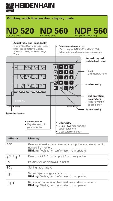
Actual value and input display<br />
(7-segment LED, 8 decades with<br />
sign); top to bottom: X axis,<br />
Y axis, ND 560 / NDP 560 only:<br />
Z axis<br />
REF 1 2<br />
<strong>HEIDENHAIN</strong><br />
in. SCL<br />
Indicator Meaning<br />
X<br />
Y<br />
Z<br />
1<br />
2<br />
• Select coordinate axis<br />
(Z axis only with ND 560 and NDP 560)<br />
Select axis-specific operating parameters<br />
7 8 9<br />
4<br />
1<br />
0<br />
CL SPEC<br />
FCT<br />
5<br />
2<br />
MOD<br />
6<br />
3<br />
ENT<br />
Clear entry<br />
CL plus two-digit number:<br />
select parameter<br />
Clear parameter entry<br />
Datum setting<br />
REF Reference mark crossed over – datum points are now stored in<br />
nonvolatile memory.<br />
Blinking: Waiting for confirmation from operator.<br />
1 / 2 Datum point 1 / Datum point 2 currently active<br />
in. Position values displayed in inches<br />
SCL Scaling factor active<br />
→<br />
→<br />
<strong>HEIDENHAIN</strong><br />
Working with the position display units<br />
ND 520 ND 560 NDP 560<br />
For two axes For three axes For panel mounting<br />
Status indicators<br />
←<br />
Select datum<br />
Page backward in<br />
parameter list<br />
Set workpiece edge as datum.<br />
Blinking: Waiting for confirmation from operator.<br />
Numeric keypad<br />
and decimal point<br />
Set centerline between two workpiece edges as datum.<br />
Blinking: Waiting for confirmation from operator.<br />
Sign<br />
Change parameter<br />
Confirm entry<br />
Call operating<br />
parameters<br />
Page forward in<br />
parameter list
The ND 520, ND 560 and NDP 560 are designed for use with <strong>HEIDENHAIN</strong> linear<br />
encoders with sinusoidal output signals.<br />
The linear encoders have one reference mark or several (preferably distance-coded)<br />
reference marks. When a reference mark is crossed over, a signal is generated which<br />
identifies that position as a reference point.<br />
After switch-on, crossing over the reference marks restores the relationship between<br />
axis slide positions and display values last established by datum setting. With<br />
encoders which have distance-coded reference marks, this requires a traverse of no<br />
more than 20 mm.<br />
Switch-On<br />
Turn on the power<br />
➤ Switch on the display unit with the power switch on the rear panel.<br />
The display shows and REF blinks.<br />
Switch on reference mark evaluation<br />
➤ Press ENT.<br />
The display shows the value last assigned to the reference mark position.<br />
REF glows and the decimal point blinks.<br />
Cross over the reference mark in each axis<br />
➤ Move the axes one after the other until the display becomes active and the<br />
decimal point glows steadily.<br />
The display unit is now ready for operation.<br />
If you do not wish reference mark evaluation, press CL instead of ENT.<br />
Datum Setting<br />
The datum setting procedure assigns a specific axis<br />
position to the associated display value.<br />
You can set two separate datum points and switch<br />
from one to the other with the touch of a key. Use<br />
datum 2 when you want to display incremental<br />
dimensions.<br />
➤ Select the datum.<br />
➤ Select the coordinate axis in which the tool<br />
moves (for example, the X axis).<br />
➤ Touch the workpiece with the tool.<br />
➤ Enter the position of the tool center using the<br />
numeric keypad (for example, X = –5 [mm]). A<br />
minus sign cannot be entered until at least one<br />
digit is in the display.<br />
➤ Press ENT.<br />
This stores the value for the tool position.<br />
Follow same procedure for the other axes.<br />
Y<br />
Z<br />
Touching the workpiece<br />
X
Datum Setting with an Edge Finder<br />
The special functions of your display unit enable you to use a <strong>HEIDENHAIN</strong> KT edge<br />
finder to set a workpiece edge or the centerline between two workpiece edges as a<br />
datum. The position displays take into account the edge finder diameter which you<br />
entered in operating parameter P25.<br />
If you are using the NDP 560 (which has no edge finder input) or if you want to use<br />
the special functions with a tool, please see the instructions on the next page.<br />
Workpiece edge as datum<br />
➤ Select the datum.<br />
➤ Press the SPEC FCT key once.<br />
The indicator "Workpiece edge as datum" blinks.<br />
➤ Press ENT.<br />
The indicator glows steadily.<br />
Z<br />
➤ Select the coordinate axis in which the tool<br />
moves. The selected axis glows more brightly.<br />
Y<br />
➤ Probe the workpiece with the edge finder until<br />
the LEDs in the edge finder light up and the<br />
display shows the position of the workpiece edge.<br />
➤ Enter the new coordinate value for the probed<br />
X? X<br />
edge.<br />
➤ Press ENT.<br />
Workpiece edge as datum<br />
The workpiece edge is set to the new value, and the display shows the position of<br />
the edge finder relative to the new datum.<br />
This function ends automatically.<br />
Centerline between two workpiece edges as datum<br />
➤ Select the datum.<br />
➤ Press the SPEC FCT key twice. The indicator<br />
"Centerline as datum" blinks.<br />
➤ Press ENT.<br />
The indicator glows steadily.<br />
➤ Select the coordinate axis in which the tool<br />
moves. The selected axis glows more brightly.<br />
➤ Probe the workpiece with the edge finder until<br />
Z<br />
the LEDs in the edge finder light up and the<br />
decimal point blinks.<br />
➤ Probe the second workpiece edge with the edge<br />
Y<br />
finder until the LEDs in the edge finder light up<br />
and the display shows the position of the<br />
centerline. The decimal point glows steadily.<br />
X?<br />
X<br />
➤ Enter the new coordinate value for the<br />
centerline.<br />
➤ Press ENT.<br />
Centerline as datum<br />
The centerline is now set to the new value and the display shows the position of<br />
the edge finder relative to the new datum.<br />
This function ends automatically.<br />
To cancel the datum setting function:<br />
➤ When the indicator for the function is blinking: press CL<br />
➤ When the indicator for the function is glowing steadily: press SPEC FCT
Datum Setting with a Tool<br />
It is also possible to probe the workpiece with a tool instead of the edge finder. The<br />
functions for datum setting then differ as follows:<br />
The tool diameter is automatically taken into account during probing<br />
The position of the probed workpiece edge is not automatically stored.<br />
Tool diameter:<br />
➤ Enter the tool diameter in operating parameter P25.<br />
To store the position of the workpiece edge when the tool is touching the edge:<br />
➤ Press ENT.<br />
Working with Scaling Factors<br />
The ND 510 and the ND 550 can display the axis traverse lengthened or shortened<br />
by a scaling factor. You enter a scaling factor separately for each axis in the user<br />
parameter P12, then activate the scaling factor function with the user parameter<br />
P11. SCL is highlighted.<br />
Error Messages<br />
Message Cause and effect<br />
Traverse distance with datum setting function (SPEC FCT) is<br />
too short<br />
Incorrect input value<br />
Encoder signal too weak (encoder may be contaminated)<br />
Input frequency too high for encoder input<br />
(will occur for example when traverse speed too high)<br />
Encoder signal to strong<br />
Internal counter overflow<br />
Error while crossing over reference marks<br />
To clear the error message: Switch off the display unit.<br />
Should any of these error codes recur,<br />
contact your <strong>HEIDENHAIN</strong> service agency.<br />
Offset compensation values for encoder signals have been<br />
erased: contact your service agency.<br />
Compensation values for nonlinear axis error compensation have<br />
been erased<br />
Datums have been erased<br />
Erase the operating parameters.<br />
If all decimal points light up, the measured value is too large or too small.<br />
Set a new datum.<br />
To clear error message :<br />
When you have removed the cause of the error,<br />
➤ press CL.
Non-linear Error Compensation<br />
To work with the non-linear error compensation it is necessary to<br />
activate the function via the operating parameter P40.<br />
traverse the reference marks after switching on.<br />
enter the compensation values in the table.<br />
For every axis compensation values can be entered over 16 compensation points. To<br />
determine the compensation values with a comparator system from <strong>HEIDENHAIN</strong>,<br />
such as VM 101, you must select the REF display.<br />
Selecting the Compensation Value Table<br />
➤ Select the operating parameter P00 and enter the code number 105 296. Use<br />
the following keys for the entries:<br />
Key Function<br />
MOD Save input value and select next input parameter.<br />
1 / 2 Save input value and select preceding input value.<br />
SPEC FCT Select REF display.<br />
ENT Save entry.<br />
Exit compensation value table.<br />
CL Delete entry.<br />
Delete all compensation values.<br />
➤ Enter the parameters and compensation values as follows:<br />
Display Entry<br />
Enter the axis to be compensated, e.g. X.<br />
Enter the axis causing the error, e.g. X, i.e. X = F(X).<br />
Enter the datum on the axis causing the error.<br />
Enter the distance of the compensation points on the errorcausing<br />
axis, e.g. 14 (= 2 14 µm = 16.384 mm).<br />
Minimum input value: 10 (= 1.024 mm)<br />
Maximum input value: 23 (= 8388.608 mm)<br />
Select compensation point No. 1. The compensation point<br />
number can be seen while pressing the MOD key. After letting<br />
go of the MOD key the coordinates of the selected compensation<br />
point can be seen in the upper line. Enter the compensation value<br />
in the lower line.<br />
Enter all following compensation points.<br />
Delete all compensation values:<br />
Display Entry<br />
Press key CL.<br />
Press key ENT. Compensation values are deleted.
Operating Parameters<br />
User User Parameters<br />
Parameters<br />
User parameters are operating parameters that can be changed without without entering<br />
the codes: P00 to P25<br />
Axis assignment<br />
Axis-specific parameters (those requiring separate entries for each axis) have axis<br />
codes: 1 for the X axis, 2 for the Y axis, and 3 for the Z axis.<br />
The axis code is separated from the parameter number by a point.<br />
In the operating parameter list, these parameters are set off with a superscript " A" and<br />
the parameter for the X axis is given (e.g., ).<br />
You select axis-specific operating parameters with the orange axis keys.<br />
To access the operating parameters:<br />
➤ Press MOD<br />
To go directly to an operating parameter:<br />
➤ Press and hold CL and press the first digit of the parameter number<br />
➤ Release both keys and enter the second digit of the parameter number<br />
To page through the operating parameters:<br />
➤ Page forward: press MOD<br />
➤ Page backward: press 1 / 2<br />
Any changes made are automatically activated when you resume paging.<br />
To change a parameter setting:<br />
➤ Change the setting with the minus key, or<br />
➤ Enter the desired value directly, e.g. for P25<br />
To correct an entry:<br />
➤ Press CL<br />
To exit the operating parameters:<br />
➤ Press ENT<br />
This activates all changes you made.<br />
Operating Parameter List<br />
Parameter Meaning Function / Effect Setting<br />
Code Number 95148: protected operating parameter<br />
105296: select compensation value table<br />
Unit of Dimensions in mm<br />
measurement Dimensions in inch<br />
Radius-/diameter Radius<br />
display A Diameter<br />
Scaling factor Scaling factor active<br />
Scaling Scaling factor inactive<br />
Scaling factor A Enter a value for each axis separately<br />
0,1 ≤ P12 ≤ 9,999 999<br />
Tool diameter Enter the tool diameter<br />
Tool 0 ≤ P25 ≤ 199,999 [mm]
Operating Parameter List – cont'd.<br />
Parameter Meaning Function / Effect Setting<br />
Counting Normal (Direction: Positive)<br />
direction A Inverse (Direction: Negative)<br />
Signal period of the encoder [µm] A<br />
(Period:) 2, 4, 10, 20, 40, 100, 200, 12 800<br />
Subdivision of the encoder signals A (Subdivision:)<br />
128, 100, 80, 64, 50, 40, 20, 10, 5, 4, 2, 1, 0.8, 0.5, 0.4, 0.2, 0.1<br />
Select Error compensation not active<br />
error Linear error compensation active<br />
compensation Non-linear error compensation active<br />
1) Linear error compensation A<br />
Compensation – 99 999 < P41 < + 99 999 [µm/m]<br />
Reference One reference mark<br />
marks A Distance-coded with 500 • SP<br />
(SP =signal period)<br />
Distance-coded with 1000 • SP<br />
(e.g. for LS 303 C / LS 603 C)<br />
Distance-coded with 2000 • SP<br />
Distance-coded with 5000 • SP<br />
Encoder Monitoring off (Alarm Off)<br />
Encoder monitoring A Monitoring on (Alarm On)<br />
Axis display A Display measured position<br />
(Axis) Do not display measured position /<br />
no encoder<br />
Function of the Reset to zero with CL<br />
CL key No reset to zero with CL<br />
1) Entry value for P41<br />
Example: Displayed measuring length: Ld = 620.000 mm<br />
Actual length (as determined with a comparator system such as the VM 101 from<br />
<strong>HEIDENHAIN</strong>): La = 619.876 mm<br />
Length difference: ∆L = La – Ld = –124 µm<br />
Compensation factor: k = ∆L / Ld = –124 µm / 0.62 m = –200 [µm/m]<br />
Display step, signal period and subdivision for linear encoders<br />
Display step P31: Signal period [µm]<br />
2 2 4 4 10 10 20 20 20 40 40 100 100 200 200 12 12 800<br />
800<br />
[mm] [inches] P32: Subdivision<br />
0.000 02 0.000 001 100 – – – – – – –<br />
0.000 05 0.000 002 40 80 – – – – – –<br />
0.000 1 0.000 005 20 40 100 – – – – –<br />
0.000 2 0.000 01 10 20 50 100 – – – –<br />
0.000 5 0.000 02 4 8 20 40 80 – – –<br />
0.001 0.000 05 2 4 10 20 40 100 – –<br />
0.002 0.000 1 1 2 5 10 20 50 100 –<br />
0.005 0.000 2 0.4 0.8 2 4 8 20 40 –<br />
0.01 0.000 5 0.2 0.4 1 2 4 10 20 –<br />
0.02 0.001 – – 0.5 1 2 5 10 –<br />
0.05 0.002 – – 0.2 0.4 0.8 2 4 –<br />
0.1 0.005 – – 0.1 0.2 0.4 1 2 128<br />
0.2 0.01 – – – – – – – 64
Parameter Settings for <strong>HEIDENHAIN</strong> Linear Encoders<br />
Model and signal<br />
period [µm]<br />
Reference<br />
marks<br />
P43<br />
Display step<br />
(unit: P01)<br />
mm inches<br />
Subdivision,<br />
P32<br />
LIP 40x 2 one single 0.001 0.000 05 2<br />
0.000 5 0.000 02 4<br />
0.000 2 0.000 01 10<br />
0.000 1 0.000 005 20<br />
0.000 05 0.000 002 40<br />
0.000 02 0.000 001 100<br />
LIP 101 A 4 one single 0.001 0.000 05 4<br />
LIP 101 R 0.000 5 0.000 02 8<br />
0.000 2 0.000 01 20<br />
0.000 1 0.000 005 40<br />
0.000 05 0.000 002 80<br />
LIF 101R 4 one single 0.001 0.000 05 4<br />
LIF 101 C dist. cod. 5000 0.000 5 0.000 02 8<br />
LIF 401 one single 0.000 2 0.000 01 20<br />
LIF 401 C dist. cod 5000 0.000 1 0.000 005 40<br />
LID xxx/LID xxx C 10 one/dist.cod. single/2000 0.001 0.000 05 10<br />
LS 103/LS 103 C 10 one/dist.cod. single/1000 0.000 5 0.000 02 20<br />
LS 405/LS 405 C 0.000 2 0.000 01 50<br />
ULS/10 0.000 1 0.000 005 100<br />
LS 303/LS 303 C 20 one/dist.cod. single/1000 0.01 0.000 5 2<br />
LS 603/LS 603 C 0.005 0.000 2 4<br />
LS 106/LS 106 C 20 one/dist.cod. single/1000 0.01 0.000 5 2<br />
LS 406/LS 406 C 0.005 0.000 2 4<br />
LS 706/LS 706 C 0.002 0.000 1 10<br />
ULS/20 0.001 0.000 05 20<br />
0.000 5 0.000 02 40<br />
LIDA 10x 40 one/dist.cod. single/2000 0.002 0.000 1 20<br />
LB 302 0.001 0.000 05 40<br />
0.000 5 0.000 02 80<br />
LIDA 2xx 100 one single 0.01 0.000 5 10<br />
LB 3xx 0.005 0.000 2 20<br />
LB 3xx C dist. cod. 1000 0.002 0.000 1 50<br />
0.001 0.000 05 100<br />
LIM 102 12800 one single 0.1 0.005 128<br />
Example: Linear encoder with signal period s = 20 µm<br />
Desired display step a = 0.005 mm<br />
Subdivision P32 = = 0.001 • s / a = 4<br />
Linear measurement with ballscrew and rotary encoder<br />
If you are measuring linear distance with a ballscrew and rotary encoder, calculate<br />
the signal period as follows:<br />
Signal period s = Screw pitch [mm] • 1000<br />
[µm]<br />
Line count
ND 520/ND560: Rear Panel<br />
Inputs for <strong>HEIDENHAIN</strong> linear encoders<br />
(ND 520: 2, ND 560: 3)<br />
with sinusoidal output signals<br />
(7µA pp to 16 µA pp),<br />
Connecting cable max. 30 m (98.5 ft),<br />
Input frequency max. 100 kHz<br />
Power switch<br />
Edge finder input<br />
X 10<br />
X 3<br />
X 2 X 1<br />
Interfaces X1, X2, X3 and X10 comply with the recommendations in<br />
EN 50 178 for separation from line power.<br />
NDP 560: Front and Rear Panel<br />
REF 1 2<br />
PGM<br />
XXXX<br />
X51<br />
L1 N<br />
in. SCL<br />
X<br />
Y<br />
Z<br />
1<br />
2<br />
7 8 9<br />
4<br />
1<br />
0<br />
CL SPEC<br />
FCT<br />
5<br />
2<br />
MOD<br />
6<br />
3<br />
ENT<br />
<strong>HEIDENHAIN</strong><br />
X1<br />
X2<br />
X3<br />
Ground terminal<br />
Front panel dimensions [mm]<br />
259+0.5 x 198.5+0.5<br />
Mounting depth min. 140 mm<br />
Inputs X1 to X3 for <strong>HEIDENHAIN</strong><br />
linear encoders with sinusoidal<br />
output signals (see above)<br />
Ground terminal<br />
Power connection
ND 520/ND 560: Installation<br />
The display unit can be mounted on a flat<br />
surface or on the tilting base from<br />
<strong>HEIDENHAIN</strong> (Id.-Nr. 281 619 01) with M4<br />
screws.<br />
Power Supply and Connection<br />
288 391 23 · SW 246 180 05 · 3 · 10/97 · H · Printed in Germany · Subject to change without notice<br />
93+2<br />
3.66+.08"<br />
20<br />
.79"<br />
0<br />
21±0.2<br />
1±.008"<br />
43.3<br />
1.704"<br />
92<br />
3.622"<br />
M4<br />
209±0.2<br />
8.228±.008"<br />
230±0.2<br />
9.055±.008"<br />
Danger of electrical shock!<br />
Unplug the power cable before opening the housing.<br />
Connect a protective ground. This connection should never be interrupted.<br />
Danger to internal components!<br />
Do not engage or disengage any connections while the unit is under power.<br />
Use only original replacement fuses.<br />
Primary-clocked power supply.<br />
Voltage range 100 V to 240 V (–15% to +10 %), Frequency 48 Hz to 62 Hz,<br />
Power consumption ND 520: 9 W, ND 560 and NDP 560: 12 W,<br />
Line fuse F 1 A (in unit).<br />
Minimum cross-section of power cable: 0.75 mm 2<br />
To increase the noise immunity, connect the ground terminal on the rear panel<br />
to the central ground point of the machine. (Minimum cross-section 6 mm 2 )<br />
Power connection – ND 520 and ND 560<br />
The ND 520 and ND 560 have a socket on the rear panel for the power cable.<br />
Power connection – NDP 560<br />
The NDP 560 has a terminal (X 51) on the rear<br />
panel for the power connection.<br />
Ambient Conditions<br />
Temperature range Operation: 0°C to +45°C (32°F to +113°F)<br />
Storage: –30°C to +70°C (–22°F to +158°F)<br />
Rel. humidity Annual average: < 75%; maximum: < 90%<br />
Weight 2.5 kg<br />
<strong>DR</strong>. <strong>JOHANNES</strong> <strong>HEIDENHAIN</strong> <strong>GmbH</strong><br />
Dr.-Johannes-Heidenhain-Straße 5<br />
D-83301 Traunreut, Deutschland<br />
(0 86 69) 31-0 . 56 831<br />
FAX (0 86 69) 50 61<br />
FAX<br />
Service (0 86 69) 31-12 72<br />
TNC-Service (0 86 69) 31-14 46<br />
(0 86 69) 98 99<br />
X 51<br />
L1 N<br />
56±0.2<br />
2.204±.008"<br />
29+0.5<br />
1.14+.02"


