VERY IMPORTANT As the booklet is constantly re-edited, this one ...
VERY IMPORTANT As the booklet is constantly re-edited, this one ...
VERY IMPORTANT As the booklet is constantly re-edited, this one ...

Create successful ePaper yourself
Turn your PDF publications into a flip-book with our unique Google optimized e-Paper software.
Engine<br />
families<br />
Engine<br />
types<br />
C5<br />
C8<br />
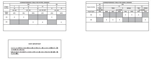
CORRESPONDENCE TABLE FOR PETROL ENGINES<br />
CORRESPONDENCE TABLE FOR DIESEL ENGINES<br />
EW ES<br />
DV<br />
DW<br />
7<br />
J4 A<br />
10<br />
J4<br />
12<br />
A<br />
9<br />
J4<br />
Engine families<br />
6<br />
TED4<br />
TED4<br />
10<br />
BTED4 TED<br />
12<br />
ATED4<br />
1.8i 16V 2.0i 16V 2.2i 16V HPi<br />
3.0i 24V<br />
Engine types<br />
1,6 16V HDi<br />
9HZ RHM RHT<br />
2,0 16VHDi<br />
RHW RHL RHR<br />
2,2 16VHDi<br />
4HX 4HW<br />
6FZ RFJ RFN 3FZ<br />
XFU<br />
XFW<br />
C5<br />
X<br />
X X<br />
X<br />
X X X<br />
X<br />
<strong>VERY</strong> <strong>IMPORTANT</strong><br />
<strong>As</strong> <strong>the</strong> <strong>booklet</strong> <strong>is</strong> <strong>constantly</strong> <strong>re</strong>-<strong>edited</strong>, th<strong>is</strong> <strong>one</strong> only covers vehicles for th<strong>is</strong><br />
particular model year.<br />
It <strong>is</strong> <strong>the</strong><strong>re</strong>fo<strong>re</strong> necessary toorder a new <strong>booklet</strong> each year and RETAIN THE<br />
OLD ONES.<br />
X<br />
X<br />
C8<br />
X X<br />
X X
AC/DTAV/PRME/MMCB/MMEC<br />
Méthodes Mécaniques<br />
© «The intellectual property rights <strong>re</strong>lating to <strong>the</strong> technical information contained in th<strong>is</strong> document belong<br />
exclusively to <strong>the</strong> manufactu<strong>re</strong>r. Reproduction, translation or d<strong>is</strong>tribution in whole or in part without prior<br />
written author<strong>is</strong>ation from <strong>the</strong> manufactu<strong>re</strong>r <strong>is</strong> forbidden».<br />
PRIVATE CARS<br />
2005<br />
PRIVATE CARS<br />
CITROËN C5 - CITROËN C8<br />
«The technical information contained in th<strong>is</strong> document <strong>is</strong> intended for <strong>the</strong> exclusive use of <strong>the</strong> trained personnel<br />
of <strong>the</strong> motor vehicle <strong>re</strong>pair trade. In some instances, th<strong>is</strong> information could concern <strong>the</strong> security and safety of<br />
<strong>the</strong> vehicle. The information <strong>is</strong> to be used by <strong>the</strong> professional vehicle <strong>re</strong>pai<strong>re</strong>rs for whom it <strong>is</strong> intended and <strong>the</strong>y<br />
al<strong>one</strong> would assume full <strong>re</strong>sponsibility to <strong>the</strong> exclusion of that of <strong>the</strong> manufactu<strong>re</strong>r».<br />
«The technical information appearing in th<strong>is</strong> brochu<strong>re</strong> <strong>is</strong> subject to updating as <strong>the</strong> character<strong>is</strong>tics of each<br />
model in <strong>the</strong> range evolve. Motor vehicle <strong>re</strong>pai<strong>re</strong>rs a<strong>re</strong> invited to contact <strong>the</strong> CITROËN network periodically for<br />
fur<strong>the</strong>r information and to obtain any possible updates».<br />
CAR 000.020<br />
22000055
PRESENTATION<br />
THIS HANDBOOK summar<strong>is</strong>es <strong>the</strong> specifications, adjustments, checks and special featu<strong>re</strong>s of CITROËN private vehicles, not including UTILITY<br />
vehicles for which <strong>the</strong><strong>re</strong> ex<strong>is</strong>ts a separate handbook.<br />
The handbook <strong>is</strong> divided into groups <strong>re</strong>p<strong>re</strong>senting <strong>the</strong> main functions:<br />
GENERAL - ENGINE - INJECTION - IGNITION - CLUTCH, GEARBOX, DRIVESHAFTS - AXLES, SUSPENSION, STEERING - BRAKES -<br />
HYDRAULICS - AIR CONDITIONING.<br />
In each section, <strong>the</strong> vehicles a<strong>re</strong> dealt with in <strong>the</strong> following order: C5 - C8 and all models whe<strong>re</strong> applicable.<br />
The information given in th<strong>is</strong> handbook <strong>is</strong> based on vehicles marketed in EUROPE.
<strong>IMPORTANT</strong><br />
If you find that th<strong>is</strong> handbook does not always meet your <strong>re</strong>qui<strong>re</strong>ments, we invite you to send us your suggestions which we will take into account<br />
when p<strong>re</strong>paring futu<strong>re</strong> publications. For example:<br />
Please send your comments and suggestions to:<br />
- INSUFFICIENT INFORMATION.<br />
- SUPERFLUOUS INFORMATION.<br />
- NEED FOR MORE DETAILS.<br />
CITROEN U.K. Ltd.<br />
221, Bath Road,<br />
SLOUGH,<br />
SL1 4BA.<br />
U.K.
GENERAL<br />
Vehicle C5 1 - 2<br />
CONTENTS<br />
Checking <strong>the</strong> turbo p<strong>re</strong>ssu<strong>re</strong>:<br />
C5 (DV6TED4)<br />
194<br />
identification<br />
Capacities<br />
Lubricants<br />
ENGINE<br />
C8<br />
C5<br />
C8<br />
3 - 4<br />
6 - 7<br />
8<br />
9 - 31<br />
Checking <strong>the</strong> turbo p<strong>re</strong>ssu<strong>re</strong>:<br />
C5 (DW10BTED4)<br />
Checking <strong>the</strong> turbo p<strong>re</strong>ssu<strong>re</strong>:<br />
C5 (DW12TED)<br />
Checking <strong>the</strong> air supply circuit:<br />
C5 (DV6TED4)<br />
195<br />
196 - 197<br />
198<br />
Specifications<br />
Comp<strong>re</strong>ssion ratios<br />
32 - 33<br />
34<br />
Checking <strong>the</strong> air supply circuit:<br />
C5 (DW10BTED4)<br />
199 - 200<br />
Tightening torques: engines all types<br />
Cylinder head tightening: all types<br />
35 - 87<br />
88 - 91<br />
Checking <strong>the</strong> air supply circuit:<br />
C5 (DW12TED)<br />
201 - 202<br />
Auxiliary drive belt<br />
Checking and setting <strong>the</strong> valve timing<br />
Checking <strong>the</strong> oil p<strong>re</strong>ssu<strong>re</strong><br />
93<br />
109<br />
188 - 189<br />
Checking <strong>the</strong> exhaust gas <strong>re</strong>cycling<br />
circuit: (DV6TED4)<br />
Checking <strong>the</strong> exhaust gas <strong>re</strong>cycling<br />
circuit: (DW12TED)<br />
203<br />
204 - 205<br />
Valve clearances 190 IGNITION<br />
INJECTION<br />
Sparking plugs 206<br />
Checking <strong>the</strong> low p<strong>re</strong>ssu<strong>re</strong> fuel<br />
supply circuit: C5 (DW10BTED4)<br />
Checking <strong>the</strong> low p<strong>re</strong>ssu<strong>re</strong> fuel<br />
supply circuit : C5 (DW12TED)<br />
190<br />
192 - 193<br />
CLUTCH - GEARBOX - TRANSMISSION<br />
Speedometer<br />
Clutch specifications: C5<br />
207<br />
208<br />
Clutch specifications: C8 209<br />
Manual/automatic gearbox:<br />
all types<br />
201 - 211<br />
Tightening torques: clutch 212 - 214<br />
Hydraulic clutch control 215 - 216<br />
Tightening torques<br />
manual gearbox: all types<br />
217 - 223<br />
Checks and adjustments:<br />
manual gearbox all types<br />
224 - 232<br />
Recommendations/p<strong>re</strong>cautions:<br />
AL4 automatic gearbox<br />
233 - 235<br />
Tightening torques: AL4 236 - 238<br />
AL4 gearbox controls 239 - 240<br />
AL4 gearbox controls 241<br />
Recommendations/p<strong>re</strong>cautions:<br />
4 HP 20 automatic gearbox<br />
242<br />
Tightening torques:<br />
4HP 20 gearbox<br />
243 - 244<br />
4HP 20 gearbox controls 245
CLUTCH - GEARBOX - TRANSMISSION<br />
4 HP 20 Shift lock: C5 246<br />
Checks and adjustments:<br />
4 HP 20: C5<br />
247<br />
4 HP 20 Shift lock: C8 248<br />
Checks and adjustments:<br />
4 HP 20: C8<br />
249<br />
Recommendations/p<strong>re</strong>cautions:<br />
AM6 gearbox: C5<br />
250<br />
Tightening torques: AM6 gearbox 251 - 252<br />
AM6 gearbox controls 253<br />
AM6 Shift lock: C5 254<br />
Driveshafts 255<br />
AXLES - SUSPENSION - STEERING<br />
Axle geometry: C5 all types<br />
except CARLSSON<br />
256 - 257<br />
Axle geometry: C5 CARLSSON 258 - 259<br />
Checking/adjusting vehicle height:<br />
C5<br />
260 - 264<br />
Tightening torques: front axle: C5 265 - 266<br />
CONTENTS<br />
Tightening torques: <strong>re</strong>ar axle: C5<br />
Tightening torques:<br />
power steering: C5<br />
267 - 268<br />
269 - 271<br />
Draining, filling, bleeding<br />
<strong>the</strong> braking circuit : C8<br />
HYDRAULICS<br />
297 - 299<br />
Axle geometry: C8<br />
Adjusting <strong>the</strong> rolling axles: C8<br />
Tightening torques: front axle: C8<br />
Tightening torques: <strong>re</strong>ar axle: C8<br />
Tightening torques:<br />
power steering: C8<br />
BRAKES<br />
Brake specifications: C5<br />
272 - 276<br />
277<br />
278 - 279<br />
280<br />
281<br />
282 - 284<br />
Safety <strong>re</strong>qui<strong>re</strong>ments: Hydractive<br />
3 hydraulic suspension<br />
Specification / identification:<br />
suspension sphe<strong>re</strong>s<br />
Hydraulic specifications<br />
Dep<strong>re</strong>ssur<strong>is</strong>ing <strong>the</strong> hydraulic<br />
suspension circuit<br />
Draining and filling <strong>the</strong> hydraulic<br />
suspension and steering circuit<br />
300 - 301<br />
302 - 306<br />
307 - 310<br />
311 - 313<br />
314 - 320<br />
Brake tightening torques: C5 285 - 286 Checking/adjusting vehicle height 321<br />
Checking/adjusting<br />
vacuum pump: C5<br />
287 AIR CONDITIONING<br />
R134.a: quantities 322<br />
Adjusting <strong>the</strong> handbrake: C5 288 - 289 Pollen filter 324 - 325<br />
Draining, filling, bleeding<br />
<strong>the</strong> braking circuit: C5<br />
290 - 292<br />
Filtering and drying cartridge<br />
Comp<strong>re</strong>ssor lubricant<br />
326 - 331<br />
332 - 333<br />
Brake specifications: C8 293<br />
Checking <strong>the</strong> efficiency of <strong>the</strong> circuit 334 - 343<br />
Brake tightening torques: C8 294 Air conditioning circuit: C5 344 - 348<br />
Adjusting <strong>the</strong> handbrake: C8 295 - 296 Air conditioning circuit: C8 349 - 351
E1APO8RD<br />
IDENTIFICATION OF VEHICLES<br />
1<br />
A- Chass<strong>is</strong> stamp<br />
(cold stamp on bodywork).<br />
B - Manufactu<strong>re</strong>r's data plate<br />
(under <strong>the</strong> <strong>re</strong>ar bench seat).<br />
C - A-S/RP No. and RP paint code<br />
(label on front pillar close to driver's door).<br />
D - Inflation p<strong>re</strong>ssu<strong>re</strong>s and ty<strong>re</strong> <strong>re</strong>fe<strong>re</strong>nces<br />
(label on front pillar close to driver's door).<br />
E - Serial no. on bodywork.<br />
F - Gearbox <strong>re</strong>fe<strong>re</strong>nce - Factory serial no.<br />
G - Engine leg<strong>is</strong>lation type - Factory serial no.<br />
C5<br />
GENERAL GENERAL
GENERAL<br />
C5 IDENTIFICATION OF VEHICLES<br />
Structu<strong>re</strong><br />
D Family (1)<br />
DC<br />
RFNC/IF<br />
C<br />
RFN<br />
C<br />
Bodywork (2)<br />
Engine (3)<br />
Version (4)<br />
/IF Variant (5)<br />
D<br />
Family (1)<br />
C5<br />
Body shape (2)<br />
C 5-door saloon<br />
E Estate<br />
6FZ<br />
Engine (3)<br />
EW7J4 1.8i 16V<br />
RFJ EW10A 2.0i 16V<br />
XFU ES9A 3.0i 24S<br />
9HZ DV6TED4 1.6i 16 HDi<br />
RHL<br />
RHR<br />
DW10BTED4 2.0i 16V HDi<br />
4HX DW12TED4 2.2 16V HDi<br />
Type approval<br />
Version (4)<br />
Depollution levels<br />
L3<br />
L4 Euro IV<br />
Manual 5-speed gearbox A B C P V 5 8 1<br />
Manual 4-speed gearbox E F R W 6 9 2<br />
Manual 6-speed gearbox ts G H S X 3<br />
Automatic 6-speed gearbox D J N U<br />
Axle and/or gearbox gears K L T Y 7 0 4<br />
O<strong>the</strong>r possible combinations M<br />
No gearbox Z<br />
US<br />
W3 83/87<br />
O<strong>the</strong>r<br />
K<br />
K’<br />
Alcohol<br />
L3/L4 Euro IV<br />
Variants (5)<br />
Ent<strong>re</strong>pr<strong>is</strong>e convertible T<br />
Integral alternator-starter (ADIN) AD<br />
Without FAP SF<br />
F<strong>is</strong>cal incentives IF<br />
Piloted manual gearbox P<br />
Downgraded depollution D<br />
LPG dual fuel GL<br />
STT2 (stop and start) S<br />
2
E1AP0A2D<br />
IDENTIFICATION OF VEHICLES<br />
3<br />
A- Chass<strong>is</strong> stamp<br />
(cold stamp on bodywork).<br />
B - Manufactu<strong>re</strong>r's data plate<br />
(under RH cent<strong>re</strong> pillar).<br />
C - A-S / RP No. and RP paint code<br />
(label on front pillar).<br />
D - Inflation p<strong>re</strong>ssu<strong>re</strong>s and ty<strong>re</strong> <strong>re</strong>fe<strong>re</strong>nces<br />
(label on front pillar).<br />
E - Gearbox <strong>re</strong>fe<strong>re</strong>nce - Factory serial no.<br />
F - Engine leg<strong>is</strong>lation type - Factory serial no.<br />
C8<br />
GENERAL GENERAL
GENERAL<br />
C8 IDENTIFICATION OF VEHICLES<br />
Structu<strong>re</strong><br />
E Family (1)<br />
EA<br />
XFWF/IF<br />
A<br />
XFW<br />
F<br />
Bodywork (2)<br />
Engine (3)<br />
Version (4)<br />
/IF Variant (5)<br />
E<br />
Family (1)<br />
C8<br />
Body shape (2)<br />
A Monospace 7 seats maximum<br />
B Monospace 8 seats maximum<br />
RFN<br />
Engine (3)<br />
EW10J4 2.0i 16V<br />
3FZ EW12J4 2.2i 16V Hpi<br />
XFW<br />
RHM<br />
ES9J4 3.0i 24S<br />
RHT<br />
RHW<br />
DW10TED4 2.0i 16V HDi<br />
4HW DW12ATED4 2.2i 16V HDi<br />
Type approval<br />
Version (4)<br />
Depollution levels<br />
L3<br />
L4 Euro IV<br />
Manual 5-speed gearbox A B C P V 5 8 1<br />
Manual 4-speed gearbox E F R W 6 9 2<br />
Manual 6-speed gearbox ts G H S X 3<br />
Automatic 6-speed gearbox D J N U<br />
Axle and/or gearbox gears K L T Y 7 0 4<br />
O<strong>the</strong>r possible combinations M<br />
No gearbox Z<br />
US<br />
W3 83/87<br />
O<strong>the</strong>r<br />
K<br />
K’<br />
Alcohol<br />
L3/L4 Euro IV<br />
Variants (5)<br />
Ent<strong>re</strong>pr<strong>is</strong>e convertible T<br />
Integral alternator-starter (ADIN) AD<br />
Without FAP SF<br />
F<strong>is</strong>cal incentives IF<br />
Piloted manual gearbox P<br />
Downgraded depollution D<br />
LPG dual fuel GL<br />
STT2 (stop and start) S<br />
4
CAPACITIES (in lit<strong>re</strong>s)<br />
Draining methods<br />
Oil capacities a<strong>re</strong> defined according to <strong>the</strong> following methods<br />
Draining of <strong>the</strong> engine lubrication system by GRAVITY<br />
Draining of <strong>the</strong> engine lubrication system by SUCTION<br />
Place <strong>the</strong> vehicle on horizontal ground (in <strong>the</strong> high position if<br />
hydropneumatic suspension).<br />
Place <strong>the</strong> vehicle on horizontal ground (in <strong>the</strong> high position if<br />
hydropneumatic suspension).<br />
The engine should be hot (oil temperatu<strong>re</strong> 80°C).<br />
The engine should be hot (oil temperatu<strong>re</strong> 80°C).<br />
Drain <strong>the</strong> sump by gravity.<br />
Remove <strong>the</strong> oil by suction through <strong>the</strong> dipstick tube.<br />
Remove <strong>the</strong> oil filter cartridge (time for draining and drip-drip = 15<br />
Remove <strong>the</strong> oil filter cartridge.<br />
minutes approx.).<br />
Maintain <strong>the</strong> suction of oil in <strong>the</strong> sump (15 minutes approx.).<br />
Refit <strong>the</strong> cap with a new seal.<br />
Refit a new oil filter cartridge.<br />
Refit a new oil filter cartridge.<br />
Refill <strong>the</strong> engine with oil (see table for oil capacity).<br />
Refill <strong>the</strong> engine with oil (see table for oil capacity).<br />
Start <strong>the</strong> engine to fill <strong>the</strong> oil filter cartridge.<br />
Start <strong>the</strong> engine to fill <strong>the</strong> oil filter cartridge.<br />
Stop <strong>the</strong> engine (allow to stabil<strong>is</strong>e for 5 minutes).<br />
Stop <strong>the</strong> engine (allow to stabil<strong>is</strong>e for 5 minutes).<br />
WARNING: Remove <strong>the</strong> suction container befo<strong>re</strong> starting <strong>the</strong> engine.<br />
ESSENTIAL: Systematically check <strong>the</strong> oil level using <strong>the</strong> oil dipstick.<br />
5<br />
GENERAL GENERAL
GENERAL<br />
1.8i 16V<br />
CAPACITIES (in lit<strong>re</strong>s)<br />
C5<br />
Engine type 6FZ RFJ XFU<br />
Engine with filter change 4,25 5 5,25<br />
Between Min. and Max. 1,7 2<br />
5-speed gearbox 1,8 1,8 1,8<br />
Automatic gearbox 6 7<br />
After oil change<br />
Braking circuit<br />
3 4<br />
Hydraulic circuit 4,3<br />
Cooling system 8,8 14<br />
Fuel tank capacity 65<br />
IMPERATIVE: Systematically check <strong>the</strong> oil level using <strong>the</strong> oil dipstick.<br />
6<br />
Petrol<br />
2.0i 16V<br />
AUTO.<br />
3.0i 24S<br />
AUTO.
1.6 16V HDi<br />
CAPACITIES (in lit<strong>re</strong>s)<br />
C5<br />
2.0 16V HDi<br />
Engine type 9HZ RHL RHR 4HX<br />
Engine with filter change 3,75 5,25 4,75<br />
Between Min. and Max. 1,55 1,9 1,5<br />
5-speed gearbox 1,8 1,8<br />
Automatic gearbox 8,3<br />
After oil change<br />
Braking circuit<br />
5,3<br />
Hydraulic circuit 4,3<br />
Cooling system 10,5 11,7 (with additional heating)<br />
Fuel tank capacity 65<br />
IMPERATIVE: Systematically check <strong>the</strong> oil level using <strong>the</strong> oil dipstick.<br />
7<br />
Diesel<br />
2.2 16V HDi<br />
AUTO.<br />
GENERAL GENERAL
GENERAL<br />
Petrol<br />
CAPACITIES (in lit<strong>re</strong>s)<br />
C8<br />
2.0i 16v 2.2i 16V 3.0i 24V<br />
AUTO.<br />
Engine type RFN 3FZ XFW RHM RHT RHW 4HW<br />
Engine with filter change 4,25 5,25 4,75 4,75<br />
Between Min. and Max. 1,7 2 1,9 1,5<br />
5-speed gearbox 1,8 2 2<br />
Automatic gearbox 8,3 6<br />
After oil change 5,3 3<br />
Hydraulic circuit 0,66<br />
Cooling system 7 7,2 10,5 10 11,3<br />
Fuel tank capacity 80<br />
8<br />
2.0 16V HDi<br />
Diesel<br />
2.2 16V HDi<br />
AUTO.
EVOLUTIONS (YEAR 2004).<br />
CITROËN C4<br />
Petrol engine versions except 2.0 i 16V 180 hp (132 kW):<br />
- Normal maintenance interval: 30 000 km (20 000 miles).<br />
- Seve<strong>re</strong> maintenance interval: 20 000 km (12 000 miles).<br />
Petrol engine version 2.0L i 16V 180 hp (132 kW):<br />
- Normal maintenance interval: 20 000 km (12 500 miles).<br />
- Seve<strong>re</strong> maintenance interval: 15 000 km (10 000 miles).<br />
Diesel engine versions.<br />
WARNING: Vehicles HDi FAP (*) do not accept <strong>the</strong> energy economy<br />
oil TOTAL ACTIVA FUTUR 9000 5W30 for France, TOTAL QUARTZ<br />
FUTURE 9000 5W30 outside France .<br />
DV6 engines:<br />
- Normal maintenance interval: 20 000 km (12 500 miles).<br />
- Seve<strong>re</strong> maintenance interval: 15 000 km (10 000 miles).<br />
DW engines:<br />
- Normal maintenance interval: 30 000 km (20 000 miles).<br />
- Seve<strong>re</strong> maintenance interval: 20 000 km (12 000 miles).<br />
LUBRICANTS - TOTAL <strong>re</strong>commended oils<br />
9<br />
New Look CITROËN C5<br />
Petrol engine versions:<br />
- Normal maintenance interval: 30 000 km (20 000 miles).<br />
- Seve<strong>re</strong> maintenance interval: 20 000 km (12 000 miles).<br />
Diesel engine versions.<br />
WARNING: Vehicles HDi FAP (*) do not accept <strong>the</strong> energy economy<br />
oil TOTAL ACTIVA FUTUR 9000 5W30 for France, TOTAL QUARTZ<br />
FUTURE 9000 5W30 outside France.<br />
DV6 engines:<br />
- Normal maintenance interval: 20 000 km (12 500 miles).<br />
- Seve<strong>re</strong> maintenance interval: 15 000 km (10 000 miles).<br />
DW engines :<br />
- Normal maintenance interval: 30 000 km (20 000 miles).<br />
- Seve<strong>re</strong> maintenance interval: 20 000 km (12 000 miles).<br />
ESSENTIAL: For all vehicles with a 30 000 km (20 000 miles) maintenance<br />
interval, use exclusively TOTAL ACTIVA/QUARTZ 7000 or<br />
9000 or any o<strong>the</strong>r oils offering identical specifications to <strong>the</strong>se.<br />
These oils offer specifications that a<strong>re</strong> superior to those defined by<br />
norms ACEA A3 OR API SJ/CF.<br />
Failing th<strong>is</strong>, it <strong>is</strong> essential to adhe<strong>re</strong> to <strong>the</strong> maintenance programmes<br />
covering seve<strong>re</strong> operating conditions.<br />
GENERAL GENERAL
GENERAL<br />
Use of oil grade 10W40.<br />
It <strong>is</strong> possible to use <strong>the</strong> semi-syn<strong>the</strong>tic oil 7000 10W40 on HDi and HDi<br />
FAP vehicles.<br />
WARNING: To avoid difficulties when starting from cold (< 20°C), use<br />
5W40 oil.<br />
For mo<strong>re</strong> details, see <strong>the</strong> oil usage table (paragraph 3.3).<br />
Commercial description for energy economy oil.<br />
TOTAL ACTIVA FUTUR 9000 5W30 (France only).<br />
TOTAL QUARTZ FUTUR 9000 5W30 (except France).<br />
The exclusions for use of th<strong>is</strong> oil a<strong>re</strong> <strong>the</strong> following:<br />
- XSARA VTS 2.0 16V (XU10J4RS).<br />
- JUMPER/RELAY 2.8 HDi and 2.8 TDi (SOFIM engine).<br />
- HDi FAP vehicles.<br />
- CITROËN C3 HDi 16V (DV4TED4).<br />
- CITROËN C8 2.2i (EW12J4).<br />
- CITROËN C4 and C5 2.0i (EW10A).<br />
- CITROËN C4 (EW10J4S).<br />
Engine oil norms.<br />
Cur<strong>re</strong>nt norms.<br />
The classification of <strong>the</strong>se engine oils <strong>is</strong> establ<strong>is</strong>hed by <strong>the</strong> following<br />
<strong>re</strong>cogn<strong>is</strong>ed organ<strong>is</strong>ations:<br />
- S.A.E : Society of Automotive Engineers.<br />
- API : American Petroleum Institute.<br />
- ACEA : <strong>As</strong>sociation des Constructeurs Européens d'Automobiles.<br />
LUBRICANTS - TOTAL <strong>re</strong>commended oils<br />
S.A.E. Norms - Table for selection of engine oil grade.<br />
Selection of engine oil grades <strong>re</strong>commended for climatic conditions in<br />
countries of d<strong>is</strong>tribution (see table, paragraph 3.3).<br />
Evolution of <strong>the</strong> norms to 01/01/2003.<br />
ACEA 2003 norms.<br />
The meaning of <strong>the</strong> first letter has not changed, it still cor<strong>re</strong>sponds<br />
to <strong>the</strong> type of engine:<br />
- A: petrol and dual fuel petrol / LPG engines.<br />
- B: diesel engines.<br />
The figu<strong>re</strong> following <strong>the</strong> first letter cor<strong>re</strong>sponds to <strong>the</strong> type of oil:<br />
- 3: high performance oils.<br />
- 4: oils specifically for di<strong>re</strong>ct injection diesel engines.<br />
- 5: very high performance oils permitting lower fuel consumption, specific to<br />
di<strong>re</strong>ct injection diesel engines.<br />
Example:<br />
- ACEA A3: high performance oils specifically for petrol and dual fuel petrol/<br />
LPG engines.<br />
- ACEA A/B: blended oils giving very high performance for all engines, also<br />
permitting better fuel economy, specifically for di<strong>re</strong>ct injection diesel engines.<br />
NOTE: From 01/01/2003 <strong>the</strong><strong>re</strong> <strong>is</strong> no longer any <strong>re</strong>fe<strong>re</strong>nce to <strong>the</strong> year of<br />
c<strong>re</strong>ation of <strong>the</strong> norm (example : ACEA A3/B3 98 becomes ACEA A3/B3).<br />
10
API Norms:<br />
The meaning of <strong>the</strong> first letter has not changed, it still cor<strong>re</strong>sponds to <strong>the</strong><br />
type of engine:<br />
- S: petrol and dual fuel petrol / LPG engines.<br />
- C: diesel engines.<br />
The second letter cor<strong>re</strong>sponds to <strong>the</strong> deg<strong>re</strong>e of evolution of <strong>the</strong> oil<br />
(ascending order).<br />
Example: Norm SL <strong>is</strong> mo<strong>re</strong> seve<strong>re</strong> than norm SJ, cor<strong>re</strong>sponding to<br />
a higher level of performance.<br />
Recommendations.<br />
ESSENTIAL: To p<strong>re</strong>serve engine performances, all engines fitted in<br />
CITROËN vehicles must be lubricated with high quality oils (syn<strong>the</strong>tic<br />
or semi-syn<strong>the</strong>tic).<br />
CITROËN engines a<strong>re</strong> lubricated at <strong>the</strong> factory with TOTAL oil of grade<br />
S.A.E 5W-30.<br />
TOTAL oil of grade S.A.E 5W-30 allows improved fuel economies<br />
(approx 2.5%).<br />
The oil 5W30 <strong>is</strong> used only for <strong>the</strong> following engines (year 2004):<br />
- XU10 J4RS : XSARA VTS 2.0i 16V (3-door).<br />
- SOFIM : JUMPER / RELAY 2.8 TDi and 2.8 HDi.<br />
- HDi : With particle filter (FAP).<br />
- DV4 TED4 : CITROËN C3 1.4 16V HDi.<br />
- EW 12J4 : CITROËN C8 2.2i.<br />
- EW 10A : CITROËN C4 and C5 2.0i.<br />
- EW10J4S engine : CITROËN C4.<br />
LUBRICANTS - TOTAL <strong>re</strong>commended oils<br />
WARNING: CITROËN engines prior to model year 2000 do not have<br />
to be lubricated with oils adhering to <strong>the</strong> norms:<br />
- ACEA AI-98 and API SJ/CF EC or cur<strong>re</strong>nt norms ACEA A5/B5.<br />
Denomination of TOTAL oils according to country of marketing:<br />
- TOTAL ACTIVA (France only).<br />
- TOTAL QUARTZ (outside France).<br />
Summary.<br />
Norms to be <strong>re</strong>spected for engine oils (year 2004).<br />
Year Engine types concerned ACEA API<br />
Norms Norms<br />
11<br />
2003<br />
Petrol and LPG dual fuel engines<br />
Diesel engines<br />
A3 or A5<br />
(*)<br />
B3, B4<br />
or B5 (*)<br />
SJ or SL<br />
(*) It <strong>is</strong> essential not to use engine oils <strong>re</strong>specting <strong>the</strong>se norms for<br />
XU10J4RS, SOFIM 2.8 TDi and SOFIM 2.8 HDi engines, HDi engines<br />
with particle filter EW10A, EW12J4, DV4TED4.<br />
CF<br />
GENERAL GENERAL
GENERAL<br />
Classes and grades of TOTAL <strong>re</strong>commended engine oils.<br />
The oils d<strong>is</strong>tributed in each country a<strong>re</strong> suited to <strong>the</strong> local climatic<br />
conditions.<br />
Blended oils for all engines (petrol, diesel and dual fuel<br />
petrol/LPG):<br />
S.A.E. ACEA API<br />
norms norms norms<br />
TOTAL ACTIVA 9000 A3/B3/<br />
5W40<br />
TOTAL QUARTZ 9000<br />
TOTAL ACTIVA FUTUR 9000 (*)<br />
TOTAL QUARTZ FUTUR 9000 (*)<br />
5W30 A5/B5<br />
SL/CF<br />
TOTAL ACTIVRAC 10W40 A3/B3<br />
(*) Blended oils for all engines giving fuel economy.<br />
Oils for petrol, diesel and dual fuel petrol/LPG engines:<br />
S.A.E.<br />
norms<br />
ACEA<br />
norms<br />
API<br />
norms<br />
TOTAL ACTIVA 7000<br />
TOTAL QUARTZ 7000<br />
10W40<br />
TOTAL QUARTZ 9000 0W40 A3 SL<br />
TOTAL ACTIVA 7000<br />
TOTAL QUARTZ 7000<br />
15W50<br />
LUBRICANTS - TOTAL <strong>re</strong>commended oils<br />
B4<br />
12<br />
Oils specifically for diesel engines:<br />
S.A.E.<br />
norms<br />
ACEA<br />
norms<br />
API<br />
norms<br />
TOTAL ACTIVA DIESEL 7000<br />
TOTAL QUARTZ DIESEL 7000<br />
10W40<br />
B3 CF<br />
TOTAL ACTIVA DIESEL 7000 15W50
LUBRICANTS - TOTAL <strong>re</strong>commended oils<br />
Oil usage table<br />
TOTAL ACTIVA QUARTZ<br />
Engine types<br />
0W40<br />
Syn<strong>the</strong>tic 9000<br />
5W30 5W40<br />
Semi-syn<strong>the</strong>tic 7000<br />
10W40 15W50<br />
Hot countries<br />
EW10J4S (CITROËN C4) X<br />
Temperate countries<br />
Cold countries<br />
X<br />
Petrol engines<br />
EW12J4 (CITROËN C8 2.2i 16V)<br />
EW10A (CITROËN C4 and C5)<br />
X<br />
X<br />
X<br />
X<br />
X<br />
X<br />
X<br />
X<br />
O<strong>the</strong>rs petrol engines X<br />
X<br />
X<br />
X X<br />
HDi engines with FAP (*)<br />
X<br />
X X (*) X<br />
O<strong>the</strong>rs HDi engines<br />
X<br />
X<br />
X<br />
X X<br />
Diesel engines SOFIM 2.8 HDi and 2.8 TDi (RELAY)<br />
X<br />
X X<br />
DV4 TED4 (C3 1.6 16V HDi)<br />
X<br />
X<br />
X X<br />
Indi<strong>re</strong>ct injection diesel engines<br />
(*) Do not use th<strong>is</strong> oil in cold climatic conditions (temperatu<strong>re</strong> less than - 20°C).<br />
X<br />
X<br />
X X<br />
See <strong>the</strong> table below for <strong>the</strong> choice of TOTAL engine oil grades to be used according to <strong>the</strong> climatic conditions in <strong>the</strong> country of marketing.<br />
13<br />
GENERAL GENERAL
GENERAL<br />
E4AP006D<br />
LUBRICANTS - TOTAL <strong>re</strong>commended oils<br />
14
FRANCE<br />
Metropolitan FRANCE<br />
Metropolitan FRANCE<br />
New Caledonia<br />
Guadeloupe<br />
Saint martin<br />
Reunion<br />
Martinique<br />
Guyana<br />
Tahiti<br />
Mauritius<br />
Mayotte<br />
9000 5W40<br />
7000 15W50<br />
7000 10W40<br />
7000 15W50<br />
7000 10W50<br />
(*) Blended oils for all engines, giving fuel economy.<br />
LUBRICANTS - TOTAL <strong>re</strong>commended oils<br />
Blended oils for all engines, supplied in bulk<br />
15<br />
ENGINE OILS<br />
TOTAL ACTIVRAC Norms S.A.E: 10W40<br />
Blended oils for all engines<br />
9000 5W40<br />
FUTUR 9000 5W30 (*)<br />
TOTAL ACTIVA<br />
Oils specifically for petrol and<br />
dual-fuel petrol/LPG engines<br />
7000 10W40<br />
TOTAL ACTIVA DIESEL<br />
Oils specifically for diesel<br />
engines<br />
7000 10W40<br />
9000 5W40<br />
GENERAL GENERAL
GENERAL<br />
EUROPE<br />
Germany<br />
Austria<br />
Belgium<br />
Bosnia<br />
Bulgaria<br />
Cyprus<br />
Croatia<br />
(*) Blended oils for all engines, giving fuel economy.<br />
LUBRICANTS - TOTAL <strong>re</strong>commended oils<br />
ENGINE OILS<br />
Blended oils for all engines<br />
TOTAL QUARTZ<br />
16<br />
Oils specifically for petrol and<br />
dual-fuel petrol/LPG engines<br />
7000 10W40<br />
9000 0W40<br />
7000 10W40<br />
9000 5W40<br />
7000 10W40<br />
9000 0W40<br />
7000 10W40<br />
FUTUR 9000 5W30 (*) 9000 0W40<br />
7000 10W40<br />
7000 10W40<br />
7000 10W40<br />
9000 15W40<br />
7000 10W40<br />
TOTAL QUARTZ DIESEL<br />
Oils specifically for diesel<br />
engines
EUROPE<br />
Denmark<br />
Spain<br />
Estonia<br />
Finland<br />
G<strong>re</strong>at Britain<br />
G<strong>re</strong>ece<br />
Holland<br />
(*) Blended oils for all engines, giving fuel economy.<br />
LUBRICANTS - TOTAL <strong>re</strong>commended oils<br />
ENGINE OILS<br />
Blended oils for all engines<br />
9000 5W40<br />
FUTUR 9000 5W30 (*)<br />
TOTAL QUARTZ<br />
17<br />
Oils specifically for petrol and<br />
dual-fuel petrol/LPG engines<br />
7000 10W40<br />
9000 0W40<br />
7000 10W40<br />
7000 15W40<br />
7000 10W40<br />
9000 0W40<br />
7000 10W40<br />
7000 10W40<br />
7000 15W40<br />
7000 10W40<br />
9000 0W40<br />
TOTAL QUARTZ DIESEL<br />
Oils specifically for diesel<br />
engines<br />
7000 10W40<br />
GENERAL GENERAL
GENERAL<br />
EUROPE<br />
Hungary<br />
Italy<br />
I<strong>re</strong>land<br />
Iceland<br />
Latvia<br />
Lithuania<br />
Macedonia<br />
(*) Blended oils for all engines, giving fuel economy.<br />
LUBRICANTS - TOTAL <strong>re</strong>commended oils<br />
ENGINE OILS<br />
Blended oils for all engines<br />
TOTAL QUARTZ<br />
18<br />
Oils specifically for petrol and<br />
dual-fuel petrol/LPG engines<br />
7000 10W40<br />
9000 0W40<br />
7000 10W40<br />
7000 10W40<br />
9000 0W40<br />
7000 10W40<br />
TOTAL QUARTZ DIESEL<br />
Oils specifically for diesel<br />
engines<br />
9000 5W40<br />
FUTUR 9000 5W30 (*) 7000 10W40
EUROPE<br />
Malta<br />
Moldavia<br />
Norway<br />
Poland<br />
Portugal<br />
Slovakia<br />
Czech Republic<br />
(*) Blended oils for all engines, giving fuel economy.<br />
LUBRICANTS - TOTAL <strong>re</strong>commended oils<br />
ENGINE OILS<br />
Blended oils for all engines<br />
9000 5W40<br />
FUTUR 9000 5W30 (*)<br />
TOTAL QUARTZ<br />
19<br />
Oils specifically for petrol and<br />
dual-fuel petrol/LPG engines<br />
7000 10W40<br />
7000 15W50<br />
7000 10W40<br />
7000 10W40<br />
9000 0W40<br />
7000 10W40<br />
7000 10W40<br />
9000 0W40<br />
TOTAL QUARTZ DIESEL<br />
Oils specifically for diesel<br />
engines<br />
7000 10W40<br />
GENERAL GENERAL
GENERAL<br />
EUROPE<br />
Romania<br />
Russia<br />
Slovenia<br />
Sweden<br />
Switzerland<br />
Turkey<br />
(*) Blended oils for all engines, giving fuel economy.<br />
LUBRICANTS - TOTAL <strong>re</strong>commended oils<br />
Blended oils for all engines<br />
9000 5W40<br />
FUTUR 9000 5W30 (*)<br />
TOTAL QUARTZ<br />
20<br />
ENGINE OILS<br />
Oils specifically for petrol and<br />
dual-fuel petrol/LPG engines<br />
7000 10W40<br />
7000 15W50<br />
9000 0W40<br />
7000 10W40<br />
9000 0W40<br />
7000 10W40<br />
7000 10W40<br />
9000 15W50<br />
9000 0W40<br />
TOTAL QUARTZ DIESEL<br />
Oils specifically for diesel<br />
engines<br />
7000 10W40
EUROPE<br />
Ukraine<br />
Serbia-Montenegro<br />
(*) Blended oils for all engines, giving fuel economy.<br />
LUBRICANTS - TOTAL <strong>re</strong>commended oils<br />
Blended oils for all engines<br />
9000 5W40<br />
FUTUR 9000 5W30 (*)<br />
TOTAL QUARTZ<br />
21<br />
ENGINE OILS<br />
Oils specifically for petrol and<br />
dual-fuel petrol/LPG engines<br />
7000 10W40<br />
9000 0W40<br />
TOTAL QUARTZ DIESEL<br />
Oils specifically for diesel<br />
engines<br />
7000 10W40<br />
GENERAL GENERAL
GENERAL<br />
OCEANIA<br />
Australia<br />
New Zealand<br />
AFRICA<br />
Algeria, South Africa,<br />
Ivory Coast, Egypt,<br />
Gabon, Ghana, Kenya,<br />
Madagascar, Morocco,<br />
Nigeria, Senegal, Tun<strong>is</strong>ia<br />
(*) Blended oils for all engines, giving fuel economy.<br />
LUBRICANTS - TOTAL <strong>re</strong>commended oils<br />
Blended oils for all engines<br />
9000 5W40<br />
FUTUR 9000 5W30 (*)<br />
Blended oils for all engines<br />
TOTAL QUARTZ<br />
TOTAL QUARTZ<br />
22<br />
ENGINE OILS<br />
Oils specifically for petrol and<br />
dual-fuel petrol/LPG engines<br />
7000 10W40<br />
Oils specifically for petrol and<br />
dual-fuel petrol/LPG engines<br />
TOTAL QUARTZ DIESEL<br />
Oils specifically for diesel<br />
engines<br />
7000 10W40<br />
TOTAL QUARTZ DIESEL<br />
Oils specifically for diesel<br />
engines<br />
7000 10W40<br />
9000 5W40 7000 10W40<br />
7000 15W50
CENTRAL AND SOUTH AMERICA<br />
Argentina<br />
Brazil<br />
Chile<br />
Cuba<br />
Mexico<br />
Paraguay<br />
Uruguay<br />
LUBRICANTS - TOTAL <strong>re</strong>commended oils<br />
Blended oils for all engines<br />
9000 5W40<br />
TOTAL QUARTZ<br />
23<br />
ENGINE OILS<br />
Oils specifically for petrol and<br />
dual-fuel petrol/LPG engines<br />
7000 10W40<br />
7000 15W50<br />
TOTAL QUARTZ DIESEL<br />
Oils specifically for diesel<br />
engines<br />
7000 10W40<br />
GENERAL GENERAL
GENERAL<br />
SOUTH-EAST ASIA<br />
China<br />
South Ko<strong>re</strong>a<br />
Hong Kong<br />
India - Ind<strong>one</strong>sia<br />
Japan<br />
Malaysia<br />
Pak<strong>is</strong>tan<br />
(*) Blended oils for all engines, giving fuel economy.<br />
LUBRICANTS - TOTAL <strong>re</strong>commended oils<br />
Blended oils for all engines<br />
9000 5W40<br />
FUTUR 9000 5W30 (*)<br />
9000 5W40<br />
9000 5W40<br />
FUTUR 9000 5W30 (*)<br />
9000 5W40<br />
TOTAL QUARTZ<br />
24<br />
ENGINE OILS<br />
Oils specifically for petrol and<br />
dual-fuel petrol/LPG engines<br />
7000 10W50<br />
7000 15W50<br />
7000 10W40<br />
7000 15W50<br />
7000 10W40<br />
7000 15W50<br />
7000 15W50<br />
TOTAL QUARTZ DIESEL<br />
Oils specifically for diesel<br />
engines<br />
7000 10W40
SOUTH-EAST ASIA<br />
Philippines<br />
Singapo<strong>re</strong><br />
Taiwan<br />
Thailand<br />
Vietnam<br />
(*) Blended oils for all engines, giving fuel economy.<br />
LUBRICANTS - TOTAL <strong>re</strong>commended oils<br />
Blended oils for all engines<br />
TOTAL QUARTZ<br />
25<br />
ENGINE OILS<br />
Oils specifically for petrol and<br />
dual-fuel petrol/LPG engines<br />
7000 15W50<br />
7000 10W40<br />
9000 5W40<br />
7000 15W50<br />
7000 10W40<br />
7000 15W50<br />
TOTAL QUARTZ DIESEL<br />
Oils specifically for diesel<br />
engines<br />
GENERAL GENERAL
GENERAL<br />
MIDDLE EAST<br />
Saudi Arabia - Bahrain<br />
Dubai<br />
United Arab Emirates<br />
Iran<br />
Israel - Jordan - Kuwait - Lebanon<br />
Oman - Qatar - Syria - Yemen<br />
LUBRICANTS - TOTAL <strong>re</strong>commended oils<br />
ENGINE OILS<br />
Blended oils for all engines<br />
TOTAL QUARTZ<br />
26<br />
Oils specifically for petrol and<br />
dual-fuel petrol/LPG engines<br />
7000 15W50<br />
9000 5W40 7000 10W40<br />
7000 15W50<br />
7000 10W40<br />
7000 15W50<br />
TOTAL QUARTZ DIESEL<br />
Oils specifically for diesel<br />
engines
Manual and piloted manual<br />
gearboxes<br />
MB3 automatic gearbox<br />
4HP20 and AL4 autoactive<br />
automatic gearboxes<br />
AM6 autoactive automatic gearbox<br />
Transfer box and <strong>re</strong>ar axle<br />
LUBRICANTS - TOTAL <strong>re</strong>commended oils<br />
GEARBOX OILS<br />
All countries<br />
27<br />
TOTAL TRANSMISSION BV<br />
Norms S.A.E: 75W80<br />
Part No.: 9730 A2<br />
TOTAL FLUIDE ATX<br />
TOTAL FLUIDE AT 42<br />
Special oil d<strong>is</strong>tributed by<br />
CITROËN<br />
Part No.: 9730 A6<br />
Special oil d<strong>is</strong>tributed by<br />
CITROËN<br />
Part No.: 9736 22<br />
Special oil d<strong>is</strong>tributed by<br />
CITROËN<br />
Part No.: 9980 D4<br />
TOTAL TRANSMISSION X4<br />
Part No.: 9730 A7<br />
GENERAL GENERAL
GENERAL<br />
Power steering all vehicles<br />
(except CITROËN C4 and C5)<br />
Power steering<br />
C4 and C5<br />
Power steering<br />
All countries<br />
LUBRICANTS - TOTAL <strong>re</strong>commended oils<br />
CITROËN fluid<br />
Protection: -35C°<br />
POWER STEERING OILS<br />
All countries<br />
Very cold countries<br />
ENGINE COOLANT FLUID<br />
Packs<br />
2 Lit<strong>re</strong>s<br />
5 Lit<strong>re</strong>s<br />
20 Lit<strong>re</strong>s<br />
210 Lit<strong>re</strong>s<br />
28<br />
TOTAL FLUIDE ATX<br />
TOTAL FLUIDE LDS<br />
Special oil d<strong>is</strong>tributed by CITROËN<br />
Part No.: 9979 A3<br />
TOTAL FLUIDE DA<br />
Special oil d<strong>is</strong>tributed by CITROËN<br />
Part No.: 9730 A1<br />
CITROËN Part No.<br />
GLYSANTIN G33 REVKOGEL 2000<br />
9979 70<br />
9979 71<br />
9979 76<br />
9979 77<br />
9979 72<br />
9979 73<br />
9979 74<br />
9979 75
All countries<br />
All countries<br />
TOTAL FLUIDE LDS<br />
TOTAL LHM PLUS<br />
TOTAL LHM PLUS<br />
Very cold countries<br />
CITROËN fluid<br />
Colour<br />
Norm<br />
LUBRICANTS - TOTAL <strong>re</strong>commended oils<br />
BRAKE FLUID<br />
Syn<strong>the</strong>tic brake fluid<br />
HYDRAULIC SYSTEM<br />
WARNING: TOTAL FLUIDE LDS fluid cannot be blended with TOTAL LHM PLUS.<br />
WARNING: CITROËN C5: Use exclusively TOTAL FLUIDE LDS suspension fluid.<br />
All countries TOTAL HYDRAURINCAGE<br />
29<br />
Packs CITROËN Part No.<br />
0,5 Lit<strong>re</strong><br />
1 Lit<strong>re</strong><br />
5 Lit<strong>re</strong>s<br />
9979 05<br />
9979 06<br />
9979 07<br />
Packs CITROËN Part No.<br />
Orange 9979 A3<br />
G<strong>re</strong>en<br />
1 Lit<strong>re</strong><br />
9979 A1<br />
9979 A2<br />
GENERAL GENERAL
GENERAL<br />
All countries<br />
All countries<br />
Concentrated: 250 ml<br />
Fluid <strong>re</strong>ady<br />
to use<br />
LUBRICANTS - TOTAL <strong>re</strong>commended oils<br />
SCREEN WASH FLUID<br />
Packs CITROËN Part No.<br />
1 Lit<strong>re</strong><br />
5 Lit<strong>re</strong>s<br />
Note: NLGI = National Lubrificating G<strong>re</strong>ase Institude.<br />
9980 33<br />
9980 06<br />
9980 05<br />
GREASING<br />
General use<br />
TOTAL MULTIS 2<br />
TOTAL SMALL MECHANISMS<br />
30<br />
ZC 9875 953U<br />
ZC 9875 784U<br />
ZC 9885 077U<br />
Norms NLGI<br />
2<br />
9980 56<br />
ZC 9875 279U
I - Oil consumption depends on:<br />
- <strong>the</strong> engine type.<br />
- how run-in or worn it <strong>is</strong>.<br />
- <strong>the</strong> type of oil used.<br />
- <strong>the</strong> driving conditions.<br />
ENGINE OIL CONSUMPTION<br />
II - An engine can be conside<strong>re</strong>d RUN-IN after:<br />
- 3,000 miles (5,000 km) for a PETROL engine.<br />
- 6,000 miles (10,000 km) for a DIESEL engine.<br />
III - MAXIMUM PERMISSIBLE oil consumption for a RUN-IN engine:<br />
- 0.5 lit<strong>re</strong>s per 600 miles (1,000 km) for a PETROL engine.<br />
- 1 lit<strong>re</strong> per 600 miles (1,000 km) for a DIESEL engine.<br />
DO NOT INTERVENE BELOW THESE VALUES.<br />
IV - OIL LEVEL: The level should NEVER be above <strong>the</strong> MAX. mark on <strong>the</strong> dipstick after changing or topping up <strong>the</strong> oil:<br />
- Th<strong>is</strong> excess oil will be used up rapidly.<br />
- It will <strong>re</strong>duce <strong>the</strong> engine output and adversely affect <strong>the</strong> operation of <strong>the</strong> air circuits and gas <strong>re</strong>cycling.<br />
31<br />
GENERAL GENERAL
ENGINE<br />
Engine type<br />
C5 - C8<br />
Cubic capacity (cc)<br />
Bo<strong>re</strong>/stroke<br />
Comp<strong>re</strong>ssion ratio<br />
Power ISO or EEC (KW - rpm)<br />
Torque ISO or EEC (m.daN - rpm)<br />
ENGINE SPECIFICATIONS<br />
Engines: 6FZ - RFJ - RFN - 3FZ - XFU - XFW<br />
Petrol<br />
1.8i 16V 2.0i 16V 2.2i 16V<br />
3.0i 24S<br />
6FZ RFJ RFN 3FZ XFU XFW<br />
1749 1997 2230 2946<br />
82,7/81,4 85/88 86/96 87/82,5<br />
10,8/1 11/1 10,8/1 10,9/1<br />
85-5500 103-6000 100-6000 116-5650 152-6000<br />
16-4000 20-4000 19-4100 21,7-3900 28,5-3750<br />
32
Engine type<br />
Cubic capacity (cc)<br />
Bo<strong>re</strong>/stroke<br />
Comp<strong>re</strong>ssion ratio<br />
Power ISO or EEC (KW - rpm)<br />
Torque ISO or EEC (m.daN - rpm)<br />
ENGINE SPECIFICATIONS C5 - C8<br />
1.6 16V<br />
HDi<br />
Engines: 9HZ - RHM - RHT - RHW - RHL - RHR - 4HX - 4HW<br />
Diesel<br />
33<br />
2.0 16V HDi 2.2 16V HDi<br />
9HZ RHM RHT RHW RHL RHR 4HX 4HW<br />
1560 1997 2179<br />
75/88,3 85/88 85/96<br />
18/1 17,3/1 18/1 17,6/1<br />
80-4000 79-4000 80-4000 93-4000 100-4000 98-4000 94-4000<br />
24-1750 25-1750 27-1750 32-2000 31,4-2000<br />
ENGINE
ENGINE<br />
C5<br />
ENGINE<br />
DV6 DW12<br />
DW10<br />
COMPRESSION RATIO - DIESEL ENGINES<br />
COMPRESSION<br />
RATIO<br />
20 ± 5<br />
30 ± 5<br />
34<br />
In bars<br />
MAX. DIFFERENCE<br />
BETWEEN CYLINDERS<br />
5
SPECIAL FEATURES: TIGHTENING TORQUES (m.daN)<br />
B1BP32ZP<br />
35<br />
Engines: 6FZ - RFJ<br />
1 4,5 ± 0,5<br />
2 6 ± 0,6<br />
3 6 ± 0,6<br />
4 5,5 ± 0,5<br />
5 4,5 ± 0,4<br />
6 6 ± 0,6<br />
7 2,8 ± 0,2<br />
8 4,5 ± 0,4<br />
9 6 ± 0,6<br />
10 6 ± 0,6<br />
11 6 ± 0,6<br />
Fitting of <strong>the</strong> LH support.<br />
A = EW10A and EW7J4 engines with BE4 gearbox.<br />
B = EW10A engine with AL4 gearbox.<br />
C5<br />
ENGINE
ENGINE<br />
C5<br />
SPECIAL FEATURES: TIGHTENING TORQUES (m.daN)<br />
Engines: 6FZ - RFJ<br />
Crankshaft<br />
Accessories drive pulley<br />
Tightening 4 ± 0,4 4 ± 0,4<br />
Angular tightening 53° ± 4° 40° ± 4°<br />
Con rod cap sc<strong>re</strong>ws<br />
P<strong>re</strong>-tightening 1 ± 0,1<br />
Tightening 2,3 ± 0,2<br />
Angular tightening 46° ± 5°<br />
Cylinder block<br />
Sump 0,8 ± 0,2<br />
Timing belt guide roller 3,7 ± 0,3<br />
Timing belt tensi<strong>one</strong>r roller 2,1 ± 0,2<br />
Accessories drive belt guide roller<br />
P<strong>re</strong>-tightening 1,5 ± 0,1<br />
Tightening 3,7 ± 0,3<br />
Accessories drive belt tensi<strong>one</strong>r roller 2 ± 0,2<br />
36<br />
6FZ RFJ
SPECIAL FEATURES: TIGHTENING TORQUES (m.daN)<br />
Engines: 6FZ - RFJ<br />
Cylinder block<br />
6FZ RFJ<br />
Camshaft bearing covers 0,9 ± 0,1<br />
Exhaust manifold 3,5 ± 0,3<br />
Valve cover<br />
Camshaft pulley<br />
1,1 ± 0,1<br />
P<strong>re</strong>-tightening 3 ± 0,5<br />
Tightening<br />
Inlet camshaft pulley<br />
8,5 ± 0,5<br />
P<strong>re</strong>-tightening 2 ± 0,2<br />
Tightening<br />
Exhaust camshaft pulley<br />
11 ± 1<br />
P<strong>re</strong>-tightening 3 ± 0,5<br />
Tightening 8,5 ± 0,5<br />
Cap 1,1 ± 0,1<br />
Flywheel/clutch<br />
Flywheel<br />
P<strong>re</strong>-tightening 2,5 ± 0,2<br />
Angular tightening 21° ± 3°<br />
Clutch mechan<strong>is</strong>m 2 ± 0,2<br />
37<br />
C5<br />
ENGINE
ENGINE<br />
C5<br />
SPECIAL FEATURES: TIGHTENING TORQUES (m.daN)<br />
Engines: 6FZ - RFJ<br />
Lubrication circuit<br />
Oil pump 0,9 ± 0,1<br />
Injection circuit<br />
Common injection rail fixing sc<strong>re</strong>w 0,9 ± 0,1<br />
Cylinder block<br />
Coolant pump 1,4 ± 0,1<br />
Coolant outlet housing<br />
Coolant outlet housing<br />
0,9 ± 0,1<br />
Tightening <strong>the</strong> sc<strong>re</strong>ws to: 0,3 ± 0,1<br />
Tightening <strong>the</strong> nuts to: 1 ± 0,1<br />
38<br />
6FZ RFJ
SPECIAL FEATURES: POWER UNIT SUSPENSION<br />
Upper RH engine support Engines: RFN - 3FZ<br />
Ref.<br />
Description<br />
Gearbox type<br />
RFN<br />
BE4/5 AL4<br />
3FZ<br />
ML5C<br />
(1) Rod/body fixing sc<strong>re</strong>w<br />
5 ± 0,5<br />
(2)<br />
Engine support/torque <strong>re</strong>action rod<br />
flexible stop pin<br />
4,5 ± 0,4<br />
(3)<br />
Upper support/intermediate<br />
support fixing sc<strong>re</strong>w<br />
6,5 ± 0,6<br />
(4) Upper support/body fixing sc<strong>re</strong>w<br />
3 ± 0,3<br />
Intermediate engine support<br />
B1BK1X5D<br />
(5)<br />
(6)<br />
Upper support/flexible<br />
support fixing nut<br />
Support<br />
4,5 ± 0,4<br />
(7)<br />
LH flexible support/LH engine support<br />
fixing nut<br />
6,5 ± 0,6<br />
(8) LH flexible support/body fixing sc<strong>re</strong>w<br />
3 ± 0,3<br />
B1BK1X6D<br />
(9)<br />
(10)<br />
(11)<br />
Intermediate engine support/gearbox<br />
casing fixing sc<strong>re</strong>w<br />
LH intermediate support/gearbox<br />
fixing sc<strong>re</strong>w<br />
Flexible support pin<br />
39<br />
4,5 ± 0,4<br />
6 ± 0,6 4,5 ± 0,4<br />
5 ± 0,5<br />
C8<br />
ENGINE
ENGINE<br />
C8<br />
B1BK1X7D<br />
SPECIAL FEATURES: POWER UNIT SUSPENSION<br />
Intermediate engine support Engines: RFN - 3FZ<br />
Ref.<br />
Description<br />
Gearbox type<br />
RFN<br />
BE4/5 AL4<br />
3FZ<br />
ML5C<br />
(12)<br />
(13)<br />
(14)<br />
Lower RH rod/subframe fixing sc<strong>re</strong>w<br />
Lower RH engine support/cylinder<br />
block fixing sc<strong>re</strong>w<br />
Lower rod/lower RH engine support<br />
fixing sc<strong>re</strong>w<br />
40<br />
9 ± 0,9<br />
4,5 ± 0,4<br />
6,5 ± 0,6
B1BK1X8D<br />
SPECIAL FEATURES: TIGHTENING TORQUES (m.daN)<br />
Engines: RFN - 3FZ<br />
41<br />
Crankshaft bearing cap cover (15)<br />
Description M11 M6<br />
P<strong>re</strong>-tightening 1 ± 0,1 0,5<br />
Slackening Yes No<br />
Re-tightening 1 ± 0,1 <strong>the</strong>n 2 ± 0,2 1 ± 0,1<br />
Angular tightening 70° ± 5°<br />
Crankshaft<br />
C8<br />
Description (16) Con rod caps<br />
(17) Crankshaft<br />
flywheel fixing<br />
P<strong>re</strong>-tightening 1 ± 0,1 2,5 ± 0,2<br />
Slackening Yes 18° ± 1°<br />
Re-tightening 2,5 ± 0,2 1 ± 0,1<br />
Angular tightening 46° ± 5°<br />
22° ± 2°<br />
ENGINE
ENGINE<br />
C8<br />
SPECIAL FEATURES: TIGHTENING TORQUES (m.daN)<br />
Equipment on cylinder head<br />
Engine: RFN Engine: 3FZ<br />
B1BK1X9D B1BK1XAD<br />
Description (18) Camshaft bearing cap covers (19) Cylinder head covers<br />
P<strong>re</strong>-tightening<br />
0,5 0,5<br />
Tightening<br />
1 ± 0,1 1,5 ± 0,1<br />
Description<br />
(20) Inlet manifold (21) Exhaust manifold<br />
Tightening<br />
1 ± 0,1 3,5 ± 0,3<br />
42
SPECIAL FEATURES: TIGHTENING TORQUES (m.daN)<br />
B1BP32YP<br />
43<br />
Engine: XFU<br />
Lower RH engine support/torque <strong>re</strong>action rod<br />
1 6 ± 0,5<br />
2 1 ± 0,1<br />
3 6 ± 0,5<br />
LH engine support<br />
4 3 ± 0,3<br />
5 6,5 ± 0,6<br />
6 5 ± 0,5<br />
7 4,5 ± 0,4<br />
RH engine support<br />
8 and 9 6 ± 0,6<br />
10 4,5 ± 0,4<br />
11 6 ± 0,6<br />
12 6 ± 0,6<br />
C5<br />
ENGINE
ENGINE<br />
C5<br />
B1BP27DP<br />
SPECIAL FEATURES: TIGHTENING TORQUES (m.daN)<br />
44<br />
1<br />
2<br />
3<br />
4<br />
Engine: XFU<br />
Pencil type ignition coil 0,8 ± 0,3<br />
Sparking plug<br />
P<strong>re</strong>-tightening 1 ± 0,1<br />
Angular tightening 90° ± 5°<br />
Valve cover<br />
P<strong>re</strong>-tightening 0,5 ± 0,1<br />
Tightening 1 ± 0,1<br />
Camshaft bearing cap cover<br />
P<strong>re</strong>-tightening 0,2 ± 0,1<br />
Tightening 1 ± 0,1<br />
Cylinder block<br />
P<strong>re</strong>-tightening 2 ± 0,2<br />
Slackening Yes<br />
Tightening 1,5 ± 0,1<br />
Angular tightening 225° ± 5°
B1JP02LD<br />
SPECIAL FEATURES: TIGHTENING TORQUES (m.daN)<br />
45<br />
5<br />
6<br />
7<br />
Engine: XFU<br />
C5<br />
Exhaust manifold (with a new gasket)<br />
P<strong>re</strong>-tightening (sequence from 1 to 10) 1 ± 0,1<br />
Tightening (sequence from 1 to 10) 3 ± 0,3<br />
Con rod caps<br />
P<strong>re</strong>-tightening 2 ± 0,2<br />
Angular tightening 74° ± 5°<br />
Flywheel<br />
P<strong>re</strong>-tightening 2 ± 0,2<br />
Angular tightening 60° ± 5°<br />
ENGINE
ENGINE<br />
C5<br />
B1BP2D3D<br />
SPECIAL FEATURES: TIGHTENING TORQUES (m.daN)<br />
46<br />
Engine: XFU<br />
8 Crankshaft bearing<br />
NOTE: Maximum length under heads for sc<strong>re</strong>ws M11 = 131,5 mm.<br />
NOTE: Maximum length under heads for sc<strong>re</strong>ws M8 = 119 mm.<br />
Perform <strong>the</strong> following operations:<br />
- Brush <strong>the</strong> sc<strong>re</strong>w th<strong>re</strong>ads.<br />
- Refit <strong>the</strong> sc<strong>re</strong>ws having first p<strong>re</strong>-coated <strong>the</strong>m with «MOLYKOTE G<br />
RAPID PLUS» g<strong>re</strong>ase on <strong>the</strong> th<strong>re</strong>ads and under heads.<br />
Check <strong>the</strong> p<strong>re</strong>sence of <strong>the</strong> eight centring pins<br />
P<strong>re</strong>-tighten <strong>the</strong> sc<strong>re</strong>ws M11 (sequence from 1 to 8) 3 ± 0,3<br />
P<strong>re</strong>-tighten <strong>the</strong> sc<strong>re</strong>ws M8 (sequence from A to H) 1 ± 0,1<br />
Tighten <strong>the</strong> sc<strong>re</strong>ws M6 (sequence from a to 1) 1 ± 0,1<br />
Slacken <strong>the</strong> sc<strong>re</strong>ws M11 and M8 Yes<br />
Proceeding sc<strong>re</strong>w by sc<strong>re</strong>w<br />
Tighten <strong>the</strong> sc<strong>re</strong>ws M11 (sequence from 1 to 8) 3 ± 0,3<br />
Angular tightening 180°<br />
Tighten <strong>the</strong> sc<strong>re</strong>ws M8 (sequence from A to H) 1 ± 0,1<br />
Angular tightening 180°
B1BP1GZD<br />
SPECIAL FEATURES: TIGHTENING TORQUES (m.daN)<br />
47<br />
9<br />
10<br />
11<br />
12<br />
13<br />
Engine: XFU<br />
C5<br />
Sump<br />
P<strong>re</strong>-tightening (sequence from 1 to 20) 0,5 ± 0,1<br />
Tightening (sequence from 1 to 20) 0,8 ± 0,1<br />
Crankshaft pinion<br />
P<strong>re</strong>-tightening 4 ± 0,4<br />
Angular tightening 80°± 5°<br />
Crankshaft pulley 2,5 ± 0,2<br />
Inlet d<strong>is</strong>tributor (with new seals)<br />
P<strong>re</strong>-tightening 0,4 ± 0,1<br />
Tightening 0,8 ± 0,1<br />
Air inlet manifold<br />
P<strong>re</strong>-tightening 0,4 ± 0,1<br />
Tightening 0,8 ± 0,1<br />
ENGINE
ENGINE<br />
C5<br />
B1EP1FXD<br />
B1FP04KC<br />
SPECIAL FEATURES: TIGHTENING TORQUES (m.daN)<br />
48<br />
14<br />
15<br />
16<br />
17<br />
18<br />
20<br />
21<br />
22<br />
19<br />
Engine: XFU<br />
Camshaft hubs<br />
P<strong>re</strong>-tightening 2 ± 0,2<br />
Angular tightening 57° ± 5°<br />
Cap 1,5 ± 0,1<br />
Guide roller 8 ± 0,8<br />
Camshaft pulleys<br />
P<strong>re</strong>-tightening 2 ± 0,2<br />
Angular tightening 115° ± 5°<br />
Camshaft pulleys 1 ± 0,1<br />
Timing belt tensi<strong>one</strong>r roller 2,5 ± 0,2<br />
Plate for <strong>the</strong> dynamic tensi<strong>one</strong>r roller 2,5 ± 0,2<br />
Coolant pump<br />
P<strong>re</strong>-tightening 0,5 ± 0,1<br />
Tightening 0,8 ± 0,1<br />
Oil pump<br />
P<strong>re</strong>-tightening 0,5 ± 0,1<br />
Tightening 0,8 ± 0,1
SPECIAL FEATURES: TIGHTENING TORQUES (m.daN)<br />
RH engine support (suspension)<br />
(2) Link rod fixing : 5 ± 0,5<br />
(3) Link rod fixing : 4,5 ± 0,4<br />
(4) Fixing of upper RH engine support<br />
on intermediate engine support flexible mounting : 6 ± 0,6<br />
(5) Fixing of RH engine support on flexible mounting : 4,5 ± 0,4<br />
(6) Fixing of flexible mounting : 3 ± 0,3<br />
(7) Fixing of RH intermediate engine support on cylinder block : 6 ± 0,6<br />
Engine: XFW<br />
Power unit suspension<br />
49<br />
Gearbox suspension<br />
C8<br />
B1BK24RD B1BK24SD<br />
(8) Fixing of gearbox support on LH flexible mounting : 6,5 ± 0,6<br />
(9) Shaft : 6,5 ± 0,6<br />
(10) Fixing of flexible mounting on suppor : 3 ± 0,3<br />
(11) Fixing of flexible mounting support on body : 2,5 ± 0,2<br />
(12) Fixing of flexible mounting support on body : 2,5 ± 0,2<br />
ENGINE
ENGINE<br />
C8<br />
Power unit suspension - Engine support (lower)<br />
(13) Torque <strong>re</strong>action link rod fixing : 9 ± 0,9<br />
(14) Fixing of link rod on torque <strong>re</strong>action flexible mounting : 6,5 ± 0,6<br />
(15) Fixing of torque <strong>re</strong>action flexible mounting : 4,5 ± 0,4<br />
(16) Fixing of heat shield on torque <strong>re</strong>action flexible mounting : 1 ± 0,1<br />
SPECIAL FEATURES: TIGHTENING TORQUES (m.daN)<br />
Engine: XFW<br />
50<br />
Crankshaft<br />
B1BK24TD B1BK24UD<br />
(17) Bearing plug Tightening : 2 ± 0,2<br />
Angular tightening : 74° ± 7°<br />
(18) Timing pinion Tightening : 4 ± 0,4<br />
Angular tightening : 80° ± 8°<br />
(19) Fixing of starter gear support flange, plus crankshaft converter support<br />
Tightening : 2 ± 0,2<br />
Angular tightening : 60° ± 6°<br />
(20) Accessory pulley on timing pinion : 2,5 ± 0,2
SPECIAL FEATURES: TIGHTENING TORQUES (m.daN)<br />
B1BK24VD<br />
Engine: XFW<br />
Crankshaft<br />
Bearing cap cover<br />
Respect <strong>the</strong> sequence of stages and <strong>the</strong> order of tightening<br />
Ref./description<br />
(21) Fixings of bearings/plug covers or<br />
bearings/plugs<br />
21) Fixings of bearings/plug covers or<br />
bearings/plugs<br />
(slacken to zero torque)<br />
(21) Fixings of bearing plug cover or<br />
bearing plugs (tighten bolt by bolt)<br />
Tightening<br />
+ Angular tightening<br />
51<br />
M11 (bolts<br />
from 1 to 8)<br />
Stage 1<br />
3 ± 0,3<br />
Stage 4<br />
YES<br />
Stage 5<br />
3 ± 0,3<br />
180°<br />
M8 (bolts<br />
from 9 to 16)<br />
Stage 2<br />
1 ± 0,1<br />
Stage 4<br />
YES<br />
Stage 6<br />
1 ± 0,1<br />
180°<br />
C8<br />
M6<br />
Stage 3<br />
1 ± 0,1<br />
NO<br />
ENGINE
ENGINE<br />
C8<br />
Lubrication circuit.<br />
(22) Oil separator : 0,8<br />
(23) Strainer : 0,8<br />
(24) Induction pipe : 0,8<br />
(25) Drain plug : 3 ± 0,3<br />
(26) Oil filter sleeve (with coolant/oil exchanger) : 0,5<br />
Oil filter : 0,2<br />
SPECIAL FEATURES: TIGHTENING TORQUES (m.daN)<br />
Engine: XFW<br />
Lubrication circuit<br />
52<br />
Oil sump<br />
B1BK24WD B1BK24XD<br />
Respect <strong>the</strong> sequence of stages and <strong>the</strong> order of tightening<br />
Stage 1: Do up bolts 13,15 and 17.<br />
Stage 2: Tighten bolts 13,15 and 17 to : 0,2.<br />
Stage 3: Do up <strong>the</strong> 17 <strong>re</strong>maining bolts.<br />
Stage 4: Tighten <strong>the</strong> <strong>re</strong>maining bolts to : 0,5.<br />
Stage 5: Tighten all <strong>the</strong> bolts : 0,8.<br />
Stage 6: Repeat <strong>the</strong> tightening a few times in <strong>the</strong> same order to obtain a<br />
tightening torque of 0,8 m.daN on all <strong>the</strong> bolts.
SPECIAL FEATURES: TIGHTENING TORQUES (m.daN)<br />
Lubrication circuit<br />
Oil pump<br />
Stage 1: Position <strong>the</strong> sc<strong>re</strong>ws and do <strong>the</strong>m up by hand.<br />
Stage 2: P<strong>re</strong>-tighten <strong>the</strong> sc<strong>re</strong>ws : 0,5.<br />
Stage 3: Tighten <strong>the</strong> sc<strong>re</strong>ws : 0,8.<br />
Stage 4: Repeat <strong>the</strong> tightening a few times in <strong>the</strong> same order to obtain<br />
a tightening torque of 0,8 m.daN on all <strong>the</strong> sc<strong>re</strong>ws.<br />
Engine: XFW<br />
53<br />
Cooling circuit<br />
Coolant pump<br />
B1BK3B6D B1BK3B7D<br />
Respect <strong>the</strong> sequence of stages and <strong>the</strong> order of tightening<br />
C8<br />
Stage 1: Position <strong>the</strong> sc<strong>re</strong>ws and do <strong>the</strong>m up by hand.<br />
Stage 2: P<strong>re</strong>-tighten <strong>the</strong> sc<strong>re</strong>ws : 0,5.<br />
Stage 3: Tighten <strong>the</strong> sc<strong>re</strong>ws : 0,8.<br />
Stage 4: Repeat <strong>the</strong> tightening a few times in <strong>the</strong> same order to obtain a<br />
tightening torque of 0,8 m.daN on all <strong>the</strong> sc<strong>re</strong>ws.<br />
ENGINE
ENGINE<br />
C8<br />
Lubrication circuit<br />
Coolant manifold<br />
(27) Sc<strong>re</strong>ws : 2,5 ± 0,2<br />
(28) Sc<strong>re</strong>ws : 0,8<br />
(29) Sc<strong>re</strong>ws : 0,8<br />
SPECIAL FEATURES: TIGHTENING TORQUES (m.daN)<br />
Engine: XFW<br />
B1BK24YD<br />
54<br />
Cylinder head equipment<br />
B1BK24ZD
SPECIAL FEATURES: TIGHTENING TORQUES (m.daN)<br />
Engine: XFW<br />
Cylinder head equipment<br />
Camshaft bearing cap cover (right hand side)<br />
Camshaft bearing cap cover (left hand side)<br />
(30) Camshaft bearing cap cover or camshaft bearing:<br />
- P<strong>re</strong>-tightening : 0,2<br />
- Tightening : 1<br />
B1EK0GCC B1BK3B8D<br />
Respect <strong>the</strong> sequence of stages and <strong>the</strong> order of tightening<br />
55<br />
C8<br />
ENGINE
ENGINE<br />
C8<br />
(31) Valve cover:<br />
Valve covers (right hand side)<br />
- P<strong>re</strong>-tightening : 0,5<br />
- Tightening : 0,8<br />
SPECIAL FEATURES: TIGHTENING TORQUES (m.daN)<br />
Engine: XFW<br />
Cylinder head equipment<br />
56<br />
Valve covers (left hand side)<br />
B1EK0GEC B1EK0GFC<br />
Respect <strong>the</strong> sequence of stages and <strong>the</strong> order of tightening
(32) Inlet manifold:<br />
SPECIAL FEATURES: TIGHTENING TORQUES (m.daN)<br />
Engine: XFW<br />
Cylinder head equipment<br />
Inlet manifold<br />
Respect <strong>the</strong> sequence of stages and <strong>the</strong> order of tightening<br />
- P<strong>re</strong>-tightening : 0,4<br />
- Tightening : 0,8<br />
57<br />
C8<br />
B1BK251D<br />
ENGINE
ENGINE<br />
C8<br />
(33) Exhaust manifold:<br />
Exhaust manifold (right hand side)<br />
- P<strong>re</strong>-tightening : 1<br />
- Tightening : 3 ± 0,3<br />
SPECIAL FEATURES: TIGHTENING TORQUES (m.daN)<br />
Engine: XFW<br />
Cylinder head equipment<br />
58<br />
Exhaust manifold (left hand side)<br />
B1JK03ND B1JK03LD<br />
Respect <strong>the</strong> sequence of stages and <strong>the</strong> order of tightening
(34) Inlet d<strong>is</strong>tributor:<br />
SPECIAL FEATURES: TIGHTENING TORQUES (m.daN)<br />
Engine: XFW<br />
Cylinder head equipment<br />
Inlet d<strong>is</strong>tributor<br />
Respect <strong>the</strong> sequence of stages and <strong>the</strong> order of tightening<br />
- P<strong>re</strong>-tightening : 0,4<br />
- Tightening : 0,8<br />
59<br />
C8<br />
B1BK252D<br />
ENGINE
ENGINE<br />
C5<br />
SPECIAL FEATURES: TIGHTENING TORQUES (m.daN)<br />
B1BP32EP<br />
60<br />
Engine: 9HZ<br />
Torque <strong>re</strong>action rod<br />
1 6 ± 0,6<br />
2 6 ± 0,6<br />
10 6 ± 0,6<br />
Upper LH engine support<br />
3 5,5 ± 0,5<br />
Lower LH engine support<br />
4 6 ± 0,6<br />
Lower RH engine support<br />
5 5,5± 0,5<br />
RH engine support<br />
6 4,5 ± 0,4<br />
7 6 ± 0,6<br />
8 6 ± 0,6<br />
9 6 ± 0,6
SPECIAL FEATURES: TIGHTENING TORQUES (m.daN)<br />
Engine: 9HZ<br />
Crankshaft<br />
Bearing cap fixing sc<strong>re</strong>ws<br />
P<strong>re</strong>-tightening 1 ± 0,2<br />
Slackening 180° ± 5°<br />
Tightening 3 ± 0,3<br />
Angular tightening<br />
Con rod sc<strong>re</strong>ws<br />
140° ± 5°<br />
P<strong>re</strong>-tightening 1 ± 0,1<br />
Angular tightening<br />
Accessories drive belt pulley<br />
100° ± 5°<br />
P<strong>re</strong>-tightening 3,5 ± 0,3<br />
Angular tightening 190° ± 5°<br />
Cylinder block<br />
Sump 1,3 ± 0,1<br />
Timing belt guide roller 3,7 ± 0,3<br />
Timing belt tensi<strong>one</strong>r roller 2,7 ± 0,2<br />
61<br />
C5<br />
ENGINE
ENGINE<br />
C5<br />
SPECIAL FEATURES: TIGHTENING TORQUES (m.daN)<br />
Engine: 9HZ<br />
Cylinder block<br />
Camshaft bearing covers<br />
P<strong>re</strong>-tightening 0,5 ± 0,1<br />
Tightening 1 ± 0,1<br />
Oil trap 1 ± 0,1<br />
Air inlet manifold<br />
Tightening 1 ± 0,1<br />
P<strong>re</strong>-tightening 0,1<br />
Tightening 0,9 ± 0,1<br />
Exhaust manifold 3 ± 0,3<br />
Camshaft pulleys<br />
P<strong>re</strong>-tightening 2 ± 0,2<br />
Angular tightening 50° ± 5°<br />
Cylinder block<br />
P<strong>re</strong>-tightening 2 ± 0,2<br />
Tightening 4 ± 0,4<br />
Angular tightening 260° ± 5°<br />
Exhaust gas <strong>re</strong>cycling (EGR) electrovalve 1 ± 0,1<br />
62
SPECIAL FEATURES: TIGHTENING TORQUES (m.daN)<br />
Engine: 9HZ<br />
Flywheel<br />
Double damping flywheel<br />
P<strong>re</strong>-tightening 3 ± 0,3<br />
Angular tightening 90° ± 5°<br />
Clutch mechan<strong>is</strong>m 2 ± 0,2<br />
Lubrication circuit<br />
Oil pump assembly<br />
P<strong>re</strong>-tightening 0,5 ± 0,1<br />
Tightening 0,9 ± 0,1<br />
Oil/coolant heat exchanger 1 ± 0,1<br />
Lubrication pipe for turbocharger 3 ± 0,3<br />
63<br />
C5<br />
ENGINE
ENGINE<br />
C5<br />
SPECIAL FEATURES: TIGHTENING TORQUES (m.daN)<br />
Engine: 9HZ<br />
Diesel injection circuit<br />
Injector fixing flange nut<br />
P<strong>re</strong>-tightening 0,4 ± 0,1<br />
Angular tightening 65° ± 5°<br />
Fuel high p<strong>re</strong>ssu<strong>re</strong> common injection rail on engine block 2,2 ± 0,2<br />
Unions on fuel high p<strong>re</strong>ssu<strong>re</strong> common injection rail<br />
P<strong>re</strong>-tightening 2 ± 0,2<br />
Tightening<br />
Union on diesel injector<br />
2,5 ± 0,2<br />
P<strong>re</strong>-tightening 2 ± 0,2<br />
Tightening 2,5 ± 0,2<br />
Diesel injection pump on support 2,2 ± 0,2<br />
Diesel injection pump pulley<br />
Union on diesel high p<strong>re</strong>ssu<strong>re</strong> pump<br />
5 ± 0,5<br />
P<strong>re</strong>-tightening 2 ± 0,2<br />
Tightening 2,5 ± 0,2<br />
Cooling circuit<br />
Coolant pump<br />
P<strong>re</strong>-tightening 0,3 ± 0,1<br />
Tightening<br />
Coolant outlet housing<br />
0,9 ± 0,1<br />
P<strong>re</strong>-tightening 0,3 ± 0,1<br />
Tightening 0,7 ± 0,1<br />
64
SPECIAL FEATURES: TIGHTENING TORQUES (m.daN)<br />
B1BP337P<br />
65<br />
Engines: RHL - RHR<br />
C5<br />
1 6 ± 0,6<br />
2 6 ± 0,6<br />
3 6 ± 0,6<br />
4 5,6 ± 0,5<br />
5 4,5 ± 0,4<br />
6 5 ± 0,5<br />
7 5 ± 0,5<br />
8 5 ± 0,5<br />
9 5,5 ± 0,5<br />
10 6 ± 0,6<br />
11 5 ± 0,5<br />
ENGINE
ENGINE<br />
C5<br />
SPECIAL FEATURES: TIGHTENING TORQUES (m.daN)<br />
Engines: RHL RHR<br />
Crankshaft<br />
Bearing cap fixing sc<strong>re</strong>ws<br />
P<strong>re</strong>-tightening 2,5 ± 0,2<br />
Angular tightening<br />
Con rod nuts<br />
60° ± 5°<br />
P<strong>re</strong>-tightening 1 ± 0,1<br />
Slackening 180° ± 5°<br />
Tightening 2,3 ± 0,2<br />
Angular tightening<br />
Accessories drive pulleys<br />
45° ± 5°<br />
P<strong>re</strong>-tightening 7 ± 0,7<br />
Angular tightening 60° ± 5°<br />
Cylinder block<br />
P<strong>is</strong>ton skirt spray jet (<strong>re</strong>novation) 1 ± 0,1<br />
Sump 1,6 ± 0,1<br />
Timing belt guide roller 2,5 ± 0,2<br />
Timing belt tensi<strong>one</strong>r roller 2,1 ± 0,2<br />
66
SPECIAL FEATURES: TIGHTENING TORQUES (m.daN)<br />
Engines: RHL RHR<br />
Cylinder block<br />
Camshaft bearing covers 1 ± 0,1<br />
Exhaust manifold 3 ± 0,3<br />
Inlet valve cover 0,9 ± 0,1<br />
Camshaft pinion<br />
Cylinder head<br />
4,3 ± 0,4<br />
P<strong>re</strong>-tightening 2,2 ± 0,2<br />
Tightening 6 ± 0,6<br />
Slackening (1 turn) 360°<br />
Tightening 6 ± 0,6<br />
Angular tightening 220° ± 5°<br />
Flywheel/clutch<br />
Flywheel<br />
P<strong>re</strong>-tightening 1,5 ± 0,1<br />
Tightening 4,8 ± 0,4<br />
Clutch mechan<strong>is</strong>m 2 ± 0,2<br />
67<br />
C5<br />
ENGINE
ENGINE<br />
C5<br />
SPECIAL FEATURES: TIGHTENING TORQUES (m.daN)<br />
Engines: RHL - RHR<br />
Lubrication circuit<br />
Oil pump 1,3 ± 0,1<br />
Oil/coolant heat exchanger<br />
Lubrication pipe for turbocharger<br />
5,8 ± 0,5<br />
Engine end 4,7 ± 0,4<br />
Turbocharger end 2,2 ± 0,2<br />
Diesel injection circuit<br />
Diesel injector<br />
Tightening by hand yes<br />
Tightening 0,4 ± 0,1<br />
Angular tightening 45° ± 5°<br />
Union on injection rail 2,5 ± 0,2<br />
Injection pump 2 ± 0,2<br />
Union on diesel injector 2,5 ± 0,2<br />
Union on injection pump 2,5 ± 0,2<br />
Cooling circuit<br />
Coolant pump 1,6 ± 0,1<br />
Coolant inlet housing 2 ± 0,2<br />
68
SPECIAL FEATURES: TIGHTENING TORQUES (m.daN)<br />
Engines: RHL - RHR<br />
Diesel injection circuit<br />
Injector fixing flange nut<br />
P<strong>re</strong>-tightening 0,4 ± 0,1<br />
Angular tightening 65° ± 5°<br />
Fuel high p<strong>re</strong>ssu<strong>re</strong> common injection rail on engine block<br />
Unions on fuel high p<strong>re</strong>ssu<strong>re</strong> common injection rail<br />
2,2 ± 0,2<br />
P<strong>re</strong>-tightening 2 ± 0,2<br />
Tightening<br />
Injection on diesel injector<br />
2,5 ± 0,2<br />
P<strong>re</strong>-tightening 2 ± 0,2<br />
Tightening 2,5 ± 0,2<br />
Diesel injection pump on support 2,2 ± 0,2<br />
Diesel injection pump pulley<br />
Union on diesel high p<strong>re</strong>ssu<strong>re</strong> pump<br />
5 ± 0,5<br />
P<strong>re</strong>-tightening 2 ± 0,2<br />
Tightening 2,5 ± 0,2<br />
Cooling circuit<br />
Coolant pump<br />
P<strong>re</strong>-tightening 0,3 ± 0,1<br />
Tightening<br />
Coolant outlet housing<br />
0,9 ± 0,1<br />
P<strong>re</strong>-tightening 0,3 ± 0,1<br />
Tightening 0,7 ± 0,1<br />
69<br />
C5<br />
ENGINE
ENGINE<br />
C8<br />
SPECIAL FEATURES: TIGHTENING TORQUES (m.daN)<br />
Engines: RHM - RHT - RHW<br />
Crankshaft<br />
(1) Pulley sc<strong>re</strong>w M14x150-70<br />
P<strong>re</strong>-tightening 5 ± 0,5<br />
Angular tightening 62°<br />
(2) Sc<strong>re</strong>ws M7x100-20 (x 4)<br />
P<strong>re</strong>-tightening 0,7 ± 0,1<br />
Tightening 1,5 ± 0,1<br />
(3) Sc<strong>re</strong>ws M7x100-40 (x 2) (*)<br />
P<strong>re</strong>-tightening 0,7 ± 0,1<br />
Tightening 1,5 ± 0,1<br />
(4) Plug CHC M12x150-16 (x 1) 2,5 ± 0,2<br />
(5) Plug M15x150 (x 1) 2,5 ± 0,2<br />
(6) Plugs M15x150 (x 2) 4 ± 0,4<br />
(7) Sc<strong>re</strong>ws M9x100-24 (+loctite FRENETANCH) (x8) 4,8 ± 0,5<br />
(8) Sc<strong>re</strong>ws M12x150-81 (x10)<br />
P<strong>re</strong>-tightening 2,5 ± 0,2<br />
Angular tightening (**) 60°<br />
(9) Nuts M9x100 (x8)<br />
P<strong>re</strong>-tightening 2 ± 0,2<br />
Angular tightening 70°<br />
B1BK3EPD (10) Sc<strong>re</strong>ws M16x10-16 (x4) 1 ± 0,1<br />
(*) = Re-use prohibited.<br />
(**) = Tighten in a spiral commencing from <strong>the</strong> inside.<br />
70
SPECIAL FEATURES: TIGHTENING TORQUES (m.daN)<br />
Engines: RHM - RHT - RHW<br />
Engine suspension (identification)<br />
(1) Upper RH torque <strong>re</strong>action rod<br />
(2) Upper RH engine support<br />
(3) RH engine flexible support<br />
(4) Upper RH intermediate engine support<br />
(5) Lower RH engine support<br />
(6) Torque <strong>re</strong>action rod<br />
(7) Upper LH intermediate engine support<br />
(8) LH engine support<br />
(9) LH engine flexible support<br />
(10) Lifting attachment, flywheel end<br />
B1BK3EED (11) Lifting attachment, timing end<br />
71<br />
C8<br />
ENGINE
ENGINE<br />
C8<br />
SPECIAL FEATURES: TIGHTENING TORQUES (m.daN)<br />
Engines: RHM - RHT - RHW<br />
Engine suspension (tightening torques)<br />
(12) Spherical-base sc<strong>re</strong>w M10x150-75 (x 1) 5 ± ,05<br />
(13) Shaft sc<strong>re</strong>w (x 1) 4,5 ± 0,4<br />
(14) Nut M10x150 (x 1) 4,5 ± 0,4<br />
(15) Sc<strong>re</strong>ws M10x150-60 (x 3) 6 ± 0,6<br />
(16) Sc<strong>re</strong>ws M8x125-25 (x 2) 3 ± 0,3<br />
(17) Shoulde<strong>re</strong>d shaft sc<strong>re</strong>w M8x125-15 (x 1) 2 ± 0,2<br />
(18) Locking sc<strong>re</strong>w M10x125-85 (x 1) 4,5 ± 0,4<br />
(19) Locking sc<strong>re</strong>w M10x125-70 (x 2) 4,5 ± 0,4<br />
(20) Spherical-base sc<strong>re</strong>w M10x150-35 (x 3) 4,5 ± 0,4<br />
(21) Spherical-base sc<strong>re</strong>w M10x150-72 (x 1) 6,5 ± 0,6<br />
(22) Spherical-base sc<strong>re</strong>w M12x175-60 (x 1) 9 ± 0,9<br />
(23) Nut M10x150 (x 1) 4,5 ± 0,4<br />
(24) Sc<strong>re</strong>ws M10 x150-55 (x 2) 4,5 ± 0,4<br />
(25) Support shaft (x 1) 5 ± 0,5<br />
(26) Sc<strong>re</strong>ws M8x125-25 (x 4) 2,5 ± 0,2<br />
(27) Sc<strong>re</strong>ws M8x125-25 (x 2) 3 ± 0,3<br />
(28) Locking nut M12x175-18 (x 1) 6,5 ± 0,6<br />
(29) Sc<strong>re</strong>ws M8x125-25 (x 1) 1,5 ± 0,1<br />
B1BK3EDD (30) Sc<strong>re</strong>ws M6x100-20 (x 2) 1,2 ± 0,1<br />
72
SPECIAL FEATURES: TIGHTENING TORQUES (m.daN)<br />
Engines: RHM - RHT - RHW<br />
Power steering pump<br />
C8<br />
(1) Power steering pump<br />
(2) Sc<strong>re</strong>ws M8x125-30 (x 1) 2,5 ± 0,2<br />
(3) Shoulde<strong>re</strong>d shaft sc<strong>re</strong>w M8x125-22 (x 1) 2,2 ± 0,2<br />
(4) Shoulde<strong>re</strong>d shaft sc<strong>re</strong>w M8x125-48 (x 1) 2,2 ± 0,2<br />
NOTE: Tightening <strong>the</strong> fixings (2) and (3) befo<strong>re</strong> <strong>the</strong> fixing (4), to ensu<strong>re</strong> that<br />
<strong>the</strong> auxiliary drive belt <strong>is</strong> cor<strong>re</strong>ctly aligned.<br />
B1BK3E8D<br />
B1BK3E7D<br />
(5) Alternator<br />
(6) Spherical-base sc<strong>re</strong>w M10 x150-50 (x 2) 4,1 ± 0,4<br />
(7) Sc<strong>re</strong>ws M10x150-40 (x 1) 3,9 ± 0,4<br />
NOTE: Tightening <strong>the</strong> fixings (6) befo<strong>re</strong> <strong>the</strong> fixing (7), to ensu<strong>re</strong> that <strong>the</strong><br />
auxiliary drive belt <strong>is</strong> cor<strong>re</strong>ctly aligned.<br />
73<br />
Alternator<br />
ENGINE
ENGINE<br />
C8<br />
SPECIAL FEATURES: TIGHTENING TORQUES (m.daN)<br />
Engines: RHM - RHT - RHW<br />
Air conditioning comp<strong>re</strong>ssor<br />
(8) Air conditioning comp<strong>re</strong>ssor<br />
(9) Spherical-base sc<strong>re</strong>w M10x150-60 (x 1) 4 ± 0,4<br />
(10) Shoulde<strong>re</strong>d shaft sc<strong>re</strong>w M10x150-52 (x 2) 4,2 ± 0,4<br />
NOTE: Tightening <strong>the</strong> fixing (9) befo<strong>re</strong> <strong>the</strong> fixing (10), to ensu<strong>re</strong> that <strong>the</strong><br />
auxiliary drive belt <strong>is</strong> cor<strong>re</strong>ctly aligned.<br />
B1EK3E9D<br />
B1EK3EAD<br />
(11) Power steering pump support<br />
(12) Spherical-base sc<strong>re</strong>w M8 x125-35 (x 2) (*)<br />
P<strong>re</strong>-tightening 1 ± 0,1<br />
Tightening 2 ± 0,2<br />
(13) Sc<strong>re</strong>ws M8x125-80 (x 1) (*)<br />
P<strong>re</strong>-tightening 1 ± 0,2<br />
Tightening<br />
(*) = In <strong>the</strong> order indicated (1 to 5).<br />
2 ± 0,2<br />
74<br />
Accessories support
SPECIAL FEATURES: TIGHTENING TORQUES (m.daN)<br />
Engines: RHM - RHT - RHW<br />
C8<br />
(14)<br />
Guide roller<br />
Dynamic tensi<strong>one</strong>r roller<br />
(15) Eccentric guide roller<br />
(16) Sc<strong>re</strong>ws M10x150-50 (x 1)<br />
P<strong>re</strong>-tightening 1 ± 0,1<br />
Tightening 4,3 ± 0,4<br />
(17) Sc<strong>re</strong>ws M8x150-60 (x 1)<br />
P<strong>re</strong>-tightening 2 ± 0,2<br />
Tightening 4,5 ± 0,4<br />
B1BK3EWD<br />
75<br />
ENGINE
ENGINE<br />
C5<br />
SPECIAL FEATURES: TIGHTENING TORQUES (m.daN)<br />
Engine: 4HX<br />
76<br />
B1BP284P<br />
Tightening torques (m.daN).<br />
(1) : 4,5 ± 0,5<br />
(2) : 5 ± 0,5<br />
(3) : 5 ± 0,5<br />
(4) : 2,7 ± 0,3<br />
(5) : 4,5 ± 0,5<br />
(6) : 2,1 ± 0,2<br />
(7) : 4,5 ± 0,5<br />
(8) : 6,1 ± 0,6<br />
(9) : 4,5 ± 0,5<br />
(10) : 5 ± 0,5<br />
(11) : 5 ± 0,5
SPECIAL FEATURES: TIGHTENING TORQUES (m.daN)<br />
Engine: 4HX<br />
Crankshaft<br />
Crankshaft bearing cap sc<strong>re</strong>ws<br />
P<strong>re</strong>-tightening 2,5 ± 0,2<br />
Angular tightening<br />
Con rod cap sc<strong>re</strong>ws<br />
60°<br />
Tightening 1 ± 0,1<br />
Slackening 180°<br />
Tightening 2,3 ± 0,1<br />
Angular tightening<br />
Accessories drive pulley<br />
46° ± 5°<br />
Tightening 7 ± 0,25<br />
Angular tightening 60° ± 5°<br />
77<br />
C5<br />
ENGINE
ENGINE<br />
C5<br />
SPECIAL FEATURES: TIGHTENING TORQUES (m.daN)<br />
Engine: 4HX<br />
Cylinder block<br />
P<strong>is</strong>ton skirt spray jets<br />
Sump<br />
1 ± 0,1<br />
P<strong>re</strong>-tightening 1 ± 0,1<br />
Tightening<br />
Timing belt guide roller<br />
1,6 ± 0,3<br />
P<strong>re</strong>-tightening 1,5 ± 0,1<br />
Tightening 4,3 ± 0,4<br />
Timing belt tensi<strong>one</strong>r roller<br />
RH engine support<br />
2,5 ± 0,2<br />
P<strong>re</strong>-tightening <strong>the</strong> 4 sc<strong>re</strong>ws 1 ± 0,1<br />
Tightening <strong>the</strong> sc<strong>re</strong>ws Ø 8 2 ± 0,2<br />
Tightening <strong>the</strong> sc<strong>re</strong>ws Ø 10 4,5 ± 0,2<br />
78
SPECIAL FEATURES: TIGHTENING TORQUES (m.daN)<br />
Engine: 4HX<br />
Cylinder block<br />
Camshaft bearing cap cover<br />
Tightening 1 ± 0,1<br />
P<strong>re</strong>-tightening <strong>the</strong> 28 sc<strong>re</strong>ws Ø 6 6 ± 0,5<br />
Tightening <strong>the</strong> 28 sc<strong>re</strong>ws Ø 6<br />
Exhaust manifold<br />
1 ± 0,1<br />
P<strong>re</strong>-tightening <strong>the</strong> 8 nuts 1,5 ± 0,1<br />
Tightening <strong>the</strong> 8 nuts<br />
Valve cover<br />
0,3 ± 0,3<br />
P<strong>re</strong>-tightening <strong>the</strong> 13 sc<strong>re</strong>ws 0,5 ± 0,15<br />
Tightening <strong>the</strong> 13 sc<strong>re</strong>ws 9 ± 0,1<br />
Camshaft pulley hub 4,3 ± 0,4<br />
Pulley on hub 2 ± 0,2<br />
Flywheel - Clutch<br />
Flywheel<br />
P<strong>re</strong>-tightening 1,5 ± 0,1<br />
Tightening 4,7 ± 0,4<br />
Clutch mechan<strong>is</strong>m 2 ± 0,2<br />
79<br />
C5<br />
ENGINE
ENGINE<br />
C5<br />
SPECIAL FEATURES: TIGHTENING TORQUES (m.daN)<br />
Engine: 4HX<br />
Lubrication circuit<br />
Oil pump<br />
P<strong>re</strong>-tightening 0,7<br />
Tightening 0,9 ± 0,1<br />
Oil/coolant heat exchanger<br />
Turbocharger lubrication tube<br />
5,8 ± 0,5<br />
Engine end 3 ± 0,3<br />
Turbocharger end 2 ± 0,2<br />
Diesel injection circuit<br />
Diesel injector<br />
Do up <strong>the</strong> 2 nuts By hand<br />
Tightening 4 ± 0,3<br />
Angular tightening 45° ± 5°<br />
Union on injection rail 2 ± 0,2<br />
Injection pump on support 2,25 ± 0,3<br />
Union on diesel injector 2 ± 0,2<br />
Injection pump pulley 5 ± 0,5<br />
Union on injection pump 2 ± 0,2<br />
Cooling circuit<br />
Coolant pump 1,6 ± 0,3<br />
Coolant inlet housing 2 ± 0,2<br />
80
(*) = Re-use prohibited.<br />
(**) = Tighten in a spiral commencing from <strong>the</strong> inside.<br />
SPECIAL FEATURES: TIGHTENING TORQUES (m.daN)<br />
Engine: 4HW<br />
C8<br />
(1)<br />
Crankshaft<br />
Pulley sc<strong>re</strong>w M14x150-70<br />
P<strong>re</strong>-tightening 7 ± 0,5<br />
Angular tightening 82°<br />
(2) Sc<strong>re</strong>ws M7x100-40 (x 2) (*)<br />
P<strong>re</strong>-tightening 0,7 ± 0,1<br />
Tightening 1,5 ± 0,1<br />
(3) Sc<strong>re</strong>ws M7x100-20 (x 4)<br />
P<strong>re</strong>-tightening 0,7 ± 0,1<br />
Tightening 1,5 ± 0,1<br />
(4) Plug CHC M12x150-16 (x 1) 2,5 ± 0,2<br />
(5) Plugs M15x150 (x 2) 4 ± 0,4<br />
(6) Sc<strong>re</strong>ws M9x100-24 (+loctite FRENETANCH) (x8)<br />
P<strong>re</strong>-tightening 1,5 ± 0,1<br />
Tightening 5 ± 0,5<br />
(7) Sc<strong>re</strong>ws M12x150-81 (x10) (**)<br />
P<strong>re</strong>-tightening 1 ± 0,1<br />
Tightening 2,5 ± 0,2<br />
B1BK3EMD Angular tightening 60°<br />
81<br />
ENGINE
ENGINE<br />
C8<br />
(*) = Re-use prohibited.<br />
(**) = Tighten in a spiral, commencing from <strong>the</strong> inside.<br />
(***) = Tighten in <strong>the</strong> order indicated 1 to 8.<br />
SPECIAL FEATURES: TIGHTENING TORQUES (m.daN)<br />
Engine: 4HW<br />
Crankshaft (continued)<br />
(8) Sc<strong>re</strong>ws M7x100-20 (x8) (*) (sc<strong>re</strong>w by sc<strong>re</strong>w<br />
and part stage)<br />
Stage 1: Tightening 1<br />
Stage 2: Slackening 180°<br />
Stage 3: Tightening 2,3 ± 0,2<br />
Stage 4: Angular tightening 46°<br />
(9) Sc<strong>re</strong>ws M9x100-45 (x4) (*) 1 ±<br />
(10) Sc<strong>re</strong>ws M8x125-60 (x8) (***)<br />
P<strong>re</strong>-tightening 0,5<br />
Tightening 1 ± 0,1<br />
Angular tightening 60°<br />
B1BK3EMD<br />
82
SPECIAL FEATURES: TIGHTENING TORQUES (m.daN)<br />
Engine: 4HW<br />
Engine suspension (identification)<br />
(1) Upper RH torque <strong>re</strong>action rod<br />
(2) Upper RH engine support<br />
(3) RH engine flexible support<br />
(4) Upper RH intermediate engine support<br />
(5) Lower RH engine support<br />
(6) Torque <strong>re</strong>action rod<br />
(7) Upper LH intermediate engine support<br />
(8) LH engine support<br />
(9) LH engine flexible support<br />
(10) Lifting attachment, flywheel end<br />
(11) Lifting attachment, timing end<br />
B1BK3EED<br />
83<br />
C8<br />
ENGINE
ENGINE<br />
C8<br />
SPECIAL FEATURES: TIGHTENING TORQUES (m.daN)<br />
Engine: 4HW<br />
Engine suspension (tightening torques)<br />
(12) Spherical-base sc<strong>re</strong>w M10x150-75 (x 1) 5 ± ,05<br />
(13) Shaft sc<strong>re</strong>w (x 1) 4,5 ± 0,4<br />
(14) Nut M10x150 (x 1) 4,5 ± 0,4<br />
(15) Sc<strong>re</strong>ws M10x150-60 (x 3) 6 ± 0,6<br />
(16) Sc<strong>re</strong>ws M8x125-25 (x 2) 3 ± 0,3<br />
(17) Shoulde<strong>re</strong>d shaft sc<strong>re</strong>w M8x125-15 (x 1) 2 ± 0,2<br />
(18) Locking sc<strong>re</strong>w M10x125-85 (x 1) 4,5 ± 0,4<br />
(19) Locking sc<strong>re</strong>w M10x125-70 (x 2) 4,5 ± 0,4<br />
(20) Spherical-base sc<strong>re</strong>w M10x150-35 (x 3) 4,5 ± 0,4<br />
(21) Spherical-base sc<strong>re</strong>w M10x150-72 (x 1) 6,5 ± 0,6<br />
(22) Spherical-base sc<strong>re</strong>w M12x175-60 (x 1) 9 ± 0,9<br />
(23) Nut M10x150 (x 1) 4,5 ± 0,4<br />
(24) Sc<strong>re</strong>ws M10 x150-55 (x 2) 4,5 ± 0,4<br />
(25) Support shaft (x 1) 5 ± 0,5<br />
(26) Sc<strong>re</strong>ws M8x125-25 (x 4) 2,5 ± 0,2<br />
(27) Sc<strong>re</strong>ws M8x125-25 (x 2) 3 ± 0,3<br />
(28) Locking nut M12x175-18 (x 1) 6,5 ± 0,6<br />
(29) Sc<strong>re</strong>ws M8x125-25 (x 1) 1,5 ± 0,1<br />
B1BK3EDD<br />
(30) Sc<strong>re</strong>ws M6x100-20 (x 2) 1,2 ± 0,1<br />
84
SPECIAL FEATURES: TIGHTENING TORQUES (m.daN)<br />
Engine: 4HW<br />
Power steering pump<br />
C8<br />
(1) Power steering pump<br />
(2) Sc<strong>re</strong>ws M8x125-30 (x 1) 2,5 ± 0,2<br />
(3) Shoulde<strong>re</strong>d shaft sc<strong>re</strong>w M8x125-22 (x 1) 2,2 ± 0,2<br />
(4) Shoulde<strong>re</strong>d shaft sc<strong>re</strong>w M8x125-48 (x 1) 2,2 ± 0,2<br />
NOTE: Tightening <strong>the</strong> fixings (2) and (3) befo<strong>re</strong> <strong>the</strong> fixing (4), to ensu<strong>re</strong> that<br />
<strong>the</strong> auxiliary drive belt <strong>is</strong> cor<strong>re</strong>ctly aligned.<br />
B1BK3E8D<br />
B1BK3E7D<br />
(5) Alternator<br />
(6) Spherical-base sc<strong>re</strong>w M10 x150-50 (x 2) 4,1 ± 0,4<br />
(7) Sc<strong>re</strong>ws M10x150-40 (x 1) 3,9 ± 0,4<br />
NOTE: Tightening <strong>the</strong> fixings (6) befo<strong>re</strong> <strong>the</strong> fixing (7), to ensu<strong>re</strong> that <strong>the</strong><br />
auxiliary drive belt <strong>is</strong> cor<strong>re</strong>ctly aligned.<br />
85<br />
Alternator<br />
ENGINE
ENGINE<br />
C8<br />
SPECIAL FEATURES: TIGHTENING TORQUES (m.daN)<br />
Engine: 4HW<br />
Air conditioning comp<strong>re</strong>ssor<br />
(8) Air conditioning comp<strong>re</strong>ssor<br />
(9) Spherical-base sc<strong>re</strong>w M10x150-60 (x 1) 4 ± 0,4<br />
(10) Shoulde<strong>re</strong>d shaft sc<strong>re</strong>w M10x150-52 (x 2) 4,2 ± 0,4<br />
NOTE: Tightening <strong>the</strong> fixing (9) befo<strong>re</strong> <strong>the</strong> fixing (10), to ensu<strong>re</strong> that <strong>the</strong><br />
auxiliary drive belt <strong>is</strong> cor<strong>re</strong>ctly aligned.<br />
B1EK3E9D<br />
B1EK3EAD<br />
(11) Power steering pump support<br />
(12) Spherical-base sc<strong>re</strong>w M8 x125-35 (x 2) (*)<br />
P<strong>re</strong>-tightening 1 ± 0,1<br />
Tightening 2 ± 0,2<br />
(13) Sc<strong>re</strong>ws M8x125-80 (x 1) (*)<br />
P<strong>re</strong>-tightening 1 ± 0,2<br />
Tightening 2,3 ± 0,2<br />
(*) = In <strong>the</strong> order indicated (1 to 5).<br />
86<br />
Accessories support
SPECIAL FEATURES: TIGHTENING TORQUES (m.daN)<br />
Engine: 4HW<br />
C8<br />
(14)<br />
Guide roller<br />
Dynamic tensi<strong>one</strong>r roller<br />
(15) Eccentric guide roller<br />
(16) Sc<strong>re</strong>ws M10x150 (x 1)<br />
P<strong>re</strong>-tightening 1,5 ± 0,1<br />
Tightening 3 ± 0,3<br />
(17) Sc<strong>re</strong>ws M8x150-60 (x 1)<br />
P<strong>re</strong>-tightening 2 ± 0,2<br />
Tightening 4,5 ± 0,4<br />
B1BK3EBD<br />
87<br />
ENGINE
ENGINE<br />
SPECIAL FEATURES - CYLINDER HEAD TIGHTENING<br />
Engines all types<br />
Cleaning to be carried out just prior to <strong>re</strong>fitting <strong>the</strong> cylinder head<br />
WARNING: Clean <strong>the</strong> contact faces with <strong>the</strong> approved CITROËN cleaning product.<br />
Do not use abrasives or cutting tools on <strong>the</strong> contact faces.<br />
The contact faces must not bear any traces of impact or scratching.<br />
Insert a tap in <strong>the</strong> th<strong>re</strong>ads of <strong>the</strong> holes in <strong>the</strong> cylinder block <strong>re</strong>ceiving <strong>the</strong> cylinder head bolts.<br />
Brush <strong>the</strong> th<strong>re</strong>ads of <strong>the</strong> cylinder head bolts.<br />
Oil <strong>the</strong> th<strong>re</strong>ads and under <strong>the</strong> heads of <strong>the</strong> bolts, using MOLYKOTE G RAPID PLUS.<br />
B1DP05BC<br />
Engines<br />
6FZ<br />
RFJ<br />
RFN<br />
NOTE: Tightening of <strong>the</strong> cylinder head after a <strong>re</strong>pair <strong>is</strong> prohibited.<br />
P<strong>re</strong>-tightening 1,5 ± 0,1<br />
Tightening 5 ± 0,5<br />
Slackening 360°<br />
Tightening 2 ± 0,2<br />
Angular tightening 285° ± 5°<br />
P<strong>re</strong>-tightening 1,5 ± 0,1<br />
Tightening 5 ± 0,5<br />
Slackening 360°<br />
Tightening 2 ± 0,2<br />
Angular tightening 285° ± 5°<br />
P<strong>re</strong>-tightening 1,5 ± 0,1<br />
Tightening 5 ± 0,5<br />
88<br />
Tightening (m.daN)<br />
Cylinder head bolts<br />
(Max. <strong>re</strong>usable length in mm)<br />
3FZ Slackening 360°<br />
129,5<br />
Tightening 2 ± 0,2<br />
Angular tightening 270° ± 5°<br />
147<br />
129,5<br />
147
B1DP1CLC<br />
SPECIAL FEATURES - CYLINDER HEAD TIGHTENING<br />
Engines all types<br />
Cleaning to be carried out just prior to <strong>re</strong>fitting <strong>the</strong> cylinder head<br />
WARNING: Clean <strong>the</strong> contact faces with <strong>the</strong> approved CITROËN cleaning product.<br />
Do not use abrasives or cutting tools on <strong>the</strong> contact faces.<br />
The contact faces must not bear any traces of impact or scratching.<br />
Insert a tap in <strong>the</strong> th<strong>re</strong>ads of <strong>the</strong> holes in <strong>the</strong> cylinder block <strong>re</strong>ceiving <strong>the</strong> cylinder head bolts.<br />
Brush <strong>the</strong> th<strong>re</strong>ads of <strong>the</strong> cylinder head bolts.<br />
Oil <strong>the</strong> th<strong>re</strong>ads and under <strong>the</strong> heads of <strong>the</strong> bolts, using MOLYKOTE G RAPID PLUS.<br />
B1DP05BC<br />
Engines<br />
RHM RHT<br />
RHW RHL<br />
RHR<br />
4HX 4HW<br />
NOTE: Tightening of <strong>the</strong> cylinder head after a <strong>re</strong>pair <strong>is</strong> prohibited.<br />
P<strong>re</strong>-tightening 2 ± 0,2<br />
Tightening 6 ± 0,6<br />
Slackening 360°<br />
P<strong>re</strong>-tightening 2 ± 0,2<br />
Tightening 6 ± 0,6<br />
Angular tightening 220° ± 5°<br />
89<br />
Tightening (m.daN)<br />
Cylinder head bolts<br />
(Max. <strong>re</strong>usable length in mm)<br />
134,5<br />
P<strong>re</strong>-tightening 2 ± 0,2<br />
9HZ Tightening<br />
Angular tightening<br />
4 ± 0,4<br />
230° ± 5°<br />
147<br />
ENGINE
ENGINE<br />
B1DP1KHC<br />
SPECIAL FEATURES - CYLINDER HEAD TIGHTENING<br />
Engines all types<br />
Cleaning to be carried out just prior to <strong>re</strong>fitting <strong>the</strong> cylinder head<br />
WARNING: Clean <strong>the</strong> contact faces with <strong>the</strong> approved CITROËN cleaning product.<br />
Do not use abrasives or cutting tools on <strong>the</strong> contact faces.<br />
The contact faces must not bear any traces of impact or scratching.<br />
Insert a tap in <strong>the</strong> th<strong>re</strong>ads of <strong>the</strong> holes in <strong>the</strong> cylinder block <strong>re</strong>ceiving <strong>the</strong> cylinder head bolts.<br />
Brush <strong>the</strong> th<strong>re</strong>ads of <strong>the</strong> cylinder head bolts.<br />
Oil <strong>the</strong> th<strong>re</strong>ads and under <strong>the</strong> heads of <strong>the</strong> bolts, using MOLYKOTE G RAPID PLUS.<br />
Engines Tightening (m.daN)<br />
B1DP1KCC<br />
NOTE: Tightening of <strong>the</strong> cylinder head after a <strong>re</strong>pair <strong>is</strong> prohibited.<br />
P<strong>re</strong>-tightening 2 ± 0,2<br />
XFU<br />
Slackening<br />
P<strong>re</strong>-tightening<br />
360°<br />
1,5 ± 0,2<br />
149,5<br />
Angular tightening 225° ± 5°<br />
A= Front cylinder head.<br />
B = Rear cylinder head.<br />
90<br />
Cylinder head bolts<br />
(Max. <strong>re</strong>usable length in mm)
SPECIAL FEATURES - CYLINDER HEAD TIGHTENING<br />
Engines all types<br />
Cleaning to be carried out just prior to <strong>re</strong>fitting <strong>the</strong> cylinder head<br />
WARNING: Clean <strong>the</strong> contact faces with <strong>the</strong> approved CITROËN cleaning product.<br />
Do not use abrasives or cutting tools on <strong>the</strong> contact faces.<br />
The contact faces must not bear any traces of impact or scratching.<br />
Insert a tap in <strong>the</strong> th<strong>re</strong>ads of <strong>the</strong> holes in <strong>the</strong> cylinder block <strong>re</strong>ceiving <strong>the</strong> cylinder head bolts.<br />
Brush <strong>the</strong> th<strong>re</strong>ads of <strong>the</strong> cylinder head bolts.<br />
Oil <strong>the</strong> th<strong>re</strong>ads and under <strong>the</strong> heads of <strong>the</strong> bolts, using MOLYKOTE G RAPID PLUS.<br />
Engines Tightening (m.daN)<br />
B1EK0XAD<br />
NOTE: Tightening of <strong>the</strong> cylinder head after a <strong>re</strong>pair <strong>is</strong> prohibited.<br />
P<strong>re</strong>-tightening 2 ± 0,2<br />
XFW<br />
Slackening<br />
P<strong>re</strong>-tightening<br />
360°<br />
1,5 ± 0,2<br />
149,5<br />
Angular tightening 225° ± 5°<br />
91<br />
Cylinder head bolts<br />
(Max. <strong>re</strong>usable length in mm)<br />
ENGINE
ENGINE<br />
BELT TENSION/SEEM UNITS CORRESPONDENCE TABLE<br />
! 4099-T (C.TRONIC.105) Tools<br />
4122-T (C.TRONIC.105.5) !<br />
B1EP135D<br />
!<br />
!
Engine type 6FZ RFJ RFN 3FZ XFU XFW 9HZ RHM RHT RHW RHL RHR 4HX 4HW<br />
C5<br />
C8<br />
AUXILIARY EQUIPMENT DRIVE BELT<br />
Petrol Diesel<br />
EW ES<br />
7 10 12 9 6<br />
10 12<br />
J4 A J4 A J4 TED4 BTED4 TED ATED4<br />
1.6<br />
1.8i 2.0i 3.0i<br />
16V<br />
16V 16V 24S 2.0 16V HDi<br />
HDi<br />
2.2i<br />
16V<br />
HPi<br />
See pages: 95 96 97 98 99<br />
100 to<br />
102 to 103 104<br />
101<br />
93<br />
DV<br />
2.0 16V HDi<br />
DW<br />
2.2<br />
16V<br />
HDi<br />
105 to<br />
106<br />
2.2<br />
16V<br />
HDi<br />
107 to<br />
108<br />
ENGINE
ENGINE<br />
AUXILIARY EQUIPMENT DRIVE BELT<br />
Engines: All types Petrol and Diesel<br />
Tools.<br />
Belt tension measuring instrument : 4122-T .(C.TRONIC 105.5).<br />
WARNING: If using tool 4099-T (C.TRONIC 105), <strong>re</strong>fer to <strong>the</strong> cor<strong>re</strong>spondence table on page 93.<br />
Essential.<br />
Befo<strong>re</strong> <strong>re</strong>fitting <strong>the</strong> auxiliary equipment drive belt, check that:<br />
- 1 / The roller(s) rotate f<strong>re</strong>ely (no play or stiffness).<br />
- 2 / The belt <strong>is</strong> cor<strong>re</strong>ctly engaged in <strong>the</strong> grooves of <strong>the</strong> various pulleys.<br />
94
AUXILIARY EQUIPMENT DRIVE BELT C5<br />
Engine: 6FZ<br />
Without aircon With aircon<br />
Tool.<br />
[1] Pliers for <strong>re</strong>moving plastic pegs : 7504-T<br />
Remove <strong>the</strong> belt.<br />
Detension <strong>the</strong> belt (3) by turning <strong>the</strong> tensi<strong>one</strong>r roller (1), by <strong>the</strong> sc<strong>re</strong>w (2)<br />
(anti-clockw<strong>is</strong>e).<br />
WARNING: <strong>the</strong> sc<strong>re</strong>w (2) has a left hand th<strong>re</strong>ad.<br />
Remove <strong>the</strong> belt (3), while keeping <strong>the</strong> tensi<strong>one</strong>r roller (1) tensi<strong>one</strong>d.<br />
Refit <strong>the</strong> belt.<br />
Comp<strong>re</strong>ss <strong>the</strong> tensi<strong>one</strong>r roller (1).<br />
Fit <strong>the</strong> belt (3).<br />
Release <strong>the</strong> tensi<strong>one</strong>r roller (1).<br />
Tensi<strong>one</strong>r roller sc<strong>re</strong>w (4)<br />
Tightening torques (m.daN).<br />
: 2 ± 0,2<br />
Guide roller sc<strong>re</strong>w (5) : 3,5 ± 0,3<br />
B1BP23PC B1BP23QC B1BP23PC B1BP23RC<br />
95<br />
ENGINE
ENGINE<br />
C5<br />
B1EP1FUD<br />
B1EP1FVC<br />
AUXILIARY EQUIPMENT DRIVE BELT<br />
Engine: RFJ<br />
Tool.<br />
[1] «Junior» T extension : (-).1608.E<br />
Removing.<br />
Engage tool [1] in <strong>the</strong> notch «a».<br />
Exert on <strong>the</strong> roller (1) an effort upwards to hold it at maximum.<br />
Remove <strong>the</strong> auxiliaries drive belt.<br />
Ca<strong>re</strong>fully <strong>re</strong>lease <strong>the</strong> tensi<strong>one</strong>r roller (1) to <strong>re</strong>ach its minimum.<br />
Remove tool [1].<br />
IMPERATIVE: Check that <strong>the</strong> roller (1) turns f<strong>re</strong>ely (without play and without tight spots).<br />
Refitting.<br />
If <strong>re</strong>moving <strong>the</strong> auxiliaries drive belt tensi<strong>one</strong>r roller, tighten <strong>the</strong> sc<strong>re</strong>ws 2 ± 0,2 m.daN.<br />
Engage tool [1] in <strong>the</strong> notch at «a».<br />
Exert on <strong>the</strong> roller (1) an effort upwards to hold it at maximum.<br />
Position <strong>the</strong> (new) auxiliaries drive belt, in <strong>the</strong> following sequence:<br />
- Auxiliaries drive pulley (4), aircon comp<strong>re</strong>ssor pulley (3), tensi<strong>one</strong>r roller (1) and alternator pulley (2).<br />
IMPERATIVE: Make su<strong>re</strong> that <strong>the</strong> auxiliaries drive belt <strong>is</strong> cor<strong>re</strong>ctly positi<strong>one</strong>d in <strong>the</strong> grooves of<br />
<strong>the</strong> various pulleys.<br />
Release <strong>the</strong> tensi<strong>one</strong>r roller (1).<br />
Remove tool [1].<br />
Check <strong>the</strong> tension of <strong>the</strong> auxiliaries drive belt:<br />
- Mark «b» at <strong>the</strong> level of mark «c», new belt.<br />
- Mark «b» at <strong>the</strong> level of mark «d», belt to be changed.<br />
96
BXXK08DD<br />
BXXK0AUD<br />
AUXILIARY EQUIPMENT DRIVE BELT<br />
97<br />
Engines: RFN - 3FZ<br />
Tool.<br />
[1] Peg for dynamic tensi<strong>one</strong>r roller : (-).0189-E<br />
Removing.<br />
Remove:<br />
- The front RH wheel.<br />
- The front RH splash-shield.<br />
- Detension <strong>the</strong> auxiliary drive belt by actioning <strong>the</strong> sc<strong>re</strong>w (1).<br />
- Peg <strong>the</strong> dynamic tensi<strong>one</strong>r roller (2), using tool [1].<br />
Remove <strong>the</strong> auxiliary drive belt.<br />
ESSENTIAL: Check that <strong>the</strong> rollers (3) and (4) turn f<strong>re</strong>ely (no tight spot).<br />
Refitting.<br />
Refit <strong>the</strong> auxiliary drive belt.<br />
Check that <strong>the</strong> auxiliary drive belt <strong>is</strong> cor<strong>re</strong>ctly positi<strong>one</strong>d in <strong>the</strong> grooves of <strong>the</strong> various pulleys.<br />
Remove tool [1].<br />
Continue <strong>the</strong> <strong>re</strong>fitting operations in <strong>re</strong>verse order to <strong>re</strong>moval.<br />
C8<br />
ENGINE
ENGINE<br />
C5<br />
AUXILIARY EQUIPMENT DRIVE BELT<br />
Engine: XFU<br />
Tools.<br />
[1] Ratchet spanner S.171 FACOM (1/2" squa<strong>re</strong>) : S 171<br />
[2] Reduction box S.230 FACOM (1/2" - 3/8" squa<strong>re</strong>) : S 230<br />
Remove.<br />
Remove <strong>the</strong> engine cover.<br />
Pivot <strong>the</strong> tensi<strong>one</strong>r roller bracket (1) clockw<strong>is</strong>e, until it locks, using tools<br />
[1] and [2] at «a».<br />
Remove <strong>the</strong> auxiliary equipment drive belt.<br />
ESSENTIAL: Check that <strong>the</strong> guide rollers a<strong>re</strong> turning f<strong>re</strong>ely (no play<br />
and no tightness).<br />
Refit.<br />
Refit <strong>the</strong> auxiliary equipment drive belt.<br />
Respect <strong>the</strong> following order of assembly:<br />
- The crankshaft pulley (2).<br />
- The tensi<strong>one</strong>r roller (3).<br />
Release <strong>the</strong> tensi<strong>one</strong>r roller bracket (1), by turning it anti-clockw<strong>is</strong>e, using<br />
tools [1] and [2].<br />
ESSENTIAL: Make su<strong>re</strong> that <strong>the</strong> belt <strong>is</strong> cor<strong>re</strong>ctly positi<strong>one</strong>d in <strong>the</strong><br />
grooves of <strong>the</strong> various pulleys.<br />
B1BP27EC B1BP27FC<br />
98
AUXILIARY EQUIPMENT DRIVE BELT<br />
B1EK0VAD<br />
B1EK0VBD<br />
99<br />
Engine: XFW<br />
Tools.<br />
[1] Ratchet spanner FACOM (1/2" squa<strong>re</strong>)<br />
[2] Reduction box FACOM S.230 (1/2" - 3/8" squa<strong>re</strong>)<br />
Removing.<br />
Move aside <strong>the</strong> power steering oil low p<strong>re</strong>ssu<strong>re</strong> pipe flange.<br />
Pivot <strong>the</strong> support (1) of <strong>the</strong> tensi<strong>one</strong>r roller clockw<strong>is</strong>e, as far as it will go, using tools [1] and [2].<br />
Remove <strong>the</strong> auxiliary drive belt.<br />
IMPERATIVE: Check <strong>the</strong> operation of <strong>the</strong> rollers (no play, no tight spot).<br />
Refitting.<br />
Position <strong>the</strong> auxiliary drive belt.<br />
Commence with <strong>the</strong> crankshaft pulley (2).<br />
Fin<strong>is</strong>h with <strong>the</strong> tensi<strong>one</strong>r roller (3).<br />
F<strong>re</strong>e <strong>the</strong> support (1) of <strong>the</strong> tensi<strong>one</strong>r roller, pivoting it anti-clockw<strong>is</strong>e, using tools [1] and [2].<br />
ESSENTIAL: Check that <strong>the</strong> belt <strong>is</strong> cor<strong>re</strong>ctly positi<strong>one</strong>d in <strong>the</strong> grooves of <strong>the</strong> various pulleys.<br />
Continue <strong>the</strong> <strong>re</strong>fitting operations in <strong>re</strong>verse order to <strong>re</strong>moval.<br />
C8<br />
ENGINE
ENGINE<br />
C5 AUXILIARY EQUIPMENT DRIVE BELT<br />
Without aircon<br />
B1BP2Z6D<br />
100<br />
Engine: 9HZ<br />
Tools.<br />
[1] Dynamic tensi<strong>one</strong>r comp<strong>re</strong>ssu<strong>re</strong> lever : (-).0188.Z<br />
[2] Peg for dynamic tensi<strong>one</strong>r roller : (-).0494.F<br />
IMPERATIVE: Respect <strong>the</strong> safety and cleanliness <strong>re</strong>qui<strong>re</strong>ments specific to High<br />
p<strong>re</strong>ssu<strong>re</strong> Diesel injection (HDi) engine versions.<br />
D<strong>is</strong>connect <strong>the</strong> battery.<br />
Remove <strong>the</strong> front RH wheel and <strong>the</strong> under-engine sound-deadening.<br />
Removing.<br />
WARNING: Mark <strong>the</strong> di<strong>re</strong>ction of fitting of <strong>the</strong> accessories drive belt, if it <strong>is</strong> to<br />
be <strong>re</strong>-used.<br />
Comp<strong>re</strong>ss <strong>the</strong> dynamic tensi<strong>one</strong>r roller (1) by acting at «a» (clockw<strong>is</strong>e), using tool [1].<br />
Peg at «b», using tool [2].<br />
Keeping <strong>the</strong> dynamic tensi<strong>one</strong>r roller (1) comp<strong>re</strong>ssed, <strong>re</strong>move <strong>the</strong> accessories drive<br />
belt.<br />
IMPERATIVE: Check that <strong>the</strong> rollers (1) and (2) can turn f<strong>re</strong>ely (without play<br />
and without tight spots).
With aircon<br />
AUXILIARY EQUIPMENT DRIVE BELT<br />
B1BP2ZCD<br />
Refitting.<br />
101<br />
Engine: 9HZ<br />
WARNING: Belt to be <strong>re</strong>-used, mark <strong>the</strong> di<strong>re</strong>ction of fitting of <strong>the</strong> belt.<br />
Refit <strong>the</strong> auxiliaries drive belt.<br />
Comp<strong>re</strong>ss <strong>the</strong> tensi<strong>one</strong>r roller (1) by acting at «c» (clockw<strong>is</strong>e), using tool [1].<br />
Remove tool [2].<br />
IMPERATIVE: Make su<strong>re</strong> that <strong>the</strong> auxiliaries drive belt <strong>is</strong> cor<strong>re</strong>ctly positi<strong>one</strong>d in<br />
<strong>the</strong> grooves of <strong>the</strong> various pulleys.<br />
Refit:<br />
- <strong>the</strong> front RH wheel, <strong>the</strong> sound-deadening under <strong>the</strong> engine.<br />
- Reconnect <strong>the</strong> battery.<br />
IMPERATIVE: Carry out <strong>the</strong> operations that a<strong>re</strong> necessary following a <strong>re</strong>connection<br />
of <strong>the</strong> battery (see cor<strong>re</strong>sponding operation).<br />
C5<br />
ENGINE
ENGINE<br />
C8<br />
E5AK0E9C<br />
B3EK0DHD<br />
AUXILIARY EQUIPMENT DRIVE BELT<br />
102<br />
Engines: RHM - RHT - RHW<br />
Tools.<br />
[1] Tensioning lever : (-).0188-J2<br />
[2] Peg for dynamic roller Ø 4 mm : (-) 0188-Q1<br />
[3] Peg for dynamic roller Ø 2 mm : (-).0188-Q2<br />
[4] Dynamic roller comp<strong>re</strong>ssu<strong>re</strong> lever : (-).1888-Z<br />
(A) Pegging hole<br />
(B) Belt wear check mark (fixed on engine)<br />
(C) Zero wear mark<br />
(D) Maximum wear mark<br />
Th<strong>is</strong> marking system permits checking of <strong>the</strong> belt wear; if <strong>the</strong> marks (D) and (B) coincide, it implies<br />
that <strong>the</strong> belt <strong>re</strong>qui<strong>re</strong>s <strong>re</strong>placing.<br />
Tighten <strong>the</strong> sc<strong>re</strong>w (1) to 4,5 ± 0,4 m.daN.<br />
Removing.<br />
Remove:<br />
- The front RH wheel.<br />
- The front RH splash-shield.<br />
- The under-engine shield.<br />
IMPERATIVE: Mark <strong>the</strong> di<strong>re</strong>ction of rotation of <strong>the</strong> belt if to be <strong>re</strong>-used.
B1BK1A4C<br />
AUXILIARY EQUIPMENT DRIVE BELT<br />
103<br />
Engines: RHM - RHT - RHW<br />
Removing (continued).<br />
Slacken <strong>the</strong> fixing (2).<br />
Action <strong>the</strong> roller (3), using tool [1], until <strong>the</strong> tool [2] <strong>is</strong> positi<strong>one</strong>d in <strong>the</strong> pegging hole (A).<br />
Bring <strong>the</strong> roller (3) back towards <strong>the</strong> <strong>re</strong>ar.<br />
Gently tighten <strong>the</strong> sc<strong>re</strong>w (2).<br />
Remove <strong>the</strong> belt.<br />
ESSENTIAL : Check that <strong>the</strong> rollers (3) and (4) turn f<strong>re</strong>ely (no play, no tight spot).<br />
Refitting.<br />
IMPERATIVE: If <strong>re</strong>-using <strong>the</strong> belt, <strong>re</strong>fit it <strong>re</strong>specting <strong>the</strong> di<strong>re</strong>ction of rotation marked on <strong>re</strong>moval.<br />
Refit <strong>the</strong> belt, fin<strong>is</strong>hing with <strong>the</strong> tensi<strong>one</strong>r roller (4).<br />
Action <strong>the</strong> roller (3), using tool [1] (clockw<strong>is</strong>e) to f<strong>re</strong>e <strong>the</strong> tool [2].<br />
Tighten <strong>the</strong> fixing (2) to 4,5 ± 0,5 m.daN, without altering <strong>the</strong> position of <strong>the</strong> roller.<br />
ESSENTIAL: Check that <strong>the</strong> belt <strong>is</strong> cor<strong>re</strong>ctly positi<strong>one</strong>d in <strong>the</strong> grooves of <strong>the</strong> various pulleys.<br />
Remove <strong>the</strong> tool [1].<br />
Rotate <strong>the</strong> engine four times.<br />
Check that <strong>the</strong> marks (B) and (C) coincide.<br />
Tool [3] should be able to engage f<strong>re</strong>ely, if not, <strong>re</strong>peat <strong>the</strong> adjustment.<br />
Complete <strong>the</strong> <strong>re</strong>fitting.<br />
C8<br />
ENGINE
ENGINE<br />
C5 AUXILIARY EQUIPMENT DRIVE BELT<br />
B1BP31AD<br />
104<br />
Engines: RHL - RHR<br />
Tools.<br />
[1] Dynamic tensi<strong>one</strong>r comp<strong>re</strong>ssu<strong>re</strong> lever : (-).0188.Z<br />
[2] Dynamic tensi<strong>one</strong>r roller <strong>re</strong>taining peg Ø 4mm : (-).0188.Q1<br />
Removing.<br />
Remove <strong>the</strong> splash-shield, under-engine sound-deadening, front RH wheel.<br />
WARNING: Mark <strong>the</strong> di<strong>re</strong>ction of fitting of <strong>the</strong> auxiliaries drive belt in <strong>the</strong> case of <strong>re</strong>-use<br />
of <strong>the</strong> belt.<br />
Comp<strong>re</strong>ss <strong>the</strong> dynamic tensi<strong>one</strong>r roller (1) by acting at «b» (anti-clockw<strong>is</strong>e), using tool [1].<br />
Peg using tool [2] at «a».<br />
IMPERATIVE: Check that <strong>the</strong> roller (1) turns f<strong>re</strong>ely (without play and without tight spots).<br />
Refitting.<br />
Refit <strong>the</strong> auxiliaries drive belt.<br />
IMPERATIVE: Make su<strong>re</strong> that <strong>the</strong> auxiliaries drive belt <strong>is</strong> cor<strong>re</strong>ctly positi<strong>one</strong>d in <strong>the</strong><br />
grooves of <strong>the</strong> various pulleys.<br />
Comp<strong>re</strong>ss <strong>the</strong> dynamic tensi<strong>one</strong>r roller (1) by acting at «b», using tool [1].<br />
Remove tool [2] at «a».<br />
Refit <strong>the</strong> splash-shield, under-engine sound-deadening, front RH wheel.
B1BP270D<br />
B1BP272D<br />
AUXILIARY EQUIPMENT DRIVE BELT<br />
Engine: 4HX<br />
105<br />
Without air conditioning<br />
Tools.<br />
[1] Dynamic tensi<strong>one</strong>r comp<strong>re</strong>ssu<strong>re</strong> lever : (-).0188.Z<br />
[2] Peg Ø 4 mm : (-).0188.Q1<br />
Remove.<br />
WARNING: Mark <strong>the</strong> di<strong>re</strong>ction of fitting in case <strong>the</strong> belt <strong>is</strong> to be <strong>re</strong>used.<br />
Comp<strong>re</strong>ss <strong>the</strong> tensi<strong>one</strong>r roller (1) by action at «a» (anti-clockw<strong>is</strong>e), using tool [1].<br />
Peg at «b», using tool [2].<br />
Remove <strong>the</strong> auxiliaries drive belt.<br />
Refit.<br />
Refit <strong>the</strong> auxiliaries drive belt.<br />
Comp<strong>re</strong>ss <strong>the</strong> tensi<strong>one</strong>r roller (1) by action at «a» (anti-clockw<strong>is</strong>e), using tool [1].<br />
Remove <strong>the</strong> tool [2] at «b».<br />
C5<br />
ENGINE
ENGINE<br />
C5<br />
B1BP271D<br />
B1BP273D<br />
AUXILIARY EQUIPMENT DRIVE BELT<br />
Engine: 4HX<br />
106<br />
Without air conditioning<br />
Tools.<br />
[1] Dynamic tensi<strong>one</strong>r comp<strong>re</strong>ssu<strong>re</strong> lever : (-).0188.Z<br />
[2] Peg Ø 4 mm : (-).0188.Q1<br />
Remove.<br />
WARNING: Mark <strong>the</strong> di<strong>re</strong>ction of fitting in case <strong>the</strong> belt <strong>is</strong> to be <strong>re</strong>used.<br />
Comp<strong>re</strong>ss <strong>the</strong> tensi<strong>one</strong>r roller (4) by action at «c» (anti-clockw<strong>is</strong>e), using tool [1].<br />
Peg at «d», using tool [2].<br />
Remove <strong>the</strong> auxiliaries drive belt.<br />
Refit.<br />
Refit <strong>the</strong> auxiliaries drive belt.<br />
Comp<strong>re</strong>ss <strong>the</strong> tensi<strong>one</strong>r roller (4) by action at «c» (anti-clockw<strong>is</strong>e), using tool [1].<br />
Remove <strong>the</strong> tool [2] at «d».
E5AK0EDC<br />
E5AK0E8C<br />
AUXILIARY EQUIPMENT DRIVE BELT<br />
Engine: 4HW<br />
Tools.<br />
[1] Peg for dynamic roller : (-) 0188-Q1<br />
[2] Dynamic roller comp<strong>re</strong>ssu<strong>re</strong> lever : (-).1888-Z<br />
(A) Pegging hole<br />
(B) Belt wear check mark (fixed on engine)<br />
(C) Zero wear mark<br />
(D) Maximum wear mark<br />
Th<strong>is</strong> marking system permits checking of <strong>the</strong> belt wear; if <strong>the</strong> marks (D) and (B)<br />
coincide, it implies that <strong>the</strong> belt <strong>re</strong>qui<strong>re</strong>s <strong>re</strong>placing.<br />
Tighten <strong>the</strong> sc<strong>re</strong>w (1) to 4,5 ± 0,4 m.daN.<br />
Removing.<br />
Remove:<br />
- The front RH wheel.<br />
- The front RH splash-shield.<br />
- The under-engine shield.<br />
IMPERATIVE: Mark <strong>the</strong> di<strong>re</strong>ction of rotation of <strong>the</strong> belt if to be <strong>re</strong>-used.<br />
107<br />
C8<br />
B3EK09PC<br />
ENGINE
ENGINE<br />
C8<br />
B1BK1IWD<br />
AUXILIARY EQUIPMENT DRIVE BELT<br />
Removing (continued).<br />
108<br />
Engine: 4HW<br />
Action <strong>the</strong> roller (3), using tool [2], until <strong>the</strong> tool [1] <strong>is</strong> positi<strong>one</strong>d in <strong>the</strong> pegging hole (A).<br />
Remove <strong>the</strong> belt.<br />
ESSENTIAL: Check that <strong>the</strong> rollers (3) and (4) turn f<strong>re</strong>ely (no play, no tight spot).<br />
Refitting.<br />
IMPERATIVE: If <strong>re</strong>-using <strong>the</strong> belt, <strong>re</strong>fit it <strong>re</strong>specting <strong>the</strong> di<strong>re</strong>ction of rotation marked on <strong>re</strong>moval.<br />
Refit <strong>the</strong> belt, fin<strong>is</strong>hing with <strong>the</strong> tensi<strong>one</strong>r roller (3).<br />
ESSENTIAL: Check that <strong>the</strong> belt <strong>is</strong> cor<strong>re</strong>ctly positi<strong>one</strong>d in <strong>the</strong> grooves of <strong>the</strong> various pulleys.<br />
Rotate <strong>the</strong> engine four times.<br />
Complete <strong>the</strong> <strong>re</strong>fitting.
Engine type 6FZ RFJ RFN 3FZ XFU XFW 9HZ RHM RHT RHW RHL RHR 4HX 4HW<br />
C5<br />
C8<br />
CHECKING AND SETTING THE VALVE TIMING<br />
Petrol Diesel<br />
EW ES<br />
7 10 12 9 6<br />
10 12<br />
J4 A J4 A J4 TED4 BTED4 TED ATED4<br />
1.6<br />
1.8i 2.0i 3.0i<br />
16V<br />
16V 16V 24S 2.0 16V HDi<br />
HDi<br />
2.2i<br />
2.0i 3.0i<br />
16V<br />
16V 24S<br />
HPi<br />
110 to 116 to 123 to 131 to 139 to 145 to 153 to<br />
See pages: 180 to 187 164 to 173<br />
115 122 130 138 144 152 163<br />
109<br />
DV<br />
2.0 16V HDi<br />
DW<br />
2.2<br />
16V<br />
HDi<br />
174 to<br />
179<br />
2.2<br />
16V<br />
HDi<br />
180 to<br />
187<br />
ENGINE
ENGINE<br />
C5<br />
B1BP27JC<br />
B1BP25PC<br />
CHECKING THE VALVE TIMING<br />
110<br />
Engine: 6FZ<br />
Tools.<br />
[1] Camshaft setting peg : (-).0189.A<br />
[2] Crankshaft setting peg : (-).0189.B<br />
Checking <strong>the</strong> setting of <strong>the</strong> timing.<br />
Removing.<br />
D<strong>is</strong>connect <strong>the</strong> battery negative terminal.<br />
Ra<strong>is</strong>e and support <strong>the</strong> vehicle, front wheels hanging.<br />
Remove <strong>the</strong> front RH wheel, <strong>the</strong> splash-shield and <strong>the</strong> upper timing cover.<br />
Turn <strong>the</strong> engine by means of <strong>the</strong> crankshaft pinion sc<strong>re</strong>w (1), clockw<strong>is</strong>e, to bring it to <strong>the</strong> pegging position.<br />
Peg <strong>the</strong> crankshaft, using tool [2].<br />
Peg <strong>the</strong> camshaft pulleys, using tool [1].<br />
NOTE: The peg [1] should go in without effort.<br />
WARNING: If <strong>the</strong> pegs go in only with difficulty, <strong>re</strong>peat <strong>the</strong> operation for fitting and tensioning <strong>the</strong> timing<br />
belt (see cor<strong>re</strong>sponding operation).<br />
Refitting.<br />
Remove <strong>the</strong> pegs [1] and [2].<br />
Refit <strong>the</strong> upper timing cover, <strong>the</strong> splash-shield, <strong>the</strong> plastic pins and <strong>the</strong> front RH wheel.
CHECKING AND SETTING THE VALVE TIMING<br />
B1BP2V4C<br />
B1BP2V3D<br />
111<br />
Engine: 6FZ<br />
Tools.<br />
[1] Camshaft setting peg : (-).0189.A<br />
[2] Crankshaft setting peg : (-).0189.R<br />
[3] Timing belt <strong>re</strong>taining pin : (-) 0189.K<br />
[4] Adaptor for angular tightening : 4069-T<br />
[5] Tool for moving and locking <strong>the</strong> tensi<strong>one</strong>r roller : (-).0189.S<br />
[5a] : (-).0189.S1<br />
[5b] : (-).0189 S2<br />
Removing.<br />
D<strong>is</strong>connect <strong>the</strong> battery negative terminal.<br />
Ra<strong>is</strong>e and support <strong>the</strong> vehicle, front wheels hanging.<br />
Remove <strong>the</strong> accessories drive belt (see cor<strong>re</strong>sponding operation).<br />
Remove <strong>the</strong> upper timing cover (1).<br />
Turn <strong>the</strong> engine by means of <strong>the</strong> sc<strong>re</strong>w (3) of <strong>the</strong> crankshaft pinion (2), to bring it to <strong>the</strong> pegging<br />
position.<br />
A: Pegging on <strong>the</strong> manual gearbox.<br />
B: Pegging on <strong>the</strong> automatic gearbox.<br />
Peg <strong>the</strong> crankshaft, using tool [2].<br />
C5<br />
ENGINE
ENGINE<br />
C5<br />
B1EP1BBD<br />
B1EP1BCD<br />
CHECKING AND SETTING THE VALVE TIMING<br />
112<br />
Engine: 6FZ<br />
Peg <strong>the</strong> camshaft pulleys (5) and (6), using tool [1].<br />
Remove:<br />
- The sc<strong>re</strong>w (3).<br />
- The crankshaft pulley (2).<br />
- The lower timing cover (4).<br />
IMPERATIVE: Never <strong>re</strong>move <strong>the</strong> crankshaft pulley (2) without pegging <strong>the</strong> crankshaft and<br />
camshafts.<br />
Slacken <strong>the</strong> sc<strong>re</strong>w (9) of <strong>the</strong> tensi<strong>one</strong>r roller (8).<br />
Turn <strong>the</strong> tensi<strong>one</strong>r roller (8) clockw<strong>is</strong>e.<br />
Remove <strong>the</strong> timing belt (7).<br />
Refitting.<br />
Turn <strong>the</strong> tensi<strong>one</strong>r roller (8), using tool [5a], to go past <strong>the</strong> slot «b».<br />
Position <strong>the</strong> tool [5b] to lock <strong>the</strong> index «a» and <strong>re</strong>move <strong>the</strong> tool [5a].
CHECKING AND SETTING THE VALVE TIMING<br />
B1EP1BDC<br />
113<br />
Engine: 6FZ<br />
Reposition <strong>the</strong> timing belt (7) on <strong>the</strong> crankshaft pulley (1).<br />
Hold <strong>the</strong> timing belt (7) in place using tool [3].<br />
Fit <strong>the</strong> timing belt (7) in place, <strong>re</strong>specting <strong>the</strong> following order:<br />
- The guide roller (10), <strong>the</strong> inlet camshaft pulley (6), <strong>the</strong> exhaust camshaft pulley (5), <strong>the</strong> coolant<br />
pump (11), <strong>the</strong> tensi<strong>one</strong>r roller (8).<br />
NOTE: Make so that <strong>the</strong> belt (7) <strong>is</strong> as flush as possible with <strong>the</strong> exterior face of <strong>the</strong> various<br />
pinions and rollers.<br />
Remove:<br />
- Tool [3].<br />
- Tool [1] from <strong>the</strong> exhaust camshaft pulley.<br />
- Tool [5b] from <strong>the</strong> tensi<strong>one</strong>r roller (8).<br />
Refit:<br />
- The lower timing cover (4).<br />
- The crankshaft pulley (2).<br />
- Sc<strong>re</strong>w (3) of <strong>the</strong> crankshaft pulley.<br />
Tightening : 4 ± 0,4 m.daN.<br />
Angular tightening : 53 ± 4°.<br />
Using tool [4].<br />
C5<br />
ENGINE
ENGINE<br />
C5<br />
B1EP1BEC<br />
B1EP1BFC<br />
CHECKING AND SETTING THE VALVE TIMING<br />
114<br />
Engine: 6FZ<br />
Tensioning <strong>the</strong> timing belt.<br />
Turn <strong>the</strong> tensi<strong>one</strong>r roller (8) in <strong>the</strong> di<strong>re</strong>ction of <strong>the</strong> arrow «c», by means of a hexag. spanner at «d».<br />
Place <strong>the</strong> index «a» in position «f».<br />
IMPERATIVE: The index «a» should go past <strong>the</strong> slot «g» by an angular value of 10°.<br />
If it does not, <strong>re</strong>place <strong>the</strong> tensi<strong>one</strong>r roller or <strong>the</strong> timing belt and tensi<strong>one</strong>r roller assembly.<br />
Next bring <strong>the</strong> index «a» to its adjusting position «g», by turning <strong>the</strong> tensi<strong>one</strong>r roller in <strong>the</strong> di<strong>re</strong>ction of <strong>the</strong> arrow «e».<br />
WARNING: <strong>the</strong> index «a» should not pass <strong>the</strong> slot «g».<br />
O<strong>the</strong>rw<strong>is</strong>e, <strong>re</strong>peat <strong>the</strong> operation to tension <strong>the</strong> timing belt.<br />
IMPERATIVE: The tensi<strong>one</strong>r roller should not turn during <strong>the</strong> tightening of its fixing.<br />
If it does, <strong>re</strong>peat <strong>the</strong> operation to tension <strong>the</strong> timing belt.<br />
Tighten <strong>the</strong> sc<strong>re</strong>w (9) of <strong>the</strong> tensi<strong>one</strong>r roller (8) to 2,1 ± 0,2 m.daN.<br />
IMPERATIVE: The hexagonal tensi<strong>one</strong>r roller drive should be approx. 15° below <strong>the</strong> level of <strong>the</strong> cylinder<br />
head gasket «h».<br />
If it <strong>is</strong> not, <strong>re</strong>place <strong>the</strong> tensi<strong>one</strong>r roller or <strong>the</strong> timing belt and tensi<strong>one</strong>r roller assembly.<br />
Refitting.<br />
Remove <strong>the</strong> tools [1] and [2].<br />
Rotate <strong>the</strong> crankshaft ten times (normal di<strong>re</strong>ction of rotation).
B1EP1BEC<br />
B1EP1BFC<br />
CHECKING AND SETTING THE VALVE TIMING<br />
115<br />
Engine: 6FZ<br />
IMPERATIVE: No p<strong>re</strong>ssu<strong>re</strong> or outside force should be brought to bear on <strong>the</strong> timing belt.<br />
Peg <strong>the</strong> inlet camshaft pulley, using tool [1].<br />
Checks.<br />
Tension of <strong>the</strong> timing belt.<br />
ESSENTIAL: Check <strong>the</strong> position of <strong>the</strong> index «a», which should be opposite <strong>the</strong> slot «g».<br />
If <strong>the</strong> position of <strong>the</strong> index «a» <strong>is</strong> not cor<strong>re</strong>ct, <strong>re</strong>peat <strong>the</strong> operations to tension <strong>the</strong> timing belt.<br />
Refitting.<br />
Refit <strong>the</strong> upper timing cover (1).<br />
Clip <strong>the</strong> fuel delivery hose on <strong>the</strong> timing cover.<br />
Refit <strong>the</strong> accessories drive belt (see cor<strong>re</strong>sponding operation).<br />
Lower <strong>the</strong> vehicle.<br />
Reconnect <strong>the</strong> battery (see cor<strong>re</strong>sponding operation).<br />
C5<br />
ENGINE
ENGINE<br />
C5<br />
B1BP2V3D<br />
CHECKING THE VALVE TIMING<br />
116<br />
Engine: RFJ<br />
Tools.<br />
[1] Camshaft pinion peg : (-).0194.A<br />
[2] Crankshaft setting peg : (-).0189.R<br />
[3] Engine lifting crossmember<br />
Removing.<br />
D<strong>is</strong>connect <strong>the</strong> battery negative terminal.<br />
Ra<strong>is</strong>e and support <strong>the</strong> vehicle, front wheels hanging.<br />
Remove:<br />
- The front RH wheel<br />
- The plastic pins holding <strong>the</strong> splash-shield (p<strong>re</strong>ss on <strong>the</strong> central ax<strong>is</strong> to <strong>re</strong>lease <strong>the</strong>m).<br />
- The splash-shield.<br />
A: Pegging on <strong>the</strong> manual gearbox.<br />
B: Pegging on <strong>the</strong> automatic gearbox.<br />
Turn <strong>the</strong> engine by means of <strong>the</strong> crankshaft pinion sc<strong>re</strong>w, to bring it to <strong>the</strong> pegging position.<br />
Peg <strong>the</strong> crankshaft, using <strong>the</strong> peg [2].<br />
Position tool [3].<br />
Suspend <strong>the</strong> engine.<br />
Remove:<br />
- The RH engine support.<br />
- The upper timing cover.
CHECKING THE VALVE TIMING<br />
B1BP32GC<br />
Peg <strong>the</strong> camshaft pulleys, using tool [1].<br />
117<br />
Engine: RFJ<br />
NOTE: The pegs [1] should go in without forcing.<br />
WARNING: If <strong>the</strong> pegs go in only with difficulty, <strong>re</strong>peat <strong>the</strong> operation for fitting and tensioning<br />
<strong>the</strong> timing belt (see cor<strong>re</strong>sponding operation).<br />
Refitting.<br />
Remove <strong>the</strong> pegs [1] and [2].<br />
Refit:<br />
- The upper timing cover.<br />
- The RH engine support.<br />
Remove tool [3].<br />
Refit :<br />
- The splash-shield.<br />
- The plastic pins.<br />
- The front RH wheel.<br />
C5<br />
ENGINE
ENGINE<br />
C5<br />
B1BP310C<br />
B1BP2V3D<br />
CHECKING AND SETTING THE VALVE TIMING<br />
118<br />
Engine: RFJ<br />
Tools.<br />
[1] Camshaft setting peg : (-).0194.B<br />
[2] Crankshaft setting peg : (-).0189.R<br />
[3] Timing belt <strong>re</strong>taining pin : (-) 0189.K<br />
[4] Adaptor for angular tightening : 4069-T<br />
[5] Hub immobil<strong>is</strong>ing tool : (-).0189.S<br />
[5a] : (-).0189.S1<br />
[5b] : (-).0189.S2<br />
[6] Engine lifting crossmember<br />
Removing.<br />
D<strong>is</strong>connect <strong>the</strong> negative terminal of <strong>the</strong> battery.<br />
Ra<strong>is</strong>e and support <strong>the</strong> vehicle, front wheels hanging.<br />
Remove <strong>the</strong> auxiliaries drive belt (see cor<strong>re</strong>sponding operation).<br />
Unclip and move aside <strong>the</strong> fuel supply hose from <strong>the</strong> timing cover.<br />
Remove <strong>the</strong> upper timing cover (1).<br />
Position <strong>the</strong> tool [6].<br />
Suspend <strong>the</strong> engine.<br />
Remove <strong>the</strong> RH engine support and <strong>the</strong> upper timing cover (1).<br />
Turn <strong>the</strong> engine by means of <strong>the</strong> sc<strong>re</strong>w (3) of <strong>the</strong> crankshaft pinion (2) to bring it to <strong>the</strong> pegging<br />
position.<br />
A: Pegging on <strong>the</strong> manual gearbox.<br />
B: Pegging on <strong>the</strong> automatic gearbox.<br />
Peg <strong>the</strong> crankshaft, using tool [2].
CHECKING AND SETTING THE VALVE TIMING<br />
B1EP1EUD<br />
B1EP1EVD<br />
119<br />
Engine: RFJ<br />
Peg <strong>the</strong> camshaft pulleys (5) and (6), using tool [1].<br />
IMPERATIVE: Never <strong>re</strong>move <strong>the</strong> crankshaft pulley (2) without pegging <strong>the</strong> crankshaft and<br />
<strong>the</strong> camshafts.<br />
Remove:<br />
- The sc<strong>re</strong>w (3).<br />
- The crankshaft pulley (2).<br />
- The lower timing cover (4).<br />
Slacken <strong>the</strong> sc<strong>re</strong>w (9) of <strong>the</strong> tensi<strong>one</strong>r roller (8).<br />
Turn <strong>the</strong> tensi<strong>one</strong>r roller (8) clockw<strong>is</strong>e.<br />
Remove <strong>the</strong> timing belt (7).<br />
Refitting.<br />
Turn <strong>the</strong> tensi<strong>one</strong>r roller (8), using tool [5a], to go past <strong>the</strong> slot «b».<br />
Position <strong>the</strong> tool [5b] to lock <strong>the</strong> index «a» and <strong>re</strong>move <strong>the</strong> tool [5a].<br />
C5<br />
ENGINE
ENGINE<br />
C5<br />
B1EP1EWC<br />
CHECKING AND SETTING THE VALVE TIMING<br />
120<br />
Engine: RFJ<br />
NOTE: Check <strong>the</strong> p<strong>re</strong>sence of <strong>the</strong> keyway (12).<br />
Reposition <strong>the</strong> timing belt (7) on <strong>the</strong> crankshaft pulley (1).<br />
Hold <strong>the</strong> timing belt (7) in place using tool [3].<br />
Fit <strong>the</strong> timing belt (7) in place, <strong>re</strong>specting <strong>the</strong> following order:<br />
- The guide roller (10), <strong>the</strong> inlet camshaft pulley (6), <strong>the</strong> exhaust camshaft pulley (5), <strong>the</strong> coolant pump<br />
(11), <strong>the</strong> tensi<strong>one</strong>r roller (8).<br />
NOTE: Make so that <strong>the</strong> belt (7) <strong>is</strong> as flush as possible with <strong>the</strong> exterior face of <strong>the</strong> various pinions and<br />
rollers.<br />
Remove:<br />
- Tool [3].<br />
- Tool [1] from <strong>the</strong> exhaust camshaft pulley.<br />
- Tool [5b] from <strong>the</strong> tensi<strong>one</strong>r roller (8).<br />
Refit:<br />
- The lower timing cover (4).<br />
- The crankshaft pulley (2).<br />
- Sc<strong>re</strong>w (3) of <strong>the</strong> crankshaft pulley<br />
Tightening : 4 ± 0,4 m.daN<br />
Angular tightening : 53 ± 4° using tool [4].
B1EP1EXC<br />
B1EP1EYC<br />
CHECKING AND SETTING THE VALVE TIMING<br />
121<br />
Engine: RFJ<br />
Tensioning <strong>the</strong> timing belt.<br />
Turn <strong>the</strong> tensi<strong>one</strong>r roller (8) clockw<strong>is</strong>e, using a hexagonal spanner at «c».<br />
Place <strong>the</strong> index «a» in position «e».<br />
IMPERATIVE: The index «a» should go past <strong>the</strong> slot «f» by an angular value of 10°.<br />
If it does not, <strong>re</strong>place <strong>the</strong> tensi<strong>one</strong>r roller or <strong>the</strong> tensi<strong>one</strong>r roller and timing belt assembly.<br />
Then bring <strong>the</strong> index «a» to its adjustment position «f», by turning <strong>the</strong> tensi<strong>one</strong>r roller in <strong>the</strong> di<strong>re</strong>ction of <strong>the</strong> arrow «d».<br />
WARNING : The index «a» must not go past <strong>the</strong> slot «f».<br />
If it does, <strong>re</strong>start <strong>the</strong> operation to tension <strong>the</strong> timing belt.<br />
IMPERATIVE: The tensi<strong>one</strong>r roller must not turn during <strong>the</strong> tightening of its fixing.<br />
If it does turn, <strong>re</strong>start <strong>the</strong> operation to tension <strong>the</strong> timing belt.<br />
Tighten <strong>the</strong> sc<strong>re</strong>w (9) of <strong>the</strong> tensi<strong>one</strong>r roller (8) to 2,1 ± 0,2 m.daN.<br />
IMPERATIVE: The hexagonal tensi<strong>one</strong>r roller drive should be at approx. 15° below <strong>the</strong> level of <strong>the</strong> cylinder<br />
head gasket «g».<br />
O<strong>the</strong>rw<strong>is</strong>e, <strong>re</strong>place <strong>the</strong> tensi<strong>one</strong>r roller or <strong>the</strong> tensi<strong>one</strong>r roller and timing belt assembly.<br />
Refitting.<br />
Remove <strong>the</strong> tools [1] and [2].<br />
Rotate <strong>the</strong> crankshaft ten times (normal di<strong>re</strong>ction of rotation).<br />
C5<br />
ENGINE
ENGINE<br />
C5<br />
B1EP1EXC<br />
B1EP1EYC<br />
CHECKING AND SETTING THE VALVE TIMING<br />
122<br />
Engine: RFJ<br />
IMPERATIVE: No exterior p<strong>re</strong>ssu<strong>re</strong> or action should be applied on <strong>the</strong> timing belt.<br />
Peg <strong>the</strong> inlet camshaft pulley, using tool [1].<br />
Checking.<br />
Timing belt tension.<br />
IMPERATIVE: Check <strong>the</strong> position of <strong>the</strong> index «a», it should be opposite <strong>the</strong> slot «f».<br />
If <strong>the</strong> position of <strong>the</strong> index «a» <strong>is</strong> not cor<strong>re</strong>ct, <strong>re</strong>peat <strong>the</strong> operations to tension <strong>the</strong> timing belt.<br />
Refitting.<br />
Refit <strong>the</strong> upper timing cover (1).<br />
Refit <strong>the</strong> RH engine support.<br />
Remove tool [6].<br />
Clip <strong>the</strong> fuel supply hose on <strong>the</strong> timing cover.<br />
Refit <strong>the</strong> auxiliaries drive belt (see cor<strong>re</strong>sponding operation).<br />
Lower <strong>the</strong> vehicle.<br />
Reconnect <strong>the</strong> battery (see cor<strong>re</strong>sponding operation).
CHECKING AND SETTING THE VALVE TIMING<br />
B1EK1T7D<br />
Engine: RFN<br />
Tools.<br />
[1] Camshaft setting peg : (-) 0189.A<br />
[2] Crankshaft setting peg : (-).0189.R<br />
[3] Timing belt <strong>re</strong>taining pin : (-).0189.K<br />
[4] Adaptor for angular tightening : 4069-T<br />
[5] Tool for moving and locking <strong>the</strong> tensi<strong>one</strong>r roller : (-).0189.S<br />
[5a] : (-).0189.S1<br />
[5b] : (-).0189 S2<br />
[6] Peg for positioning <strong>the</strong> dynamic tensi<strong>one</strong>r roller : (-).0189.J<br />
Removing.<br />
D<strong>is</strong>connect <strong>the</strong> battery.<br />
Remove:<br />
- The under-engine shield.<br />
- The auxiliary drive belt (see cor<strong>re</strong>sponding operation).<br />
Move aside:<br />
- The fuel delivery pipe.<br />
- The can<strong>is</strong>ter purge electrovalve.<br />
- The expansion chamber.<br />
Remove:<br />
- The sc<strong>re</strong>ws (1) and (2).<br />
- The torque <strong>re</strong>action rod (3).<br />
123<br />
C8<br />
ENGINE
ENGINE<br />
C8<br />
B1BP2WBC<br />
B1BP2V3D<br />
CHECKING AND SETTING THE VALVE TIMING<br />
Setting <strong>the</strong> timing (continued).<br />
Remove <strong>the</strong> upper timing cover (4).<br />
WARNING: Do not slacken <strong>the</strong> sc<strong>re</strong>ws «a».<br />
124<br />
Engine: RFN<br />
Turn <strong>the</strong> engine by means of <strong>the</strong> crankshaft pinion sc<strong>re</strong>w (5), to bring it to <strong>the</strong> pegging position.<br />
A: Pegging on <strong>the</strong> manual gearbox, tool [2].<br />
B: Pegging on <strong>the</strong> automatic gearbox, tool [2].
CHECKING AND SETTING THE VALVE TIMING<br />
B1EP1BWD<br />
125<br />
Engine: RFN<br />
Setting <strong>the</strong> timing (continued).<br />
Peg <strong>the</strong> camshaft pulleys (8) and (9), using tool [1].<br />
The sc<strong>re</strong>w (13).<br />
The crankshaft pulley (12).<br />
The timing cover (6).<br />
IMPERATIVE: Never <strong>re</strong>move <strong>the</strong> crankshaft pulley without pegging <strong>the</strong> crankshaft<br />
and camshafts.<br />
Slacken <strong>the</strong> sc<strong>re</strong>w (7) of <strong>the</strong> tensi<strong>one</strong>r roller.<br />
Turn <strong>the</strong> tensi<strong>one</strong>r roller (clockw<strong>is</strong>e).<br />
Remove <strong>the</strong> timing belt (9).<br />
C5<br />
ENGINE
ENGINE<br />
C8<br />
B1EP1BQD<br />
B1EP1BRC<br />
CHECKING AND SETTING THE VALVE TIMING<br />
Refitting.<br />
126<br />
Engine: RFN<br />
IMPERATIVE: Check that <strong>the</strong> tensi<strong>one</strong>r roller, guide roller and coolant pump can turn<br />
f<strong>re</strong>ely (without play and without tight spots); check also that <strong>the</strong>se rollers a<strong>re</strong> not no<strong>is</strong>y<br />
and/or that <strong>the</strong>y a<strong>re</strong> not splashed with g<strong>re</strong>ase.<br />
If <strong>re</strong>placing <strong>the</strong> tensi<strong>one</strong>r roller: Tighten to 3,5 ± 0,3 m.daN.<br />
Turn <strong>the</strong> tensi<strong>one</strong>r roller, using tool [5a], to go past <strong>the</strong> slot «c».<br />
Position <strong>the</strong> tool [5b] to lock <strong>the</strong> index «b» and <strong>re</strong>move <strong>the</strong> tool [5a].<br />
IMPERATIVE: Systematically <strong>re</strong>place <strong>the</strong> following comp<strong>one</strong>nts: Timing belt, exhaust<br />
manifold fixing nuts, timing belt tensi<strong>one</strong>r roller nut.<br />
Reposition <strong>the</strong> timing belt (10) on <strong>the</strong> crankshaft pinion.<br />
Hold <strong>the</strong> timing belt (10) in place using tool [3].
CHECKING AND SETTING THE VALVE TIMING<br />
Engine: RFN<br />
Fit <strong>the</strong> timing belt (10) in place, <strong>re</strong>specting <strong>the</strong> following order:<br />
- Guide roller (11).<br />
- Inlet camshaft pulley (9).<br />
- Exhaust camshaft pulley (8).<br />
- Coolant pump.<br />
- Tensi<strong>one</strong>r roller.<br />
NOTE: Make so that <strong>the</strong> belt (10) <strong>is</strong> as flush as possible with <strong>the</strong> exterior face of <strong>the</strong> various pinions and rollers.<br />
Remove:<br />
- Tool [2].<br />
- Tool [3].<br />
- Tool [1] from <strong>the</strong> exhaust camshaft pulley.<br />
- Tool [5b] from <strong>the</strong> tensi<strong>one</strong>r roller.<br />
Refit:<br />
- The lower timing cover.<br />
- The crankshaft pulley (12).<br />
- The sc<strong>re</strong>w (13).<br />
- Tighten sc<strong>re</strong>w (13) to 4 ± 0,4 m.daN, <strong>the</strong>n angular tighten to 53° ± 4°, tool [4].<br />
127<br />
C8<br />
ENGINE
ENGINE<br />
C8<br />
B1EP1BXD<br />
CHECKING AND SETTING THE VALVE TIMING<br />
Tensioning <strong>the</strong> timing belt.<br />
128<br />
Engine: RFN<br />
IMPERATIVE: Th<strong>is</strong> operation must be <strong>one</strong> with <strong>the</strong> engine cold.<br />
«e» Max. position<br />
«d» Nominal tension position<br />
Using <strong>the</strong> hexagonal bracket «f», turn <strong>the</strong> hub of <strong>the</strong> tensi<strong>one</strong>r roller (14) (anti-clockw<strong>is</strong>e), to bring <strong>the</strong><br />
index «b» to position «e» to tension <strong>the</strong> belt to <strong>the</strong> maximum.<br />
Turn <strong>the</strong> eccentric hub (15) of <strong>the</strong> roller (14) (clockw<strong>is</strong>e), until <strong>the</strong> cursor (b) comes into gentle contact with<br />
<strong>the</strong> peg [6].<br />
IMPERATIVE: Never turn <strong>the</strong> eccentric hub (15) by a complete rotation when <strong>the</strong> tool [6] <strong>is</strong> in position.<br />
NOTE: Th<strong>is</strong> operation enables you to position <strong>the</strong> index «b» in <strong>the</strong> nominal position «d».<br />
Tighten sc<strong>re</strong>w (7) to 2 m.daN, holding <strong>the</strong> roller by means of <strong>the</strong> hexagonal bracket «f».<br />
Remove <strong>the</strong> pegs [1], [2] and [6].
CHECKING AND SETTING THE VALVE TIMING<br />
B1EP1BTC<br />
Checks.<br />
129<br />
Engine: RFN<br />
Make two rotations of <strong>the</strong> crankshaft (di<strong>re</strong>ction of rotation of <strong>the</strong> engine).<br />
IMPERATIVE: Never turn <strong>the</strong> crankshaft backwards.<br />
Make su<strong>re</strong> that <strong>the</strong> timing <strong>is</strong> cor<strong>re</strong>ctly set, by <strong>re</strong>fitting <strong>the</strong> camshaft and crankshaft setting pegs.<br />
Remove <strong>the</strong> setting pegs.<br />
Make ten rotations of <strong>the</strong> crankshaft (di<strong>re</strong>ction of rotation of <strong>the</strong> engine).<br />
Check <strong>the</strong> position of <strong>the</strong> index (15).<br />
If <strong>the</strong> index (15) <strong>is</strong> not in its adjustment position «e», <strong>re</strong>commence <strong>the</strong> operations to tension <strong>the</strong> timing<br />
belt.<br />
C8<br />
ENGINE
ENGINE<br />
C8<br />
B1EK1T7D<br />
CHECKING AND SETTING THE VALVE TIMING<br />
Refitting (continued).<br />
Refit:<br />
- The upper timing cover.<br />
- The torque <strong>re</strong>action rod (3).<br />
- The sc<strong>re</strong>w (1), tighten to 4,5 m.daN.<br />
- The sc<strong>re</strong>w (2), tighten to 4,5 m.daN.<br />
130<br />
Engine: RFN<br />
- Continue <strong>the</strong> <strong>re</strong>fitting operations in <strong>re</strong>verse order to <strong>re</strong>moval.<br />
- Refit <strong>the</strong> auxiliary drive belt (see cor<strong>re</strong>sponding operation).
CHECKING AND SETTING THE VALVE TIMING<br />
Engine: 3FZ<br />
Tools.<br />
[1] Camshaft setting peg : (-) 0189.A<br />
[2] Crankshaft setting peg : (-).0189.R<br />
[3] Timing belt <strong>re</strong>taining pin : (-).0189.K<br />
[4] Adaptor for angular tightening : 4069-T<br />
[5] Tool for moving and locking <strong>the</strong> tensi<strong>one</strong>r roller : (-).0189.S<br />
[5a] : (-).0189.S1<br />
[5b] : (-).0189 S2<br />
[6] Peg for positioning <strong>the</strong> dynamic tensi<strong>one</strong>r roller : (-).0189.J<br />
[7] Camshaft setting peg : (-).0189.L<br />
Removing.<br />
D<strong>is</strong>connect <strong>the</strong> battery.<br />
Remove:<br />
- The under-engine shield.<br />
- The auxiliary drive belt (see cor<strong>re</strong>sponding operation).<br />
Move aside:<br />
- The fuel delivery pipe.<br />
- The can<strong>is</strong>ter purge electrovalve.<br />
- The expansion chamber.<br />
Place a jack under <strong>the</strong> vehicle to support <strong>the</strong> engine.<br />
131<br />
C8<br />
ENGINE
ENGINE<br />
C8<br />
B1EP1BMC<br />
B1BP2V3D<br />
CHECKING AND SETTING THE VALVE TIMING<br />
Remove:<br />
- The sc<strong>re</strong>ws (1) and (6).<br />
- The torque <strong>re</strong>action rod (3).<br />
- The nut (4).<br />
- The th<strong>re</strong>e sc<strong>re</strong>ws (3).<br />
- The RH engine support (2).<br />
132<br />
Engine: 3FZ<br />
IMPERATIVE: Uncouple <strong>the</strong> exhaust line to avoid any damage to <strong>the</strong> flexible pipe caused<br />
by tw<strong>is</strong>ting, pulling and bending it while <strong>re</strong>moving <strong>one</strong> of <strong>the</strong> power unit supports.<br />
A: Pegging on <strong>the</strong> manual gearbox, tool [2].<br />
B: Pegging on <strong>the</strong> automatic gearbox, tool [2].
CHECKING AND SETTING THE VALVE TIMING<br />
B1EP1BNC<br />
B1EP1BPD<br />
133<br />
Engine: 3FZ<br />
Remove <strong>the</strong> timing cover (7).<br />
WARNING: Do not slacken <strong>the</strong> sc<strong>re</strong>ws (a).<br />
Rotate <strong>the</strong> engine by means of <strong>the</strong> sc<strong>re</strong>w (8) of <strong>the</strong> crankshaft pinion to bring it to <strong>the</strong> pegging<br />
position.<br />
Peg <strong>the</strong> camshaft pulleys (13) and (14), using tools [1] and [7].<br />
Remove:<br />
- The sc<strong>re</strong>w (8).<br />
- The crankshaft pulley (16).<br />
- The timing cover (9).<br />
IMPERATIVE: Never <strong>re</strong>move <strong>the</strong> crankshaft pulley without pegging <strong>the</strong> crankshaft and<br />
camshafts.<br />
Slacken <strong>the</strong> sc<strong>re</strong>w (12) of <strong>the</strong> tensi<strong>one</strong>r roller (11).<br />
Turn <strong>the</strong> tensi<strong>one</strong>r roller (11) (clockw<strong>is</strong>e).<br />
Remove <strong>the</strong> timing belt.<br />
C8<br />
ENGINE
ENGINE<br />
C8<br />
B1EP1BQD<br />
B1EP1BRC<br />
CHECKING AND SETTING THE VALVE TIMING<br />
Refitting.<br />
134<br />
Engine: 3FZ<br />
IMPERATIVE: Check that <strong>the</strong> tensi<strong>one</strong>r roller, guide roller and coolant pump can turn f<strong>re</strong>ely<br />
(without play and without tight spots); check also that <strong>the</strong>se rollers a<strong>re</strong> not no<strong>is</strong>y and/or<br />
that <strong>the</strong>y a<strong>re</strong> not splashed with g<strong>re</strong>ase.<br />
If <strong>re</strong>placing <strong>the</strong> tensi<strong>one</strong>r roller (15): Tighten to 3,5.<br />
Turn <strong>the</strong> tensi<strong>one</strong>r roller, using tool [5a], to go past <strong>the</strong> slot «c».<br />
Position <strong>the</strong> tool [5b] to lock <strong>the</strong> index «b» and <strong>re</strong>move <strong>the</strong> tool [5a].<br />
IMPERATIVE: Systematically <strong>re</strong>place <strong>the</strong> following comp<strong>one</strong>nts: Timing belt, exhaust<br />
manifold fixing nuts, timing belt tensi<strong>one</strong>r roller nut.<br />
Reposition <strong>the</strong> timing belt on <strong>the</strong> crankshaft pinion.<br />
Hold <strong>the</strong> timing belt in place using tool [3].
CHECKING AND SETTING THE VALVE TIMING<br />
B1EP1BRC<br />
B1EP1BPD<br />
135<br />
Engine: 3FZ<br />
Fit <strong>the</strong> timing belt in place, <strong>re</strong>specting <strong>the</strong> following order:<br />
- Guide roller (15).<br />
- Inlet camshaft pulley (14).<br />
- Exhaust camshaft pulley (13).<br />
- Coolant pump (10).<br />
- Tensi<strong>one</strong>r roller (11).<br />
NOTE: Make so that <strong>the</strong> belt <strong>is</strong> as flush as possible with <strong>the</strong> exterior face of <strong>the</strong> various pinions<br />
and rollers.<br />
Remove:<br />
- Tool [3].<br />
- Tool [1] from <strong>the</strong> exhaust camshaft pulley.<br />
- Tool [5b] from <strong>the</strong> tensi<strong>one</strong>r roller.<br />
Refit:<br />
- The lower timing cover (9).<br />
- The crankshaft pulley (16).<br />
- The sc<strong>re</strong>w (8) of <strong>the</strong> crankshaft pulley.<br />
- Tighten sc<strong>re</strong>w (8) to 4 ± 0,4 m.daN, <strong>the</strong>n angular tighten to 53° ± 4°, tool [4].<br />
C8<br />
ENGINE
ENGINE<br />
C8<br />
B1EP1BXD<br />
CHECKING AND SETTING THE VALVE TIMING<br />
Tensioning <strong>the</strong> timing belt.<br />
136<br />
Engine: 3FZ<br />
IMPERATIVE: Th<strong>is</strong> operation must be d<strong>one</strong> with <strong>the</strong> engine cold.<br />
«e» Max. position<br />
«d» Nominal tension position<br />
Using <strong>the</strong> hexagonal bracket «f», turn <strong>the</strong> hub of <strong>the</strong> tensi<strong>one</strong>r roller (18) (anti-clockw<strong>is</strong>e), to bring <strong>the</strong><br />
index «b» to position «e» to tension <strong>the</strong> belt to <strong>the</strong> maximum.<br />
Turn <strong>the</strong> eccentric hub (17) of <strong>the</strong> roller (18) (clockw<strong>is</strong>e), until <strong>the</strong> cursor (b) comes into gentle contact with<br />
<strong>the</strong> peg [6].<br />
IMPERATIVE: Never turn <strong>the</strong> eccentric hub (8) by a complete rotation when <strong>the</strong> tool [4] <strong>is</strong> in position.<br />
NOTE: Th<strong>is</strong> operation enables you to position <strong>the</strong> index «e» in <strong>the</strong> nominal position «d».<br />
Tighten sc<strong>re</strong>w (12) to 2 m.daN, holding <strong>the</strong> roller by means of <strong>the</strong> hexagonal bracket «f».<br />
Remove <strong>the</strong> pegs [7], [2] and [4].
CHECKING AND SETTING THE VALVE TIMING<br />
B1EP1BTC<br />
Checks.<br />
137<br />
Engine: 3FZ<br />
Make two rotations of <strong>the</strong> crankshaft (di<strong>re</strong>ction of rotation of <strong>the</strong> engine).<br />
IMPERATIVE: Never turn <strong>the</strong> crankshaft backwards.<br />
Make su<strong>re</strong> that <strong>the</strong> timing <strong>is</strong> cor<strong>re</strong>ctly set, by <strong>re</strong>fitting <strong>the</strong> camshaft and crankshaft setting pegs.<br />
Remove <strong>the</strong> setting pegs.<br />
Make ten rotations of <strong>the</strong> crankshaft (di<strong>re</strong>ction of rotation of <strong>the</strong> engine).<br />
Check <strong>the</strong> position of <strong>the</strong> index (b).<br />
If <strong>the</strong> index (b) <strong>is</strong> not in its adjustment position «e», <strong>re</strong>commence <strong>the</strong> operations to tension <strong>the</strong> timing belt.<br />
C8<br />
ENGINE
ENGINE<br />
C8<br />
B1EP1BUC<br />
CHECKING AND SETTING THE VALVE TIMING<br />
Refitting (continued).<br />
Refit:<br />
- The upper timing cover.<br />
- The RH engine support (2).<br />
- The torque <strong>re</strong>action rod (5).<br />
The sc<strong>re</strong>w (1), tighten to 4,5 m.daN.<br />
The sc<strong>re</strong>w (6), tighten to 4,5 m.daN.<br />
138<br />
Engine: 3FZ<br />
Continue <strong>the</strong> <strong>re</strong>fitting operations in <strong>re</strong>verse order to <strong>re</strong>moval.<br />
Refit <strong>the</strong> auxiliary drive belt (see cor<strong>re</strong>sponding operation).
B1BP2BKC<br />
CHECKING THE VALVE TIMING<br />
139<br />
Engine: XFU<br />
Tools.<br />
[1] Camshaft setting pegs : (-).0187.B<br />
[2] Crankshaft setting peg : (-).0187.A<br />
[3] Fuel p<strong>re</strong>ssu<strong>re</strong> take-off union : 4192-T<br />
[4] Belt <strong>re</strong>taining pin : (-).0187.J<br />
[5] Exhaust camshaft hubs immobil<strong>is</strong>ing tool : (-).0187.F<br />
[6] Inlet camshaft hubs immobil<strong>is</strong>ing tool : (-).0187.F<br />
Remove <strong>the</strong> auxiliaries drive belt (see cor<strong>re</strong>sponding operation).<br />
Checking <strong>the</strong> valve timing.<br />
Remove:<br />
- The power steering pulley.<br />
- The roller/dynamic tensi<strong>one</strong>r assembly (11).<br />
- The crankshaft pulley (12).<br />
- The upper timing covers (9) and (10).<br />
- The lower timing cover (13).<br />
C5<br />
ENGINE
ENGINE<br />
C5<br />
B1EP08TC<br />
B1EP15UD<br />
CHECKING THE VALVE TIMING<br />
Checking <strong>the</strong> valve timing (continued).<br />
140<br />
Engine: XFU<br />
Peg <strong>the</strong> crankshaft, using tool [1].<br />
Check that <strong>the</strong> tool [2] engages without effort in <strong>the</strong> cylinder heads at <strong>the</strong> camshaft pulleys.<br />
Remove <strong>the</strong> tools [1] and [2].<br />
Refit:<br />
- The lower timing cover (13).<br />
- The upper timing covers (9) and (10).<br />
- The crankshaft pulley (12).<br />
- The roller/dynamic tensi<strong>one</strong>r assembly (11).<br />
- The power steering pulley.<br />
Complete <strong>the</strong> <strong>re</strong>fitting of comp<strong>one</strong>nts.<br />
Initial<strong>is</strong>e <strong>the</strong> ignition injection ECU.
B1EP15VD<br />
CHECKING AND SETTING THE VALVE TIMING<br />
141<br />
Engine: XFU<br />
C5<br />
Setting <strong>the</strong> valve timing.<br />
Remove <strong>the</strong> comp<strong>one</strong>nts as necessary for <strong>the</strong> operation.<br />
Remove <strong>the</strong> sc<strong>re</strong>ws (19) and <strong>the</strong> plate (20).<br />
Peg <strong>the</strong> crankshaft, using tool [2].<br />
NOTE: Damp <strong>the</strong> rotation of <strong>the</strong> camshafts (15) and (17), using tool [6].<br />
Untighten <strong>the</strong> camshaft pulley sc<strong>re</strong>ws (15) and (17).<br />
NOTE: Damp <strong>the</strong> rotation of <strong>the</strong> camshafts (14) and (18), using tool [5].<br />
Untighten <strong>the</strong> camshaft pulley sc<strong>re</strong>ws (14) and (18).<br />
NOTE: Lubricate <strong>the</strong> tools [1], with g<strong>re</strong>ase G6 (TOTAL MULTIS).<br />
Peg <strong>the</strong> camshafts, using tools [1], [5] and [6].<br />
Remove <strong>the</strong> sc<strong>re</strong>w (21) of <strong>the</strong> panel (25).<br />
Untighten <strong>the</strong> nut (23) of <strong>the</strong> tensi<strong>one</strong>r roller (24).<br />
Untighten <strong>the</strong> sc<strong>re</strong>ws (22) of <strong>the</strong> panel (25).<br />
Remove <strong>the</strong> guide roller (16).<br />
WARNING: Mark <strong>the</strong> di<strong>re</strong>ction of fitting of <strong>the</strong> timing belt, in case <strong>the</strong> belt <strong>is</strong> to<br />
be <strong>re</strong>used.<br />
Remove <strong>the</strong> timing belt.<br />
ENGINE
ENGINE<br />
C5<br />
B1EP15VD<br />
B1BP2BLC<br />
CHECKING AND SETTING THE VALVE TIMING<br />
142<br />
Engine: XFU<br />
Setting <strong>the</strong> valve timing (continued).<br />
Refitting.<br />
Check that <strong>the</strong> camshafts and <strong>the</strong> crankshaft a<strong>re</strong> cor<strong>re</strong>ctly pegged.<br />
Check that <strong>the</strong> rollers and <strong>the</strong> water pump pulley a<strong>re</strong> turning f<strong>re</strong>ely (no tightness).<br />
Loosen <strong>the</strong> camshaft pulley sc<strong>re</strong>ws by a 1/4 turn.<br />
Make su<strong>re</strong> that <strong>the</strong> pulleys a<strong>re</strong> turning f<strong>re</strong>ely on <strong>the</strong> camshaft hub.<br />
Turn <strong>the</strong> camshaft pulleys in a clockw<strong>is</strong>e di<strong>re</strong>ction, to end of slots.<br />
WARNING: Respect <strong>the</strong> di<strong>re</strong>ction of fitting of <strong>the</strong> belt: facing <strong>the</strong> timing, <strong>the</strong> inscriptions on<br />
<strong>the</strong> belt should be <strong>re</strong>adable <strong>the</strong> cor<strong>re</strong>ct way up.<br />
Fit <strong>the</strong> timing belt on <strong>the</strong> crankshaft pinion.<br />
Position <strong>the</strong> tool [6].<br />
Position <strong>the</strong> timing belt in <strong>the</strong> following sequence (belt well tensi<strong>one</strong>d):<br />
- The roller (26), <strong>the</strong> pulley (18), <strong>the</strong> pulley (17).<br />
Keep <strong>the</strong> timing belt well tensi<strong>one</strong>d:<br />
- Refit <strong>the</strong> guide roller (16), tighten to 8 ± 0,8 m.daN.<br />
Position <strong>the</strong> timing in <strong>the</strong> following sequence:<br />
- The camshaft pulley (15), <strong>the</strong> camshaft pulley (14), <strong>the</strong> tensi<strong>one</strong>r roller (24), <strong>the</strong> water pump pulley<br />
and <strong>the</strong> guide roller (27).<br />
NOTE: When positioning <strong>the</strong> belt on <strong>the</strong> camshaft pulleys, turn <strong>the</strong>se clockw<strong>is</strong>e so as to engage<br />
<strong>the</strong> next tooth. The angular d<strong>is</strong>placement of <strong>the</strong> pulleys should not be mo<strong>re</strong> than <strong>the</strong> equivalent of<br />
<strong>one</strong> tooth.
B1EP15WC<br />
B1EP15XC<br />
CHECKING AND SETTING THE VALVE TIMING<br />
Setting <strong>the</strong> valve timing (continued).<br />
Adjusting <strong>the</strong> timing belt tension.<br />
143<br />
Engine: XFU<br />
Pivot <strong>the</strong> plate (25) of <strong>the</strong> tensi<strong>one</strong>r roller (24), using a spanner (type FACOM S.161).<br />
Engage <strong>the</strong> sc<strong>re</strong>w (21) on <strong>the</strong> plate (25).<br />
Tighten <strong>the</strong> sc<strong>re</strong>ws (21) and (22), tighten to 2,5 ± 0,1 m.daN.<br />
Position <strong>the</strong> belt under maximum tension; pivot <strong>the</strong> tensi<strong>one</strong>r roller (24),using a spanner (type<br />
FACOM R 161).<br />
Tighten <strong>the</strong> nut (23) of <strong>the</strong> tensi<strong>one</strong>r roller (24), tighten to 1 ± 0,1 m.daN.<br />
Check that <strong>the</strong> camshaft pinion sc<strong>re</strong>ws a<strong>re</strong> not at <strong>the</strong> end of slots (by loosening <strong>one</strong> sc<strong>re</strong>w).<br />
O<strong>the</strong>rw<strong>is</strong>e, <strong>re</strong>start <strong>the</strong> operation of positioning <strong>the</strong> timing belt.<br />
Tighten at least 2 sc<strong>re</strong>ws per camshaft pulley to 1 ± 0,1 m.daN.<br />
Remove <strong>the</strong> tools [1], [2] and [4].<br />
Rotate <strong>the</strong> crankshaft 2 turns in a clockw<strong>is</strong>e di<strong>re</strong>ction.<br />
IMPERATIVE: Never turn it back.<br />
Peg <strong>the</strong> crankshaft, using tool [2], and <strong>the</strong> camshaft pulleys, using tool [1].<br />
Untighten <strong>the</strong> nut (23) of <strong>the</strong> tensi<strong>one</strong>r roller (24).<br />
Adjust <strong>the</strong> belt tension, pivoting <strong>the</strong> roller (24) using tool (type FACOM S.161).<br />
C5<br />
ENGINE
ENGINE<br />
C5<br />
B1EP15XC<br />
CHECKING AND SETTING THE VALVE TIMING<br />
144<br />
Engine: XFU<br />
Setting <strong>the</strong> valve timing (continued).<br />
Align <strong>the</strong> marks «c» and «d», without detensioning <strong>the</strong> timing belt (failing th<strong>is</strong>, <strong>re</strong>start <strong>the</strong> operation<br />
of adjusting <strong>the</strong> belt tension).<br />
Hold <strong>the</strong> tensi<strong>one</strong>r roller (24).<br />
Tighten <strong>the</strong> nut (23), tighten to 1 ± 0,1 m.daN.<br />
Check <strong>the</strong> position of <strong>the</strong> tensi<strong>one</strong>r roller.<br />
Remove <strong>the</strong> tools [1], [2] and [4].<br />
Turn <strong>the</strong> crankshaft 2 rotations in <strong>the</strong> di<strong>re</strong>ction of engine rotation.<br />
IMPERATIVE: Never turn it back.<br />
Peg <strong>the</strong> crankshaft, using tool [2].<br />
Check <strong>the</strong> roller position (24) (<strong>the</strong> alignment of <strong>the</strong> marks «c» and «d» should be cor<strong>re</strong>ct).<br />
Peg <strong>the</strong> camshaft pinions, using tool [1].<br />
If <strong>the</strong> peg [1] goes in, loosen <strong>the</strong> camshaft pulley sc<strong>re</strong>ws by 45°.<br />
If <strong>the</strong> peg [1] does not go in, <strong>the</strong>n loosen <strong>the</strong> camshaft pulley sc<strong>re</strong>ws by 45° and manœuv<strong>re</strong> <strong>the</strong> hub<br />
using tool [5] until pegging <strong>is</strong> achieved.<br />
WARNING: Check that <strong>the</strong> camshaft pinion pulleys a<strong>re</strong> not at <strong>the</strong> end of slots. O<strong>the</strong>rw<strong>is</strong>e, <strong>re</strong>start<br />
<strong>the</strong> operation of positioning <strong>the</strong> timing belt.<br />
Tighten <strong>the</strong> camshaft pinion sc<strong>re</strong>ws to 1 ± 0,1 m.daN.<br />
Remove <strong>the</strong> tools [1] and [2].<br />
Refit <strong>the</strong> panel (20), <strong>the</strong> sc<strong>re</strong>ws (19) and tighten to 4 ± 0, m.daN.<br />
Complete <strong>the</strong> <strong>re</strong>fitting of all comp<strong>one</strong>nts.
CHECKING AND SETTING THE VALVE TIMING<br />
B1EK004D<br />
Engine: XFW<br />
Tools.<br />
[1] Camshaft setting pegs : (-).0187-B<br />
[2] Crankshaft setting peg : (-).0187-A<br />
[3] Belt <strong>re</strong>taining pin : (-).0187-J<br />
[4] Peg for checking camshaft settings : (-).0187-CZ<br />
[5] Tool for immobil<strong>is</strong>ing inlet camshaft hubs : (-).0187-C<br />
[6] Tool for immobil<strong>is</strong>ing exhaust camshaft hubs : (-).0187-F<br />
[7] Instrument for measuring belt tension : (-).0192<br />
Removing.<br />
Remove:<br />
- The front RH wheel<br />
- The RH wheelarch.<br />
- The front RH tie-bar.<br />
- The auxiliary drive belt (see cor<strong>re</strong>sponding operation).<br />
- The tensi<strong>one</strong>r roller assembly (1).<br />
- The crankshaft pulley (2).<br />
Support <strong>the</strong> engine using a stand.<br />
Remove:<br />
- The upper RH torque <strong>re</strong>action rod.<br />
- The RH engine support.<br />
145<br />
C8<br />
ENGINE
ENGINE<br />
C8<br />
B1EK005D<br />
B1EK006D<br />
Removing (continued).<br />
CHECKING AND SETTING THE VALVE TIMING<br />
Engine: XFW<br />
Remove:<br />
- The twelve sc<strong>re</strong>ws (3) (6 mm external hexagonal adaptor).<br />
- The seven sc<strong>re</strong>ws (4) (7 mm external hexagonal adaptor).<br />
- The two covers (5).<br />
- The cover (6).<br />
- The fixing sc<strong>re</strong>ws of <strong>the</strong> power steering pump, <strong>the</strong>n suspend <strong>the</strong> latter.<br />
- The support (7).<br />
NOTE: The camshaft pegging operation can be performed without slackening <strong>the</strong><br />
pinion sc<strong>re</strong>ws or rotating <strong>the</strong> camshafts (using tools [5] and [6]; lightly oil <strong>the</strong> pegs<br />
[1] and [2] prior to fitting).<br />
Peg in <strong>the</strong> sequence:<br />
- Camshafts, using tool [1].<br />
- Crankshaft, using tool [2].<br />
146<br />
B1EK007D
CHECKING AND SETTING THE VALVE TIMING<br />
B1EK008D<br />
B1EK009D<br />
Removing (continued).<br />
147<br />
Engine: XFW<br />
Remove sc<strong>re</strong>w (8).<br />
Slacken sc<strong>re</strong>ws (9) and (10) and nut (11).<br />
Pivot <strong>the</strong> tensi<strong>one</strong>r roller eccentric (clockw<strong>is</strong>e), using tool FACOM R 161 at «B».<br />
Remove <strong>the</strong> guide roller (12).<br />
Remove <strong>the</strong> timing belt, commencing with <strong>the</strong> tensi<strong>one</strong>r roller and <strong>the</strong> coolant pump.<br />
Refitting.<br />
C8<br />
Make su<strong>re</strong> that <strong>the</strong> camshafts, as well as <strong>the</strong> crankshaft, a<strong>re</strong> cor<strong>re</strong>ctly pegged.<br />
Check that <strong>the</strong> rollers (13) and (14), as well as <strong>the</strong> coolant pump (15) turn f<strong>re</strong>ely (no tight spots).<br />
If <strong>re</strong>placing <strong>the</strong> belt, tighten <strong>the</strong> rollers (13) and (14) to 8 ± 0,8 m.daN.<br />
Slacken sc<strong>re</strong>ws (16) by a 1/4 turn.<br />
Ensu<strong>re</strong> that <strong>the</strong> camshaft pinions rotate f<strong>re</strong>ely on <strong>the</strong>ir hubs.<br />
Turn <strong>the</strong> four camshaft pinions (clockw<strong>is</strong>e), to end of slots.<br />
Engage <strong>the</strong> timing belt on <strong>the</strong> crankshaft pinion.<br />
Immobil<strong>is</strong>e <strong>the</strong> belt, using tool [4].<br />
ENGINE
ENGINE<br />
C8<br />
B1EK00AD<br />
B1EK00BD<br />
CHECKING AND SETTING THE VALVE TIMING<br />
Refitting (continued).<br />
148<br />
Engine: XFW<br />
Position <strong>the</strong> belt on <strong>the</strong> guide roller (13), belt at (C) well tensi<strong>one</strong>d.<br />
NOTE: Ca<strong>re</strong>fully turn <strong>the</strong> camshaft pinion in <strong>the</strong> opposite di<strong>re</strong>ction to <strong>the</strong> rotation of <strong>the</strong><br />
engine in order to engage <strong>the</strong> belt on <strong>the</strong> pinion.<br />
Engage <strong>the</strong> belt on <strong>the</strong> LH exhaust camshaft pinion (17).<br />
IMPERATIVE: The angular d<strong>is</strong>placement value of <strong>the</strong> pinion <strong>re</strong>lative to <strong>the</strong> timing belt<br />
should not be g<strong>re</strong>ater than <strong>the</strong> width of <strong>one</strong> tooth.<br />
Engage <strong>the</strong> belt on <strong>the</strong> LH inlet camshaft pinion (18), as befo<strong>re</strong>.<br />
Refit <strong>the</strong> roller (12), tighten to 8 ± 0,8 m.daN.
B1EK00CD<br />
B1EK00DD<br />
CHECKING AND SETTING THE VALVE TIMING<br />
Refitting (continued).<br />
149<br />
Engine: XFW<br />
Engage <strong>the</strong> belt on:<br />
- The roller (13).<br />
- The camshaft pinions, inlet (19) <strong>the</strong>n RH exhaust (20), as befo<strong>re</strong> for <strong>the</strong> camshafts.<br />
Simultaneously engage <strong>the</strong> belt on:<br />
- The roller (21).<br />
- The pump (15).<br />
- The roller (14).<br />
Using tool FACOM S.161, at «A», pivot <strong>the</strong> plate to be able to engage <strong>the</strong> sc<strong>re</strong>w (8).<br />
Tighten sc<strong>re</strong>ws (8), (9) and (10) to 2,5 ± 0,2 m.daN.<br />
Pivot <strong>the</strong> tens<strong>one</strong>r roller to tension <strong>the</strong> belt to <strong>the</strong> maximum (anti-clockw<strong>is</strong>e), using tool FACOM R.161 at «B»:<br />
- SEEM CTI 901-1: 440 ± 15 SEEM units,<br />
- SEEM CTG 105.5: 83 ± 2 SEEM units,<br />
- SEEM CTG 105.6: 86 ± 2 SEEM units.<br />
Tighten <strong>the</strong> nut (11) of <strong>the</strong> tensi<strong>one</strong>r roller to 1 ± 0,1 m.daN.<br />
IMPERATIVE: Check that <strong>the</strong> camshaft pinions a<strong>re</strong> not at end of slots (by <strong>re</strong>moving a sc<strong>re</strong>w).<br />
If <strong>the</strong>y a<strong>re</strong>, <strong>re</strong>peat <strong>the</strong> operation to <strong>re</strong>fit <strong>the</strong> belt.<br />
C8<br />
ENGINE
ENGINE<br />
C8<br />
B1EK00ED<br />
B1EK0VRD<br />
CHECKING AND SETTING THE VALVE TIMING<br />
150<br />
Engine: XFW<br />
Refitting (continued).<br />
Tighten at least two sc<strong>re</strong>ws (16) per hub to 1 ± 0,1 m.daN, in <strong>the</strong> order indicated:<br />
- (17), (18), (19) and (20).<br />
Remove tools [4], [7], [1] and [2].<br />
Effect two rotations of <strong>the</strong> crankshaft (di<strong>re</strong>ction of rotation of <strong>the</strong> engine).<br />
WARNING: Never rotate <strong>the</strong> engine backwards.<br />
Peg <strong>the</strong> crankshaft, using tool [2].<br />
Slacken <strong>the</strong> nut (11) a 1/4 turn.<br />
Align <strong>the</strong> marks (D) and (E) of <strong>the</strong> tensi<strong>one</strong>r roller, using tool FACOM R.161.<br />
Tighten <strong>the</strong> nut (11) to 2,5 ± 0,2 m.daN, without altering <strong>the</strong> position of <strong>the</strong> roller.<br />
Remove <strong>the</strong> crankshaft setting peg [2].<br />
Effect two rotations of <strong>the</strong> crankshaft.<br />
WARNING: Never rotate <strong>the</strong> engine backwards.<br />
Peg <strong>the</strong> crankshaft, using tool [2].<br />
Check <strong>the</strong> position of <strong>the</strong> tensi<strong>one</strong>r roller.<br />
If <strong>the</strong> marks a<strong>re</strong> not aligned, <strong>re</strong>commence <strong>the</strong> alignment of <strong>the</strong> marks (D) and (E) of <strong>the</strong><br />
tensi<strong>one</strong>r roller.
CHECKING AND SETTING THE VALVE TIMING<br />
B1EK00GD<br />
B1EK00HD<br />
151<br />
Engine: XFW<br />
Refitting (continued).<br />
Peg <strong>the</strong> camshaft hubs, starting with LH exhaust (17) <strong>the</strong>n (18) and (20), using tool [1],<br />
proceeding in <strong>the</strong> following way:<br />
- The peg goes in: slacken by 45° <strong>the</strong> fixing sc<strong>re</strong>ws of <strong>the</strong> pinion on <strong>the</strong> camshaft hub.<br />
- The peg does not go in: slacken by 45° <strong>the</strong> fixing sc<strong>re</strong>ws of <strong>the</strong> pinion on <strong>the</strong> camshaft hub<br />
until <strong>the</strong> peg will go in.<br />
ESSENTIAL:<br />
- Check that <strong>the</strong> camshaft pinions a<strong>re</strong> not at end of slots (by <strong>re</strong>moving a sc<strong>re</strong>w).<br />
If <strong>the</strong>y a<strong>re</strong>, <strong>re</strong>peat <strong>the</strong> operation to <strong>re</strong>fit <strong>the</strong> belt.<br />
Tighten <strong>the</strong> pinions in <strong>the</strong> sequence below:<br />
- Pinions (17), (18), (19), (20) tighten to 1 ± 0,1 m.daN.<br />
Remove tools [1] and [2].<br />
Checking <strong>the</strong> setting of <strong>the</strong> timing.<br />
Effect two rotations (normal di<strong>re</strong>ction of rotation of <strong>the</strong> engine).<br />
Imperative: Never turn <strong>the</strong> engine backwards.<br />
Refit <strong>the</strong> crankshaft peg [2].<br />
Check that <strong>the</strong> peg for checking <strong>the</strong> camshaft settings [4] engages f<strong>re</strong>ely in <strong>the</strong> cylinder heads<br />
(J), as far as <strong>the</strong> camshaft pinions.<br />
C8<br />
ENGINE
ENGINE<br />
C8<br />
B1EK00JD<br />
CHECKING AND SETTING THE VALVE TIMING<br />
152<br />
Engine: XFW<br />
Checking <strong>the</strong> setting of <strong>the</strong> timing (continued).<br />
Should th<strong>is</strong> not be <strong>the</strong> case, <strong>re</strong>peat <strong>the</strong> operation to <strong>re</strong>fit <strong>the</strong> belt.<br />
Remove <strong>the</strong> crankshaft peg [2].<br />
Refitting (continued).<br />
Refit:<br />
- The power steering pump.<br />
- The support (7).<br />
- The tensi<strong>one</strong>r roller assembly (1).<br />
Tighten:<br />
- Sc<strong>re</strong>w (22) to 2,5 m.daN + LOCTITE FRNETANCH.<br />
- Sc<strong>re</strong>w (23) to 4,0 m.daN + LOCTITE FRNETANCH.<br />
- Sc<strong>re</strong>w (24) to 2,5 m.daN + LOCTITE FRNETANCH.<br />
- Sc<strong>re</strong>w (25) to 6,0 m.daN + LOCTITE FRNETANCH.<br />
Tighten <strong>the</strong> crankshaft pulley sc<strong>re</strong>ws to 2,5 ± 0,2 m.daN.<br />
Refit <strong>the</strong> auxiliary drive belt (see cor<strong>re</strong>sponding operation).<br />
Complete <strong>the</strong> <strong>re</strong>fitting operations in <strong>the</strong> opposite order to <strong>re</strong>moval.
B1BP32CC<br />
CHECKING THE VALVE TIMING<br />
153<br />
Engine: 9HZ<br />
Tools.<br />
[1] Flywheel setting peg : (-).0194.C<br />
[2] Camshaft setting peg : (-).0194.B<br />
[3] Crankshaft setting peg : (-).0194.A<br />
Removing.<br />
IMPERATIVE: Respect <strong>the</strong> safety and cleanliness <strong>re</strong>qui<strong>re</strong>ments specific to High p<strong>re</strong>ssu<strong>re</strong><br />
Diesel injection (HDi) engine versions.<br />
Ra<strong>is</strong>e and support <strong>the</strong> vehicle, wheels hanging.<br />
D<strong>is</strong>connect <strong>the</strong> positive and negative terminals of <strong>the</strong> battery.<br />
Remove:<br />
- The front RH wheel<br />
- The front RH splash-shield.<br />
- The auxiliary drive belt (see cor<strong>re</strong>sponding operation).<br />
Uncouple:<br />
- The fuel supply unions (1).<br />
- The air/air heat exchanger inlet and outlet pipes (2).<br />
- The exhaust line (at <strong>the</strong> flexible pipe).<br />
C5<br />
ENGINE
ENGINE<br />
C5<br />
B1BP32DC<br />
B1BP305C<br />
CHECKING THE VALVE TIMING<br />
154<br />
Engine: 9HZ<br />
Support <strong>the</strong> engine with a roller jack equipped with a block.<br />
D<strong>is</strong>connect <strong>the</strong> connector at "a".<br />
Slacken <strong>the</strong> sc<strong>re</strong>w (4).<br />
Remove:<br />
- The sc<strong>re</strong>w (6).<br />
- The nut (3).<br />
- The 3 sc<strong>re</strong>ws (5).<br />
- The RH engine support and upper torque <strong>re</strong>action rod assembly.<br />
Turn <strong>the</strong> engine in <strong>the</strong> normal di<strong>re</strong>ction of rotation.<br />
Peg <strong>the</strong> flywheel using <strong>the</strong> peg [1] at "b".
CHECKING THE VALVE TIMING<br />
B1EP1E3D<br />
B1EP1E4D<br />
155<br />
Engine: 9HZ<br />
C5<br />
Move aside <strong>the</strong> electrical harness (7).<br />
Remove:<br />
- The engine support (8).<br />
- The sc<strong>re</strong>w (10).<br />
- The accessories drive pulley (9).<br />
- The lower timing cover (11).<br />
- The upper timing cover (12).<br />
- The tool [1].<br />
Refit <strong>the</strong> sc<strong>re</strong>w (10).<br />
Rotate <strong>the</strong> crankshaft six times (clockw<strong>is</strong>e).<br />
IMPERATIVE: Never turn it backwards.<br />
Peg <strong>the</strong> camshaft at «c», using tool [2] (oil <strong>the</strong> pegs).<br />
WARNING: The magnetic track should not show any sign of damage and should<br />
not be approached by any o<strong>the</strong>r magnetic source.<br />
Peg <strong>the</strong> crankshaft at «d», using tool [3].<br />
ESSENTIAL: Should it not be possible to peg <strong>the</strong> camshaft, check that <strong>the</strong> offset<br />
between <strong>the</strong> camshaft pinion hole and <strong>the</strong> pegging hole <strong>is</strong> not mo<strong>re</strong> than 1 mm.<br />
If it <strong>is</strong> mo<strong>re</strong>, <strong>re</strong>peat <strong>the</strong> operation to position <strong>the</strong> timing belt (see cor<strong>re</strong>sponding<br />
operation).<br />
ENGINE
ENGINE<br />
C5<br />
B1EP1E5C<br />
CHECKING THE VALVE TIMING<br />
Engine: 9HZ<br />
NOTE: The index «e» of <strong>the</strong> dynamic tensi<strong>one</strong>r roller should be cent<strong>re</strong>d in <strong>the</strong> interval «f».<br />
Check <strong>the</strong> cor<strong>re</strong>ct positioning of <strong>the</strong> index «e».<br />
If it <strong>is</strong> not cor<strong>re</strong>ct, <strong>re</strong>peat <strong>the</strong> operation to tension <strong>the</strong> timing belt (see cor<strong>re</strong>sponding operation).<br />
Remove tools [2] and [3].<br />
Refitting.<br />
Refit tool using tool [1] at «b».<br />
Remove <strong>the</strong> sc<strong>re</strong>w (10).<br />
Refit <strong>the</strong> upper timing cover (12), lower timing cover (11), <strong>the</strong> accessories drive pulley (9),<br />
<strong>the</strong> sc<strong>re</strong>w (10).<br />
Tightening method for <strong>the</strong> sc<strong>re</strong>w (10):<br />
- P<strong>re</strong>-tightening : 3 ± 0,3 m.daN.<br />
- Angular tightening : 180° ± 5°.<br />
Remove <strong>the</strong> tool [1].<br />
156
CHECKING THE VALVE TIMING<br />
Engine: 9HZ<br />
Refit:<br />
- The engine support (8), tighten to : 5,5 ± 0,9 m.daN.<br />
- The RH engine support and upper torque <strong>re</strong>action rod assembly.<br />
- The nut (3), tighten to : 4,5 ± 0,5 m.daN.<br />
- The th<strong>re</strong>e sc<strong>re</strong>ws (5), tighten to : 5,5 ± 0,8 m.daN.<br />
- The sc<strong>re</strong>w (6), tighten to : 6 ± 0,6 m.daN.<br />
- The sc<strong>re</strong>w (4), tighten to : 6 ± 0,6 m.daN.<br />
- The electrical harness (7).<br />
Couple:<br />
- The exhaust line, tighten to : 2,5 ± 0,3 m.daN.<br />
- The fuel supply unions (1).<br />
- The air/air heat exchanger inlet and outlet pipes (2).<br />
Connect <strong>the</strong> connector at "a".<br />
Refit:<br />
- The auxiliary drive belt (see cor<strong>re</strong>sponding operation).<br />
- The front RH splash-shield.<br />
- The front RH wheel.<br />
Reconnect <strong>the</strong> positive and negative terminals of <strong>the</strong> battery.<br />
IMPERATIVE: Carry out <strong>the</strong> operations that a<strong>re</strong> necessary following a <strong>re</strong>connection of <strong>the</strong> battery (see cor<strong>re</strong>sponding operation).<br />
157<br />
C5<br />
ENGINE
ENGINE<br />
C5<br />
B1BP32CC<br />
CHECKING AND SETTING THE VALVE TIMING<br />
158<br />
Engine: 9HZ<br />
Tools.<br />
[1] Flywheel setting peg : (-).0194.C<br />
[2] Camshaft setting peg : (-).0194.B<br />
[3] Crankshaft setting peg : (-).0194.A<br />
Removing.<br />
IMPERATIVE: Respect <strong>the</strong> safety and cleanliness <strong>re</strong>qui<strong>re</strong>ments specific to High p<strong>re</strong>ssu<strong>re</strong> Diesel<br />
injection (HDi) engine versions.<br />
Ra<strong>is</strong>e and support <strong>the</strong> vehicle, wheels hanging.<br />
D<strong>is</strong>connect <strong>the</strong> positive and negative terminals of <strong>the</strong> battery.<br />
Remove:<br />
- The front RH wheel.<br />
- The front RH splash-shield.<br />
- The auxiliary drive belt (see cor<strong>re</strong>sponding operation).<br />
Uncouple:<br />
- The fuel supply unions (1).<br />
- The air/air heat exchanger inlet and outlet pipes (2).<br />
- The exhaust line (at <strong>the</strong> flexible pipe).
CHECKING AND SETTING THE VALVE TIMING<br />
B1BP32DC<br />
B1BP305C<br />
159<br />
Engine: 9HZ<br />
Support <strong>the</strong> engine with a roller jack equipped with a block.<br />
D<strong>is</strong>connect <strong>the</strong> connector at "a".<br />
Slacken <strong>the</strong> sc<strong>re</strong>w (4).<br />
Remove:<br />
- The sc<strong>re</strong>w (6).<br />
- The nut (3).<br />
- The 3 sc<strong>re</strong>ws (5).<br />
- The RH engine support and upper torque <strong>re</strong>action rod assembly.<br />
Turn <strong>the</strong> engine in <strong>the</strong> normal di<strong>re</strong>ction of rotation.<br />
Peg <strong>the</strong> flywheel using <strong>the</strong> peg [1] at "b".<br />
C5<br />
ENGINE
ENGINE<br />
C5<br />
B1EP1E6D<br />
CHECKING AND SETTING THE VALVE TIMING<br />
160<br />
Engine: 9HZ<br />
Move aside <strong>the</strong> electrical harness (7).<br />
Remove:<br />
- The engine support (8).<br />
- The sc<strong>re</strong>w (10).<br />
- The accessories drive pulley (9).<br />
- The lower timing cover (11).<br />
- The upper timing cover (12).<br />
- The tool [1].<br />
Refit <strong>the</strong> sc<strong>re</strong>w (10).<br />
B1EP1E3D<br />
Turn <strong>the</strong> crankshaft to bring <strong>the</strong> camshaft to its pegging point.<br />
Peg <strong>the</strong> camshaft at «c», using tool [2] (oil <strong>the</strong> pegs).<br />
WARNING: Do not damage or bear against <strong>the</strong> track of <strong>the</strong> target of <strong>the</strong> engine speed sensor (13).<br />
Peg <strong>the</strong> crankshaft at «e», using tool [3].<br />
Remove <strong>the</strong> timing belt protector (13) and <strong>the</strong> engine speed sensor (14).<br />
Slacken <strong>the</strong> sc<strong>re</strong>w (12) of <strong>the</strong> tensi<strong>one</strong>r roller and keep it slackened using an allen spanner at «d».<br />
Detension <strong>the</strong> timing belt by pivoting <strong>the</strong> tensi<strong>one</strong>r roller (clockw<strong>is</strong>e).<br />
Remove <strong>the</strong> timing belt, starting with <strong>the</strong> coolant pump pinion.
CHECKING AND SETTING THE VALVE TIMING<br />
B1EP1E6D<br />
B1EP1E7D<br />
161<br />
Engine: 9HZ<br />
C5<br />
Checks.<br />
ESSENTIAL: Just prior to <strong>re</strong>fitting, proceed to <strong>the</strong> checks as below.<br />
Check:<br />
- That <strong>the</strong> rollers and <strong>the</strong> coolant pump pulley turn f<strong>re</strong>ely (without play and without tight spot).<br />
- That <strong>the</strong><strong>re</strong> a<strong>re</strong> no signs of oil leaks (at <strong>the</strong> crankshaft and camshaft seals).<br />
- That <strong>the</strong><strong>re</strong> a<strong>re</strong> no leaks of coolant fluid (at <strong>the</strong> coolant pump).<br />
- That <strong>the</strong> track of <strong>the</strong> target of <strong>the</strong> engine speed sensor (14) <strong>is</strong> not damaged or scratched.<br />
Replace any comp<strong>one</strong>nts that a<strong>re</strong> defective (if necessary).<br />
Refitting.<br />
Fit <strong>the</strong> timing belt on <strong>the</strong> crankshaft pinion.<br />
Position <strong>the</strong> belt on <strong>the</strong> guide roller, belt well tensi<strong>one</strong>d.<br />
Refit:<br />
- The timing belt protector (13).<br />
- The engine speed sensor (14).<br />
Reposition <strong>the</strong> timing belt, strip «f» well tensi<strong>one</strong>d, in <strong>the</strong> following sequence:<br />
- Guide roller (16).<br />
- Camshaft pulley (20).<br />
- Fuel high p<strong>re</strong>ssu<strong>re</strong> pump pulley (19).<br />
- Coolant pump pulley (17).<br />
- Tensi<strong>one</strong>r roller (18).<br />
ENGINE
ENGINE<br />
C5<br />
B1EP1E8C<br />
CHECKING AND SETTING THE VALVE TIMING<br />
Adjusting <strong>the</strong> timing belt tension.<br />
Act on <strong>the</strong> tensi<strong>one</strong>r roller (18) to align <strong>the</strong> marks «g» and «h», avoiding detensioning <strong>the</strong> timing belt,<br />
using an allen spanner at «d».<br />
Should th<strong>is</strong> fail, <strong>re</strong>peat <strong>the</strong> operation to tension <strong>the</strong> timing belt.<br />
Hold <strong>the</strong> tensi<strong>one</strong>r roller (18).<br />
Tighten <strong>the</strong> tensi<strong>one</strong>r roller fixing nut to 3,7 ± 0,3 m.daN.<br />
Check <strong>the</strong> position of <strong>the</strong> tensi<strong>one</strong>r roller (<strong>the</strong> alignment of <strong>the</strong> marks «g» and «h» has to be cor<strong>re</strong>ct).<br />
Remove tools [2] and [3].<br />
Rotate <strong>the</strong> crankshaft six times (clockw<strong>is</strong>e).<br />
IMPERATIVE: Never rotate <strong>the</strong> engine backwards.<br />
WARNING: Do not touch or damage <strong>the</strong> track of <strong>the</strong> target of <strong>the</strong> engine speed sensor (14).<br />
Peg <strong>the</strong> crankshaft, using tool [3].<br />
Check <strong>the</strong> position of <strong>the</strong> tensi<strong>one</strong>r roller (<strong>the</strong> alignment of <strong>the</strong> marks «g» and «h» has to be cor<strong>re</strong>ct).<br />
If th<strong>is</strong> <strong>is</strong> not <strong>the</strong> case, <strong>re</strong>peat <strong>the</strong> operation to tension <strong>the</strong> timing belt.<br />
Peg <strong>the</strong> camshaft pulley, using tool [2].<br />
IMPERATIVE: Should it be impossible to peg <strong>the</strong> camshaft, check that <strong>the</strong> offset between <strong>the</strong><br />
camshaft pinion hole and <strong>the</strong> pegging hole <strong>is</strong> not mo<strong>re</strong> than 1 mm. If <strong>the</strong> value <strong>is</strong> not cor<strong>re</strong>ct,<br />
<strong>re</strong>peat <strong>the</strong> operation.<br />
Remove <strong>the</strong> tools [2] and [3].<br />
162<br />
Engine: 9HZ
CHECKING AND SETTING THE VALVE TIMING<br />
Engine: 9HZ<br />
Remove <strong>the</strong> sc<strong>re</strong>w (10).<br />
Refit <strong>the</strong> upper timing cover (11), <strong>the</strong> lower timing cover (12), <strong>the</strong> pulley (9) and <strong>the</strong> sc<strong>re</strong>w (10).<br />
Tightening method for <strong>the</strong> sc<strong>re</strong>w (10):<br />
- P<strong>re</strong>-tighten to : 3 ± 0,3 m.daN.<br />
- Angular tighten : 180° ± 5°.<br />
Remove tool [1].<br />
Refit:<br />
- The engine support (8), tighten to : 5,5 ± 0,9 m.daN.<br />
- The RH engine support and upper torque <strong>re</strong>action rod assembly.<br />
- The nut (3), tighten to : 4,5 ± 0,5 m.daN.<br />
- The th<strong>re</strong>e sc<strong>re</strong>ws (5), tighten to : 5,5 ± 0,8 m.daN.<br />
- The sc<strong>re</strong>w (6), tighten to : 6 ± 0,6 m.daN.<br />
- The sc<strong>re</strong>w (4), tighten to : 6 ± 0,6 m.daN.<br />
- The electrical harness (7).<br />
Couple:<br />
- The exhaust line, tighten to : 2,5 ± 0,3 m.daN.<br />
- The fuel supply unions (1).<br />
- The air/air heat exchanger inlet and outlet pipes (2).<br />
Connect <strong>the</strong> connector at «a».<br />
Refit:<br />
- The accessories drive belt (see cor<strong>re</strong>sponding operation).<br />
- The front RH splash-shield, <strong>the</strong> front RH wheel.<br />
Reconnect <strong>the</strong> positive and negative terminals of <strong>the</strong> battery.<br />
IMPERATIVE: Perform <strong>the</strong> operations that a<strong>re</strong> necessary following a <strong>re</strong>connection of <strong>the</strong> battery (see cor<strong>re</strong>sponding operation).<br />
163<br />
C5<br />
ENGINE
ENGINE<br />
B1BP31DC<br />
B1EP1FMC<br />
C5<br />
CHECKING THE VALVE TIMING<br />
164<br />
Engines: RHL - RHR<br />
Tools.<br />
[1] Kit of plugs : (-).0188.T<br />
[2] Double flywheel setting peg : (-).0188.X<br />
[3] Camshaft setting peg : (-).0188.M<br />
IMPERATIVE: Respect <strong>the</strong> safety and cleanliness <strong>re</strong>qui<strong>re</strong>ments specific to High p<strong>re</strong>ssu<strong>re</strong> Diesel injection<br />
(HDi) engine versions<br />
Remove <strong>the</strong> engine cover and <strong>the</strong> battery.<br />
D<strong>is</strong>connect <strong>the</strong> negative terminal of <strong>the</strong> battery.<br />
Ra<strong>is</strong>e and support <strong>the</strong> front of <strong>the</strong> vehicle.<br />
Remove <strong>the</strong> under-engine sound-deadening and <strong>the</strong> front RH splash-shield (see cor<strong>re</strong>sponding operation).<br />
Uncouple, plug and move aside, using tool [1], <strong>the</strong> fuel supply (1) and fuel <strong>re</strong>turn (2) pipes.<br />
Suspend <strong>the</strong> engine, using a workshop ho<strong>is</strong>t.<br />
Remove <strong>the</strong> torque <strong>re</strong>action rod (3) and <strong>the</strong> RH engine support (4).<br />
Move aside <strong>the</strong> electrical harness (5).<br />
Remove:<br />
- The camshaft position sensor.<br />
- The inlet cylinder head cover (6).<br />
- The upper timing cover sc<strong>re</strong>ws.<br />
- The upper timing cover (6).
CHECKING THE VALVE TIMING<br />
B1EP1FND<br />
B1BP31FC<br />
Checks.<br />
165<br />
Engines: RHL - RHR<br />
Turn <strong>the</strong> crankshaft in <strong>the</strong> normal di<strong>re</strong>ction of rotation.<br />
Line up <strong>the</strong> black markings «b» and «c» on <strong>the</strong> chain with <strong>the</strong> teeth «a» and «d»<br />
of <strong>the</strong> camshaft drive pinions (40 turns of <strong>the</strong> camshafts maximum).<br />
IMPERATIVE: If it <strong>is</strong> impossible to line up <strong>the</strong> markings on <strong>the</strong> chain with <strong>the</strong> camshaft<br />
drive pinions, <strong>re</strong>peat <strong>the</strong> setting of <strong>the</strong> camshafts (see operation: <strong>re</strong>moving-<strong>re</strong>fitting of<br />
camshafts).<br />
Peg:<br />
- The crankshaft, using tool [2].<br />
- The camshaft pinion, using tool [3].<br />
IMPERATIVE: Should it be impossible to peg <strong>the</strong> camshaft, check that <strong>the</strong> offset<br />
between <strong>the</strong> camshaft hole and <strong>the</strong> pegging hole <strong>is</strong> not mo<strong>re</strong> than 1 mm (use a sc<strong>re</strong>w<br />
7 mm in dia.).<br />
If <strong>the</strong> offset <strong>is</strong> mo<strong>re</strong> than 1 mm, <strong>re</strong>peat <strong>the</strong> operation to set <strong>the</strong> timing<br />
(see cor<strong>re</strong>sponding operation).<br />
Remove tools [1] and [3].<br />
C5<br />
ENGINE
ENGINE<br />
C5<br />
B1BP2XLD<br />
B1EP1FPC<br />
Additional operations.<br />
Refit:<br />
- The inlet valve cover (7).<br />
- The 16 fixing sc<strong>re</strong>ws and <strong>the</strong> 2 sc<strong>re</strong>ws at <strong>re</strong>fs. 1 and 2 for <strong>the</strong> camshaft bearing caps cover.<br />
- The camshaft position sensor (without tightening its fixing sc<strong>re</strong>w).<br />
Tighten <strong>the</strong> 19 sc<strong>re</strong>ws : 9 ± 0,1 m.daN (in <strong>the</strong> sequence indicated).<br />
Adjusting <strong>the</strong> camshaft position sensor.<br />
Peg <strong>the</strong> engine flywheel, using tool [2].<br />
Sensor <strong>re</strong>-used:<br />
- Position a drill Ø 8,5 at "e" (between <strong>the</strong> inlet valve cover (7) and <strong>the</strong> camshaft position sensor (9)).<br />
- Tighten <strong>the</strong> sc<strong>re</strong>w (8) : 2 ± 0,2 m.daN.<br />
- Remove <strong>the</strong> tool [2].<br />
New sensor:<br />
- Place <strong>the</strong> camshaft position sensor (9) in contact with <strong>the</strong> target (camshaft pinion).<br />
- Tighten <strong>the</strong> sc<strong>re</strong>w (8) : 2 ± 0,2 m.daN.<br />
- Remove <strong>the</strong> tool [2].<br />
Complete <strong>the</strong> <strong>re</strong>fitting.<br />
CHECKING THE VALVE TIMING<br />
Engines: RHL - RHR<br />
166
CHECKING AND SETTING THE VALVE TIMING<br />
167<br />
Engines: RHL - RHR<br />
Tools.<br />
[1] Kit of plugs : (-).0188.T<br />
[2] Double flywheel setting peg : (-).0188.X<br />
[3] Camshaft setting peg : (-).0188.M<br />
[4] Belt clamp : (-).0188.AD<br />
[5] Pinion cent<strong>re</strong>r : (-).0188.AH<br />
[6] Flywheel lock : (-).0188.F<br />
[7] Pulley extractor : (-).0188.P<br />
Removing.<br />
IMPERATIVE: Respect <strong>the</strong> safety and cleanliness <strong>re</strong>qui<strong>re</strong>ments specific to High p<strong>re</strong>ssu<strong>re</strong> Diesel<br />
injection (HDi) engine versions.<br />
Slacken <strong>the</strong> front RH wheel bolts.<br />
Ra<strong>is</strong>e and support <strong>the</strong> front RH side of <strong>the</strong> vehicle.<br />
D<strong>is</strong>connect <strong>the</strong> negative terminal of <strong>the</strong> battery.<br />
Remove <strong>the</strong> under-engine sound-deadening, <strong>the</strong> front RH wheel, <strong>the</strong> front RH splash-shield, <strong>the</strong> engine<br />
cover.<br />
Remove <strong>the</strong> auxiliaries drive belt (see cor<strong>re</strong>sponding operation).<br />
Uncouple, plug and move aside, using tool [1]:<br />
- The fuel delivery pipe (1).<br />
- The fuel <strong>re</strong>turn pipe (2).<br />
Suspend <strong>the</strong> engine, using a workshop ho<strong>is</strong>t.<br />
Remove <strong>the</strong> torque <strong>re</strong>action rod (3) and <strong>the</strong> RH engine support (4).<br />
B1BP31DC<br />
C5<br />
ENGINE
ENGINE<br />
C5<br />
B1EP1FAC<br />
B1EP1FBC<br />
CHECKING AND SETTING THE VALVE TIMING<br />
Engines: RHL - RHR<br />
Move aside <strong>the</strong> electrical harness (5).<br />
Remove:<br />
- The upper timing cover sc<strong>re</strong>ws.<br />
- The upper timing cover (6).<br />
Rotate <strong>the</strong> engine by means of <strong>the</strong> auxiliaries drive pulley.<br />
Orient <strong>the</strong> camshaft pinion in <strong>the</strong> pegging position, use a mirror if necessary.<br />
Peg <strong>the</strong> camshaft, using tool [3].<br />
Peg <strong>the</strong> engine flywheel, using tool [2].<br />
Lock <strong>the</strong> flywheel, using tool [6].<br />
168<br />
B1BP31EC
B1EP1FCC<br />
B1EP1FDC<br />
CHECKING AND SETTING THE VALVE TIMING<br />
Engines: RHL - RHR<br />
Remove:<br />
- The sc<strong>re</strong>w (8) and <strong>the</strong> auxiliaries drive pulley (7).<br />
- The crankshaft position sensor (11).<br />
- The lower timing cover (9).<br />
- The target of <strong>the</strong> crankshaft position sensor (10), using tool [7].<br />
- The lower torque <strong>re</strong>action rod.<br />
- The tool [6].<br />
Slacken <strong>the</strong> sc<strong>re</strong>w (12) of <strong>the</strong> tensi<strong>one</strong>r roller (17).<br />
Remove <strong>the</strong> timing belt (13).<br />
Checks.<br />
IMPERATIVE: Just befo<strong>re</strong> <strong>re</strong>fitting, carry out <strong>the</strong> checks below.<br />
Check:<br />
- That <strong>the</strong> rollers (14) and (17) turn f<strong>re</strong>ely (without play and without any tight spot).<br />
- That <strong>the</strong> coolant pump pulley (16) turns f<strong>re</strong>ely (without play and without any tight spot).<br />
- That <strong>the</strong><strong>re</strong> a<strong>re</strong> no signs of oil leaks from <strong>the</strong> crankshaft and camshaft seals, etc.<br />
- That <strong>the</strong> crankshaft pinion travels f<strong>re</strong>ely on <strong>the</strong> keyway (15).<br />
Replace defective comp<strong>one</strong>nts if necessary.<br />
169<br />
C5<br />
B1EP1FEC<br />
ENGINE
ENGINE<br />
C5<br />
B1EP1FFC<br />
B1EP1FGC<br />
Refitting.<br />
CHECKING AND SETTING THE VALVE TIMING<br />
Engines: RHL - RHR<br />
Cent<strong>re</strong> <strong>the</strong> crankshaft pinion (15), using tool [5].<br />
Reposition <strong>the</strong> timimg belt on <strong>the</strong> pulley (18).<br />
Put <strong>the</strong> tool [4] in place (tighten moderately).<br />
Reposition <strong>the</strong> timimg belt, strip «a» well tensi<strong>one</strong>d, in <strong>the</strong> following order:<br />
- Guide roller (14).<br />
- Crankshaft pinion (15).<br />
- Coolant pump pinion (16).<br />
- Tensi<strong>one</strong>r roller (17).<br />
Remove tools [4] and [5].<br />
170<br />
B1EP1FHC
CHECKING AND SETTING THE VALVE TIMING<br />
B1EP1FJC<br />
171<br />
Engines: RHL - RHR<br />
Bring <strong>the</strong> index «d» outside <strong>the</strong> plate at «c», by turning <strong>the</strong> tensi<strong>one</strong>r roller in <strong>the</strong> di<strong>re</strong>ction of <strong>the</strong> arrow<br />
«b», using a hexagonal spanner at «e».<br />
Tighten sc<strong>re</strong>w (12) of <strong>the</strong> tensi<strong>one</strong>r roller (17) to 2,1 ± 0,2 m.daN.<br />
Lock <strong>the</strong> flywheel, by means of tool [6].<br />
Refit <strong>the</strong> auxiliaries drive pulley (7).<br />
Tighten <strong>the</strong> sc<strong>re</strong>w (8) to 7 ± 0,7 m.daN.<br />
Remove tools [6], [2] and [3].<br />
Rotate <strong>the</strong> crankshaft ten times (in <strong>the</strong> di<strong>re</strong>ction of rotation of <strong>the</strong> engine).<br />
Peg:<br />
- The crankshaft, using tool [2].<br />
- The camshaft drive pinion, using tool [3].<br />
Lock <strong>the</strong> flywheel, using tool [6].<br />
Slacken:<br />
- The sc<strong>re</strong>w (8) of <strong>the</strong> auxiliaries drive pulley (7).<br />
- The sc<strong>re</strong>w (12) of <strong>the</strong> tensi<strong>one</strong>r roller (17).<br />
C5<br />
ENGINE
ENGINE<br />
C5<br />
B1EP1FKC<br />
CHECKING AND SETTING THE VALVE TIMING<br />
172<br />
Engines: RHL - RHR<br />
Turn <strong>the</strong> tensi<strong>one</strong>r roller (clockw<strong>is</strong>e), using a hexagonal spanner at «e».<br />
Position <strong>the</strong> index «d» opposite <strong>the</strong> notch «f».<br />
Tighten:<br />
- The sc<strong>re</strong>w (12) of <strong>the</strong> tensi<strong>one</strong>r roller (17) to 2,1 ± 0,2 m.daN.<br />
- The auxiliaries drive pulley to 7 ± 0,7 m.daN.<br />
Remove tools [3] and [6].<br />
Rotate <strong>the</strong> crankshaft two times (in <strong>the</strong> di<strong>re</strong>ction of rotation of <strong>the</strong> engine).<br />
Refit tools [2] and [3].<br />
Check <strong>the</strong> position of <strong>the</strong> index «d», it should be opposite <strong>the</strong> notch «f».<br />
IMPERATIVE: If <strong>the</strong> position of <strong>the</strong> index «d» <strong>is</strong> not cor<strong>re</strong>ct, <strong>re</strong>start <strong>the</strong> operations to tension <strong>the</strong><br />
timing belt (for th<strong>is</strong>, slightly slacken <strong>the</strong> sc<strong>re</strong>w (12) of <strong>the</strong> tensi<strong>one</strong>r roller).
CHECKING AND SETTING THE VALVE TIMING<br />
B1EP1FLC<br />
173<br />
Engines: RHL - RHR<br />
Refit tool [6].<br />
Remove <strong>the</strong> auxiliaries drive pulley (7).<br />
Refit <strong>the</strong> crankshaft position sensor target (10), <strong>the</strong> lower timing cover (9), <strong>the</strong> crankshaft position sensor (11),<br />
<strong>the</strong> torque <strong>re</strong>action rod on <strong>the</strong> lower engine support.<br />
Take away <strong>the</strong> workshop ho<strong>is</strong>t.<br />
Coat <strong>the</strong> sc<strong>re</strong>w (8) with Loctite FRENETANCH.<br />
Refit <strong>the</strong> auxiliaries drive pulley (7) and <strong>the</strong> sc<strong>re</strong>w (8) with its washer.<br />
Tighten <strong>the</strong> sc<strong>re</strong>w (8) to 7 ± 0,7 m.daN, <strong>the</strong>n angular tighten by A = 60° ± 5°.<br />
Remove tools [2], [3] and [6].<br />
Refit <strong>the</strong> upper timing cover (6).<br />
Reposition <strong>the</strong> electrical harness (5).<br />
Refit <strong>the</strong> RH engine support (4), <strong>the</strong> torque <strong>re</strong>action rod (3).<br />
Reclip <strong>the</strong> fuel supply and <strong>re</strong>turn pipes.<br />
Connect <strong>the</strong> fuel supply pipe (1), <strong>the</strong> fuel <strong>re</strong>turn pipe (2).<br />
Refit:<br />
- The auxiliaries drive belt (see cor<strong>re</strong>sponding operation).<br />
Complete <strong>the</strong> <strong>re</strong>fitting.<br />
C5<br />
ENGINE
ENGINE<br />
B1EP159D<br />
C5<br />
CHECKING AND SETTING THE VALVE TIMING<br />
Tools.<br />
[1] Belt tension measuring instrument : 4122-T<br />
[2] Engine flywheel peg : (-).0188.X<br />
[3] Tension lever : (-).0188.Y<br />
[4] Belt comp<strong>re</strong>ssu<strong>re</strong> spring : (-).0188.K<br />
[5] Camshaft pinion peg : (-).0188.M<br />
[6] Engine flywheel lock : (-).0188.F<br />
[7] Set of blocking plugs : (-).0188.T<br />
IMPERATIVE: Respect <strong>the</strong> safety and cleanliness <strong>re</strong>commendations specific<br />
to high p<strong>re</strong>ssu<strong>re</strong> diesel injection (HDi) engines.<br />
Checking <strong>the</strong> setting of <strong>the</strong> valve timing.<br />
Turn <strong>the</strong> crankshaft (normal di<strong>re</strong>ction of rotation) and line up <strong>the</strong> black markings<br />
on <strong>the</strong> chain (b) and (c) with <strong>the</strong> teeth marked (a) and (d) of <strong>the</strong> camshaft drive<br />
pinions (40 turns max. of <strong>the</strong> camshaft).<br />
174<br />
Engine: 4HX
B1BP298C<br />
B1EP15AD<br />
CHECKING AND SETTING THE VALVE TIMING<br />
Checking <strong>the</strong> setting of <strong>the</strong> valve timing (continued).<br />
IMPERATIVE: If it <strong>is</strong> impossible to line up <strong>the</strong> marks on <strong>the</strong> chain and on <strong>the</strong> camshaft drive<br />
pinions, <strong>re</strong>start <strong>the</strong> camshaft setting (see operation for <strong>re</strong>moving and <strong>re</strong>fitting camshafts).<br />
If <strong>the</strong> marks on <strong>the</strong> chains and pinions a<strong>re</strong> coinciding, continue <strong>the</strong> checking operations.<br />
Peg:<br />
- The crankshaft, using tool [2].<br />
- The camshaft pinion, using tool [5].<br />
IMPERATIVE: Should it be impossible to peg <strong>the</strong> camshaft, check that <strong>the</strong> offset between <strong>the</strong> camshaft<br />
pinion hole and <strong>the</strong> pegging hole <strong>is</strong> not mo<strong>re</strong> than 1 mm (use a sc<strong>re</strong>w 7 mm in dia.).<br />
If <strong>the</strong> offset <strong>is</strong> mo<strong>re</strong> than 1 mm, <strong>re</strong>start <strong>the</strong> setting of <strong>the</strong> valve timing (see cor<strong>re</strong>sponding operation).<br />
Remove <strong>the</strong> tools [2] and [5].<br />
175<br />
Engine: 4HX<br />
C5<br />
ENGINE
ENGINE<br />
B1BP298C<br />
B1EP15AD<br />
C5<br />
CHECKING AND SETTING THE VALVE TIMING<br />
Setting <strong>the</strong> valve timing.<br />
Turn <strong>the</strong> crankshaft to bring camshaft to its pegging point.<br />
Peg <strong>the</strong> crankshaft, using tool [2].<br />
Peg <strong>the</strong> camshaft, using tool [5].<br />
Slacken:<br />
- The th<strong>re</strong>e sc<strong>re</strong>ws (25).<br />
- The sc<strong>re</strong>w (23) of <strong>the</strong> tensi<strong>one</strong>r roller (24).<br />
Remove <strong>the</strong> timing belt (26).<br />
Checks.<br />
IMPERATIVE: just prior to <strong>re</strong>fitting, carry out <strong>the</strong> checks below.<br />
Check:<br />
- That <strong>the</strong> rollers (24) and (27) and <strong>the</strong> coolant pump (22) a<strong>re</strong> turning f<strong>re</strong>ely (without play and without tightness).<br />
- Absence of traces of oil leaks (crankshaft and camshaft sealing rings).<br />
- Absence of leaks of coolant fluid (coolant pump).<br />
NOTE: Replace defective comp<strong>one</strong>nts (if necessary).<br />
176<br />
Engine: 4HX
B1EP15BD<br />
CHECKING AND SETTING THE VALVE TIMING<br />
Engine: 4HX<br />
Setting <strong>the</strong> valve timing (continued).<br />
Refit.<br />
- Retighten <strong>the</strong> sc<strong>re</strong>ws (25) by hand.<br />
- Turn <strong>the</strong> pinion (29) (clockw<strong>is</strong>e) to <strong>the</strong> bottom of <strong>the</strong> buttonhole.<br />
- Refit <strong>the</strong> belt on <strong>the</strong> crankshaft (28).<br />
- Hold <strong>the</strong> belt, using tool [4].<br />
Reposition <strong>the</strong> timing belt, keeping <strong>the</strong> belt tight at «a», in <strong>the</strong> following order:<br />
- Guide roller (27).<br />
- Fuel high p<strong>re</strong>ssu<strong>re</strong> pump pinion (30).<br />
- Camshaft pinion (29).<br />
- Water pump pinion (22).<br />
- Tensi<strong>one</strong>r roller (24).<br />
NOTE: If needed, slightly turn <strong>the</strong> pinion (29) anti-clockw<strong>is</strong>e (not by mo<strong>re</strong><br />
than <strong>one</strong> tooth).<br />
- Remove <strong>the</strong> tool [4].<br />
B1EP15CC B1EP15DD<br />
177<br />
C5<br />
ENGINE
ENGINE<br />
B1EP15ED<br />
C5<br />
CHECKING AND SETTING THE VALVE TIMING<br />
Setting <strong>the</strong> valve timing (continued).<br />
Position tool [1] on <strong>the</strong> belt at «b».<br />
Turn <strong>the</strong> tensi<strong>one</strong>r roller (24) (anti-clockw<strong>is</strong>e) using tool [2] to attain a tension<br />
of: 106 ± 2 SEEM units.<br />
Tighten sc<strong>re</strong>w (23) of <strong>the</strong> tensi<strong>one</strong>r roller, tighten to 2.5 m.daN.<br />
Remove <strong>one</strong> sc<strong>re</strong>w (25) from <strong>the</strong> pinion (29) (to check that <strong>the</strong> sc<strong>re</strong>ws a<strong>re</strong> not<br />
against <strong>the</strong> end of <strong>the</strong> buttonhole).<br />
Tighten <strong>the</strong> sc<strong>re</strong>ws (25) to 2 m daN.<br />
Remove tools [1], [2], [3] and [5].<br />
Rotate <strong>the</strong> crankshaft 8 times (normal di<strong>re</strong>ction of rotation).<br />
Fit <strong>the</strong> tool [3].<br />
Loosen sc<strong>re</strong>ws (25).<br />
Fit tool [5].<br />
Loosen sc<strong>re</strong>w (23) (to f<strong>re</strong>e <strong>the</strong> tensi<strong>one</strong>r roller (24)).<br />
Fit tool [1].<br />
Turn <strong>the</strong> tensi<strong>one</strong>r roller (24) (anti-clockw<strong>is</strong>e),using tool [3], to attain a tension<br />
of: 51 ± 3 SEEM units.<br />
Tighten:<br />
- The sc<strong>re</strong>w (23) of <strong>the</strong> tensi<strong>one</strong>r roller (24) to 2,5 ± 0,2 m.daN.<br />
- The sc<strong>re</strong>ws (25) to 2 ± 0,2 m.daN.<br />
178<br />
Engine: 4HX
B1EP15ED<br />
CHECKING AND SETTING THE VALVE TIMING<br />
Setting <strong>the</strong> valve timing (continued).<br />
Remove <strong>the</strong> tool [1].<br />
Refit <strong>the</strong> tool [1].<br />
Tension value should be: 51 ± 3 SEEM units.<br />
IMPERATIVE: If value <strong>is</strong> incor<strong>re</strong>ct, <strong>re</strong>start <strong>the</strong> operation.<br />
Remove tools [1], [2] and [5].<br />
Rotate <strong>the</strong> crankshaft 2 times (normal di<strong>re</strong>ction of rotation).<br />
Fit <strong>the</strong> tool [3].<br />
IMPERATIVE: Should it be impossible to peg <strong>the</strong> camshaft, check that <strong>the</strong><br />
offset between <strong>the</strong> camshaft pinion hole and <strong>the</strong> pegging hole <strong>is</strong> not mo<strong>re</strong><br />
than 1 mm. In <strong>the</strong> case of an incor<strong>re</strong>ct value, <strong>re</strong>commence <strong>the</strong> operation.<br />
Remove <strong>the</strong> tool [2].<br />
Complete <strong>the</strong> <strong>re</strong>fitting of comp<strong>one</strong>nts.<br />
179<br />
Engine: 4HX<br />
C5<br />
ENGINE
ENGINE<br />
C8<br />
CHECKING AND SETTING THE VALVE TIMING<br />
Engines: RHM - RHT - RHW - 4HW<br />
Tools.<br />
[1] Instrument for measuring belt tension SEEM C.TRONIC : (-).0192<br />
[2] Crankshaft setting peg (engine DW12TED4) : (-).0188-X<br />
[3] Camshaft peg : (-).0188-M<br />
[4] Belt <strong>re</strong>taining pin : (-).0188-K<br />
[5] Engine flywheel stop : (-).0188-F<br />
[7] Tensioning lever : (-).0188-J2<br />
[8] Pulley extractor : (-).0188-P<br />
[9] Crankshaft setting peg (engine DW10ATED4) : (-).0188-Y<br />
[10] Crossmember : 4090-T<br />
[11] Tie-bar support : 4176-T<br />
[12] Retaining support : (-).0911-J<br />
[13] Support with adjustable sc<strong>re</strong>w : (-).0911-H<br />
[14] Set of plugs : (-).0188-T<br />
Removing.<br />
Remove:<br />
- The front RH splashshield.<br />
- The under-engine shield.<br />
- The auxiliary drive belt (see cor<strong>re</strong>sponding operation).<br />
180
B1EK0TVC<br />
CHECKING AND SETTING THE VALVE TIMING<br />
Removing.<br />
Engines: RHM - RHT - RHW - 4HW<br />
Remove:<br />
- The closing panel of <strong>the</strong> clutch casing (block <strong>the</strong> engine flywheel, tool [5]).<br />
- The auxiliary drive pulley sc<strong>re</strong>w.<br />
Refit <strong>the</strong> sc<strong>re</strong>w without <strong>the</strong> washer.<br />
Remove:<br />
- The auxiliary drive pulley, using tool [8].<br />
- The tool [5].<br />
Turn <strong>the</strong> crankshaft.<br />
Peg:<br />
- The engine flywheel, tool [2] (engine DW12TED4).<br />
- The engine flywheel, tool [9] (engine DW10ATED4).<br />
181<br />
C8<br />
B1EK0TUC<br />
B1EK1T4D<br />
ENGINE
ENGINE<br />
C8<br />
B1EK1TTD<br />
B1EK1T2D<br />
CHECKING AND SETTING THE VALVE TIMING<br />
182<br />
Engines: RHM - RHT - RHW - 4HW<br />
Removing (continued).<br />
D<strong>is</strong>connect <strong>the</strong> battery.<br />
Move aside <strong>the</strong> header tank.<br />
Position <strong>the</strong> tools for supporting <strong>the</strong> engine [10], [11], [12] and [13].<br />
Remove:<br />
- The scuttle panel grille.<br />
- The torque <strong>re</strong>action rod (1).<br />
- The fuel unions (2).<br />
IMPERATIVE: Plug <strong>the</strong> apertu<strong>re</strong>s using tool [13].<br />
Protect <strong>the</strong> radiator harness with strong cardboard cut out to <strong>the</strong> dimensions of <strong>the</strong> radiator.<br />
Remove:<br />
- The RH engine support (4).<br />
- The timing covers (3).<br />
- The lower timing cover.<br />
Peg <strong>the</strong> camshaft pulley, using tool [3].<br />
Slacken <strong>the</strong> tensi<strong>one</strong>r roller fixing (5).<br />
Retighten <strong>the</strong> fixing to <strong>the</strong> position of maximum de-tension (tighten to 0,1 m.daN).<br />
Remove <strong>the</strong> timimg belt.
B1EK0TXC<br />
B1EK0TYC<br />
CHECKING AND SETTING THE VALVE TIMING<br />
183<br />
Engines: RHM - RHT - RHW - 4HW<br />
Refitting.<br />
IMPERATIVE: Check that <strong>the</strong> rollers (5) and (6) as well as <strong>the</strong> coolant pump (7) turn f<strong>re</strong>ely (no play, no<br />
tight spot), check also that <strong>the</strong>se rollers a<strong>re</strong> not no<strong>is</strong>y and/or that <strong>the</strong>y a<strong>re</strong> not throwing out g<strong>re</strong>ase.<br />
In <strong>the</strong> event of <strong>re</strong>placement, tighten <strong>the</strong> roller (6) to 4,3 ± 0,4 m.daN.<br />
Slacken <strong>the</strong> sc<strong>re</strong>ws (8).<br />
Check that <strong>the</strong> pulley (9) turns f<strong>re</strong>ely on its hub.<br />
Tighten <strong>the</strong> sc<strong>re</strong>ws (8) by hand.<br />
Slacken <strong>the</strong> sc<strong>re</strong>ws (8) by a 1/6 turn.<br />
Turn <strong>the</strong> pulley (9) (clockw<strong>is</strong>e), to end of slots.<br />
Refit <strong>the</strong> timing belt, well tensi<strong>one</strong>d, in <strong>the</strong> following order:<br />
- Crankshaft (immobil<strong>is</strong>e <strong>the</strong> belt, using tool [4]).<br />
- Guide roller (6).<br />
Engage <strong>the</strong> timing belt on <strong>the</strong> pulley (10).<br />
Ca<strong>re</strong>fully turn <strong>the</strong> camshaft pinion in <strong>the</strong> opposite di<strong>re</strong>ction to <strong>the</strong> rotation of <strong>the</strong> engine in order to engage <strong>the</strong><br />
belt on <strong>the</strong> pinion.<br />
WARNING: The angular d<strong>is</strong>placement «a» of <strong>the</strong> pulley <strong>re</strong>lative to <strong>the</strong> belt should not be g<strong>re</strong>ater than<br />
<strong>the</strong> width of <strong>one</strong> tooth.<br />
Engage <strong>the</strong> belt on <strong>the</strong> tensi<strong>one</strong>r roller (5) and on <strong>the</strong> coolant pump pinion (7).<br />
Turn <strong>the</strong> tensi<strong>one</strong>r roller (5) (anti-clockw<strong>is</strong>e), so as to put <strong>the</strong> tensi<strong>one</strong>r roller (5) in contact with <strong>the</strong> belt.<br />
P<strong>re</strong>-tighten <strong>the</strong> fixing sc<strong>re</strong>w of <strong>the</strong> tensi<strong>one</strong>r roller to 0,1 m.daN.<br />
Remove <strong>the</strong> tool [4].<br />
C8<br />
ENGINE
ENGINE<br />
C8<br />
B1EK1TSD<br />
CHECKING AND SETTING THE VALVE TIMING<br />
P<strong>re</strong>-tensioning <strong>the</strong> timing belt.<br />
Position <strong>the</strong> tool [1].<br />
184<br />
Engines: RHM - RHT - RHW - 4HW<br />
NOTE: Check that <strong>the</strong> tool <strong>is</strong> not in contact with anything else around it.<br />
Turn <strong>the</strong> roller (5) (anti-clockw<strong>is</strong>e), using tool [7] to obtain a tension of: 98 ± 2 SEEM units.<br />
Tighten <strong>the</strong> sc<strong>re</strong>w (11) to 2,3 ± 0,2 m.daN (without modifying <strong>the</strong> position of <strong>the</strong> roller).<br />
Remove <strong>the</strong> tool [1].<br />
IMPERATIVE: By <strong>re</strong>moving <strong>one</strong> of <strong>the</strong> sc<strong>re</strong>ws (8) on <strong>the</strong> pulley (9), make su<strong>re</strong> that<br />
<strong>the</strong>se sc<strong>re</strong>ws (8) a<strong>re</strong> not at end of slots (if <strong>the</strong>y a<strong>re</strong>, <strong>re</strong>peat <strong>the</strong> operation to <strong>re</strong>fit <strong>the</strong><br />
timing belt).<br />
Bring <strong>the</strong> sc<strong>re</strong>ws (8) into contact with <strong>the</strong> pulleys.<br />
Tighten <strong>the</strong> sc<strong>re</strong>ws (8) to 2 ± 0,2 m.daN.<br />
Remove <strong>the</strong> setting pegs [3] and [2].<br />
Effect eight turns of <strong>the</strong> engine in <strong>the</strong> normal di<strong>re</strong>ction of rotation.<br />
IMPERATIVE: Never turn <strong>the</strong> crankshaft backwards.
CHECKING AND SETTING THE VALVE TIMING<br />
B1EK1T1D<br />
Tensioning <strong>the</strong> timing belt.<br />
185<br />
Engines: RHM - RHT - RHW - 4HW<br />
Refit <strong>the</strong> pegs [2] and [3].<br />
Slacken <strong>the</strong> sc<strong>re</strong>ws (8).<br />
Tighten <strong>the</strong> sc<strong>re</strong>ws (8) by hand.<br />
Slacken <strong>the</strong> sc<strong>re</strong>ws (8) by a 1/6 turn.<br />
Slacken sc<strong>re</strong>w (11).<br />
Place tool [1] on <strong>the</strong> belt at (A).<br />
Turn <strong>the</strong> roller (anti-clockw<strong>is</strong>e),using tool [7] to obtain a tension of: 51 ± 2 SEEM units.<br />
Tighten sc<strong>re</strong>w (11) to 2,3 ± 0,2 m.daN (without modifying <strong>the</strong> position of <strong>the</strong> roller).<br />
Tighten <strong>the</strong> sc<strong>re</strong>ws (8) to 2 ± 0,2 m.daN.<br />
Remove tool [1] to <strong>re</strong>lease <strong>the</strong> internal forces.<br />
Refit <strong>the</strong> tool [1].<br />
The tension value should be between 48 and 55 SEEM units.<br />
IMPERATIVE: Value noted outside <strong>the</strong> tolerance: detension <strong>the</strong> belt and <strong>re</strong>commence<br />
<strong>the</strong> operation.<br />
Remove tools [1], [2] and [3].<br />
C8<br />
ENGINE
ENGINE<br />
C8<br />
B1EK1T0D<br />
CHECKING AND SETTING THE VALVE TIMING<br />
Checking <strong>the</strong> timing setting.<br />
186<br />
Engines: RHM - RHT - RHW - 4HW<br />
Effect two turns of <strong>the</strong> engine in <strong>the</strong> normal di<strong>re</strong>ction of rotation, without turning <strong>the</strong> engine<br />
backwards.<br />
Refit <strong>the</strong> peg [2].<br />
IMPERATIVE: Check v<strong>is</strong>ually that <strong>the</strong> offset between <strong>the</strong> hole in <strong>the</strong> camshaft hubs<br />
and <strong>the</strong> cor<strong>re</strong>sponding pegging hole <strong>is</strong> not mo<strong>re</strong> than 1 mm.<br />
Remove <strong>the</strong> peg [2].<br />
Refit:<br />
- The lower timing cover.<br />
- The elements (3) of <strong>the</strong> timing cover.<br />
- The engine support (4).<br />
- The sc<strong>re</strong>ws (13), tighten to 6,1 ± 0,6 m.daN.<br />
- The nut (12), tighten to 4,5 ± 0,4 m.daN.<br />
IMPERATIVE: Apply an opposite torque at (A).<br />
Refit:<br />
- The torque <strong>re</strong>action rod (1).<br />
- Sc<strong>re</strong>w (14), tighten to 5 ± 0,5 m.daN.<br />
- Sc<strong>re</strong>w (15), tighten to 5 ± 0,5 m.daN.
CHECKING AND SETTING THE VALVE TIMING<br />
B1EK0TVC<br />
Refit:<br />
- The tool [5].<br />
- The auxiliary drive pulley.<br />
187<br />
Engines: RHM - RHT - RHW - 4HW<br />
Clean <strong>the</strong> th<strong>re</strong>ads of <strong>the</strong> pulley sc<strong>re</strong>w going into <strong>the</strong> crankshaft (tap M16x150).<br />
Brush <strong>the</strong> sc<strong>re</strong>w th<strong>re</strong>ads.<br />
Tightening torque for <strong>the</strong> sc<strong>re</strong>w:<br />
- Tighten to : 7 ± 0,7 m.daN (+ LOCTITE FRENETANCH).<br />
- Angular tighten : 60° ± 6° (Tool FACOM D360).<br />
Check <strong>the</strong> tightening: 26 ± 2,6 m.daN.<br />
Refit <strong>the</strong> auxiliary drive belt (see cor<strong>re</strong>sponding operation).<br />
Remove tool [5].<br />
Refit <strong>the</strong> closing plate, tighten to 0,7 m.daN.<br />
Tighten <strong>the</strong> wheel bolts to 10 m.daN.<br />
Complete <strong>the</strong> <strong>re</strong>fitting in <strong>re</strong>verse order to <strong>re</strong>moval.<br />
Initial<strong>is</strong>e <strong>the</strong> various ECUS.<br />
C8<br />
ENGINE
ENGINE<br />
Engine type<br />
Temperatu<strong>re</strong> (°C)<br />
P<strong>re</strong>ssu<strong>re</strong> (bars)<br />
Rpm<br />
P<strong>re</strong>ssu<strong>re</strong> (bars)<br />
Rpm<br />
P<strong>re</strong>ssu<strong>re</strong> (bars)<br />
Rpm<br />
2279-T.B<strong>is</strong><br />
4103-T.B<br />
7001-T<br />
4202-T<br />
(-).0710.F1<br />
(-).0710.B1<br />
CHECKING THE OIL PRESSURE<br />
To be <strong>re</strong>ad with <strong>the</strong> Petrol and Diesel cor<strong>re</strong>spondence tables<br />
6FZ RFJ RFN 3FZ XFU XFW<br />
80°C<br />
1,5 3,4 2 1,2<br />
1000 900 650<br />
5 5<br />
3000 3000<br />
6,9<br />
4000<br />
X<br />
X<br />
X X<br />
X X<br />
X<br />
X X<br />
NOTE: Oil p<strong>re</strong>ssu<strong>re</strong> should be checked with <strong>the</strong> engine cold, after checking <strong>the</strong> oil level.<br />
188
Engine type<br />
Temperatu<strong>re</strong> (°C)<br />
P<strong>re</strong>ssu<strong>re</strong> (bars)<br />
Rpm<br />
P<strong>re</strong>ssu<strong>re</strong> (bars)<br />
Rpm<br />
P<strong>re</strong>ssu<strong>re</strong> (bars)<br />
Rpm<br />
2279-T.B<strong>is</strong><br />
4103-T.B<br />
7001-T<br />
4202-T<br />
(-).1503.J<br />
CHECKING THE OIL PRESSURE<br />
To be <strong>re</strong>ad with <strong>the</strong> Petrol and Diesel cor<strong>re</strong>spondence tables<br />
9HZ RHM RHT RHW RHL RHR 4HX 4HW<br />
80°C<br />
1,3 2 1,9 2<br />
1000<br />
4<br />
2000<br />
3,5<br />
4000<br />
X<br />
X<br />
X<br />
X X<br />
X X X X X<br />
NOTE: Oil p<strong>re</strong>ssu<strong>re</strong> should be checked with <strong>the</strong> engine cold, after checking <strong>the</strong> oil level.<br />
189<br />
ENGINE
ENGINE<br />
The valve clearances must be checked with <strong>the</strong> engine cold.<br />
● Inlet<br />
All types Hydraulic adjustment<br />
VALVE CLEARANCES<br />
Exhaust<br />
190<br />
POSSIBLE PROCEDURES<br />
For engines with 4 cylinders in a line (1-3-4-2).<br />
Rocking<br />
Rocking Adjust<br />
1 ● 1 4 ● 4<br />
3 ● 3 2 ● 2<br />
4 ● 4 1 ● 1<br />
2 ● 2 3 ● 3<br />
●<br />
Inlet<br />
Exhaust<br />
Engines without hydraulic adjustment:<br />
The clearance (J) should be checked<br />
opposite <strong>the</strong> cam.<br />
Fully open (exhaust)<br />
Valves<br />
fully Adjust<br />
open<br />
1<br />
3<br />
4<br />
2<br />
3 ● 4<br />
4 ● 2<br />
2 ● 1<br />
1 ● 3<br />
B1DP13QC
B1BP33RD<br />
CHECKS: LOW PRESSURE FUEL SUPPLY CIRCUIT<br />
191<br />
Engines: RHL - RHR<br />
Tools.<br />
[1] Ø 10 mm low p<strong>re</strong>ssu<strong>re</strong> connector : 4215-T<br />
[2] P<strong>re</strong>ssu<strong>re</strong> gauge for testing boost p<strong>re</strong>ssu<strong>re</strong> : 4073-T.A Toolkit 4073-T<br />
IMPERATIVE: Respect <strong>the</strong> safety and cleanliness specific to high p<strong>re</strong>ssu<strong>re</strong> diesel injection<br />
engines.<br />
Link tools [1] and [2] in series between <strong>the</strong> fuel high p<strong>re</strong>ssu<strong>re</strong> pump and <strong>the</strong> fuel filter.<br />
ESSENTIAL: Check that <strong>the</strong> tool [2] <strong>is</strong> clean.<br />
Normal vacuum values.<br />
Engine driven by <strong>the</strong> starter motor : 10 ± 0,5 cmHg.<br />
Engine running under full load : 20 ± 10 cmHg.<br />
Abnormal vacuum values.<br />
Supply circuit obstructed (full tank strainer, piping, fuel filter) : 60 ± 20 cmHg.<br />
C5<br />
INJECTION
INJECTION<br />
C5<br />
CHECKS: LOW PRESSURE FUEL SUPPLY CIRCUIT<br />
B1BP27BD<br />
192<br />
Engine: 4HX<br />
Tools.<br />
[1] Ø 10 mm low p<strong>re</strong>ssu<strong>re</strong> connector : 4215-T<br />
[2] Ø 8 mm low p<strong>re</strong>ssu<strong>re</strong> connector : 4218-T<br />
[3] P<strong>re</strong>ssu<strong>re</strong> gauge for testing boost p<strong>re</strong>ssu<strong>re</strong> : 4073-T Kit 4073 -T<br />
[4] Extension : 4251-T<br />
Connect <strong>the</strong> tool [1] between <strong>the</strong> booster pump and <strong>the</strong> fuel filter (white mark at "a" on<br />
<strong>the</strong> fuel supply pipe).<br />
Connect <strong>the</strong> tool [2] downst<strong>re</strong>am of <strong>the</strong> diesel injectors, between <strong>the</strong> high p<strong>re</strong>ssu<strong>re</strong> fuel<br />
pump and <strong>the</strong> fuel filter (g<strong>re</strong>en mark at "b" on <strong>the</strong> fuel <strong>re</strong>turn pipe).<br />
WARNING: Any check of p<strong>re</strong>ssu<strong>re</strong> downst<strong>re</strong>am of <strong>the</strong> fuel filter <strong>is</strong> PROHIBITED.<br />
NOTE: To check <strong>the</strong> p<strong>re</strong>ssu<strong>re</strong>s while <strong>the</strong> vehicle <strong>is</strong> being driven, insert tool [4] between<br />
tool [3] and tools [1] et [2].<br />
Checks on p<strong>re</strong>ssu<strong>re</strong>: static.<br />
Switch on ignition.<br />
For 3 seconds (normal functioning):<br />
- Fuel supply p<strong>re</strong>ssu<strong>re</strong> shown by <strong>the</strong> p<strong>re</strong>ssu<strong>re</strong> gauge [3] = 2.6 ± 0.4 bar.<br />
- Fuel <strong>re</strong>turn p<strong>re</strong>ssu<strong>re</strong> shown by <strong>the</strong> p<strong>re</strong>ssu<strong>re</strong> gauge [3] = 0.6 ± 0.4 bar.
CHECKS: LOW PRESSURE FUEL SUPPLY CIRCUIT<br />
Engine: 4HX<br />
Checks on p<strong>re</strong>ssu<strong>re</strong>: dynamic.<br />
Engine running, at idle (normal functioning):<br />
- Fuel supply p<strong>re</strong>ssu<strong>re</strong> shown by <strong>the</strong> p<strong>re</strong>ssu<strong>re</strong> gauge [3] = 2 ± 0.4 bar.<br />
- Fuel <strong>re</strong>turn p<strong>re</strong>ssu<strong>re</strong> shown by <strong>the</strong> p<strong>re</strong>ssu<strong>re</strong> gauge [3] = 0.8 ± 0.4 bar.<br />
Abnormal functioning.<br />
Fuel supply p<strong>re</strong>ssu<strong>re</strong> Fuel <strong>re</strong>turn p<strong>re</strong>ssu<strong>re</strong> Checks<br />
Between 3.3 and 4 bar 0.8 ± 0.4 bar Check <strong>the</strong> condition of <strong>the</strong> diesel filter<br />
Mo<strong>re</strong> than 4 bar<br />
Mo<strong>re</strong> than 4 bar<br />
Less than 0.8 bar<br />
Mo<strong>re</strong> than 0.8 bar<br />
Between 0.8 and 1.5 bar Less than 0.8 bar<br />
Impossible to start <strong>the</strong> engine:<br />
Fuel supply p<strong>re</strong>ssu<strong>re</strong> less than 0.8 bar:<br />
- Check <strong>the</strong> low p<strong>re</strong>ssu<strong>re</strong> <strong>re</strong>gulator incorporated in <strong>the</strong> filter (locked open).<br />
- Check <strong>the</strong> high p<strong>re</strong>ssu<strong>re</strong> pump d<strong>is</strong>tribution valve (locked shut).<br />
193<br />
Check <strong>the</strong> low p<strong>re</strong>ssu<strong>re</strong> <strong>re</strong>gulator incorporated<br />
in <strong>the</strong> filter (locked shut): <strong>re</strong>place.<br />
Check <strong>the</strong> fuel <strong>re</strong>turn circuit (pipe pinched or trapped…)<br />
Check <strong>the</strong> fuel suppy circuit:<br />
- Booster pump (low p<strong>re</strong>ssu<strong>re</strong>), piping<br />
Check: diesel injector <strong>re</strong>turn flow (table below).<br />
Uncouple <strong>the</strong> diesel injector <strong>re</strong>turn pipe.<br />
Checks Observe<br />
The flow should be drop by drop Diesel injector functioning cor<strong>re</strong>ctly<br />
Excessive fuel <strong>re</strong>turn Diesel injector locked shut<br />
C5<br />
INJECTION
INJECTION<br />
C5<br />
P<strong>re</strong>paration.<br />
IMPERATIVE: Respect <strong>the</strong> following test conditions:<br />
- Engine at operating temperatu<strong>re</strong>.<br />
- Vehicle in running order.<br />
- Engine under full load.<br />
CHECKS: TURBO PRESSURE<br />
Engine: 9HZ<br />
Connect <strong>the</strong> diagnostic tool to <strong>the</strong> vehicle's diagnostic socket, carry out parameter measu<strong>re</strong>s.<br />
Mode of operation.<br />
Start <strong>the</strong> engine.<br />
Engage first gear, start <strong>the</strong> vehicle.<br />
Engage <strong>the</strong> gears up to third gear.<br />
Decelerate to an engine speed of 1000 rpm.<br />
Check <strong>the</strong> p<strong>re</strong>ssu<strong>re</strong>: 0,6 ± 0,05 bar (1500 rpm).<br />
Accelerate f<strong>re</strong>ely (change from 4th gear to 3rd gear).<br />
Check <strong>the</strong> p<strong>re</strong>ssu<strong>re</strong>: 0,9 ± 0,05 bar (between 2500 and 3500 rpm).<br />
194
B1BP33PC<br />
B1HP1ZEC<br />
CHECKS: TURBO PRESSURE<br />
195<br />
Engines: RHL - RHR<br />
Tools.<br />
[1] P<strong>re</strong>ssu<strong>re</strong> gauge for checking <strong>the</strong> p<strong>re</strong>ssu<strong>re</strong> : 7073-T<br />
[2] P<strong>re</strong>ssu<strong>re</strong> take-off extension : 8607-T.A<br />
[3] P<strong>re</strong>ssu<strong>re</strong> take-off union and hose : 8607-T.B<br />
[4] Sleeve for checking <strong>the</strong> turbo p<strong>re</strong>ssu<strong>re</strong> : 4185-T<br />
[5] Adaptor sleeve : 4219-T<br />
Checks.<br />
IMPERATIVE: Respect <strong>the</strong> safety and cleanliness specific to high p<strong>re</strong>ssu<strong>re</strong> diesel injection engines.<br />
P<strong>re</strong>liminary operations.<br />
Slacken <strong>the</strong> clip (1).<br />
Uncouple <strong>the</strong> air supply duct (2).<br />
Fit tool [1] on tool [2].<br />
Checking.<br />
Insert <strong>the</strong> tools [4] and [5] between <strong>the</strong> air duct (2) and <strong>the</strong> turbo air cooler outlet at «a».<br />
Fit <strong>the</strong> tool [3] on tool [4].<br />
Position tool [1] inside <strong>the</strong> vehicle.<br />
Start <strong>the</strong> engine.<br />
Accelerate <strong>the</strong> engine to 4000 rpm.<br />
The p<strong>re</strong>ssu<strong>re</strong> should be : 1 ± 0,2 bar.<br />
Returning <strong>the</strong> vehicle to conformity<br />
Remove tools [1], [2], [3], [4] and [5].<br />
Recouple <strong>the</strong> air duct (2) on <strong>the</strong> turbo air cooler.<br />
Tighten <strong>the</strong> clip (1).<br />
C5<br />
INJECTION
INJECTION<br />
C5<br />
B1BP28DC<br />
E5AP1SUC<br />
CHECKS: TURBO PRESSURE<br />
196<br />
Engine: 4HX<br />
Tools.<br />
[1] P<strong>re</strong>ssu<strong>re</strong> gauge for checking p<strong>re</strong>ssu<strong>re</strong> : 7073-T.A<br />
[2] Extension cable for taking p<strong>re</strong>ssu<strong>re</strong> : 8607-T.A<br />
[3] Union and hose for taking p<strong>re</strong>ssu<strong>re</strong> : 8607-T.B<br />
[4] Adaptor for taking p<strong>re</strong>ssu<strong>re</strong> : 8607-T.C<br />
[5] Unions and hoses for taking p<strong>re</strong>ssu<strong>re</strong> : 4088-T<br />
Checks.<br />
ESSENTIAL: Respect <strong>the</strong> safety and cleanliness <strong>re</strong>qui<strong>re</strong>ments specific to high p<strong>re</strong>ssu<strong>re</strong><br />
diesel injection (HDi) engines.<br />
P<strong>re</strong>liminary operations.<br />
Carry out <strong>the</strong> following operations:<br />
- Remove <strong>the</strong> sc<strong>re</strong>w (1).<br />
- D<strong>is</strong>connect <strong>the</strong> tube (2).<br />
- Move aside <strong>the</strong> p<strong>re</strong>ssu<strong>re</strong> sensor (3).<br />
P<strong>re</strong>paration of tools: In position on <strong>the</strong> vehicle.<br />
Fit as follows:<br />
- Remove <strong>the</strong> hose (a) of tool [5], sc<strong>re</strong>w in its place <strong>the</strong> tool [3], <strong>re</strong>move <strong>the</strong> hose (b) of tool [5],<br />
sc<strong>re</strong>w <strong>the</strong> hose (b) of tool [5] on <strong>the</strong> p<strong>re</strong>ssu<strong>re</strong> gauge [1], sc<strong>re</strong>w <strong>the</strong> adaptor [4] into <strong>the</strong> tool [5].<br />
Connect <strong>the</strong> tube (2) of <strong>the</strong> p<strong>re</strong>ssu<strong>re</strong> sensor (3) on <strong>the</strong> tool [4], tighten <strong>the</strong> tube (2) with a<br />
Serflex type collar.
B1BP28EC<br />
C5FPOBLC<br />
CHECKS: TURBO PRESSURE<br />
197<br />
Engine: 4HX<br />
P<strong>re</strong>paration of tools: In position on <strong>the</strong> vehicle (continued).<br />
Sc<strong>re</strong>w <strong>the</strong> tool [3] on <strong>the</strong> take-off of <strong>the</strong> turbo air radiator at «c».<br />
Place <strong>the</strong> p<strong>re</strong>ssu<strong>re</strong> gauge on <strong>the</strong> cup holder at «d».<br />
Connect <strong>the</strong> extension [2] on <strong>the</strong> hose «b» and tool [5].<br />
ESSENTIAL: Observe <strong>the</strong> following checking <strong>re</strong>qui<strong>re</strong>ments.<br />
Start <strong>the</strong> engine.<br />
Engage first gear and start <strong>the</strong> vehicle.<br />
Engage <strong>the</strong> gears up to third gear.<br />
Decelerate to 1500 rpm.<br />
Accelerate gradually: <strong>the</strong> p<strong>re</strong>ssu<strong>re</strong>s should be <strong>the</strong> following:<br />
- 1.1 ± 0.05 b at 2000 rpm<br />
- 1.2 ± 0.05 b at 3000 rpm.<br />
Return <strong>the</strong> vehicle to normal.<br />
Remove <strong>the</strong> tools [1], [2], [3], [4] and [5].<br />
Reposition <strong>the</strong> p<strong>re</strong>ssu<strong>re</strong> sensor (3).<br />
Couple <strong>the</strong> tube (2).<br />
Refit and tighten <strong>the</strong> sc<strong>re</strong>w (1).<br />
C5<br />
INJECTION
INJECTION<br />
C5<br />
B1HP1UGC<br />
B1HP1UHC<br />
CHECKING THE AIR SUPPLY CIRCUIT<br />
198<br />
Tool.<br />
[1] Manual p<strong>re</strong>ssu<strong>re</strong>-vacuum pump : FACOM DA 16<br />
Checks.<br />
Vacuum pump.<br />
Connect <strong>the</strong> tool [1] into <strong>the</strong> vacuum pump (1).<br />
Start <strong>the</strong> engine.<br />
Wait 30 seconds.<br />
The vacuum value should be 0.9 ± 0.1 bar at idle.<br />
NOTE: The exhaust gas <strong>re</strong>cycling valve <strong>is</strong> not linked to <strong>the</strong> air supply circuit.<br />
The exhaust gas <strong>re</strong>cycling electrovalve <strong>is</strong> controlled by <strong>the</strong> engine ECU.<br />
Turbocharging p<strong>re</strong>ssu<strong>re</strong> <strong>re</strong>gulation valve.<br />
Engine: 9HZ<br />
Connect <strong>the</strong> tool [1] on <strong>the</strong> valve (2) (tube identified by <strong>the</strong> colour g<strong>re</strong>y).<br />
Appy a vacuum of approx. 0.8 bar.<br />
Rod "a" should move 12 ± 2 mm.
B1BP33ZC<br />
B1BP340C<br />
CHECKING THE AIR SUPPLY CIRCUIT<br />
Engines: RHL - RHR<br />
Tool.<br />
[1] Manual p<strong>re</strong>ssu<strong>re</strong>-vacuum pump : FACOM DA 16<br />
Checks.<br />
IMPERATIVE: Respect <strong>the</strong> safety and cleanliness specific to high p<strong>re</strong>ssu<strong>re</strong><br />
diesel injection engines.<br />
Checking <strong>the</strong> vacuum source (vacuum pump).<br />
Connect <strong>the</strong> tool [1] on <strong>the</strong> take-off «a».<br />
Start <strong>the</strong> engine.<br />
The value should be : 1 ± 0,2.<br />
Turbocharging p<strong>re</strong>ssu<strong>re</strong> electrovalve.<br />
Connect <strong>the</strong> tool [1] on <strong>the</strong> vacuum supply «b» of <strong>the</strong> electrovalve (1).<br />
Start <strong>the</strong> engine.<br />
The value should be : 1 ± 0,2<br />
Cold air circuit electrovalve.<br />
Connect <strong>the</strong> tool [1] on <strong>the</strong> vacuum supply «c» of <strong>the</strong> electrovalve (2).<br />
Start <strong>the</strong> engine.<br />
The value should be : 1 ± 0,2<br />
Warm air circuit electrovalve.<br />
Connect <strong>the</strong> tool [1] on <strong>the</strong> vacuum supply «d» of <strong>the</strong> electrovalve (3).<br />
Start <strong>the</strong> engine.<br />
The value should be : 1 ± 0,2.<br />
199<br />
B1BP341C<br />
B1BP342C<br />
C5<br />
INJECTION
INJECTION<br />
B1BP343C<br />
B1BP344C<br />
C5<br />
Checking <strong>the</strong> warm air opening.<br />
CHECKING THE AIR SUPPLY CIRCUIT<br />
Engines: RHL - RHR<br />
Remove:<br />
- The air duct (4).<br />
- The air duct (5).<br />
- The air duct (6).<br />
Connect <strong>the</strong> tool [1] on <strong>the</strong> warm air butterfly control diaphragm at «e».<br />
Apply a vacuum of 0,7 ± 0,2, <strong>the</strong> warm air butterfly «f» should be fully open.<br />
Checking <strong>the</strong> cold air closing.<br />
Connect <strong>the</strong> tool [1] on <strong>the</strong> cold air butterfly control diaphragm at «g».<br />
Apply a vacuum of 0,65 ± 0,2, <strong>the</strong> cold air butterfly «h» should be fully closed.<br />
Refit:<br />
- The air duct (4).<br />
- The air duct (5).<br />
- The air duct (6).<br />
200<br />
B1BP345C
B1HP1ARP<br />
CHECKING THE AIR SUPPLY CIRCUIT<br />
201<br />
Engine: 4HX<br />
ESSENTIAL: Respect <strong>the</strong> safety and cleanliness <strong>re</strong>commendations.<br />
Tool.<br />
[1] Manual vacuum pump : FACOM DA 16<br />
Checks.<br />
C5<br />
ESSENTIAL: Respect <strong>the</strong> safety and cleanliness <strong>re</strong>commendations<br />
that a<strong>re</strong> specific to high p<strong>re</strong>ssu<strong>re</strong> diesel injection (HDi) engines.<br />
INJECTION
INJECTION<br />
C5<br />
CHECKING THE AIR SUPPLY CIRCUIT<br />
Engine: 4HX<br />
Vacuum pump.<br />
Connect <strong>the</strong> tool [1] on <strong>the</strong> vacuum pump (3).<br />
Start <strong>the</strong> engine.<br />
The vacuum should be 0.8 bar at 750 rpm.<br />
Turbo vacuum <strong>re</strong>gulation electrovalve.<br />
Connect <strong>the</strong> tool [1] between <strong>the</strong> electrovalve (2) and <strong>the</strong> valve (1).<br />
Compa<strong>re</strong> <strong>re</strong>adings with <strong>the</strong> values in <strong>the</strong> table below.<br />
Engine speed (rpm) Vacuum (bar)<br />
780 0,6 bar<br />
4000 0,25 bar<br />
Turbo p<strong>re</strong>ssu<strong>re</strong> <strong>re</strong>gulation valve.<br />
Connect <strong>the</strong> tool [1] on <strong>the</strong> valve (1) (g<strong>re</strong>y marking on pipe).<br />
Appy a vacuum of 0.8 bar. The rod "a" should move 12 ± 2 mm.<br />
Rod "a" should be moved 12 mm.<br />
«Swirl» control electrovalve.<br />
Connect <strong>the</strong> tool [1] as an adaptor between <strong>the</strong> electrovalve (4) and <strong>the</strong> control diaphragm of <strong>the</strong> «Swirl» (5).<br />
Compa<strong>re</strong> <strong>re</strong>adings with <strong>the</strong> values in <strong>the</strong> table below.<br />
Engine speed (rpm) Vacuum (bar)<br />
780 0 bar<br />
«Swirl» control diaphragm.<br />
4000 0,6 bar<br />
Connect <strong>the</strong> tool [1] on <strong>the</strong> control diaphragm of <strong>the</strong> «Swirl» (5).<br />
Apply a vacuum of approx. 0.6 bar; <strong>the</strong> pin (6) should be at <strong>the</strong> end stop, at «b».<br />
202
B1HP1UPC<br />
CHECKS: EXHAUST GASES RECYCLING CIRCUIT<br />
B1HP1Z5C<br />
Exhaust gas <strong>re</strong>cycling (EGR) electrovalve (1).<br />
NOTE: The engine ECU pilots <strong>the</strong> EGR valve.<br />
203<br />
Engine: 9HZ<br />
Perform <strong>the</strong> check with <strong>the</strong> aid of a diagnostic tool.<br />
Carry out <strong>the</strong> following operations with <strong>the</strong> diagnostic tool:<br />
- «INJECTION» menu.<br />
- Actuator tests.<br />
- EGR electrovalve.<br />
Check that you can hear <strong>the</strong> click from <strong>the</strong> EGR <strong>re</strong>gulation electrovalve.<br />
Double butterfly housing (vehicle with particle filter) (2).<br />
Perform <strong>the</strong> check with <strong>the</strong> aid of a diagnostic tool.<br />
Carry out <strong>the</strong> following operations with <strong>the</strong> diagnostic tool:<br />
- «INJECTION» menu.<br />
- Actuator tests.<br />
- EGR butterfly.<br />
- Exchanger butterfly.<br />
Check that you can hear <strong>the</strong> click from <strong>the</strong> double butterfly housing.<br />
C5<br />
INJECTION
INJECTION<br />
C5<br />
B1HP1B8D<br />
CHECKS: EXHAUST GASES RECYCLING CIRCUIT<br />
204<br />
Engine: 4HX<br />
Tool.<br />
[1] Manual vacuum pump : FACOM DA 16<br />
ESSENTIAL: Respect <strong>the</strong> safety and cleanliness <strong>re</strong>qui<strong>re</strong>ments specific to high p<strong>re</strong>ssu<strong>re</strong><br />
diesel injection (HDi) engines.<br />
Electrovalve (EGR).<br />
Check, not under load, between <strong>the</strong> electrovalve (3) (blue connector) and <strong>the</strong> EGR valve (2)<br />
(tube with blue marking).<br />
Connect <strong>the</strong> tool [1] between <strong>the</strong> electrovalve (3) and <strong>the</strong> EGR valve (2).<br />
Compa<strong>re</strong> <strong>re</strong>adings with <strong>the</strong> values in <strong>the</strong> table below.<br />
Butterfly housing electrovalve.<br />
Check, not under load, between <strong>the</strong> electrovalve (4) (black connector) and <strong>the</strong> butterfly housing<br />
(1) (metering pump cold), (tube with white marking).<br />
Connect <strong>the</strong> tool [1] between <strong>the</strong> electrovalve (4) and <strong>the</strong> butterfly housing (1).<br />
Compa<strong>re</strong> <strong>re</strong>adings with <strong>the</strong> values in <strong>the</strong> table below.<br />
Engine speed (rpm) Valeur de la dép<strong>re</strong>ssion<br />
780 0,5 bar<br />
2500 0 bar
CHECKS: EXHAUST GASES RECYCLING CIRCUIT<br />
EGR valve.<br />
205<br />
Engine: 4HX<br />
Connect tool [1] on <strong>the</strong> take-off (a) of <strong>the</strong> EGR valve capsule (2).<br />
Apply a vacuum of approx. 0.6 bar to activate <strong>the</strong> EGR valve.<br />
In abruptly supp<strong>re</strong>ssing <strong>the</strong> vacuum, <strong>the</strong> valve should click and lock itself back on its seating.<br />
Repeat <strong>the</strong> operation several times.<br />
Butterfly housing.<br />
Remove <strong>the</strong> air duct between <strong>the</strong> air/air exchanger and <strong>the</strong> butterfly housing (1).<br />
D<strong>is</strong>connect <strong>the</strong> tube (white marking) on <strong>the</strong> electrovalve (4) (black connector).<br />
Connect tool [1] on <strong>the</strong> tube with <strong>the</strong> white marking.<br />
Apply a vacuum of approx. 0.8 bar, <strong>the</strong> flap (b) of <strong>the</strong> butterfly housing (1) should be closed.<br />
B1BP29NC B1BP29PC<br />
C5<br />
INJECTION
IGNITION<br />
C5 - C8<br />
C5<br />
C8<br />
Vehicles<br />
Engine<br />
BOSCH<br />
types<br />
1.8I 16V<br />
2.0i 16V HPi<br />
3.0i 24S<br />
2.0i 16V<br />
2.2i 16V HPi<br />
3.0i 24S<br />
6FZ<br />
RFJ<br />
XFU<br />
RFN<br />
3FZ<br />
XFW<br />
FR 8 ME<br />
ZR 8 TPP 15<br />
FGR 8 MQPE<br />
FR 8 ME<br />
FGR 8 MQPE<br />
Electrode<br />
gap<br />
0,9 ± 0,1<br />
1,0 ± 0,1<br />
0,55 ± 0,2<br />
0,9 ± 0,1<br />
0,55 ± 0,2<br />
SPARKING PLUGS<br />
206<br />
EYQUEM<br />
Electrode<br />
gap<br />
Tightening<br />
torque<br />
RFN 52 HZ 0,9 ± 0,05 REC 9 YCL 0,9 ± 0,05 2,75 ± 0,2<br />
RFN 52 HZ<br />
Electrode<br />
gap<br />
0,9 ± 0,05<br />
CHAMPION<br />
REC 9 YCL<br />
2,25 ± 0,2<br />
1 ± 0,1<br />
90°<br />
0,9 ± 0,05 2,75 ± 0,2<br />
1 ± 0,1<br />
90°
SPEEDOMETER<br />
An E.E.C. dec<strong>re</strong>e of 25 June 1976, <strong>re</strong>gulates <strong>the</strong> speed d<strong>is</strong>played by <strong>the</strong> speedmeter in <strong>re</strong>lation to <strong>the</strong> actual speed travelled.<br />
Th<strong>is</strong> dec<strong>re</strong>e stipulates:<br />
- The speed indicated by a speedometer must never be lower than <strong>the</strong> actual vehicle speed.<br />
- Between <strong>the</strong> speed d<strong>is</strong>played «SD» and <strong>the</strong> speed travelled «ST», <strong>the</strong><strong>re</strong> must always be <strong>the</strong> following <strong>re</strong>lationship:<br />
ST < SD < 1.10 ST + 4 Kph<br />
Example: For an actual speed of 100 Kph <strong>the</strong> speed d<strong>is</strong>played by <strong>the</strong> speedometer may be between 100 and 114 Kph.<br />
The speed indicated by <strong>the</strong> speedometer may be influenced by:<br />
- The speedometer.<br />
- The ty<strong>re</strong>s fitted to <strong>the</strong> vehicle.<br />
- The final drive ratio.<br />
- The speedometer drive ratio.<br />
Any of <strong>the</strong>se comp<strong>one</strong>nts can be checked without <strong>re</strong>moving <strong>the</strong>m from <strong>the</strong> vehicle (see information note N° 78-85 TT of 19 October 1978).<br />
NOTE: Befo<strong>re</strong> <strong>re</strong>placing <strong>the</strong> speedometer, check <strong>the</strong> conformity of <strong>the</strong> following points:<br />
- The ty<strong>re</strong>s fitted to <strong>the</strong> vehicle.<br />
- The gearbox final drive ratio.<br />
- The speedometer drive ratio.<br />
207<br />
CLUTCH<br />
GEARBOX<br />
TRANSMISSION
CLUTCH<br />
GEARBOX<br />
TRANSMISSION<br />
C5<br />
Engine type<br />
Gearbox type<br />
Featu<strong>re</strong><br />
Flywheel<br />
Supplier<br />
Mechan<strong>is</strong>m/type<br />
Clutch d<strong>is</strong>c<br />
Ø of lining. Ext/Int<br />
Quality of lining<br />
(*) DVA = Double damping flywheel.<br />
Petrol<br />
CLUTCH SPECIFICATIONS<br />
Diesel<br />
1.8i 16V 1.6 16V HDi 2.0 16V HDi<br />
6FZ 9HZ RHL RHR<br />
BE4/5 ML/6<br />
«Pull» clutch<br />
Single Double<br />
VALEO LUK<br />
230 DNG 4700 225 DNG 5450 235 P 7400<br />
11 R 10 X Clutch with double damping flywheel (DVA) (*)<br />
228,5/155 225/150 235/150<br />
810 DS<br />
208
Engine type<br />
Gearbox type<br />
Featu<strong>re</strong><br />
Flywheel<br />
Supplier<br />
Mechan<strong>is</strong>m/type<br />
Clutch d<strong>is</strong>c<br />
Ø of lining. Ext/Int<br />
Quality of lining<br />
(*) DVA = Double damping flywheel.<br />
Petrol<br />
CLUTCH SPECIFICATIONS<br />
2.0i 16V 2.2i 16V HPi 2.0 16V HDi 2.2 16V HDi<br />
RFN 3FZ RHM RHT RHW 4HW<br />
BE4/5 ML/5<br />
«Push» clutch «Pull» clutch<br />
Single Double<br />
VALEO LUK<br />
230 DGN 5100 230 DGN 5300 225 T 5700 242 T 6500<br />
11 R 14 X Clutch with double damping flywheel (DVA) (*)<br />
228/155 225/150<br />
F 808<br />
242/162<br />
209<br />
Diesel<br />
C8<br />
CLUTCH<br />
GEARBOX<br />
TRANSMISSION
CLUTCH<br />
GEARBOX<br />
TRANSMISSION<br />
MANUAL GEARBOX SPECIFICATIONS<br />
Vehicle Engine Gearbox type Sequence<br />
Type BE4/5<br />
Torque ratio Drive ratio<br />
C5<br />
EW7J4<br />
EW10A<br />
DV6TED4<br />
BE4/5J<br />
BE4/5J<br />
BE4/5N<br />
BE4/5R<br />
20 DM 70<br />
20 DM 66<br />
20 DM 85<br />
20 DM 65<br />
17X71<br />
17x81<br />
17x71<br />
N<strong>one</strong><br />
C8 EW10J4 BE4/5J<br />
20 DM 00<br />
20 DM 01<br />
Type ML5<br />
14x62<br />
EW12J4 ML5C 20 LM 31 14x65<br />
C8 DW10TED4 ML5C 20 LM 06 15x67 25x20<br />
DW12ATED4 ML5C 20 LM 30<br />
Type ML6<br />
16x69<br />
C8 DW12 TED4 ML6C 20 MB 09 16x69 25x20<br />
210
GEARBOX SPECIFICATIONS<br />
Vehicle Engine Gearbox type Sequence<br />
Type AL4<br />
Torque ratio Drive ratio<br />
C5 EW10A AL4 20 TS 10<br />
Type AM6<br />
21x73 52x67<br />
C5 ES9A AM6 20.GH 07<br />
Type 4 HP 20<br />
15x53 49x52<br />
C5 DW12TED4<br />
4 HP 20<br />
20 HZ 20 23x66<br />
59x68<br />
C8 ES9J4 20 HZ 27 19x73<br />
211<br />
CLUTCH<br />
GEARBOX<br />
TRANSMISSION
CLUTCH<br />
GEARBOX<br />
TRANSMISSION<br />
C5<br />
B2BP047C<br />
B2CP3FAC<br />
CLUTCH SPECIFICATIONS<br />
Engines: 6FZ - 9HZ<br />
Clutch types: (BE4/5).<br />
«Push» clutch with hydraulic control.<br />
Description.<br />
The declutch control has a declutch fork mounted on a ball-joint.<br />
(1) The ball-joint <strong>is</strong> sc<strong>re</strong>wed into <strong>the</strong> clutch casing<br />
(2) Declutch fork<br />
(3) Clutch casing<br />
(4) Bearing<br />
(5) Clutch plate<br />
The clutch control slave cylinder (7) <strong>is</strong> fixed by two sc<strong>re</strong>ws (6) onto <strong>the</strong> exterior of <strong>the</strong> clutch casing.<br />
Tightening torques (m.daN).<br />
Clutch plate/flywheel : 2 ± 0,2<br />
Flywheel/crankshaft : 4,8 ± 0,5<br />
Double damping flywheel/crankshaft<br />
- Tightening : 2,5 ± 0,2<br />
- Angular tightening : 21° ± 3°<br />
212
B2BP04LC<br />
CLUTCH SPECIFICATIONS<br />
Engines: XFX - RHS - RHZ - 4HX<br />
Clutch types: (ML5C-ML6C).<br />
«Pull» clutch with hydraulic control.<br />
Description.<br />
The clutch control slave cylinder (8) <strong>is</strong> secu<strong>re</strong>d on <strong>the</strong> clutch housing (9) by rotation (1/3 turn).<br />
213<br />
Tightening torques (m.daN).<br />
Clutch plate/flywheel : 2 ± 0,2<br />
Flywheel/crankshaft<br />
- Tightening : 2 ± 0,2<br />
- Angular tightening : 60° ± 5°<br />
C5<br />
CLUTCH<br />
GEARBOX<br />
TRANSMISSION
CLUTCH<br />
GEARBOX<br />
TRANSMISSION<br />
HYDRAULIC CLUTCH CONTROL SPECIFICATION<br />
Bleeding <strong>the</strong> hydraulic clutch control.<br />
Composition of <strong>the</strong> hydraulic circuit.<br />
Brake fluid <strong>re</strong>servoir located on <strong>the</strong> master cylinder.<br />
Hydraulic control sender located in <strong>the</strong> passenger compartment and fixed on <strong>the</strong> pedal gear.<br />
Clutch pedal.<br />
Hydraulic control <strong>re</strong>ceiver fixed on or inside <strong>the</strong> clutch housing, depending on gearbox type.<br />
Bleed.<br />
C5<br />
IMPERATIVE: Use only new, clear brake fluid, avoid entry of any fo<strong>re</strong>ign bodies or impurities into <strong>the</strong> hydraulic circuit.<br />
Use only hydraulic fluid that <strong>is</strong> approved and <strong>re</strong>commended: DOT4.<br />
IMPERATIVE: Do not use any automatic bleed apparatus (r<strong>is</strong>k of <strong>the</strong> fluid emulsifying in <strong>the</strong> <strong>re</strong>servoir).<br />
Remove:<br />
- The pollen filter and its support (see cor<strong>re</strong>sponding operation in chapter on aircon).<br />
- The air filter and its union.<br />
- The under-engine sound-deadening.<br />
Refill <strong>the</strong> brake fluid <strong>re</strong>servoir to <strong>the</strong> maximum of its capacity.<br />
214
HYDRAULIC CLUTCH CONTROL SPECIFICATION<br />
B2BK22XD<br />
B2BK064C<br />
Bleeding <strong>the</strong> hydraulic clutch control (continued).<br />
Couple a transpa<strong>re</strong>nt pipe onto <strong>the</strong> bleed sc<strong>re</strong>w (1).<br />
Submerge <strong>the</strong> end of <strong>the</strong> pipe in a <strong>re</strong>ceptacle containing brake fluid, situated lower than<br />
<strong>the</strong> clutch slave cylinder (2).<br />
C<strong>re</strong>ate a syphon at «A» above <strong>the</strong> clutch slave cylinder, using <strong>the</strong> transpa<strong>re</strong>nt pipe.<br />
Open <strong>the</strong> bleed sc<strong>re</strong>w (1).<br />
Action <strong>the</strong> clutch pedal (3) manually through all its travel, with seven rapid down-up<br />
movements.<br />
On <strong>the</strong> final movement, hold <strong>the</strong> clutch pedal (3) at <strong>the</strong> end of its travel.<br />
Reclose <strong>the</strong> bleed sc<strong>re</strong>w (1).<br />
Allow <strong>the</strong> clutch pedal (3) to r<strong>is</strong>e back up again.<br />
Fill <strong>the</strong> brake fluid <strong>re</strong>servoir to <strong>the</strong> maximum of its capacity.<br />
NOTE: For new bleed operations: open <strong>the</strong> bleed sc<strong>re</strong>w (1).<br />
If necessary, <strong>re</strong>peat <strong>the</strong> operation.<br />
215<br />
C5<br />
CLUTCH<br />
GEARBOX<br />
TRANSMISSION
CLUTCH<br />
GEARBOX<br />
TRANSMISSION<br />
C5<br />
B2BK065C<br />
HYDRAULIC CLUTCH CONTROL SPECIFICATION<br />
Bleeding <strong>the</strong> hydraulic clutch control (continued).<br />
Top up <strong>the</strong> brake fluid level to <strong>the</strong> MAXIMUM of <strong>the</strong> brake fluid <strong>re</strong>servoir capacity.<br />
Declutch and clutch rapidly 40 times.<br />
Start <strong>the</strong> engine.<br />
Apply <strong>the</strong> handbrake.<br />
Engage a gear.<br />
Check that <strong>the</strong> clutch starts to engage at a dimension (X) g<strong>re</strong>ater than or equal to 35 mm<br />
(dimension (X) <strong>is</strong> given as a guide).<br />
NOTE: If incor<strong>re</strong>ct, <strong>re</strong>peat <strong>the</strong> bleed operations.<br />
Tighten <strong>the</strong> bleed sc<strong>re</strong>w (1) to 0,75.m.daN.<br />
216
BE4/5 GEARBOX: TIGHTENING TORQUES<br />
Engines: 6FZ - RFN - 9HZ<br />
Tightening torques<br />
B2CP3BSP<br />
B2CP3BTD<br />
Ref. Description No. of sc<strong>re</strong>ws Tightening<br />
1 End guide 3 1,2 ± 0,1<br />
2 Clutch housing 13 1,3 ± 0,1<br />
3 Primary shaft nut 1 7,2 ± 0,7<br />
4 Secondary shaft nut 1 6,5 ± 0,7<br />
5 Yoke holding sc<strong>re</strong>w 2 1,5 ± 0,1<br />
6 Diffe<strong>re</strong>ntial gearwheel sc<strong>re</strong>wss 2 6,5 ± 0,7<br />
Reverse gear contact 1 2,5 ± 0,3<br />
7 Diffe<strong>re</strong>ntial housing 4 5 ± 0,5<br />
8 B<strong>re</strong>a<strong>the</strong>r pipe 1 1,7 ± 0,2<br />
9 Rear housing cover sc<strong>re</strong>w 7 1,2 ± 0,1<br />
10 Top-up plug 1 2,2 ± 0,2<br />
11 Diffe<strong>re</strong>ntial housing sc<strong>re</strong>w 4 1,2 ± 0,1<br />
12 Drain plug sc<strong>re</strong>w 1 3,5 ± 0,4<br />
217<br />
C5 - C8<br />
CLUTCH<br />
GEARBOX<br />
TRANSMISSION
CLUTCH<br />
GEARBOX<br />
TRANSMISSION<br />
C5 - C8<br />
B2CKUB0D<br />
BE4/5 GEARBOX: TIGHTENING TORQUES<br />
Engines: 6FZ - RFN - 9HZ<br />
218<br />
Tightening torques (m.daN).<br />
(1) Gearbox <strong>re</strong>ar casing : 1,5 ± 0,1<br />
(2) Gearbox casing/clutch casing fixings : 1,5 ± 0,1<br />
(3) Reverse gear rocker shaft fixing nut : 4,5 ± 0,4<br />
(4) B<strong>re</strong>a<strong>the</strong>r pipe : 1,5 ± 0,1<br />
(5) Reverse gear switch : 2,5 ± 0,2<br />
(6) Drain plug : 3,5 ± 0,2<br />
(7) Top-up plug : 2 ± 0,2<br />
(8) Speedo drive support : 1,5 ± 0,1<br />
(9) Diffe<strong>re</strong>ntial housing fixings (M7) : 1,5 ± 0,1<br />
(10) Diffe<strong>re</strong>ntial housing fixings (M10) : 5 ± 0,5<br />
(11) Clutch bearing guide fixing sc<strong>re</strong>w : 1,5 ± 0,1<br />
(12) Diffe<strong>re</strong>ntial extension fixing : 1,5 ± 0,1
B2CKUB1D<br />
BE4/5 GEARBOX: TIGHTENING TORQUES<br />
Engines: 6FZ - RFN - 9HZ<br />
219<br />
Tightening torques (m.daN).<br />
C5 - C8<br />
(13) Primary shaft nut : 7,5 ± 0,7<br />
(14) Secondary shaft nut : 6,5 ± 0,6<br />
(15) Bearing <strong>re</strong>taining sc<strong>re</strong>w : 1,5 ± 0,1<br />
(16) Diffe<strong>re</strong>ntial gearwheel sc<strong>re</strong>ws : 6 ± 0,6<br />
(17) Gear control support sc<strong>re</strong>w : 1,5 ± 0,1<br />
CLUTCH<br />
GEARBOX<br />
TRANSMISSION
CLUTCH<br />
GEARBOX<br />
TRANSMISSION<br />
C8<br />
B2CKUC4D<br />
ML5C GEARBOX: TIGHTENING TORQUES<br />
Engines: 3FZ - RHM - RHT - RHW - 4HW<br />
Ref. Description Tightening<br />
1 1 sc<strong>re</strong>w M8-45 1,8 ± 0,1<br />
2 1 sc<strong>re</strong>w M8-70 1,8 ± 0,1<br />
3 1 sc<strong>re</strong>w M10-70 4 ± 0,4<br />
4 1 sc<strong>re</strong>w M10-50 4 ± 0,4<br />
5 1 sc<strong>re</strong>w M10-85 4 ± 0,4<br />
6 Sc<strong>re</strong>w 3 ± 0,3<br />
7 Speedometer control support 1 ± 0,1<br />
8 Fixing of gearbox cover on gearbox casing 2 ± 0,2<br />
9 Diffe<strong>re</strong>ntial bearing stop plate 2 ± 0,2<br />
10 Air vent<br />
11 Reverse gear switch 2,5 ± 0,2<br />
12 Fixing of gearbox casing on clutch casing 2 ± 0,2<br />
220
ML5C GEARBOX: TIGHTENING TORQUES<br />
Engines: 3FZ - RHM - RHT - RHW - 4HW<br />
B2CKUC5D<br />
B2CKUC6D<br />
Ref. Description Tightening<br />
13 Flange fixing sc<strong>re</strong>ws 2 ± 0,2<br />
14 Secondary shaft nut 17 ± 1,7<br />
15 Gear control support sc<strong>re</strong>ws 1,5 ± 0,1<br />
16 Diffe<strong>re</strong>ntial gearwheel sc<strong>re</strong>ws 7,7 ± 0,7<br />
221<br />
C8<br />
CLUTCH<br />
GEARBOX<br />
TRANSMISSION
CLUTCH<br />
GEARBOX<br />
TRANSMISSION<br />
C5<br />
B2CP419P<br />
ML6C GEARBOX: TIGHTENING TORQUES<br />
Engines: RHL - RHR<br />
Ref. Description Tightening<br />
1 Reversing lamp switch 2,5 ± 0,2<br />
2 Top-up plug 3 ± 0,3<br />
3 Drain plug 3 ± 0,3<br />
4 Diffe<strong>re</strong>ntial bearing stop plate sc<strong>re</strong>w 3 ± 0,3<br />
5 Sc<strong>re</strong>w fixing gearbox casing on clutch casing 3 ± 0,3<br />
6 Sc<strong>re</strong>w fixing 6th housing 2 ± 0,2<br />
7 Diffe<strong>re</strong>ntial housing fixings (sc<strong>re</strong>ws M8) 1,8 ± 0,1<br />
8 Diffe<strong>re</strong>ntial housing fixings (sc<strong>re</strong>ws M10) 4 ± 0,4<br />
Fixing sc<strong>re</strong>w for coupling of engine on gearbox 5,5 ± 0,5<br />
Gearbox support stud 3 ± 0,3<br />
222
ML6C GEARBOX: TIGHTENING TORQUES<br />
Engines: RHL - RHR<br />
B2CP41AD<br />
Ref. Description Tightening<br />
9 Primary shaft sc<strong>re</strong>w 10 ± 0,1<br />
10 Stop guide sc<strong>re</strong>w 2 ± 0,2<br />
11 Diffe<strong>re</strong>ntial gearwheel sc<strong>re</strong>ws 7,7 ± 0,7<br />
12 Secondary shaft sc<strong>re</strong>w 13 ± 1,5<br />
223<br />
C5<br />
CLUTCH<br />
GEARBOX<br />
TRANSMISSION
CLUTCH<br />
GEARBOX<br />
TRANSMISSION<br />
B2CP3XAD<br />
C5<br />
BE4/5 GEARBOX: CONTROL SPECIFICATIONS<br />
Engines: 6FZ - 9HZ<br />
224<br />
Gear controls.<br />
[1] Gear lever positioning tool : 8605-T<br />
(1) Gear engagement ball-joint Ø 10 mm<br />
(2) Gear engagement control cable<br />
(3) Gear control lever<br />
(4) Gear selection control cable<br />
(5) Gear selection ball-joint Ø 10 mm<br />
(6) Cable selection locking key
BE4/5 GEARBOX: CONTROL SPECIFICATIONS<br />
Engines: 6FZ - 9HZ<br />
Gear selection control cable Gear engagement control cable<br />
B2CP3XBD B2CP3XCD<br />
Left hand drive Right hand drive Left hand drive Right hand drive<br />
Length A 707 mm Length C 680 mm<br />
Length B 829,6 mm Length D 831 mm<br />
225<br />
C5<br />
CLUTCH<br />
GEARBOX<br />
TRANSMISSION
CLUTCH<br />
GEARBOX<br />
TRANSMISSION<br />
B2CP3XED<br />
C5<br />
B2CP3XDD<br />
BE4/5 GEARBOX CONTROLS: CHECKS AND ADJUSTMENTS<br />
Engines: 6FZ - 9HZ<br />
Adjustments.<br />
<strong>IMPORTANT</strong>: The control cables must be adjusted every time a cable <strong>is</strong> changed.<br />
Featu<strong>re</strong>s.<br />
E: Position locked<br />
F: Position unlocked<br />
To unlock <strong>the</strong> length of <strong>the</strong> gear control cable sleeve:<br />
- Move <strong>the</strong> cylinder "c" in <strong>the</strong> di<strong>re</strong>ction of <strong>the</strong> arrow "b".<br />
- Pull <strong>the</strong> locking key "e" in <strong>the</strong> di<strong>re</strong>ction of <strong>the</strong> arrow "d".<br />
To unlock a sleeve stop:<br />
- P<strong>re</strong>ss on <strong>the</strong> tabs of <strong>the</strong> fixing (6) at "f".<br />
- D<strong>is</strong>engage <strong>the</strong> sleeve stops from <strong>the</strong>ir supports.<br />
226
B2CKUBND<br />
BE4/5 GEARBOX: CONTROL SPECIFICATIONS<br />
Engine: RFN<br />
227<br />
Gear control cable<br />
C8<br />
CLUTCH<br />
GEARBOX<br />
TRANSMISSION
CLUTCH<br />
GEARBOX<br />
TRANSMISSION<br />
B2CP3KXD<br />
C5<br />
ML/6C GEARBOX: CONTROL SPECIFICATIONS<br />
Engines: RHL - RHR<br />
228<br />
Gear controls.<br />
Gear control <strong>is</strong> by means of cables:<br />
- Gear selection control cable.<br />
- Gear engagement control cable.<br />
- Reverse gear control cable.<br />
[1] Gear lever positioning tool : 8605-T<br />
(1) Gear engagement ball-joint : Ø 10 mm<br />
(2) Gear engagement control cable<br />
(3) Gear control lever<br />
(4) Gear selection control cable<br />
(5) Gear selection ball-joint : Ø 10 mm<br />
(6) Reverse gear unlocking cable<br />
(7) O-ring seal<br />
(8) Reverse gear unlocking device
ML/6C GEARBOX: CONTROL SPECIFICATIONS<br />
Engines: RHL - RHR<br />
Gear selection control cable Gear engagement control cable<br />
B2CP3XBD B2CP3XND<br />
Left hand drive Right hand drive Left hand drive Right hand drive<br />
Adjustment yes Adjustment no<br />
Length A 757 mm Length C 798 mm<br />
Length B 908 mm Length D 965 mm<br />
229<br />
C5<br />
CLUTCH<br />
GEARBOX<br />
TRANSMISSION
CLUTCH<br />
GEARBOX<br />
TRANSMISSION<br />
B2CP3XUD<br />
C5<br />
ML/6C GEARBOX: CONTROL SPECIFICATIONS<br />
Engines: RHL - RHR<br />
Reverse gear unlocking cable<br />
Left hand drive Right hand drive<br />
Adjustment no<br />
Length E 1060 mm<br />
230
B2CP3XPD<br />
B2CP3XQC<br />
ML/6C GEARBOX CONTROLS: CHECKS AND ADJUSTMENTS<br />
Engines: RHL - RHR<br />
Adjustments.<br />
NOTE: The gear engagement control cable <strong>is</strong> not adjustable.<br />
<strong>IMPORTANT</strong>: Adjust <strong>the</strong> selection control cable each time it <strong>is</strong> changed.<br />
E: Position locked<br />
F: Position unlocked<br />
To unlock <strong>the</strong> length of <strong>the</strong> gear selection control cable sleeve:<br />
- Move <strong>the</strong> cylinder "c" in <strong>the</strong> di<strong>re</strong>ction of <strong>the</strong> arrow "b".<br />
- Pull <strong>the</strong> locking key "e" in <strong>the</strong> di<strong>re</strong>ction of <strong>the</strong> arrow "d".<br />
To unlock a sleeve stop:<br />
- P<strong>re</strong>ss on <strong>the</strong> tabs of <strong>the</strong> fixing (9) at "f".<br />
- D<strong>is</strong>engage <strong>the</strong> sleeve stops from <strong>the</strong>ir supports, by lifting <strong>the</strong>m.<br />
231<br />
C5<br />
CLUTCH<br />
GEARBOX<br />
TRANSMISSION
CLUTCH<br />
GEARBOX<br />
TRANSMISSION<br />
B2CP3KZD<br />
C5<br />
ML/6C GEARBOX CONTROLS: CHECKS AND ADJUSTMENTS<br />
Engines: RHL - RHR<br />
Device for unlocking <strong>re</strong>verse gear (8), external to <strong>the</strong> gearbox.<br />
The system for locking/unlocking <strong>re</strong>verse gear util<strong>is</strong>es <strong>the</strong> 5th gear synchron<strong>is</strong>er.<br />
IMPERATIVE: Systematically <strong>re</strong>place <strong>the</strong> O-ring seal (9) at each <strong>re</strong>moval.<br />
232
Repairs on mechanical comp<strong>one</strong>nts.<br />
AL 4 AUTOMATIC GEARBOX: RECOMMENDATIONS - PRECAUTIONS<br />
Never place <strong>the</strong> gearbox on <strong>the</strong> ground without protection.<br />
In order to avoid b<strong>re</strong>aking <strong>the</strong> input shaft ring, it <strong>is</strong> imperative that <strong>the</strong><br />
converter <strong>re</strong>taining bracket should be in place when handling <strong>the</strong> gearbox.<br />
It <strong>is</strong> imperative to use <strong>the</strong> centring peg and <strong>the</strong> converter <strong>re</strong>taining bracket<br />
to couple <strong>the</strong> gearbox on <strong>the</strong> engine.<br />
After coupling <strong>the</strong> gearbox on <strong>the</strong> engine, <strong>re</strong>move <strong>the</strong> centring peg.<br />
P<strong>re</strong>cautions to be taken<br />
233<br />
Modification of <strong>the</strong> oil usage counter value.<br />
Exchanging <strong>the</strong> gearbox ECU:<br />
- Note down <strong>the</strong> gearbox counter value.<br />
- Transfer <strong>the</strong> value <strong>re</strong>ad into <strong>the</strong> <strong>the</strong> new gearbox ECU.<br />
Exchanging <strong>the</strong> gearbox:<br />
- Initial<strong>is</strong>e <strong>the</strong> oil usage counter to 0.<br />
Draining <strong>the</strong> gearbox:<br />
- Initial<strong>is</strong>e <strong>the</strong> oil usage counter (follow <strong>the</strong> diagnostic tool procedu<strong>re</strong>).<br />
CLUTCH<br />
GEARBOX<br />
TRANSMISSION
CLUTCH<br />
GEARBOX<br />
TRANSMISSION<br />
AL 4 AUTOMATIC GEARBOX: RECOMMENDATIONS - PRECAUTIONS<br />
Procedu<strong>re</strong> to be followed prior to carrying out <strong>re</strong>pairs on AL4 autoactive gearbox<br />
If a gearbox malfunction occurs, <strong>the</strong><strong>re</strong> a<strong>re</strong> two possible configurations<br />
depending on <strong>the</strong> seriousness of <strong>the</strong> fault:<br />
- Gearbox in back-up mode with a <strong>re</strong>placement programme of (<strong>the</strong> fault<br />
values a<strong>re</strong> taken in substitution).<br />
- Gearbox in back-up mode with an emergency programme (3rd hydraulic).<br />
WARNING: In <strong>the</strong> emergency programme, an impact <strong>is</strong> felt when<br />
changing P/R, N/R and N/D.<br />
Réception client.<br />
D<strong>is</strong>cuss with <strong>the</strong> customer, to find out all <strong>the</strong> malfunction symptoms.<br />
Oil quality - Oil level.<br />
Oil quality.<br />
If <strong>the</strong> gearbox has suffe<strong>re</strong>d a serious fault <strong>re</strong>sulting in a malfunction or <strong>the</strong><br />
destruction of a clutch, <strong>the</strong> oil will overheat and become contaminated with<br />
impurities: <strong>the</strong> oil <strong>is</strong> said to be «burnt».<br />
Th<strong>is</strong> <strong>is</strong> character<strong>is</strong>ed by a black colour and <strong>the</strong> p<strong>re</strong>sence of an unpleasant<br />
smell.<br />
ESSENTIAL: The gearbox must be <strong>re</strong>placed.<br />
234<br />
Oil level (see cor<strong>re</strong>sponding operation).<br />
An excessive oil level can <strong>re</strong>sult in <strong>the</strong> following consequences:<br />
- Excessive heating of <strong>the</strong> oil.<br />
- Oil leaks.<br />
An insufficent level causes <strong>the</strong> destruction of <strong>the</strong> gearbox.<br />
Top up <strong>the</strong> level of oil in <strong>the</strong> gearbox (if necessary).<br />
Check using a diagnostic tool.<br />
Read <strong>the</strong> fault codes (engine and gearbox).<br />
Absence of fault codes.<br />
Carry out parameter measu<strong>re</strong>s, actuator tests and a road test.<br />
P<strong>re</strong>sence of fault codes.<br />
Carry out <strong>the</strong> necessary <strong>re</strong>pairs.<br />
Delete <strong>the</strong> fault codes.<br />
Carry out a road test to check <strong>the</strong> <strong>re</strong>pair and, if need be, modify <strong>the</strong><br />
gearbox ECU parameters (th<strong>is</strong> <strong>is</strong> essential after an initial<strong>is</strong>ation of <strong>the</strong><br />
ECU).
Downloading.<br />
Updating <strong>the</strong> gearbox ECU by downloading:<br />
- Follow <strong>the</strong> procedu<strong>re</strong> using <strong>the</strong> diagnostic tool.<br />
AL 4 AUTOMATIC GEARBOX: RECOMMENDATIONS - PRECAUTIONS<br />
The downloading operation enables <strong>the</strong> automatic gearbox to be updated,<br />
or adapted to an evolution of <strong>the</strong> engine ECU.<br />
Befo<strong>re</strong> commencing <strong>the</strong> downloading, take <strong>the</strong> value of <strong>the</strong> oil usage<br />
counter p<strong>re</strong>sent in <strong>the</strong> automatic gearbox ECU.<br />
After <strong>the</strong> downloading operation, carry out <strong>the</strong> following:<br />
- A clearing of faults.<br />
- An initial<strong>is</strong>ation of <strong>the</strong> auto-adaptives.<br />
- A writing of <strong>the</strong> value of <strong>the</strong> oil usage counter p<strong>re</strong>viously <strong>re</strong>ad.<br />
- A road test.<br />
ESSENTIAL: Every update of <strong>the</strong> automatic gearbox ECU should be<br />
accompanied by an update of <strong>the</strong> engine ECU.<br />
Procedu<strong>re</strong> for initial<strong>is</strong>ing <strong>the</strong> automatic gearbox ECU<br />
235<br />
Updating <strong>the</strong> value of <strong>the</strong> oil usage counter.<br />
Using PROXIA.<br />
Access to <strong>re</strong>ading and <strong>re</strong>cording of <strong>the</strong> oil counter <strong>is</strong> via <strong>the</strong> menu:<br />
- «Configuration (integrated circuit button)/Oil counter».<br />
- Adjustment of <strong>the</strong> oil counter value <strong>is</strong> d<strong>one</strong> in inc<strong>re</strong>mental steps of<br />
2750 units.<br />
Using LEXIA.<br />
Access to <strong>re</strong>ading and <strong>re</strong>cording of <strong>the</strong> oil counter <strong>is</strong> via <strong>the</strong> menu:<br />
- «Oil counter».<br />
- Adjustment of <strong>the</strong> oil counter value <strong>is</strong> d<strong>one</strong> by entering di<strong>re</strong>ctly <strong>the</strong><br />
5 figu<strong>re</strong>s of <strong>the</strong> oil counter.<br />
CLUTCH<br />
GEARBOX<br />
TRANSMISSION
CLUTCH<br />
GEARBOX<br />
TRANSMISSION<br />
C5<br />
AL4 GEARBOX: TIGHTENING TORQUES<br />
B2CP3EDD<br />
B2CP311D<br />
Engine: RFJ<br />
236<br />
Tightening torques (m.daN).<br />
(1) Oil flow modulation electrovalve fixing : 1 ± 0,2<br />
(2) Heat exchanger fixing : 5 ± 1<br />
(3) Output speed sensor fixing : 1 ± 0,2<br />
(4) Output speed sensor fixing : 1 ± 0,2<br />
(5) Oil overflow and drain fixing<br />
X = 48 mm (EW10 engine versions) : 0,9 ± 0,1<br />
(6) Oil level plug : 3,3 ± 0,4<br />
(7) Oil p<strong>re</strong>ssu<strong>re</strong> sensor fixing : 0,8 ± 0,1
B2CP3EED<br />
AL4 GEARBOX: TIGHTENING TORQUES<br />
Engine: RFJ<br />
(8) Fixing of converter on diaphragm<br />
237<br />
Tightening torques (m.daN).<br />
C5<br />
P<strong>re</strong>-tightening : 1 ± 0,1<br />
Tightening : 3 ± 0,3<br />
(9) Plug fixing : 0,8 ± 0,2<br />
(10) Gearbox fixing on engine : 5,2 ± 1<br />
CLUTCH<br />
GEARBOX<br />
TRANSMISSION
CLUTCH<br />
GEARBOX<br />
TRANSMISSION<br />
B2CP3X8C<br />
C5<br />
B2CP3EGC<br />
Hydraulic block fixing.<br />
AL4 GEARBOX: TIGHTENING TORQUES<br />
Engine: RFJ<br />
238<br />
Tightening torques (m.daN).<br />
Cent<strong>re</strong> <strong>the</strong> hydraulic block, using sc<strong>re</strong>ws (11) and (12).<br />
P<strong>re</strong>-tighten (no strict order) : 0,9.<br />
Slacken : All 9 sc<strong>re</strong>ws.<br />
Tighten (<strong>re</strong>spect <strong>the</strong> order indicated) : 0,75.<br />
(13) Fixing of selector lever position switch : 1,5 ± 0,2<br />
(14) Oil filler plug : 2,4 ± 0,4
B2CP3DLC<br />
AL4 GEARBOX: CONTROL SPECIFICATIONS<br />
Engine: RFJ<br />
Gearbox end.<br />
The automatic gearbox <strong>is</strong> controlled by a cable.<br />
«c» Clip for unlocking <strong>the</strong> push-button in pushed-in position<br />
(1) Control lever with ball-joint<br />
(2) Automatic adjustment (pull out <strong>the</strong> button to adjust <strong>the</strong> control, push it in to lock <strong>the</strong> adjustment of <strong>the</strong><br />
control)<br />
(3) Sleeve stop<br />
239<br />
C5<br />
CLUTCH<br />
GEARBOX<br />
TRANSMISSION
CLUTCH<br />
GEARBOX<br />
TRANSMISSION<br />
C5<br />
AL4 GEARBOX: CONTROL SPECIFICATIONS<br />
Engine: RFJ<br />
B2CP3DWD<br />
On <strong>re</strong>fitting.<br />
Refitting <strong>the</strong> gearbox control.<br />
New gear selection control.<br />
Couple <strong>the</strong> ball-joint (3).<br />
Push in <strong>the</strong> comp<strong>one</strong>nt (16) without bending <strong>the</strong> cable.<br />
Release <strong>the</strong> comp<strong>one</strong>nt (16).<br />
Lock <strong>the</strong> adjustment by means of comp<strong>one</strong>nt (17).<br />
Check all <strong>the</strong> gear selection control positions.<br />
Re-used gear selection control.<br />
Unlock comp<strong>one</strong>nt (17).<br />
Release <strong>the</strong> comp<strong>one</strong>nt (16).<br />
Couple <strong>the</strong> ball-joint (3).<br />
Push in <strong>the</strong> comp<strong>one</strong>nt (16) without bending <strong>the</strong> cable.<br />
Release <strong>the</strong> comp<strong>one</strong>nt (16).<br />
Lock <strong>the</strong> adjustment by means of comp<strong>one</strong>nt (17).<br />
Check all <strong>the</strong> gear selection control positions.<br />
240
AL4 “SHIFT LOCK” GEARBOX CONTROL SPECIFICATIONS AND PRECAUTIONS<br />
Engine: RFJ<br />
C5FP0CTC<br />
C5FP0CUD<br />
SHIFT LOCK.<br />
NOTE: The “shift lock” <strong>is</strong> a system that locks <strong>the</strong> gear selection lever in position «P».<br />
Unlocking <strong>the</strong> SHIFT LOCK (normal operation).<br />
Switch on <strong>the</strong> ignition.<br />
P<strong>re</strong>ss <strong>the</strong> brake pedal and keep it p<strong>re</strong>ssed.<br />
Move <strong>the</strong> gear selection lever out of position «P».<br />
Unlocking <strong>the</strong> SHIFT LOCK (with an operating fault).<br />
Should it be impossible to unlock <strong>the</strong> “shift lock” with <strong>the</strong> normal operation method, <strong>the</strong><br />
fault may originate from <strong>one</strong> of <strong>the</strong> following comp<strong>one</strong>nts:<br />
- “Shift lock”.<br />
- Gear lever position switch.<br />
- Automatic gearbox ECU.<br />
- Electrical harnesses.<br />
- Battery voltage.<br />
Remove:<br />
- The gear lever knob (1) (pull upwards).<br />
- The cover (2) (unclip).<br />
- The grid (3).<br />
- Unlock <strong>the</strong> “shift lock” (4) with <strong>the</strong> aid of a sc<strong>re</strong>wdriver.<br />
- Move <strong>the</strong> gear selection lever out of position «P».<br />
241<br />
C5<br />
CLUTCH<br />
GEARBOX<br />
TRANSMISSION
CLUTCH<br />
GEARBOX<br />
TRANSMISSION<br />
C5 - C8<br />
Towing.<br />
The front of <strong>the</strong> vehicle must be ra<strong>is</strong>ed in order to be towed.<br />
If <strong>the</strong> front of <strong>the</strong> vehicle cannot be ra<strong>is</strong>ed.<br />
IMPERATIVE:<br />
- Put gear lever in position «N».<br />
- Do not add any oil.<br />
- Do not exceed 45 mph over a d<strong>is</strong>tance of 60 miles maximum.<br />
4 HP 20 AUTOMATIC GEARBOX: RECOMMENDATIONS - PRECAUTIONS<br />
Engines: 4HX - XFW - 4HW<br />
Driving.<br />
Never drive with <strong>the</strong> ignition switched off.<br />
NOTE: The automatic gearbox <strong>is</strong> only lubricated when <strong>the</strong> engine <strong>is</strong><br />
running.<br />
Repairs on electrical comp<strong>one</strong>nts.<br />
Do not d<strong>is</strong>connect:<br />
- The battery when <strong>the</strong> engine <strong>is</strong> running.<br />
- The ECU when <strong>the</strong> ignition <strong>is</strong> switched on.<br />
Befo<strong>re</strong> <strong>re</strong>connecting a switch, check:<br />
- The condition of <strong>the</strong> various contacts (for deformation, corrosion etc).<br />
- The p<strong>re</strong>sence and condition of <strong>the</strong> mechanical locking.<br />
P<strong>re</strong>cautions to be taken<br />
242<br />
When performing electrical checks:<br />
- The battery should be cor<strong>re</strong>ctly charged.<br />
- Never use a voltage source higher than 16V.<br />
- Never use a test lamp.<br />
Repairs on mechanical comp<strong>one</strong>nts.<br />
Never place <strong>the</strong> gearbox on <strong>the</strong> ground without protection.<br />
Do not use <strong>the</strong> unions on <strong>the</strong> gearbox as handles for moving <strong>the</strong><br />
gearbox.<br />
It <strong>is</strong> imperative that <strong>the</strong> converter <strong>re</strong>taining peg should be in place when<br />
<strong>re</strong>moving <strong>the</strong> gearbox.<br />
It <strong>is</strong> imperative to use <strong>the</strong> centring pegs to couple <strong>the</strong> gearbox on <strong>the</strong><br />
engine.<br />
Remove <strong>the</strong> converter <strong>re</strong>taining peg befo<strong>re</strong> coupling <strong>the</strong> gearbox on <strong>the</strong><br />
engine.
B2CP3CZC<br />
B2CP24BC<br />
4 HP 20 GEARBOX: TIGHTENING TORQUES<br />
Engines: 4HX - XFW - 4HW<br />
Gearbox exterior.<br />
Tightening torques (m.daN).<br />
(2) Oil channel union fixing : 2,5 ± 0,5<br />
(3) Exterior fixing of converter cover on clutch housing : 2,3 ± 0,5<br />
(4) Speedometer take-off apertu<strong>re</strong> plug : 1 ± 0,1<br />
(5) Steel casing fixing : 0,6 ± 0,1<br />
(6) Converter fixing on engine : 6 ± 1<br />
(7) Interior fixing of converter cover on clutch housing : 2,3 ± 0,5<br />
(8) Torx fixing of converter cover on clutch housing : 2,3 ± 0,5<br />
Drain plug : 4,5 ± 0,8<br />
Heat exchanger fixing : 3,5 ± 0,5<br />
Selector lever position switch fixing : 1 ± 0,2<br />
Converter cover fixing on engine cover (XFX engine) : 6,5 ± 1<br />
Converter cover fixing on engine cover (4HX engine) : 5,8 ± 1<br />
243<br />
B2CP24CC<br />
C5 - C8<br />
CLUTCH<br />
GEARBOX<br />
TRANSMISSION
CLUTCH<br />
GEARBOX<br />
TRANSMISSION<br />
C5 - C8<br />
Gearbox interior.<br />
4 HP 20 GEARBOX: TIGHTENING TORQUES<br />
Engines: 4HX - XFW - 4HW<br />
Tightening torques (m.daN).<br />
(9) Input speed sensor fixing : 0,8 ± 0,1<br />
(10) Hydraulic block fixing (large head) : 0,8 ± 0,1<br />
(11) Output speed sensor fixing : 1 ± 0,2<br />
B2CP24DC B2CP24EC<br />
244
B2CP3DLC<br />
4 HP 20 GEARBOX: CONTROL SPECIFICATIONS<br />
Engine: 4HX<br />
Selection control.<br />
In position M, selection <strong>is</strong> by an electronic sensor located close to <strong>the</strong> gear lever.<br />
The variation of flux necessary to <strong>the</strong> movement of <strong>the</strong> sensor cells <strong>is</strong> obtained by a magnet located on<br />
<strong>the</strong> lever itself. Th<strong>is</strong> enables <strong>the</strong> change of status. The information <strong>is</strong> transmitted to <strong>the</strong> gearbox ECU.<br />
Two switches placed on <strong>the</strong> gear control gate permit <strong>the</strong> driver to choose <strong>one</strong> of <strong>the</strong> following th<strong>re</strong>e<br />
driving programmes:<br />
- Normal: The normal programme operates in <strong>the</strong> absence of <strong>the</strong> o<strong>the</strong>r two (eco law, auto-adaptive mode).<br />
- Sport: Permits a mo<strong>re</strong> dynamic, sporty performance.<br />
- Snow: Facilitates starting and adhesion on slippery surfaces.<br />
To <strong>re</strong>turn to <strong>the</strong> normal programme, p<strong>re</strong>ss a second time on <strong>the</strong> sport switch or snow switch.<br />
Only when <strong>the</strong> selector <strong>is</strong> in position (P) or (N) can <strong>the</strong> engine be started.<br />
(1) Control linkage with ball-joint<br />
(2) Automatic adjustment (push-button «c», p<strong>re</strong>ssed in to lock <strong>the</strong> control adjustment, springs out for <strong>the</strong><br />
adjustment to be made)<br />
(3) Cable sleeve stop<br />
The automatic gearbox <strong>is</strong> controlled by a cable.<br />
245<br />
C5<br />
CLUTCH<br />
GEARBOX<br />
TRANSMISSION
CLUTCH<br />
GEARBOX<br />
TRANSMISSION<br />
C5<br />
4 HP 20 “SHIFT LOCK” GEARBOX CONTROL SPECIFICATIONS AND PRECAUTIONS<br />
Engine: 4HX<br />
C5FP0CUD<br />
C5FP0CTC<br />
SHIFT LOCK.<br />
The “shift lock” <strong>is</strong> a system which locks <strong>the</strong> gear selection lever in <strong>the</strong> park position «P».<br />
Unlocking <strong>the</strong> “shift lock” (normal operation).<br />
Switch on <strong>the</strong> ignition.<br />
Apply <strong>the</strong> brake pedal and keep it p<strong>re</strong>ssed.<br />
Using <strong>the</strong> selection lever, d<strong>is</strong>engage from position «P».<br />
Unlocking <strong>the</strong> “shift lock” (with a fault).<br />
If it should be impossible to unlock <strong>the</strong> shift lock with <strong>the</strong> normal operation method, <strong>the</strong> causes of <strong>the</strong> fault<br />
may ar<strong>is</strong>e from <strong>the</strong> following comp<strong>one</strong>nts:<br />
- “Shift lock”.<br />
- Gear lever position switch.<br />
- Automatic gearbox ECU.<br />
- Electrical harnesses.<br />
- Battery voltage.<br />
Remove:<br />
- The gear lever knob (1) by pulling upwards.<br />
- The cover (2) (unclip).<br />
- The shutter.<br />
Unlock <strong>the</strong> “shift lock” (4) using a sc<strong>re</strong>wdriver.<br />
Move <strong>the</strong> selection lever to d<strong>is</strong>engage from position «P».<br />
246
4 HP 20 GEARBOX: CONTROL SPECIFICATIONS<br />
Engine: 4HX<br />
B2CP3DWD<br />
On <strong>re</strong>fitting.<br />
New gear selection control.<br />
Couple <strong>the</strong> ball-joint (3).<br />
Push in <strong>the</strong> comp<strong>one</strong>nt (16) without bending <strong>the</strong> cable.<br />
Release <strong>the</strong> comp<strong>one</strong>nt (16).<br />
Lock <strong>the</strong> adjustment by means of comp<strong>one</strong>nt (17).<br />
Check all <strong>the</strong> gear selection control positions.<br />
Re-used gear selection control.<br />
Unlock comp<strong>one</strong>nt (17).<br />
Release <strong>the</strong> comp<strong>one</strong>nt (16).<br />
Couple <strong>the</strong> ball-joint (3).<br />
Push in <strong>the</strong> comp<strong>one</strong>nt (16) without bending <strong>the</strong> cable<br />
Release <strong>the</strong> comp<strong>one</strong>nt (16).<br />
Lock <strong>the</strong> adjustment by means of comp<strong>one</strong>nt (17).<br />
Check all <strong>the</strong> gear selection control positions.<br />
Complete <strong>the</strong> fitting in <strong>the</strong> opposite order to <strong>re</strong>moval (see cor<strong>re</strong>sponding procedu<strong>re</strong>).<br />
247<br />
C5<br />
CLUTCH<br />
GEARBOX<br />
TRANSMISSION
CLUTCH<br />
GEARBOX<br />
TRANSMISSION<br />
C8<br />
4 HP 20 “SHIFT LOCK” GEARBOX CONTROL SPECIFICATIONS AND PRECAUTIONS<br />
Engines: XFW - 4HW<br />
B2CP3N8C<br />
248<br />
SHIFT LOCK.<br />
The “shift lock” <strong>is</strong> a system which locks <strong>the</strong> gear selection lever in <strong>the</strong> park position «P».<br />
Unlocking <strong>the</strong> “shift lock” (normal operation).<br />
Switch on <strong>the</strong> ignition.<br />
Apply <strong>the</strong> brake pedal and keep it p<strong>re</strong>ssed.<br />
Using <strong>the</strong> selection lever, d<strong>is</strong>engage from position «P».<br />
Unlocking <strong>the</strong> “shift lock” (with a fault).<br />
If it should be impossible to unlock <strong>the</strong> shift lock with <strong>the</strong> normal operation method, <strong>the</strong> causes of <strong>the</strong> fault<br />
may ar<strong>is</strong>e from <strong>the</strong> following comp<strong>one</strong>nts:<br />
- “Shift lock”.<br />
- Gear lever position switch.<br />
- Automatic gearbox ECU.<br />
- Electrical harnesses.<br />
- Battery voltage.<br />
Remove:<br />
- Unlock <strong>the</strong> “shift lock” (4) using a sc<strong>re</strong>wdriver, placed in <strong>the</strong> apertu<strong>re</strong> of <strong>the</strong> gear selection control grid.<br />
- Move <strong>the</strong> selection lever to d<strong>is</strong>engage from position «P».
4 HP 20 GEARBOX CONTROLS: CHECKS AND ADJUSTMENTS<br />
B2CKUBXD<br />
B2CKUBYD<br />
249<br />
Engines: XFW - 4HW<br />
On <strong>re</strong>fitting.<br />
IMPERATIVE: Fit new clips and collars.<br />
WARNING: Check that <strong>the</strong> gear control cables a<strong>re</strong> cor<strong>re</strong>ctly routed.<br />
Proceed in opposite order to <strong>re</strong>moval.<br />
IMPERATIVE: To clip <strong>the</strong> ball-joint (8) position tool [1] (ball-joint extractor (-).0338.E) under<br />
<strong>the</strong> selection lever (9).<br />
If necessary, adjust <strong>the</strong> selection control (if new or maladjusted).<br />
Adjusting <strong>the</strong> selection control.<br />
Selection lever in position «P».<br />
Engagement lever (10) as far as possible towards <strong>the</strong> <strong>re</strong>ar of <strong>the</strong> vehicle (B).<br />
Lock <strong>the</strong> adjustments of <strong>the</strong> gears by p<strong>re</strong>ssing on <strong>the</strong> plastic comp<strong>one</strong>nt (11).<br />
The adjustment <strong>is</strong> complete.<br />
Check all <strong>the</strong> gear selection control positions.<br />
NOTE: to unlock <strong>the</strong> gear control adjustment system, p<strong>re</strong>ss on <strong>the</strong> plastic comp<strong>one</strong>nt (12).<br />
C8<br />
CLUTCH<br />
GEARBOX<br />
TRANSMISSION
CLUTCH<br />
GEARBOX<br />
TRANSMISSION<br />
C5<br />
Towing.<br />
The front of <strong>the</strong> vehicle must be ra<strong>is</strong>ed in order to be towed.<br />
If <strong>the</strong> front of <strong>the</strong> vehicle cannot be ra<strong>is</strong>ed.<br />
IMPERATIVE:<br />
- Put gear lever in position «N».<br />
- Do not add any oil.<br />
- Do not exceed 45 mph over a d<strong>is</strong>tance of 60 miles maximum.<br />
Driving.<br />
Never drive with <strong>the</strong> ignition switched off.<br />
NOTE: The automatic gearbox <strong>is</strong> only lubricated when <strong>the</strong> engine <strong>is</strong><br />
running.<br />
Repairs on electrical comp<strong>one</strong>nts.<br />
Do not d<strong>is</strong>connect:<br />
- The battery when <strong>the</strong> engine <strong>is</strong> running.<br />
- The ECU when <strong>the</strong> ignition <strong>is</strong> switched on.<br />
Befo<strong>re</strong> <strong>re</strong>connecting a switch, check:<br />
- The condition of <strong>the</strong> various contacts (for deformation, corrosion, etc).<br />
- The p<strong>re</strong>sence and condition of <strong>the</strong> mechanical locking.<br />
AM6 AUTOMATIC GEARBOX: RECOMMENDATIONS - PRECAUTIONS<br />
Engine: XFU<br />
P<strong>re</strong>cautions to be taken<br />
250<br />
When performing electrical checks:<br />
- The battery should be cor<strong>re</strong>ctly charged.<br />
- Never use a voltage source higher than 16V.<br />
- Never use a test lamp.<br />
Repairs on mechanical comp<strong>one</strong>nts.<br />
Never place <strong>the</strong> gearbox on <strong>the</strong> ground without protection.<br />
Do not use <strong>the</strong> unions on <strong>the</strong> gearbox as handles for moving <strong>the</strong> gearbox.<br />
It <strong>is</strong> imperative that <strong>the</strong> converter <strong>re</strong>taining peg should be in place<br />
when <strong>re</strong>moving <strong>the</strong> gearbox.<br />
It <strong>is</strong> imperative to use <strong>the</strong> centring pegs to couple <strong>the</strong> gearbox on <strong>the</strong><br />
engine.<br />
Remove <strong>the</strong> converter <strong>re</strong>taining peg befo<strong>re</strong> coupling <strong>the</strong> gearbox on <strong>the</strong><br />
engine.
AM6 GEARBOX: TIGHTENING TORQUES<br />
Engine: XFU<br />
B2CP3YTD<br />
B2CP3YUD<br />
251<br />
Tightening torques (m.daN).<br />
(3) Filler cap : 4 ± 0,4<br />
(4) Hydraulic valve block casing : 1,5 ± 2<br />
(5) Auto. gearbox heat exchanger : 4,2 ± 0,4<br />
(4) Input speed sensor fixing : 1 ± 0,2<br />
(6) Torque converter<br />
P<strong>re</strong>-tightening : 2 ± 0,2<br />
Tightening : 6 ± 0,6<br />
(7) Engine speed sensor : 0,8 ± 0,1<br />
(8) Gearbox support : 5,5 ± 0,5<br />
(9) Sleeve stop : 3,5 ± 0,3<br />
(10) Closing panel fixing : 2 ± 0,2<br />
(11) Fixting of gearbox on cylinder block : 6 ± 0,6<br />
C5<br />
CLUTCH<br />
GEARBOX<br />
TRANSMISSION
CLUTCH<br />
GEARBOX<br />
TRANSMISSION<br />
C5<br />
B2CP3YVD<br />
B2CP3YWD<br />
AM6 GEARBOX: TIGHTENING TORQUES<br />
Engine: XFU<br />
252<br />
Tightening torques (m.daN).<br />
(12) Oil temperatu<strong>re</strong> sensor tightening plate : 1 ± 0,1<br />
(13) Hydraulic valve block (sequence indicated) : 1 ± 0,1<br />
(14) Oil induction cover : 1 ± 0,1<br />
(15) ECU sc<strong>re</strong>ws : 2,5 ± 0,2<br />
(16) Oil drain and overflow plug : 1 ± 0,1<br />
(17) Oil level plug : 4,8 ± 0,5
AM6 GEARBOX: CONTROL SPECIFICATIONS<br />
B2CP3DKD<br />
B2CP3WVC<br />
253<br />
Engine: XFU<br />
The gear selector <strong>is</strong> guided by <strong>the</strong> shape of <strong>the</strong> stepped gate and by a <strong>re</strong>taining spring<br />
which pulls it to <strong>the</strong> left hand side.<br />
The 2 switches placed on <strong>the</strong> gear control gate permit <strong>the</strong> driver to choose <strong>one</strong> of <strong>the</strong><br />
following th<strong>re</strong>e driving programmes:<br />
- Normal programme: Operates as <strong>the</strong> default programme (eco law, autoadaptive mode).<br />
- Sport programme (a): Permits a mo<strong>re</strong> dynamic, sporty performance.<br />
- Snow programme (b): Facilitates starting and adhesion on slippery surfaces.<br />
NOTE: To <strong>re</strong>turn to <strong>the</strong> normal programme, p<strong>re</strong>ss a second time on <strong>the</strong> sport switch<br />
or snow switch.<br />
Gearbox end.<br />
The automatic gearbox <strong>is</strong> controlled by a cable.<br />
«c» Push-button in pushed-in position<br />
(1) Sleeve stop<br />
(2) Control lever with ball-joint<br />
(3) Automatic adjustment<br />
Automatic adjustment:<br />
- Pull out button «c» to adjust <strong>the</strong> control.<br />
- Push in button «c» to lock <strong>the</strong> adjustment of <strong>the</strong> control.<br />
C5<br />
CLUTCH<br />
GEARBOX<br />
TRANSMISSION
CLUTCH<br />
GEARBOX<br />
TRANSMISSION<br />
C5<br />
AM6 “SHIFT LOCK” GEARBOX CONTROL SPECIFICATIONS AND PRECAUTIONS<br />
Engine: XFU<br />
C5FP0CTC<br />
C5FP0CUD<br />
254<br />
SHIFT LOCK.<br />
NOTE: The «shift lock» <strong>is</strong> a system that locks <strong>the</strong> gear selection lever in position «P».<br />
Unlocking <strong>the</strong> «SHIFT LOCK» (normal operation).<br />
Switch on <strong>the</strong> ignition.<br />
P<strong>re</strong>ss <strong>the</strong> brake pedal and keep it p<strong>re</strong>ssed.<br />
Move <strong>the</strong> gear selection lever out of position «P».<br />
Unlocking <strong>the</strong> «SHIFT LOCK» (with an operating fault).<br />
Should it be impossible to unlock <strong>the</strong> «shift lock» with <strong>the</strong> «Normal operation» method, <strong>the</strong> fault<br />
may originate from <strong>one</strong> of <strong>the</strong> following comp<strong>one</strong>nts:<br />
- «Shift lock».<br />
- Gear lever position switch.<br />
- Automatic gearbox ECU.<br />
- Electrical harnesses.<br />
- Battery voltage.<br />
Remove:<br />
- The gear lever knob (1) (pull upwards).<br />
- The cover (2) (unclip).<br />
- The grid (3).<br />
- Unlock <strong>the</strong> «shift lock» (4) with <strong>the</strong> aid of a sc<strong>re</strong>wdriver.<br />
- Move <strong>the</strong> gear selection lever out of position «P».
DRIVESHAFTS - GEARBOX<br />
Tightening torques (m.daN)<br />
Driveshaft Driveshaft<br />
Vehicles Gearbox Engines<br />
Right Left Tool kit<br />
bearing<br />
nut<br />
C5<br />
C8<br />
BE4/5<br />
ML/5<br />
ML/6<br />
AM6<br />
6FZ - RFN - 9HZ<br />
3FZ - RHM - RHT<br />
RHW - 4HW<br />
RHL - RHR<br />
XFU<br />
2 ± 0,2<br />
255<br />
C5<br />
C8<br />
32,5 ± 1,5<br />
7114-T.W<br />
9017-T.C<br />
(-).0336.U<br />
Gearbox oil seal mand<strong>re</strong>ls<br />
5701-T.A<br />
(-).0336.V<br />
7116-T<br />
9017-T<br />
0338 J1 0338 H1<br />
AL4 RFJ 0338<br />
0338 J3<br />
0338 H2<br />
1 ± 0,1<br />
10 + 60°<br />
4HX - XFW - 4HW<br />
8010-T.D 8010-T.J<br />
4 HP20<br />
8010-T<br />
8010-T.K1 8010-T.K2<br />
Tightening torques (m.daN) of <strong>the</strong> wheel bolts<br />
CITROËN<br />
C5 Steel<br />
C8 Aluminium<br />
9 ± 0,5<br />
10 ± 0,5<br />
7114-T.X<br />
C5 - C8<br />
0336<br />
CLUTCH<br />
GEARBOX<br />
TRANSMISSION
AXLES<br />
SUSPENSION<br />
STEERING<br />
Measuring front height<br />
AXLE GEOMETRY<br />
Conditions for checking and adjusting: Ty<strong>re</strong> p<strong>re</strong>ssu<strong>re</strong>s in conformity, setting at <strong>re</strong>fe<strong>re</strong>nce height, steering rack set at zero point (see cor<strong>re</strong>sponding<br />
operation).<br />
Tools. Gauge for measuring radius of wheels with 4 fixing bolts : 4300-T<br />
All types except CARLSSON<br />
B3BP166D<br />
C5<br />
H1 = R1 – L1<br />
H1 = Front height (± 6 mm).<br />
R1 = Wheel radius (mm).<br />
L1 = Theo<strong>re</strong>tical dimension between <strong>the</strong> level of <strong>the</strong> front subframe and<br />
<strong>the</strong> wheel ax<strong>is</strong>.<br />
The measu<strong>re</strong>ment of <strong>the</strong> front dimension «H1» <strong>is</strong> between ground level<br />
and <strong>the</strong> measuring z<strong>one</strong> on <strong>the</strong> front subframe (to <strong>the</strong> <strong>re</strong>ar of <strong>the</strong> front<br />
yokes fixing <strong>the</strong> suspension arm).<br />
L1 = 140 mm<br />
The dimension L1 for checking front height <strong>is</strong> between <strong>the</strong> level “b” of<br />
<strong>the</strong> front subframe and <strong>the</strong> wheel ax<strong>is</strong> “a”.<br />
256<br />
B3BP168D<br />
Measuring <strong>re</strong>ar height<br />
H2 = R2 + L2<br />
H2 = Rear height (± 6 mm).<br />
R2 = Wheel radius (mm).<br />
L2 = Theo<strong>re</strong>tical dimension between <strong>the</strong> measuring z<strong>one</strong> on <strong>the</strong> crossmember<br />
support and <strong>the</strong> wheel ax<strong>is</strong>.<br />
The measu<strong>re</strong>ment of <strong>the</strong> <strong>re</strong>ar dimension «H2» <strong>is</strong> between ground level<br />
and <strong>the</strong> measuring z<strong>one</strong> on <strong>the</strong> <strong>re</strong>ar axle crossmember (forward of <strong>the</strong><br />
<strong>re</strong>ar fixing of <strong>the</strong> <strong>re</strong>ar axle crossmember on <strong>the</strong> body).<br />
L2 = 68 mm<br />
The dimension L2 for checking <strong>re</strong>ar height <strong>is</strong> between <strong>the</strong> measuring<br />
z<strong>one</strong> “b” and <strong>the</strong> wheel ax<strong>is</strong> “a”.
Vehicle<br />
All types<br />
Tracking<br />
Adjustable<br />
0 to -3 mm<br />
0° to -0° 25’<br />
AXLE GEOMETRY<br />
All types except CARLSSON<br />
Front axle Rear axle<br />
Castor Camber<br />
3° 03' ± 30' -0° ± 30' 12° 56' ± 30'<br />
Castor : D<strong>is</strong>symmetry less than 0° ± 30'.<br />
Camber : D<strong>is</strong>symmetry less than 0° ± 30'.<br />
King pin inclination : D<strong>is</strong>symmetry less than 0° ± 30'.<br />
King pin<br />
inclination<br />
IMPERATIVE: D<strong>is</strong>tribute <strong>the</strong> total tracking symmetrically between<br />
<strong>the</strong> LH wheel and <strong>the</strong> RH wheel.<br />
B3CP02UC<br />
No adjustable No adjustable<br />
NOTE: Front of <strong>the</strong> vehicle indicated by <strong>the</strong> arrow.<br />
257<br />
Tracking Camber<br />
4,5 ± 1,3 mm<br />
0° 38’ ± 0° 11’<br />
Camber : D<strong>is</strong>symmetry less than 0° ± 30'.<br />
- 1° ± 20'<br />
A < B = Positive figu<strong>re</strong>: + =<br />
NOTE<br />
TOE-IN<br />
A> B =Negative figu<strong>re</strong>: – = TOE-OUT<br />
C5<br />
AXLES<br />
SUSPENSION<br />
STEERING
AXLES<br />
SUSPENSION<br />
STEERING<br />
Measuring front height<br />
258<br />
AXLE GEOMETRY<br />
Conditions for checking and adjusting: Ty<strong>re</strong> p<strong>re</strong>ssu<strong>re</strong>s in conformity, setting at <strong>re</strong>fe<strong>re</strong>nce height, steering rack set at zero point (see cor<strong>re</strong>sponding<br />
operation).<br />
Tools. Gauge for measuring radius of wheels with 4 fixing bolts : 4300-T<br />
B3BP166D<br />
C5<br />
H1 = R1 – L1<br />
H1 = Front height (± 6 mm).<br />
R1 = Wheel radius (mm).<br />
L1 = Theo<strong>re</strong>tical dimension between <strong>the</strong> level of <strong>the</strong> front subframe and<br />
<strong>the</strong> wheel ax<strong>is</strong>.<br />
The measu<strong>re</strong>ment of <strong>the</strong> front dimension «H1» <strong>is</strong> between ground level<br />
and <strong>the</strong> measuring z<strong>one</strong> on <strong>the</strong> front subframe (to <strong>the</strong> <strong>re</strong>ar of <strong>the</strong> front<br />
yokes fixing <strong>the</strong> suspension arm).<br />
L1 = 155 mm<br />
The dimension L1 for checking front height <strong>is</strong> between <strong>the</strong> level “b” of<br />
<strong>the</strong> front subframe and <strong>the</strong> wheel ax<strong>is</strong> “a”.<br />
CARLSSON<br />
B3BP168D<br />
Measuring <strong>re</strong>ar height<br />
H2 = R2 + L2<br />
H2 = Rear height (± 6 mm).<br />
R2 = Wheel radius (mm).<br />
L2 = Theo<strong>re</strong>tical dimension between <strong>the</strong> measuring z<strong>one</strong> on <strong>the</strong> crossmember<br />
support and <strong>the</strong> wheel ax<strong>is</strong>.<br />
The measu<strong>re</strong>ment of <strong>the</strong> <strong>re</strong>ar dimension «H2» <strong>is</strong> between ground level<br />
and <strong>the</strong> measuring z<strong>one</strong> on <strong>the</strong> <strong>re</strong>ar axle crossmember (forward of <strong>the</strong><br />
<strong>re</strong>ar fixing of <strong>the</strong> <strong>re</strong>ar axle crossmember on <strong>the</strong> body).<br />
L2 = 64 mm<br />
The dimension L2 for checking <strong>re</strong>ar height <strong>is</strong> between <strong>the</strong> measuring<br />
z<strong>one</strong> “b” and <strong>the</strong> wheel ax<strong>is</strong> “a”.
Vehicle<br />
All types<br />
B3CP02UC<br />
Tracking<br />
Adjustable<br />
0 to - 2 mm<br />
0° to - 0° 15'<br />
AXLE GEOMETRY<br />
Front axle Rear axle<br />
Castor Camber<br />
3° 03' ± 30' -0° 04' ± 30' 12° 56' ± 30'<br />
NOTE: Front of <strong>the</strong> vehicle indicated by <strong>the</strong> arrow.<br />
King pin<br />
inclination<br />
CARLSSON<br />
No adjustable No adjustable<br />
259<br />
Tracking Camber<br />
5,1 ± 1,3 mm<br />
0° 41’ ± 0° 12’<br />
NOTE<br />
A < B = Positive figu<strong>re</strong>: + = TOE-IN<br />
- 1° 03' ± 20'<br />
A> B =Negative figu<strong>re</strong>: – = TOE-OUT<br />
C5 CARLSON<br />
AXLES<br />
SUSPENSION<br />
STEERING
AXLES<br />
SUSPENSION<br />
STEERING<br />
C5<br />
AXLE GEOMETRY: CHECKING AND ADJUSTING VEHICLE HEIGHT<br />
Tools.<br />
[1] Gauge for measuring radius of wheels (4 bolts) : 8006-T<br />
[2] Gauge for height under bodyshell : 2305-T<br />
[3] LEXIA station : 4171-T<br />
[4] PROXIA station : 4165-T<br />
P<strong>re</strong>liminary operations.<br />
Check <strong>the</strong> level of LDS fluid (see cor<strong>re</strong>sponding operation).<br />
Check <strong>the</strong> ty<strong>re</strong> p<strong>re</strong>ssu<strong>re</strong>s.<br />
Place <strong>the</strong> vehicle on a 4 column lift.<br />
Put <strong>the</strong> vehicle in <strong>the</strong> normal position.<br />
Release <strong>the</strong> handbrake.<br />
Start <strong>the</strong> engine.<br />
260<br />
Checks by axle.<br />
Lift <strong>the</strong> vehicle by hand.<br />
Release when <strong>the</strong> weight becomes too g<strong>re</strong>at.<br />
The vehicle descends, <strong>the</strong>n <strong>re</strong>-ascends and stabil<strong>is</strong>es.<br />
Meau<strong>re</strong> <strong>the</strong> height.<br />
Push down <strong>the</strong> vehicle by hand.<br />
Hold <strong>the</strong> vehicle in th<strong>is</strong> position, <strong>re</strong>lease when it r<strong>is</strong>es.<br />
The vehicle ascends, <strong>the</strong>n descends and stabil<strong>is</strong>es.<br />
Measu<strong>re</strong> <strong>the</strong> height.<br />
Take <strong>the</strong> average of <strong>the</strong> 2 measu<strong>re</strong>s.
B3CP06AC<br />
B3CP06BC<br />
AXLE GEOMETRY: CHECKING AND ADJUSTING VEHICLE HEIGHT<br />
Measuring of heights.<br />
Measuring <strong>the</strong> wheel radius.<br />
To determine <strong>the</strong> cent<strong>re</strong> of <strong>the</strong> wheel, place tool [1] on <strong>the</strong> heads of <strong>the</strong> wheel bolts.<br />
Meau<strong>re</strong> <strong>the</strong> radius R1 using tool [2] (d<strong>is</strong>tance from ground to cent<strong>re</strong> of wheel).<br />
Measuring <strong>the</strong> front height H1M.<br />
The front height H1M <strong>is</strong> measu<strong>re</strong>d between <strong>the</strong> ground and <strong>the</strong> subframe, to <strong>the</strong> <strong>re</strong>ar of <strong>the</strong> front<br />
fixing yokes of <strong>the</strong> suspension tripod.<br />
Calculating <strong>the</strong> front height H1C.<br />
All types except CARLSSON CARLSSON<br />
H1C = R1 - 140 mm<br />
R1 = Radius of front wheel (mm)<br />
Compa<strong>re</strong>:<br />
- The value measu<strong>re</strong>d H1M.<br />
- The value calculated H1C.<br />
- Adjust <strong>the</strong> front height if necessary.<br />
261<br />
H1C = R1 - 155 mm<br />
R1 = Radius of front wheel (mm)<br />
C5<br />
AXLES<br />
SUSPENSION<br />
STEERING
AXLES<br />
SUSPENSION<br />
STEERING<br />
B3DP08HC<br />
B3CP06CC<br />
C5<br />
AXLE GEOMETRY: CHECKING AND ADJUSTING VEHICLE HEIGHT<br />
Measuring <strong>the</strong> <strong>re</strong>ar height H2M.<br />
The <strong>re</strong>ar height H2M <strong>is</strong> measu<strong>re</strong>d between <strong>the</strong> ground and z<strong>one</strong> «a» on <strong>the</strong> crossmember.<br />
Calculating <strong>the</strong> <strong>re</strong>ar height H2C.<br />
All types except CARLSSON CARLSSON<br />
H2C = R2 + 68 mm.<br />
R2 = Radius of <strong>re</strong>ar wheel (mm)<br />
Compa<strong>re</strong>:<br />
- The value measu<strong>re</strong>d H2M.<br />
- The value calculated H2C.<br />
- Adjust <strong>the</strong> front height if necessary.<br />
Adjustment of heights.<br />
Adjustment using a diagnostic tool.<br />
Th<strong>is</strong> adjustment <strong>is</strong> d<strong>one</strong> when <strong>the</strong> heights measu<strong>re</strong>d a<strong>re</strong> within <strong>the</strong> tolerance of <strong>the</strong> heights calculated.<br />
Mechanical p<strong>re</strong>-adjustment.<br />
Th<strong>is</strong> adjustment <strong>is</strong> d<strong>one</strong> when <strong>the</strong> heights measu<strong>re</strong>d a<strong>re</strong> not within <strong>the</strong> tolerance of <strong>the</strong> heights calculated<br />
(± 10 mm).<br />
262<br />
H2C = R2 + 64 mm.<br />
R2 = Radius of <strong>re</strong>ar wheel (mm)
B3CP06CC<br />
B3DP08JC<br />
AXLE GEOMETRY: CHECKING AND ADJUSTING VEHICLE HEIGHT<br />
Front height.<br />
Slacken by <strong>one</strong> turn <strong>the</strong> sc<strong>re</strong>w (1) on <strong>the</strong> collar (2).<br />
Retighten <strong>the</strong> sc<strong>re</strong>w by hand.<br />
To dec<strong>re</strong>ase <strong>the</strong> height, turn <strong>the</strong> collar (2) towards <strong>the</strong> front of <strong>the</strong> vehicle.<br />
To inc<strong>re</strong>ase <strong>the</strong> height, turn <strong>the</strong> collar (2) towards <strong>the</strong> <strong>re</strong>ar of <strong>the</strong> vehicle.<br />
Repeat <strong>the</strong> operation to obtain <strong>the</strong> dimension calculated H1C (± 10 mm).<br />
Tighten <strong>the</strong> sc<strong>re</strong>w (1) to 0,6 m.daN.<br />
Adjust using tool [3] or tool [4].<br />
Rear height.<br />
Slacken by <strong>one</strong> turn <strong>the</strong> sc<strong>re</strong>w (3) on <strong>the</strong> collar (4).<br />
Retighten <strong>the</strong> sc<strong>re</strong>w by hand.<br />
To dec<strong>re</strong>ase <strong>the</strong> height, turn <strong>the</strong> collar (4) towards <strong>the</strong> front of <strong>the</strong> vehicle.<br />
To inc<strong>re</strong>ase <strong>the</strong> height, turn <strong>the</strong> collar (4) towards <strong>the</strong> <strong>re</strong>ar of <strong>the</strong> vehicle.<br />
Repeat <strong>the</strong> operation to obtain <strong>the</strong> dimension calculated H2C (± 10 mm).<br />
Tighten <strong>the</strong> sc<strong>re</strong>w (3) to 0,6 m.daN.<br />
Adjust using tool [3] or tool [4].<br />
263<br />
C5<br />
AXLES<br />
SUSPENSION<br />
STEERING
AXLES<br />
SUSPENSION<br />
STEERING<br />
B3BP164C<br />
C5<br />
B3BP165C<br />
AXLE GEOMETRY: CHECKING AND ADJUSTING VEHICLE HEIGHT<br />
Adjustment of heights using tool [3] or tool [4].<br />
Connect ei<strong>the</strong>r tool [3] or [4] to <strong>the</strong> vehicle's diagnostic socket.<br />
Go into <strong>the</strong> menu:<br />
- Adjustment of <strong>re</strong>fe<strong>re</strong>nce heights.<br />
- Configuration.<br />
NOTE: H1M = Front measu<strong>re</strong>d height, in mm.<br />
All Types except CARLSSON : Calculate: 280 - (R1 - H1M).<br />
CARLSSON : Calculate: (R1 - H1M).<br />
Enter th<strong>is</strong> value in <strong>the</strong> diagnostic tool.<br />
NOTE: H2M = Rear measu<strong>re</strong>d height, in mm.<br />
Calculate (R2 - H2M).<br />
Enter th<strong>is</strong> value in <strong>the</strong> diagnostic tool.<br />
Wait for <strong>the</strong> vehicle height to cor<strong>re</strong>ct itself.<br />
Measu<strong>re</strong> <strong>the</strong> front height (H1M).<br />
Check that: H1M = H1C ± 2 mm.<br />
Measu<strong>re</strong> <strong>the</strong> <strong>re</strong>ar height (H2M).<br />
Check that: H2M = H2C ± 2 mm.<br />
264
B3CP05VP B3CP05WD<br />
FRONT AXLE<br />
265<br />
Tightening torques (m.daN).<br />
C5<br />
(1) Suspension leg upper fixing<br />
P<strong>re</strong>-tightening : 5 ± 0,6<br />
Angular tightening : 65° ± 5°<br />
(2) Suspension leg fixing on bodyshell : 4,3 ± 0,6<br />
(3) Anti-roll bar link rod upper fixing : 6,4 ± 0,6<br />
(4) Suspension leg fixing on pivot : 5,4 ± 0,5<br />
(5) Anti-roll bar link rod lower fixing : 6,4 ± 0,6<br />
(6) Ball-joint fixing : 4,5 ± 0,4<br />
(7) Ball-joint fixing on pivot : 25 ± 2,5<br />
(8) Hub nut : 32,5 ± 2,6<br />
(9) Wheel bolt : 9 ± 1<br />
(10) Arm front fixing : 13 ± 1,3<br />
(11) Arm <strong>re</strong>ar fixing : 10,5 ± 1<br />
(12) Anti-roll bar bearing fixing on subframe : 4,2 ± 0,6<br />
AXLES<br />
SUSPENSION<br />
STEERING
AXLES<br />
SUSPENSION<br />
STEERING<br />
C5<br />
B3CP08ND<br />
266<br />
FRONT AXLE<br />
The front subframe <strong>is</strong> equipped with a stabil<strong>is</strong>er bar linking between<br />
<strong>the</strong> two front extensions.<br />
(13) Stabil<strong>is</strong>er bar fixing : 6,6 ± 0,9<br />
(14) Fixing of subframe on body : 14 ± 1,4<br />
(15) Fixing of subframe <strong>re</strong>ar yoke on body : 10 ± 1<br />
Saloons and Estates and CARLSSON<br />
Engines<br />
Anti-roll bar<br />
Diameter (mm)Colour <strong>re</strong>f.<br />
All types Saloons and CARLSSON<br />
Estates except ES9J4 23,5 Yellow<br />
ES9J4<br />
+ CARLSSON Saloons<br />
24,5 White<br />
NOTE: The geometry specifications a<strong>re</strong> given with <strong>the</strong> suspension<br />
specifications.
B3DP0BBD<br />
B3DP0BCD<br />
REAR AXLE<br />
267<br />
Tightening torques (m.daN).<br />
C5<br />
(16) Anti-roll bar fixing : 13 ± 1,3<br />
(17) Front subframe fixing on body : 11,1 ± 1,1<br />
(18) Rear subframe fixing : 11,5 ± 1,1<br />
(19) Rear rubber mounting fixing on bodyshell : 9 ± 1,3<br />
(20) Suspension shaft fixing : 14,9 ± 1,3<br />
(21) Hub nut : 25 ± 2,5<br />
(22) Wheel bolt : 9 ± 1<br />
Anti-roll bar<br />
Engines Diameter (mm) Colour <strong>re</strong>f.<br />
All types (except ES9J4)<br />
ES9J4<br />
21,5 Blue<br />
Estates all types<br />
CARLSSON<br />
22,5 Yellow<br />
AXLES<br />
SUSPENSION<br />
STEERING
AXLES<br />
SUSPENSION<br />
STEERING<br />
C5<br />
B3CP08RD<br />
268<br />
REAR AXLE<br />
Height control.<br />
(23) Height sensor clip sc<strong>re</strong>w : 0,6
POWER-STEERING SPECIFICATIONS<br />
Engines: All types<br />
B3EP124D<br />
B3EP125D<br />
269<br />
Tightening torques (m.daN).<br />
(1) Steering wheel fixing : 2 ± 0,3<br />
(2) (3) Column fixing on mounting : 2,3 ± 0,4<br />
(4) Cardan fixing : 2,3 ± 0,3<br />
(5) Ball-joint fixing on pivot : 3,5 ± 0<br />
(6) Link rod locking nut : 6 ± 0,4<br />
(7) Valve fixing on cover : 2,3 ± 0,1<br />
(8) Piping fixing on ram : 0,8 ± 0,8<br />
(9) Mechan<strong>is</strong>m fixing on subframe : 8 ± 0,9<br />
(10) Steering rack ball-joint : 9 ± 0,9<br />
C5<br />
AXLES<br />
SUSPENSION<br />
STEERING
AXLES<br />
SUSPENSION<br />
STEERING<br />
C5<br />
B3EP126D<br />
POWER-STEERING SPECIFICATIONS<br />
270<br />
Tightening torque (m.daN).<br />
(12) Heat shield fixing on casing : 1,2 ± 0,2
B3EP13UC<br />
B3EP13VD<br />
POWER-STEERING SPECIFICATIONS<br />
IMPERATIVE: Respect <strong>the</strong> p<strong>re</strong>cautions to be taken prior to any operation (<strong>re</strong>fer to <strong>the</strong> brochu<strong>re</strong><br />
"Recommendations-p<strong>re</strong>cautions").<br />
P<strong>re</strong>liminary operation.<br />
Ra<strong>is</strong>e and support <strong>the</strong> vehicle on 2-column lift.<br />
Remove (on <strong>the</strong> RH side):<br />
- The clip (1).<br />
- The clip (2).<br />
Detach <strong>the</strong> steering rack protection gaiter.<br />
Setting.<br />
Turn <strong>the</strong> steering wheel to full LH lock.<br />
Measu<strong>re</strong> <strong>the</strong> dimension X.<br />
Turn <strong>the</strong> steering wheel to full RH lock.<br />
Measu<strong>re</strong> <strong>the</strong> dimension Y.<br />
Calculate <strong>the</strong> dimension L = (Y - X) : 2.<br />
Position <strong>the</strong> steering rack to <strong>the</strong> dimension "L" (mid point of <strong>the</strong> steering rack).<br />
Additional operation.<br />
Refit:<br />
- The protection gaiter.<br />
- The clip (2).<br />
- The clip (1) (new).<br />
271<br />
C5<br />
AXLES<br />
SUSPENSION<br />
STEERING
AXLES<br />
SUSPENSION<br />
STEERING<br />
C8<br />
AXLE GEOMETRY<br />
Setting at <strong>re</strong>fe<strong>re</strong>nce height<br />
Requi<strong>re</strong>ments prior to setting at <strong>re</strong>fe<strong>re</strong>nce height<br />
WARNING: The checks of <strong>the</strong> front and <strong>re</strong>ar axle geometry values, as well as <strong>the</strong> adjusting of <strong>the</strong> front suspension should be carried out<br />
at p<strong>re</strong>c<strong>is</strong>e positions of suspension comp<strong>re</strong>ssion (<strong>re</strong>fe<strong>re</strong>nce height) on a suspension test bed.<br />
Check <strong>the</strong> p<strong>re</strong>ssu<strong>re</strong>s in <strong>the</strong> ty<strong>re</strong>s.<br />
Check <strong>the</strong> conformity of <strong>the</strong> ty<strong>re</strong>s.<br />
Remove <strong>the</strong> wheel trims.<br />
Lock <strong>the</strong> steering rack at point zero: straight ahead (see cor<strong>re</strong>sponding operation).<br />
[1] Set of two comp<strong>re</strong>ssors : 9511-T.A<br />
[2] Set of two shackles : 9511-T.C<br />
[3] Set of four straps : 9511-T.B<br />
[4] Set of two slings : 9511-T.D<br />
[5] Under body height gauge : 2305-T<br />
Tooling <strong>re</strong>qui<strong>re</strong>d.<br />
272
Measuring front height (H1)<br />
Front height<br />
AXLE GEOMETRY<br />
Setting at <strong>re</strong>fe<strong>re</strong>nce height<br />
C4AP1AUC E1AP0AYD B3BP18GC<br />
H1 = R1 - L1<br />
H1 = Measu<strong>re</strong>ment between <strong>the</strong> bottom of <strong>the</strong> subframe (b) at <strong>the</strong> front<br />
fixing of <strong>the</strong> suspension w<strong>is</strong>hb<strong>one</strong> and <strong>the</strong> ground.<br />
R1 = Radius of front wheel under load.<br />
L1 = D<strong>is</strong>tance between <strong>the</strong> cent<strong>re</strong> of <strong>the</strong> wheel and <strong>the</strong> bottom of <strong>the</strong><br />
subframe at <strong>the</strong> front fixing of <strong>the</strong> suspension w<strong>is</strong>hb<strong>one</strong>.<br />
273<br />
Rear height<br />
C8<br />
Measuring <strong>re</strong>ar height (H2)<br />
H2 = R2 + L2<br />
H2 = Measu<strong>re</strong>ment between bottom of longeron (c) and <strong>the</strong> ground.<br />
R2 = Radius of <strong>re</strong>ar wheel under load.<br />
L2 = D<strong>is</strong>tance between <strong>the</strong> cent<strong>re</strong> of <strong>the</strong> wheel and <strong>the</strong> bottom of<br />
<strong>the</strong> longeron.<br />
AXLES<br />
SUSPENSION<br />
STEERING
AXLES<br />
SUSPENSION<br />
STEERING<br />
C8<br />
FRONT AXLE GEOMETRY<br />
Setting at <strong>re</strong>fe<strong>re</strong>nce height<br />
Height of <strong>the</strong> vehicle at <strong>the</strong> front at <strong>re</strong>fe<strong>re</strong>nce height (H1 = R1 - L1)<br />
C4AP1ATD<br />
C4AP1AUC<br />
Engage <strong>the</strong> straps [3] with <strong>the</strong>ir shackles [2] on <strong>the</strong> subframe.<br />
Position <strong>the</strong> suspension comp<strong>re</strong>ssor [1], selecting <strong>the</strong> separation (a) most suited to pull <strong>the</strong><br />
straps as far upwards as possible.<br />
Comp<strong>re</strong>ss <strong>the</strong> suspension so as to obtain, on <strong>the</strong> RH and LH sides, <strong>the</strong> bodyshell height<br />
H1 (<strong>re</strong>fe<strong>re</strong>nce height), to be measu<strong>re</strong>d between <strong>the</strong> bottom of <strong>the</strong> subframe (b) at <strong>the</strong> front<br />
fixing of <strong>the</strong> w<strong>is</strong>hb<strong>one</strong>, and <strong>the</strong> ground.<br />
WARNING: Take account of pivoting surfaces when measuring <strong>the</strong> <strong>re</strong>fe<strong>re</strong>nce height H1.<br />
NOTE: Only <strong>the</strong> tracking <strong>is</strong> adjustable.<br />
WARNING: The tracking value varies as a function of <strong>the</strong> vehicle height.<br />
274
REAR AXLE GEOMETRY<br />
Setting at <strong>re</strong>fe<strong>re</strong>nce height<br />
Height of <strong>the</strong> vehicle at <strong>the</strong> <strong>re</strong>ar at <strong>re</strong>fe<strong>re</strong>nce height (H2 = R2 + L2)<br />
C4BP1CND<br />
B3BP18GC<br />
Engage <strong>the</strong> slings [4] on <strong>the</strong> <strong>re</strong>ar longerons.<br />
Position <strong>the</strong> suspension comp<strong>re</strong>ssor [1] selecting <strong>the</strong> separation (a) most suited to pull<br />
<strong>the</strong> straps as far upwards as possible.<br />
Comp<strong>re</strong>ss <strong>the</strong> suspension so as to obtain, on <strong>the</strong> RH and LH sides, <strong>the</strong> bodyshell<br />
height H2 (<strong>re</strong>fe<strong>re</strong>nce height), to be measu<strong>re</strong>d between <strong>the</strong> bottom of <strong>the</strong> longeron «c»<br />
and <strong>the</strong> ground.<br />
WARNING: Take account of pivoting surfaces when measuring <strong>the</strong> <strong>re</strong>fe<strong>re</strong>nce<br />
height H2.<br />
Check that <strong>the</strong> height H1, measu<strong>re</strong>d al<strong>re</strong>ady at <strong>the</strong> front, has not changed.<br />
WARNING: The <strong>re</strong>ar axle angles a<strong>re</strong> not adjustable.<br />
275<br />
C8<br />
AXLES<br />
SUSPENSION<br />
STEERING
AXLES<br />
SUSPENSION<br />
STEERING<br />
C8<br />
AXLE GEOMETRY<br />
Values for front suspension angles Values for <strong>re</strong>ar suspension angles<br />
Engines<br />
RFN<br />
3FZ - RHM - RHT<br />
RHW - 4HW<br />
XFW Engines RFN<br />
3FZ - RHM - RHT<br />
RHW - 4HW<br />
XFW<br />
Ty<strong>re</strong>s 205x65 R15 215x65 R15 215x60 R16 Ty<strong>re</strong>s 205x65 R15 215x65 R15 215x60 R16<br />
L1 (mm) 126<br />
L1 (mm)<br />
126<br />
L2 (mm)<br />
94<br />
L2 (mm)<br />
94<br />
Adjustable<br />
No adjustable<br />
Tracking (mm)<br />
Tracking (deg<strong>re</strong>es)<br />
No adjustable<br />
2 ± 1<br />
0° 17’ ± 0° 08’<br />
Camber 0° 0’ ± 30’<br />
Camber<br />
Castor<br />
3° 30’ ± 30’<br />
Angle of pivot<br />
12° 24’ ± 30’<br />
B3CP02UC<br />
276<br />
Tracking (mm)<br />
Tracking (deg<strong>re</strong>es)<br />
0° 45’ ± 0° 08’<br />
No adjustable<br />
5 ± 1<br />
1° ± 30’<br />
A < B = Positive figu<strong>re</strong>: + =<br />
NOTE<br />
TOE-IN<br />
A> B =Negative figu<strong>re</strong>: – = TOE-OUT<br />
0° 42 ± 0° 08’
B3BKAELD<br />
AXLE GEOMETRY<br />
Adjusting <strong>the</strong> rolling axles<br />
277<br />
NOTE: Only <strong>the</strong> tracking <strong>is</strong> adjustable (at <strong>the</strong> front).<br />
If <strong>the</strong> value <strong>is</strong> incor<strong>re</strong>ct, adjust <strong>the</strong> track rods (1).<br />
One turn of <strong>the</strong> rod = 2 mm approx.<br />
Tighten <strong>the</strong> nuts (2), tighten to 4 ± 0,4 m.daN.<br />
C8<br />
AXLES<br />
SUSPENSION<br />
STEERING
AXLES<br />
SUSPENSION<br />
STEERING<br />
B3CK09JD<br />
C8<br />
278<br />
FRONT AXLE<br />
(1) Crossmember<br />
(2) Tie-rods<br />
(3) Springs<br />
(4) Front suspension leg<br />
(5) Anti-roll bar<br />
(6) Subframe<br />
Engines<br />
RFN - 3FZ - RHT - RHW<br />
RHM - 4HW<br />
XFW<br />
Identification.<br />
Anti-roll bar<br />
Diameter (mm)<br />
21,5<br />
22
B3BP18FD<br />
FRONT AXLE<br />
279<br />
Tightening torques (m.daN).<br />
C8<br />
Fixing of subframe on body : 10,7 ± 1<br />
Fixing on tie-rod on body : 6,3 ± 0,6<br />
Fixing of crossmember on body : 8 ± 0,8<br />
Fixing of tie-rod on front subframe : 6,3 ± 0,6<br />
Fixing of damper on pivot : 9 ± 0,9<br />
(12) Fixing of damper on pivot : 9,2 ± 0,9<br />
(8) Fixing of damper rod on upper cup : 9 ± 0,9<br />
(7) Fixing of upper cup on body : 4,5 ± 0,4<br />
Fixing of anti-roll bar on subframe : 10,5 ± 1<br />
Driveshaft nut : 10 ± 1<br />
(9) Front fixing of w<strong>is</strong>hb<strong>one</strong> on subframe (sc<strong>re</strong>w length 30 mm) : 10,5 ± 1<br />
(10) Front fixing of w<strong>is</strong>hb<strong>one</strong> on subframe (sc<strong>re</strong>w length 85 mm) : 12,5 ± 1<br />
(11) Rear fixing of w<strong>is</strong>hb<strong>one</strong> on subframe : 10,5 ± 1<br />
Fixing of ball-joint on pivot : 7 ± 0,7<br />
Fixing of steering track rod on pivot : 3,8 ± 0,3<br />
Fixing of track rod on damper body : 5,5 ± 0,5<br />
Fixation biellette sur bar<strong>re</strong> antidévers : 5,5 ± 0,5<br />
AXLES<br />
SUSPENSION<br />
STEERING
AXLES<br />
SUSPENSION<br />
STEERING<br />
C8<br />
B3DP0AGD<br />
280<br />
REAR AXLE<br />
Tightening torques (m.daN).<br />
(4) Fixing of damper on body : 9 ± 0,9<br />
(5) Fixing of stabil<strong>is</strong>er bar on <strong>re</strong>ar axle : 8 ± 0,8<br />
(6) Fixing of stabil<strong>is</strong>er bar on body : 6 ± 0,6<br />
(7) Fixing of <strong>re</strong>ar axle on body : 8 ± 0,8<br />
(8) Fixing of damper on <strong>re</strong>ar axle : 9 ± 0,9<br />
(9) Hub nut : 38 ± 3,8
B3EK0K0D<br />
POWER-STEERING SPECIFICATIONS<br />
Engines: RFN - 3FZ - XFW - RHM - RHT - RHW - 4HW<br />
281<br />
Tightening torques (m.daN).<br />
(8) Steering wheel fixing nut : 2 ± 0,2<br />
(9) Fixing of steering column to support : 2 ± 0,2<br />
(10) Fixing of upper and lower shafts to steering column : 2,5 ± 0,2<br />
(11) Fixing of ram valve supply unions : 1 ± 0,1<br />
(12) Fixing of steering mechan<strong>is</strong>m : 14,5 ± 1,4<br />
(13) Fixing of pump/valve supply unions<br />
Pump : 2 ± 0,2<br />
Valve : 2,5 ± 0,2<br />
(14) Fixing of ball-joint housing on steering rack : 9 ± 0,9<br />
(15) Steering rod locking nut : 6 ± 0,6<br />
(16) Steering ball-joint nut : 4 ± 0,4<br />
C8<br />
AXLES<br />
SUSPENSION<br />
STEERING
BRAKES<br />
FT<br />
RR<br />
C5<br />
Engine type<br />
Ø<br />
mm<br />
Master cylinder<br />
Master-vac<br />
Caliper makes/<br />
P<strong>is</strong>tons<br />
D<strong>is</strong>c Ventilated<br />
D<strong>is</strong>c thickness/min. thickness<br />
Brake pad thickness<br />
Brake pad grade<br />
Ø Cylinder or caliper<br />
mm D<strong>is</strong>c Plain<br />
D<strong>is</strong>c thickness/min. thickness<br />
Brake pad thickness<br />
Brake pad grade<br />
BRAKE SPECIFICATIONS<br />
1.8i 16V 2.0i 16V 3.0i 24S<br />
Saloon Estate<br />
6FZ RFJ XFU<br />
BOSCH BIR ZO<br />
22,2 (valve type)<br />
254<br />
BOSCH BIR ZO BOSCH BIR ZO<br />
54/22 57/26 57/28<br />
266 283 288<br />
22/20 26/24 28/26<br />
17,3/2,5 17,8/2,5<br />
FERODO 749/1<br />
PSA - 32 (double p<strong>is</strong>ton)<br />
276<br />
14/12<br />
11,9/3<br />
TEXTAR T 4110 ABEX 949/1<br />
282
Engine type<br />
FT<br />
RR<br />
Ø<br />
mm<br />
Master cylinder<br />
Master-vac<br />
Caliper makes/<br />
p<strong>is</strong>tons<br />
D<strong>is</strong>c Ventilated<br />
D<strong>is</strong>c thickness/min. thickness<br />
Brake pad thickness<br />
Brake pad grade<br />
Ø Cylinder or caliper<br />
mm D<strong>is</strong>c Plain<br />
D<strong>is</strong>c thickness/min. thickness<br />
Brake pad thickness<br />
Brake pad grade<br />
BRAKE SPECIFICATIONS<br />
1.6 16V HDi 2.0 16V HDi 2.2 16V HDi<br />
9HZ RHL<br />
RHR 4HX<br />
22,2 (valve type)<br />
254<br />
BOSCH BIR ZO BOSCH BIR ZO<br />
57/26 57/28<br />
283 288<br />
26/24 28/26<br />
17,8/2,5<br />
FERODO 749/1<br />
PSA - 32 (double p<strong>is</strong>ton)<br />
276<br />
14/12<br />
11,9/3<br />
TEXTAR T 4110 ABEX 949/1<br />
283<br />
C5<br />
BRAKES
BRAKES<br />
C5<br />
B3FP7DKD<br />
Braking circuit<br />
BRAKE SPECIFICATIONS<br />
284<br />
Braking system specifications<br />
Braking circuit at «X».<br />
Front brakes with ventilated d<strong>is</strong>cs.<br />
Rear brakes with non-ventilated d<strong>is</strong>cs.<br />
Handbrake lever controlling cables acting on <strong>the</strong><br />
front wheels.<br />
The compensator and main brake limiter functions a<strong>re</strong><br />
assu<strong>re</strong>d by <strong>the</strong> ABS EBD system fitted as standard at<br />
<strong>the</strong> factory on all versions.<br />
ESP <strong>is</strong> fitted as standard on <strong>the</strong> enti<strong>re</strong> range.<br />
NOTE: EBD = Electronic Brakeforce D<strong>is</strong>tribution.<br />
ESP = Electronic Stability Programme.
B3FP7A0C<br />
B3FP79ZC<br />
BRAKE SPECIFICATIONS<br />
285<br />
Tightening torques (m.daN).<br />
(12) Brake fluid p<strong>re</strong>ssu<strong>re</strong> sensor on master-cylinder : 2,5 ± 0,5<br />
(16) Fixing of gyrometer/accelerometer sensor on support : 0,9 ± 0,1<br />
(17) Fixing of support on body : 0,9 ± 0,1<br />
Piping on master-cylinder : 1,5 ± 0,3<br />
C5<br />
BRAKES
BRAKES<br />
C5<br />
BRAKE SPECIFICATIONS<br />
Brake pedal carriage Front brakes Rear brakes<br />
B3FP7DNC B3FP7DLC B3FP7DMC<br />
(21) Fixing on bodyshell : 1,8 ± 0,3<br />
(22) Servo fixing : 1,7 ± 0,25<br />
Tightening torques (m.daN).<br />
(18) Caliper fixing on pivot : 12 ± 1,8<br />
(19) Yoke fixing on caliper : 3,1 ± 0,1<br />
286<br />
(20) Rear caliper fixing on<br />
suspension arm : 7 ± 0,7
CHECKING THE VACUUM PUMP<br />
B3FP7DQD<br />
B3FP15RC<br />
Tool.<br />
[1] P<strong>re</strong>ssu<strong>re</strong> checker : Toolkit S.1602<br />
Checks.<br />
A: Engines DW10 and DV6<br />
B: Engine DW12<br />
Locate <strong>the</strong> vacuum pipe (1) between <strong>the</strong> vacuum pump and <strong>the</strong> braking servo.<br />
Uncouple <strong>the</strong> vacuum pipe at "a".<br />
Connect <strong>the</strong> tool [1] onto <strong>the</strong> vacuum pipe (1).<br />
Run <strong>the</strong> engine at idle.<br />
Check <strong>the</strong> vacuum value.<br />
NOTE: The vacuum value should be higher than or equal to 0,850 bar.<br />
Engines DW10, DW12 and DV6:<br />
Engine oil temperatu<strong>re</strong><br />
500 mbars<br />
80°C ± 5°<br />
800 mbars<br />
If <strong>the</strong> value <strong>is</strong> lower, check:<br />
- The vacuum pump di<strong>re</strong>ctly.<br />
- The sealing of <strong>the</strong> circuit on <strong>the</strong> link pipes and on <strong>the</strong> brake servo.<br />
287<br />
Minimum vacuum<br />
C5<br />
Maximum time (in seconds)<br />
to wait for minimum vacuum<br />
4,5<br />
18<br />
BRAKES
BRAKES<br />
C5<br />
B3FP7DCD<br />
CHECKING AND ADJUSTING THE PARKING BRAKE<br />
ESSENTIAL: Respect <strong>the</strong> safety and cleanliness <strong>re</strong>qui<strong>re</strong>ments.<br />
Remove <strong>the</strong> central console (see cor<strong>re</strong>sponding operation).<br />
Ra<strong>is</strong>e and supprt <strong>the</strong> vehicle on a 2-column lift.<br />
To bed in <strong>the</strong> parking brake cables, operate as follows:<br />
With <strong>the</strong> engine running:<br />
- P<strong>re</strong>ss 5 times on <strong>the</strong> brake pedal in order to place <strong>the</strong> braking circuit under p<strong>re</strong>ssu<strong>re</strong>.<br />
- Apply and <strong>re</strong>lease <strong>the</strong> parking brake lever 5 times.<br />
Conditions for adjustment:<br />
- Parking brake lever in <strong>the</strong> <strong>re</strong>leased position.<br />
- Check that <strong>the</strong> parking brake cables a<strong>re</strong> cor<strong>re</strong>ctly routed.<br />
- Check that <strong>the</strong> LH and RH caliper levers (2) a<strong>re</strong> against <strong>the</strong> sc<strong>re</strong>ws (1).<br />
Adm<strong>is</strong>sible clearance between <strong>the</strong> caliper lever (2) and <strong>the</strong> parking brake cable attachment:<br />
X = 0 to 1 mm.<br />
288
B3FP7DDD<br />
CHECKING AND ADJUSTING THE PARKING BRAKE<br />
(3) Nut for adjusting <strong>the</strong> tension of <strong>the</strong> parking brake cables<br />
Apply and <strong>re</strong>lease <strong>the</strong> parking brake lever 5 times.<br />
Place <strong>the</strong> parking brake lever in <strong>the</strong> <strong>re</strong>leased position.<br />
Tighten <strong>the</strong> nut (3) until it <strong>is</strong> in contact with <strong>the</strong> comp<strong>one</strong>nt (4).<br />
Apply and <strong>re</strong>lease <strong>the</strong> parking brake lever 5 times.<br />
Place <strong>the</strong> parking brake lever in <strong>the</strong> <strong>re</strong>leased position.<br />
Check:<br />
- That <strong>the</strong><strong>re</strong> <strong>is</strong> no clearance between <strong>the</strong> ext<strong>re</strong>mities of <strong>the</strong> parking brake cables and<br />
<strong>the</strong> slide.<br />
- That <strong>the</strong> RH and LH caliper levers (2) a<strong>re</strong> against <strong>the</strong> sc<strong>re</strong>ws (1).<br />
IMPERATIVE: If <strong>the</strong>se two checks a<strong>re</strong> not sat<strong>is</strong>factory, <strong>re</strong>peat <strong>the</strong> adjustment<br />
procedu<strong>re</strong>.<br />
Lower <strong>the</strong> vehicle.<br />
Refit <strong>the</strong> central console.<br />
289<br />
C5<br />
BRAKES
BRAKES<br />
C5<br />
DRAINING, FILLING AND BLEEDING THE BRAKING SYSTEM<br />
Tools.<br />
[1] Generic bleeding apparatu : «LURO» or similar<br />
[2] LEXIA statio : 4171-T<br />
[3] PROXIA station : 4165-T<br />
NOTE: Bleeding of <strong>the</strong> secondary braking circuit <strong>is</strong> d<strong>one</strong> with <strong>the</strong> help of diagnostic tools [2] or [3].<br />
Draining <strong>the</strong> brake fluid <strong>re</strong>servoir.<br />
Drain <strong>the</strong> brake fluid <strong>re</strong>servoir (1) to <strong>the</strong> maximum extent (if necessary, use a clean syringe).<br />
D<strong>is</strong>connect <strong>the</strong> connector (3).<br />
Uncouple <strong>the</strong> pipe (2).<br />
Remove <strong>the</strong> <strong>re</strong>servoir (1) by separating <strong>the</strong> lugs «a» from <strong>the</strong> shaft (4).<br />
Empty <strong>the</strong> brake fluid <strong>re</strong>servoir (1).<br />
Clean <strong>the</strong> brake fluid <strong>re</strong>servoir (1).<br />
Refit <strong>the</strong> brake fluid <strong>re</strong>servoir (1) and <strong>the</strong> shaft (4).<br />
Couple <strong>the</strong> pipe (2).<br />
Reconnect <strong>the</strong> connector (3).<br />
Filling <strong>the</strong> braking system.<br />
WARNING: Use only those hydraulic fluids that a<strong>re</strong> approved and <strong>re</strong>commended.<br />
Fill <strong>the</strong> brake fluid <strong>re</strong>servoir (1).<br />
Bleeding <strong>the</strong> primary braking system.<br />
WARNING: During <strong>the</strong> bleeding operation, take ca<strong>re</strong> to maintain <strong>the</strong> level of brake fluid in <strong>the</strong> <strong>re</strong>servoir<br />
and to top it up, using only brake fluid that <strong>is</strong> clean and clear.<br />
WARNING: The ABS should not be active during <strong>the</strong> bleeding operation.<br />
B3FP139C B3FP13AC<br />
290
DRAINING, FILLING AND BLEEDING THE BRAKING SYSTEM<br />
B3FP13CC<br />
Front brake caliper : Bleed sc<strong>re</strong>w (5).<br />
Rear brake caliper : Bleed sc<strong>re</strong>w (6).<br />
Bleed each wheel cylinder, proceeding in <strong>the</strong> following order:<br />
- Front LH wheel.<br />
- Front RH wheel..<br />
- Rear LH wheel.<br />
- Rear RH wheel<br />
B3FP13BC<br />
Using <strong>the</strong> bleeding apparatus.<br />
Connect <strong>the</strong> bleeding apparatus [1] on <strong>the</strong> brake fluid <strong>re</strong>servoir (1).<br />
Adjust <strong>the</strong> apparatus p<strong>re</strong>ssu<strong>re</strong> to 2 bars.<br />
For each brake circuit:<br />
- Connect a transpa<strong>re</strong>nt tube onto <strong>the</strong> bleed sc<strong>re</strong>w.<br />
- Submerge <strong>the</strong> o<strong>the</strong>r end of <strong>the</strong> tube in a clean container.<br />
- Open <strong>the</strong> bleed sc<strong>re</strong>w<br />
- Wait until <strong>the</strong> fluid <strong>is</strong> flowing out without air bubbles.<br />
- Close <strong>the</strong> bleed sc<strong>re</strong>w.<br />
- Remove <strong>the</strong> bleeding apparatus.<br />
- Check <strong>the</strong> brake fluid level (should be between «DANGER» level and<br />
«MAXI» level).<br />
- Fill if necessary with <strong>the</strong> approved and <strong>re</strong>commended syn<strong>the</strong>tic brake fluid.<br />
B3FP13DC<br />
291<br />
C5<br />
BRAKES
BRAKES<br />
C5<br />
B3FP13DC<br />
DRAINING, FILLING AND BLEEDING THE BRAKING SYSTEM<br />
Without bleeding apparatus.<br />
NOTE: Two operators a<strong>re</strong> necessary.<br />
For each brake circuit:<br />
- Apply <strong>the</strong> brake pedal to place <strong>the</strong> circuit under p<strong>re</strong>ssu<strong>re</strong>.<br />
- Connect a transpa<strong>re</strong>nt tube onto <strong>the</strong> bleed sc<strong>re</strong>w.<br />
- Submerge <strong>the</strong> o<strong>the</strong>r end of <strong>the</strong> tube in a clean container.<br />
- Open <strong>the</strong> bleed sc<strong>re</strong>w.<br />
- Wait until <strong>the</strong> fluid <strong>is</strong> flowing out without air bubbles.<br />
- Close <strong>the</strong> bleed sc<strong>re</strong>w.<br />
- Remove <strong>the</strong> equipment [1].<br />
NOTE: Recommence <strong>the</strong> process a second time if that <strong>is</strong> necessary.<br />
Check <strong>the</strong> brake fluid level (should be between «DANGER» level and «MAXI» level).<br />
Fill if necessary with <strong>the</strong> approved and <strong>re</strong>commended syn<strong>the</strong>tic brake fluid.<br />
Bleeding <strong>the</strong> secondary braking system.<br />
WARNING: During <strong>the</strong> bleeding operation, take ca<strong>re</strong> to maintain <strong>the</strong> level of brake fluid in <strong>the</strong><br />
<strong>re</strong>servoir and to top it up, using only brake fluid that <strong>is</strong> clean and clear.<br />
NOTE: The bleeding apparatus <strong>is</strong> still connected on <strong>the</strong> brake fluid <strong>re</strong>servoir.<br />
Use <strong>the</strong> diagnostic tools [2] or [3].<br />
Select <strong>the</strong> menu cor<strong>re</strong>sponding to <strong>the</strong> vehicle: ABS menu and ESP menu.<br />
Follow <strong>the</strong> instructions given by <strong>the</strong> diagnostic tool.<br />
At <strong>the</strong> end of <strong>the</strong> bleeding programme, check <strong>the</strong> brake fluid level and top up, if necessary.<br />
Check <strong>the</strong> brake pedal travel (no leng<strong>the</strong>ning), if it <strong>is</strong> not sat<strong>is</strong>factory <strong>re</strong>peat <strong>the</strong> bleeding procedu<strong>re</strong>.<br />
Remove <strong>the</strong> tools.<br />
292
Engine type<br />
Master cylinder<br />
Master-vac<br />
Ø<br />
Caliper makes/<br />
mm<br />
FT p<strong>is</strong>tons<br />
D<strong>is</strong>c Ventilated<br />
D<strong>is</strong>c thickness/min. thickness<br />
Brake pad grade<br />
Caliper makes/<br />
Ø<br />
mm<br />
p<strong>is</strong>tons<br />
RR D<strong>is</strong>c Ventilated<br />
D<strong>is</strong>c thickness/min. thickness<br />
Brake pad grade<br />
BRAKE SPECIFICATIONS<br />
2.0i 16V 2.2i 16V 3.0i 24S 2.0 HDi 2.2 HDi<br />
RFN 3FZ XFW RHM - RHT - RHW 4HW<br />
22,2 (valve type) 23,8 (valve type) 22,2 (valve type)<br />
254 203.2 + 228.6 254<br />
LUCAS BREMBO LUCAS<br />
60 40 + 44 60<br />
285 310 285<br />
28/26 32/30 28/26<br />
GALFER 3366 (8) -<br />
LUCAS C38HR<br />
38<br />
272<br />
12/10<br />
TEXTAR T 4131<br />
FERODO 782 (2)<br />
293<br />
C8<br />
BRAKES
BRAKES<br />
C8<br />
BRAKE TIGHTENING TORQUES (m.daN)<br />
Engines: RFN - 3FZ - XFW - RHT - RHW - RHM - 4HW<br />
Tightening torques (m.daN).<br />
Fixing of d<strong>is</strong>c on hub : 1,5 ± 0,1<br />
Fixing of front brake caliper on support : 3,5 ± 0,3<br />
Fixing of front brake caliper support on pivot : 16 ± 1,6<br />
Fixing of brake pipe unions : 1,5 ± 0,1<br />
Fixing of <strong>re</strong>ar brake caliper on support : 3,5 ± 0,3<br />
Fixing of <strong>re</strong>ar brake caliper support on pivot : 9,5 ± 0,9<br />
Fixing of brake servo on pedal gear : 2 ± 0,2<br />
Fixing of master-cylinder on servo : 2 ± 0,2<br />
Fixing of handbrake lever on body : 4 ± 0,4<br />
294
B3FK263D<br />
ADJUSTING THE HANDBRAKE<br />
Identification<br />
295<br />
(A) Z<strong>one</strong> for fixing on floor<br />
(B) Clips for <strong>re</strong>taining on bodyshell<br />
C8<br />
BRAKES
BRAKES<br />
C8<br />
B3FK264D<br />
ADJUSTING THE HANDBRAKE<br />
Adjustment<br />
Ra<strong>is</strong>e and support <strong>the</strong> vehicle, wheels hanging.<br />
WARNING: Bleed <strong>the</strong> braking circuit.<br />
Detension <strong>the</strong> secondary brake cables by slackening <strong>the</strong> nut (1).<br />
With <strong>the</strong> engine running and <strong>the</strong> handbrake <strong>re</strong>leased, p<strong>re</strong>ss 40 times on <strong>the</strong> brake<br />
pedal.<br />
Ca<strong>re</strong>fully tighten <strong>the</strong> nut (1), until <strong>the</strong> brake cables begin to come under tension.<br />
Pull <strong>the</strong> handbrake lever about ten times in a normal fashion.<br />
Engage <strong>the</strong> handbrake lever at <strong>the</strong> 2nd notch of its travel <strong>re</strong>lative to its position of<br />
<strong>re</strong>st.<br />
Turn <strong>the</strong> nut (1) until <strong>the</strong> brake pads start touching.<br />
Check that:<br />
- The normal travel of <strong>the</strong> handbrake lever does not exceed 6 notches.<br />
- The two secondary brake cables on <strong>the</strong> slide a<strong>re</strong> moving toge<strong>the</strong>r.<br />
With <strong>the</strong> handbrake slackened, make su<strong>re</strong> that <strong>the</strong> road wheels turn f<strong>re</strong>ely when<br />
moved by hand.<br />
Check that <strong>the</strong> handbrake warning lamp lights up from <strong>the</strong> 1st notch of <strong>the</strong> lever's<br />
total travel.<br />
296
DRAINING, FILLING AND BLEEDING THE BRAKING SYSTEM<br />
B3FP7CKC<br />
Tools.<br />
[1] Brake fluid <strong>re</strong>servoir filler plug : (-).0810<br />
[1] Approved automatic bleeding apparatus : «LURO» or similar<br />
[1] LEXIA diagnostic tool : 4171-T<br />
[1] PROXIA diagnostic tool : 4165-T<br />
Draining.<br />
Remove <strong>the</strong> pollen filter (see cor<strong>re</strong>sponding operation).<br />
Take out <strong>the</strong> filter from <strong>the</strong> brake fluid <strong>re</strong>servoir.<br />
Drain <strong>the</strong> brake fluid <strong>re</strong>servoir to <strong>the</strong> maximum extent, with <strong>the</strong> aid of a syringe.<br />
Drain <strong>the</strong> brake fluid <strong>re</strong>servoir (1) to <strong>the</strong> maximum extent (if necessary, use a clean syringe).<br />
D<strong>is</strong>connect <strong>the</strong> connector at “a”.<br />
Remove <strong>the</strong> shaft (1).<br />
Remove brake fluid <strong>re</strong>servoir (2).<br />
Clean <strong>the</strong> brake fluid <strong>re</strong>servoir (2).<br />
Refit <strong>the</strong> brake fluid <strong>re</strong>servoir (2) and <strong>the</strong> shaft (1).<br />
D<strong>is</strong>connect <strong>the</strong> connector at “a”.<br />
Refit <strong>the</strong> filter in <strong>the</strong> brake fluid <strong>re</strong>servoir.<br />
Filling.<br />
IMPERATIVE: Use only new, clear brake fluid, avoiding any ing<strong>re</strong>ss of impurities into <strong>the</strong> hydraulic circuit.<br />
Use only hydraulic fluid(s) that a<strong>re</strong> approved and <strong>re</strong>commended: DOT 4.<br />
Renew <strong>the</strong> brake fluid in <strong>the</strong> calipers, by bleeding <strong>the</strong> circuit until clean fluid flows out.<br />
297<br />
C8<br />
BRAKES
BRAKES<br />
C8<br />
B3FP7CLD<br />
DRAINING, FILLING AND BLEEDING THE BRAKING SYSTEM<br />
Bleeding <strong>the</strong> primary braking circuit.<br />
WARNING: Respect <strong>the</strong> sequence for opening <strong>the</strong> bleed sc<strong>re</strong>ws: From 1<br />
to 6.<br />
A: Brake calipers: LUCAS (at <strong>the</strong> front)<br />
B: Brake calipers: BREMBO (at <strong>the</strong> front)<br />
Tightening toques for <strong>the</strong> bleed sc<strong>re</strong>ws:<br />
- Front brake calipers: 1,5 ± 0,1 m.daN.<br />
- Rear brake calipers: 1,5 ± 0,1 m.daN.<br />
WARNING: During <strong>the</strong> bleeding operation, take ca<strong>re</strong> to maintain <strong>the</strong><br />
level of brake fluid in <strong>the</strong> <strong>re</strong>servoir and to top it up, using only brake<br />
fluid that <strong>is</strong> clean and clear.<br />
Using <strong>the</strong> bleeding apparatus.<br />
Position <strong>the</strong> tool [1] on <strong>the</strong> brake fluid <strong>re</strong>servoir (2).<br />
Connect <strong>the</strong> tool [1] to <strong>the</strong> approved automatic bleeding apparatus.<br />
Adjust <strong>the</strong> apparatus p<strong>re</strong>ssu<strong>re</strong> to 2 bars.<br />
For each brake circuit:<br />
- Connect a transpa<strong>re</strong>nt tube onto <strong>the</strong> bleed sc<strong>re</strong>w, submerge <strong>the</strong> o<strong>the</strong>r end<br />
of <strong>the</strong> tube in a clean container.<br />
- Open <strong>the</strong> bleed sc<strong>re</strong>w: wait until <strong>the</strong> fluid <strong>is</strong> flowing out without air bubbles.<br />
- Close <strong>the</strong> bleed sc<strong>re</strong>w.<br />
- Remove <strong>the</strong> bleeding apparatus.<br />
- Check <strong>the</strong> brake fluid level (should be between «MINI» level and «MAXI»<br />
level).<br />
- Fill if necessary with <strong>the</strong> approved and <strong>re</strong>commended syn<strong>the</strong>tic brake fluid.<br />
298
B3FP7CLD<br />
DRAINING, FILLING AND BLEEDING THE BRAKING SYSTEM<br />
299<br />
C8<br />
Without bleeding apparatus.<br />
NOTE: Two operators a<strong>re</strong> necessary.<br />
Connect a transpa<strong>re</strong>nt pipe on <strong>the</strong> bleed sc<strong>re</strong>w.<br />
P<strong>re</strong>ss slowly on <strong>the</strong> brake pedal.<br />
Open <strong>the</strong> bleed sc<strong>re</strong>w.<br />
Keep <strong>the</strong> pedal p<strong>re</strong>ssed fully down.<br />
Close <strong>the</strong> bleed sc<strong>re</strong>w.<br />
Allow <strong>the</strong> brake pedal to r<strong>is</strong>e by itself.<br />
Repeat <strong>the</strong> operation until <strong>the</strong> brake fluid flows out clean and f<strong>re</strong>e of air bubbles.<br />
Proceed in an identical fashion in <strong>the</strong> case of all <strong>the</strong> o<strong>the</strong>r wheels.<br />
Check <strong>the</strong> brake fluid level (should be between «MINI» level and «MAXI»<br />
level).<br />
Fill if necessary with <strong>the</strong> approved and <strong>re</strong>commended syn<strong>the</strong>tic brake fluid.<br />
Bleeding <strong>the</strong> secondary braking system.<br />
NOTE: The bleeding apparatus <strong>is</strong> still connected on <strong>the</strong> brake fluid <strong>re</strong>servoir.<br />
Use <strong>the</strong> diagnostic tools LEXIA or PROXIA.<br />
Select <strong>the</strong> menu cor<strong>re</strong>sponding to <strong>the</strong> vehicle: ABS menu or ESP menu.<br />
Follow <strong>the</strong> instructions given by <strong>the</strong> diagnostic tool.<br />
At <strong>the</strong> end of <strong>the</strong> bleeding programme, check <strong>the</strong> brake fluid level and top<br />
up, if necessary.<br />
Check <strong>the</strong> brake pedal travel (no leng<strong>the</strong>ning), if it <strong>is</strong> not sat<strong>is</strong>factory <strong>re</strong>peat<br />
<strong>the</strong> bleeding procedu<strong>re</strong>.<br />
Remove <strong>the</strong> tools.<br />
BRAKES
HYDRAULICS<br />
C5<br />
SAFETY REQUIREMENTS: HYDRACTIVE 3 HYDRAULIC SUSPENSION<br />
All operations on <strong>the</strong> Hydractive 3 hydraulic circuit must be performed in conformity with <strong>the</strong> following <strong>re</strong>qui<strong>re</strong>ments and <strong>re</strong>gulations:<br />
Authorities competent in matters of health:<br />
- Accident p<strong>re</strong>vention.<br />
- Environmental protection.<br />
WARNING: Operations should be carried out by special<strong>is</strong>ed personnel who have had training in <strong>the</strong> safety <strong>re</strong>qui<strong>re</strong>ments and p<strong>re</strong>cautions to<br />
be taken.<br />
Safety <strong>re</strong>qui<strong>re</strong>ments.<br />
ESSENTIAL: In view of <strong>the</strong> special featu<strong>re</strong>s of <strong>the</strong> hydraulic suspension system, observe <strong>the</strong> <strong>re</strong>qui<strong>re</strong>ments below, befo<strong>re</strong> undertaking any<br />
<strong>re</strong>pair.<br />
IMPERATIVE: Depending on <strong>the</strong> operation to be carried out, <strong>re</strong>spect <strong>the</strong> <strong>re</strong>qui<strong>re</strong>ments for supporting and securing <strong>the</strong> vehicle.<br />
Wheels hanging Wheels not hanging<br />
2-column lift or secu<strong>re</strong> <strong>the</strong> vehicle<br />
on 4 axle stands Dep<strong>re</strong>ssur<strong>is</strong>ation of <strong>the</strong> circuit<br />
(see cor<strong>re</strong>sponding operation)<br />
Vehicle on <strong>the</strong> ground Vehicle 4-column lift<br />
During <strong>the</strong> operation.<br />
Wait for <strong>the</strong> p<strong>re</strong>ssu<strong>re</strong> in <strong>the</strong> hydraulic circuit to fall fully befo<strong>re</strong> d<strong>is</strong>connecting <strong>the</strong> unions on <strong>the</strong> following comp<strong>one</strong>nts (r<strong>is</strong>k of sudden sinking of <strong>the</strong><br />
vehicle):<br />
- Built-in Hydro-electronic Interface (BHI).<br />
- Front suspension cylinder.<br />
- Rear suspension cylinder.<br />
- Front stiffener <strong>re</strong>gulator .<br />
- Rear stiffener <strong>re</strong>gulator.<br />
300<br />
Checking and adjusting of<br />
heights (switch on ignition)<br />
O<strong>the</strong>r operations (dep<strong>re</strong>ssur<strong>is</strong>ation of<br />
<strong>the</strong> hydraulic circuit)
SAFETY REQUIREMENTS: HYDRACTIVE 3 HYDRAULIC SUSPENSION C5<br />
IMPERATIVE: Do not operate on <strong>the</strong> hydraulic circuit without<br />
making <strong>the</strong> prssu<strong>re</strong> drop (see cor<strong>re</strong>sponding operation).<br />
Engine running:<br />
- Do not operate on <strong>the</strong> hydraulic suspension circuit.<br />
- Always <strong>re</strong>main out of range of any possible projections of fluid, as <strong>the</strong>se<br />
could cause serious injuries.<br />
NOTE: In <strong>the</strong> event of contact of LDS fluid with <strong>the</strong> eyes, rinse <strong>the</strong>m<br />
with copious amounts of water and seek special<strong>is</strong>t advice.<br />
NOTE: In <strong>the</strong> event of lengthy contact of LDS fluid with <strong>the</strong> skin, wash it<br />
with soap and water.<br />
WARNING: After <strong>the</strong> engine has stopped, wait 30 seconds befo<strong>re</strong><br />
commencing any operation.<br />
IMPERATIVE: Do not <strong>re</strong>main underneath <strong>the</strong> vehicle during an operation<br />
to adjust vehicle heights or during actuator (electrovalve) tests.<br />
Cleanliness <strong>re</strong>qui<strong>re</strong>ments.<br />
WARNING: Non <strong>re</strong>spect of <strong>the</strong> cleanliness <strong>re</strong>qui<strong>re</strong>ments may cause a<br />
contamination of <strong>the</strong> circuit and a malfunctioning of <strong>the</strong> suspension.<br />
301<br />
P<strong>re</strong>liminary operations.<br />
The work a<strong>re</strong>a must be kept clean and unclutte<strong>re</strong>d.<br />
The technician must wear clean overalls.<br />
Comp<strong>one</strong>nts being sto<strong>re</strong>d during <strong>the</strong> <strong>re</strong>pair must be protected from dust.<br />
The tooling <strong>re</strong>qui<strong>re</strong>d for an operation on <strong>the</strong> suspension system should<br />
always be cleaned prior to <strong>the</strong> operation.<br />
During <strong>the</strong> operation.<br />
Befo<strong>re</strong> operating on <strong>the</strong> suspension circuit, proceed to clean <strong>the</strong><br />
hydraulic comp<strong>one</strong>nts and unions.<br />
IMPERATIVE: Approved cleaner: SODIMAC deg<strong>re</strong>aser.<br />
IMPERATIVE: After a d<strong>is</strong>mantling, immediately blank <strong>the</strong> hydraulic<br />
comp<strong>one</strong>nts and unions with plugs. The plugs should be used for<br />
<strong>one</strong> operation only.<br />
Any comp<strong>one</strong>nt that has been <strong>re</strong>moved must be plugged and placed in<br />
a clean plastic bag.<br />
IMPERATIVE: After a d<strong>is</strong>mantling, any cleaning using comp<strong>re</strong>ssed<br />
air or products <strong>is</strong> strictly prohibited. Any LDS fluid that <strong>is</strong> collected<br />
must not be <strong>re</strong>-used. Ny top-up must be d<strong>one</strong> with new fluid.<br />
HYDRAULICS
HYDRAULICS<br />
C5<br />
B4BP01DD<br />
SPECIFICATION - IDENTIFICATION: SUSPENSION SPHERES<br />
302<br />
(1) Front suspension sphe<strong>re</strong><br />
(2) Rear suspension sphe<strong>re</strong><br />
(3) Front hydractive 3 + <strong>re</strong>gulator accumulator<br />
(4) Rear hydractive 3 + <strong>re</strong>gulator accumulator
Identification.<br />
SPECIFICATION - IDENTIFICATION: SUSPENSION SPHERES<br />
The «slimline» sphe<strong>re</strong>s a<strong>re</strong> g<strong>re</strong>y in colour, with multilayer membranes.<br />
Special featu<strong>re</strong>s<br />
IMPERATIVE: It <strong>is</strong> impossible to <strong>re</strong>charge or overhaul <strong>the</strong> «slimline» sphe<strong>re</strong>s with nitrogen.<br />
The number marked on <strong>the</strong> suspension sphe<strong>re</strong> <strong>is</strong> <strong>the</strong> comp<strong>one</strong>nt <strong>re</strong>fe<strong>re</strong>nce and not <strong>the</strong> Replacement Parts No.<br />
The two-figu<strong>re</strong> number marked on <strong>the</strong> suspension sphe<strong>re</strong> indicates <strong>the</strong> initial p<strong>re</strong>ssu<strong>re</strong> rating value.<br />
Example:<br />
Suspension sphe<strong>re</strong><br />
marking<br />
Day in year of<br />
manufactu<strong>re</strong><br />
Year of<br />
manufactu<strong>re</strong><br />
HF 066 00 13h59 57<br />
The p<strong>re</strong>ssu<strong>re</strong> rating of th<strong>is</strong> type of suspension sphe<strong>re</strong> <strong>is</strong> given me<strong>re</strong>ly as a guide.<br />
When checking, <strong>the</strong> value <strong>re</strong>ad could be higher than <strong>the</strong> nominal value.<br />
Suspension cylinders on <strong>the</strong> same axle should be equipped with <strong>the</strong> same type of suspension sphe<strong>re</strong>s.<br />
IMPERATIVE: Tightening torques for suspension sphe<strong>re</strong>s : 2,7 ± 0,5 m.daN.<br />
303<br />
Time of<br />
manufactu<strong>re</strong><br />
P<strong>re</strong>ssu<strong>re</strong> rating<br />
(bars)<br />
C5<br />
HYDRAULICS
HYDRAULICS<br />
C5<br />
All<br />
types<br />
Saloon<br />
Estate<br />
Engines<br />
Engines<br />
6FZ<br />
RFJ<br />
9HZ<br />
RHL - RHR<br />
6FZ<br />
RFJ<br />
9HZ<br />
RHL - RHR<br />
6FZ<br />
RFJ<br />
9HZ<br />
RHL - RHR<br />
SPECIFICATION - IDENTIFICATION: SUSPENSION SPHERES<br />
Hydractive 3 hydraulic suspension<br />
(1) Front suspension sphe<strong>re</strong>s<br />
Suspension sphe<strong>re</strong> marking<br />
HF<br />
Volume (cc) P<strong>re</strong>ssu<strong>re</strong> rating (bars)<br />
HG<br />
KC<br />
KB<br />
KD<br />
304<br />
385 57<br />
(2) Rear suspension sphe<strong>re</strong>s<br />
Suspension sphe<strong>re</strong> marking Volume (cc) P<strong>re</strong>ssu<strong>re</strong> rating (bars)<br />
HT<br />
385<br />
31<br />
44
All<br />
types<br />
Saloon<br />
Estate<br />
Saloon/<br />
Estate<br />
Engines<br />
XFU<br />
4HX<br />
XFU - CARLSON<br />
Engines<br />
XFU<br />
4HX<br />
SPECIFICATION - IDENTIFICATION: SUSPENSION SPHERES<br />
XFU<br />
4HX<br />
XFU - CARLSON<br />
Hydractive 3 + hydraulic suspension<br />
(1) Front suspension sphe<strong>re</strong>s<br />
Suspension sphe<strong>re</strong> marking<br />
Volume (cc) P<strong>re</strong>ssu<strong>re</strong> rating (bars)<br />
HI<br />
KE<br />
HW<br />
305<br />
385 52<br />
(2) Rear suspension sphe<strong>re</strong>s<br />
Suspension sphe<strong>re</strong> marking Volume (cc) P<strong>re</strong>ssu<strong>re</strong> rating (bars)<br />
HT<br />
385<br />
25<br />
44<br />
C5<br />
HYDRAULICS
HYDRAULICS<br />
C5<br />
Saloon<br />
Estate<br />
Saloon/<br />
Estate<br />
Saloon<br />
Estate<br />
Saloon<br />
Estate<br />
Engines<br />
Engines<br />
XFU<br />
4HX<br />
XFU<br />
4HX<br />
XFU - CARLSON<br />
SPECIFICATION - IDENTIFICATION: SUSPENSION SPHERES<br />
Hydractive <strong>re</strong>gulator accumulators<br />
(3) Front hydractive <strong>re</strong>gulator accumulator<br />
Suspension sphe<strong>re</strong> marking<br />
Volume (cc) P<strong>re</strong>ssu<strong>re</strong> rating (bars)<br />
HQ<br />
XFU<br />
HR<br />
4HX GV<br />
XFU<br />
4HX<br />
XFU - CARLSON<br />
HD 385<br />
KA 31<br />
HR<br />
(4) Rear hydractive <strong>re</strong>gulator accumulator<br />
Suspension sphe<strong>re</strong> marking Volume (cc) P<strong>re</strong>ssu<strong>re</strong> rating (bars)<br />
HW<br />
HR<br />
306<br />
385<br />
62<br />
44
B4CP01GP<br />
HYDRAULIC SPECIFICATIONS<br />
307<br />
Location of comp<strong>one</strong>nts<br />
(D) High p<strong>re</strong>ssu<strong>re</strong> hydraulic circuit<br />
(E) Low p<strong>re</strong>ssu<strong>re</strong> hydraulic circuit<br />
(F) Electric circuit<br />
(22) Front «slimline» suspension sphe<strong>re</strong><br />
(23) Front suspension cylinder<br />
(24) Front hydractive 3 + <strong>re</strong>gulator<br />
(25) Front hydractive 3 + <strong>re</strong>gulator accumulator<br />
(26) Sequential control suspension switch<br />
(27) LDS fluid <strong>re</strong>servoir<br />
(28) Rear height sensor<br />
(29) Rear hydractive 3 + <strong>re</strong>gulator<br />
(30) Rear hydractive 3 + <strong>re</strong>gulator accumulator<br />
(31) Rear suspension cylinder<br />
(32) Rear «slimline» suspension sphe<strong>re</strong><br />
(33) Built-in Hydro-electronic Interface (BHI)<br />
(34) Front height sensor<br />
NOTE: LDS = Liquide di<strong>re</strong>ction suspension (fluid for steering/suspension).<br />
C5 + CARLSON<br />
HYDRAULICS
HYDRAULICS<br />
B4BP01BC<br />
C5 + CARLSON<br />
HYDRAULIC SPECIFICATIONS<br />
Type of suspension<br />
Hydraulic fluid<br />
Type of steering Capacity (lit<strong>re</strong>s)<br />
Hydractive 3 Left hand drive 4,5<br />
Hydractive 3 Right hand drive 4,7<br />
Hydractive 3 +<br />
All engines except XFX<br />
Left hand drive 5,2<br />
Hydractive 3 +<br />
All engines except XFX<br />
Hydractive 3 +<br />
Engine XFX<br />
Right hand drive<br />
Left hand drive<br />
5,4<br />
Hydractive 3 +<br />
Engine XFX<br />
Right hand drive 5,6<br />
(LDS suspension fluid <strong>is</strong> orange in colour and 100% syn<strong>the</strong>tic (TOTAL LDS).<br />
Refe<strong>re</strong>nce<br />
Hydraulic fluid <strong>re</strong>servoir<br />
Function Comp<strong>one</strong>nt<br />
«c» Return Suspension cylinders<br />
«d»<br />
Induction<br />
Built-in Hydro-electronic Interface<br />
Power steering pump<br />
«e»<br />
«f»<br />
Return<br />
Built-in Hydro-electronic Interface<br />
Power steering pump<br />
The LDS fluid level <strong>is</strong> checked with <strong>the</strong> vehicle in <strong>the</strong> low position (see cor<strong>re</strong>sponding<br />
operation).<br />
308
HYDRAULIC SPECIFICATIONS<br />
B3BP16PP<br />
309<br />
Built-in Hydro-electronic Interface (BHI)<br />
Ref. Function Comp<strong>one</strong>nt<br />
C5 + CARLSON<br />
(36) Electronic control unit<br />
Hydraulic unit compr<strong>is</strong>ing:<br />
Pump with 5 axial p<strong>is</strong>tons Throughput = 0,7 l/min at 2300 rpm<br />
(38) Anti-pulse hydropneumatic Diameters of <strong>the</strong> p<strong>is</strong>tons = 6,35 mm<br />
accumulator<br />
Safety valve<br />
Safety valve rating = 180 bars<br />
(35) Electric motor<br />
Suspension inlet electrovalve (front)<br />
2350 ± 150 tr/min<br />
Suspension inlet electrovalve (<strong>re</strong>ar) The vehicle's anti-sink function <strong>is</strong> assu<strong>re</strong>d<br />
(37) Suspension exhaust electrovalve (front)<br />
Suspension exhaust electrovalve (<strong>re</strong>ar)<br />
by <strong>the</strong> exhaust electrovalves<br />
HYDRAULICS
HYDRAULICS<br />
C5 + CARLSON<br />
Hydractive 3 + <strong>re</strong>gulator<br />
HYDRAULIC SPECIFICATIONS<br />
B4BP01KD B4DP003D<br />
(39) Electrovalve<br />
(40) Hydractive <strong>re</strong>gulator<br />
(41) «Slimline» suspension sphe<strong>re</strong><br />
(42) Dep<strong>re</strong>ssur<strong>is</strong>ation sc<strong>re</strong>w<br />
310<br />
Hydraulic unions<br />
Refe<strong>re</strong>nce<br />
Tube diameter<br />
(mm)<br />
Tightening torque<br />
m.daN<br />
G 3,5<br />
H 6,35<br />
1,5 ± 0,3<br />
J 10 2,5 ± 0,5<br />
IMPERATIVE: At each operation, it <strong>is</strong> necessary to change <strong>the</strong> hydraulic seals.<br />
WARNING: Each time you <strong>re</strong>move a hydraulic union, <strong>re</strong>fe<strong>re</strong>nce G: Remove <strong>the</strong> O-ring seal from its housing.
[1] PROXIA station : 4165-T<br />
[2] LEXIA station : 4171-T<br />
De-p<strong>re</strong>ssur<strong>is</strong>ation.<br />
DE-PRESSURISING THE HYDRAULIC SUSPENSION CIRCUIT<br />
NOTE: It <strong>is</strong> possible to de-p<strong>re</strong>ssur<strong>is</strong>e <strong>the</strong> suspension by individual axle.<br />
Using a diagnostic tool.<br />
Start <strong>the</strong> engine.<br />
Place <strong>the</strong> height control in <strong>the</strong> «LOW» position.<br />
Wait for <strong>the</strong> vehicle height to <strong>re</strong>ach <strong>the</strong> position <strong>re</strong>qui<strong>re</strong>d.<br />
Stop <strong>the</strong> engine.<br />
Connect <strong>the</strong> diagnostic tool [1] or [2] to <strong>the</strong> vehicle's diagnostic socket.<br />
Switch on <strong>the</strong> ignition.<br />
Go into <strong>the</strong> menus:<br />
- Suspension.<br />
- Actuator tests.<br />
Select and validate <strong>the</strong> electrovalves line for front descent.<br />
Wait for <strong>the</strong> vehicle's front suspension to sink completely.<br />
Select and validate <strong>the</strong> electrovalves line for <strong>re</strong>ar descent.<br />
Wait for <strong>the</strong> vehicle's <strong>re</strong>ar suspension to sink completely.<br />
Tools.<br />
311<br />
C5<br />
HYDRAULICS
HYDRAULICS<br />
C5<br />
B3BP16GC<br />
B3BP16HC<br />
DE-PRESSURISING THE HYDRAULIC SUSPENSION CIRCUIT<br />
Without using a diagnostic tool.<br />
IMPERATIVE: Any LDS fluid that <strong>is</strong> collected must not be <strong>re</strong>-used.<br />
NOTE: Collect <strong>the</strong> LDS fluid in order to keep <strong>the</strong> work a<strong>re</strong>a clean.<br />
Respect <strong>the</strong> environment.<br />
Start <strong>the</strong> engine.<br />
Place <strong>the</strong> height control in <strong>the</strong> «LOW» position.<br />
Stop <strong>the</strong> engine.<br />
Vehicle with suspension Hydractive 3.<br />
Front suspension: undo <strong>the</strong> p<strong>re</strong>ssu<strong>re</strong> <strong>re</strong>lease sc<strong>re</strong>w (1) by <strong>one</strong> turn.<br />
Wait for <strong>the</strong> p<strong>re</strong>ssu<strong>re</strong> in <strong>the</strong> hydraulic circuit to drop fully.<br />
Rear suspension: undo <strong>the</strong> p<strong>re</strong>ssu<strong>re</strong> <strong>re</strong>lease sc<strong>re</strong>w (2) by <strong>one</strong> turn.<br />
Wait for <strong>the</strong> p<strong>re</strong>ssu<strong>re</strong> in <strong>the</strong> hydraulic circuit to drop fully.<br />
312
B3BP16JC<br />
B3BP16KC<br />
DE-PRESSURISING THE HYDRAULIC SUSPENSION CIRCUIT<br />
Vehicle with suspension Hydractive 3 +.<br />
Front suspension: undo <strong>the</strong> p<strong>re</strong>ssu<strong>re</strong> <strong>re</strong>lease sc<strong>re</strong>w (3) by <strong>one</strong> turn.<br />
Wait for <strong>the</strong> p<strong>re</strong>ssu<strong>re</strong> in <strong>the</strong> hydraulic circuit to drop fully.<br />
Rear suspension: undo <strong>the</strong> p<strong>re</strong>ssu<strong>re</strong> <strong>re</strong>lease sc<strong>re</strong>w (4) by <strong>one</strong> turn.<br />
Wait for <strong>the</strong> p<strong>re</strong>ssu<strong>re</strong> in <strong>the</strong> hydraulic circuit to drop fully.<br />
313<br />
C5<br />
HYDRAULICS
HYDRAULICS<br />
C5<br />
DRAINING - FILLING - BLEEDING: HYDRAULIC SUSPENSION/STEERING CIRCUIT<br />
B4BP01ED<br />
C4CP0SDC<br />
Tools.<br />
[1] Pliers for CLIC clips : 4121-T<br />
[2] LEXIA station : 4171-T<br />
[3] PROXIA station : 4165-T<br />
Identification.<br />
Sequential control suspension switch.<br />
A: Suspension Hydractive 3<br />
B: Suspension Hydractive 3 +<br />
Draining.<br />
IMPERATIVE: Any LDS fluid that <strong>is</strong> collected must not be <strong>re</strong>-used.<br />
Start <strong>the</strong> engine.<br />
Place <strong>the</strong> suspension height control in <strong>the</strong> "LOW" position.<br />
Stop <strong>the</strong> engine.<br />
Ra<strong>is</strong>e and support <strong>the</strong> vehicle, wheels hanging.<br />
WARNING: The LDS fluid <strong>re</strong>servoir <strong>is</strong> p<strong>re</strong>ssur<strong>is</strong>ed.<br />
Open <strong>the</strong> cap of <strong>the</strong> LDS fluid <strong>re</strong>servoir.<br />
Remove:<br />
- The front RH wheel.<br />
- The front RH splash-shield.<br />
Release <strong>the</strong> clip (1), using tool [1].<br />
D<strong>is</strong>engage <strong>the</strong> hose (2) from <strong>the</strong> LDS fluid <strong>re</strong>servoir.<br />
Drain <strong>the</strong> LDS fluid <strong>re</strong>servoir.<br />
314
DRAINING - FILLING - BLEEDING: HYDRAULIC SUSPENSION/STEERING CIRCUIT<br />
B4BP01MC<br />
Filling.<br />
Couple <strong>the</strong> hose (2).<br />
Refit:<br />
- A new clip (1).<br />
- The front RH splash-shield.<br />
- The front RH wheel.<br />
Lower <strong>the</strong> vehicle.<br />
Open <strong>the</strong> cap (3).<br />
Add LDS fluid to bring <strong>the</strong> level between <strong>the</strong> minimum mark "b" and <strong>the</strong> maximum mark "a".<br />
Bleeding.<br />
Apply a p<strong>re</strong>ssu<strong>re</strong> of 0,5 bars in <strong>the</strong> LDS fluid <strong>re</strong>servoir (using tool: FACOM 920).<br />
Start <strong>the</strong> engine.<br />
Wait for <strong>the</strong> vehicle height to stabil<strong>is</strong>e.<br />
Place <strong>the</strong> suspension height control in <strong>the</strong> "HIGH" position.<br />
Place <strong>the</strong> suspension height control in <strong>the</strong> "LOW" position.<br />
Move <strong>the</strong> steering in both di<strong>re</strong>ctions, from lock to lock.<br />
Stop <strong>the</strong> engine.<br />
Check that <strong>the</strong> LDS fluid level <strong>is</strong> between <strong>the</strong> minimum mark "b" and <strong>the</strong> maximum mark "a".<br />
315<br />
C5<br />
HYDRAULICS
HYDRAULICS<br />
C5<br />
DRAINING - FILLING - BLEEDING: HYDRAULIC SUSPENSION/STEERING CIRCUIT<br />
B4BP01MC<br />
Checking and toppping up <strong>the</strong> LDS fluid level.<br />
Start <strong>the</strong> engine.<br />
Place <strong>the</strong> suspension height control in <strong>the</strong> "LOW" position.<br />
Wait until <strong>the</strong> vehicle height <strong>is</strong> in <strong>the</strong> position <strong>re</strong>qui<strong>re</strong>d.<br />
Stop <strong>the</strong> engine.<br />
Connect <strong>the</strong> tool [1] or [2] to <strong>the</strong> vehicle diagnostic socket.<br />
Switch on <strong>the</strong> ignition.<br />
Successively select <strong>the</strong> following menus:<br />
- Suspension.<br />
- De-p<strong>re</strong>ssur<strong>is</strong>ing.<br />
Follow <strong>the</strong> instructions given on <strong>the</strong> sc<strong>re</strong>en:<br />
- Switch off <strong>the</strong> ignition, once <strong>the</strong><strong>re</strong> <strong>is</strong> de-p<strong>re</strong>ssur<strong>is</strong>ation.<br />
- Wait 1 minute.<br />
D<strong>is</strong>connect <strong>the</strong> battery<br />
NOTE: Non-compliance with th<strong>is</strong> procedu<strong>re</strong> <strong>re</strong>-p<strong>re</strong>ssur<strong>is</strong>es <strong>the</strong> suspension circuit.<br />
Remove <strong>the</strong> engine cover.<br />
Open <strong>the</strong> cap (3).<br />
If <strong>the</strong> LDS fluid level <strong>is</strong> below <strong>the</strong> minmum mark "b": Add LDS fluid up to <strong>the</strong> level.<br />
316
DRAINING - FILLING - BLEEDING: HYDRAULIC SUSPENSION/STEERING CIRCUIT<br />
B3CP06AC<br />
B3CP06BC<br />
Measu<strong>re</strong>ment of heights.<br />
Measuring <strong>the</strong> wheel radius.<br />
To determine <strong>the</strong> cent<strong>re</strong> of <strong>the</strong> wheel, place <strong>the</strong> tool [1] on <strong>the</strong> heads of <strong>the</strong> wheel bolts.<br />
Meau<strong>re</strong> <strong>the</strong> radius R1 with <strong>the</strong> tool [2] (d<strong>is</strong>tance between <strong>the</strong> ground and <strong>the</strong> cent<strong>re</strong> of <strong>the</strong> wheel).<br />
Measuring <strong>the</strong> front height H1M.<br />
The front height H1M <strong>is</strong> measu<strong>re</strong>d between <strong>the</strong> ground and <strong>the</strong> subframe, at <strong>the</strong> <strong>re</strong>ar of <strong>the</strong> front fixing<br />
yokes of <strong>the</strong> suspension triangle.<br />
Calculating <strong>the</strong> front height H1C.<br />
Except CARLSSON : H1C = R1 - 140 mm.<br />
CARLSSON : H1C = R1 - 155 mm.<br />
R1 = Radius of front wheel (mm).<br />
Compa<strong>re</strong>:<br />
- The value measu<strong>re</strong>d H1M.<br />
- The value calculated H1C.<br />
Adjust <strong>the</strong> front height if necessary.<br />
317<br />
C5<br />
HYDRAULICS
HYDRAULICS<br />
C5<br />
DRAINING - FILLING - BLEEDING: HYDRAULIC SUSPENSION/STEERING CIRCUIT<br />
B3DP08HC<br />
B3CP06CC<br />
Measuring <strong>the</strong> <strong>re</strong>ar height H2M.<br />
The <strong>re</strong>ar height H2M <strong>is</strong> measu<strong>re</strong>d between <strong>the</strong> ground and <strong>the</strong> z<strong>one</strong> "a" on <strong>the</strong> crossmember.<br />
Calculating <strong>the</strong> <strong>re</strong>ar height H2C.<br />
Except CARLSSON : H2C = R2 + 68 mm.<br />
CARLSSON : H2C = R2 + 64 mm.<br />
R2 = Radius of <strong>re</strong>ar wheel (mm).<br />
Compa<strong>re</strong>:<br />
- The value measu<strong>re</strong>d H2M.<br />
- The value calculated H2C.<br />
Adjust <strong>the</strong> <strong>re</strong>ar height if necessary.<br />
Adjusting <strong>the</strong> heights.<br />
Adjustment using a diagnostic tool.<br />
Th<strong>is</strong> adjustment <strong>is</strong> d<strong>one</strong> when <strong>the</strong> heights measu<strong>re</strong>d a<strong>re</strong> within <strong>the</strong> tolerance of <strong>the</strong> heights calculated.<br />
Mechanical p<strong>re</strong>-adjustment.<br />
Th<strong>is</strong> adjustment <strong>is</strong> d<strong>one</strong> when <strong>the</strong> heights measu<strong>re</strong>d a<strong>re</strong> not within <strong>the</strong> tolerance of <strong>the</strong> heights calculated<br />
(± 10 mm).<br />
Front height:<br />
- Slacken, by <strong>one</strong> turn, <strong>the</strong> sc<strong>re</strong>w (1) on <strong>the</strong> clip (2).<br />
- Retighten <strong>the</strong> sc<strong>re</strong>w by hand.<br />
- To dec<strong>re</strong>ase <strong>the</strong> height, turn <strong>the</strong> clip (2) towards <strong>the</strong> front of <strong>the</strong> vehicle.<br />
- To inc<strong>re</strong>ase <strong>the</strong> height, turn <strong>the</strong> clip (2) towards <strong>the</strong> <strong>re</strong>ar of <strong>the</strong> vehicle.<br />
Repeat <strong>the</strong> operation until you obtain <strong>the</strong> calculated dimension H1C (± 10 mm).<br />
Tighten <strong>the</strong> sc<strong>re</strong>w (1) to 0,6 m.daN.<br />
Adjust with diagnostic tool [2] or [3].<br />
318
DRAINING - FILLING - BLEEDING: HYDRAULIC SUSPENSION/STEERING CIRCUIT<br />
B3DP08JC<br />
Rear height:<br />
Slacken, by <strong>one</strong> turn, <strong>the</strong> sc<strong>re</strong>w (3) on <strong>the</strong> clip (4).<br />
Retighten <strong>the</strong> sc<strong>re</strong>w by hand.<br />
To dec<strong>re</strong>ase <strong>the</strong> height, turn <strong>the</strong> clip (4) towards <strong>the</strong> <strong>re</strong>ar of <strong>the</strong> vehicle.<br />
To inc<strong>re</strong>ase <strong>the</strong> height, turn <strong>the</strong> clip (4) towards <strong>the</strong> front of <strong>the</strong> vehicle.<br />
Repeat <strong>the</strong> operation until you obtain <strong>the</strong> calculated dimension H2C (± 10 mm).<br />
Tighten <strong>the</strong> sc<strong>re</strong>w (3) to 0,6 m.daN.<br />
Adjust with diagnostic tool [2] or [3].<br />
319<br />
C5<br />
HYDRAULICS
HYDRAULICS<br />
C5<br />
DRAINING - FILLING - BLEEDING: HYDRAULIC SUSPENSION/STEERING CIRCUIT<br />
B3BP164C<br />
B3BP165C<br />
Adjusting of heights using diagnostic tool [2] or [3].<br />
Connect diagnostic tool [2] or [3] to <strong>the</strong> vehicle diagnostic socket.<br />
Go into <strong>the</strong> menu:<br />
- Adjustment of <strong>re</strong>fe<strong>re</strong>nce heights.<br />
- Configuration.<br />
NOTE: H1M = front measu<strong>re</strong>d height (mm).<br />
Except CARLSSON : Calculate 280 - (R1-H1M) for <strong>the</strong> front.<br />
CARLSSON : Calculate (R1-H1M) for <strong>the</strong> front.<br />
Re-enter th<strong>is</strong> value in <strong>the</strong> diagnostic tool.<br />
NOTE: H2M = <strong>re</strong>ar measu<strong>re</strong>d height (mm).<br />
Calculate (H2M-R2) for <strong>the</strong> <strong>re</strong>ar.<br />
Re-enter th<strong>is</strong> value in <strong>the</strong> diagnostic tool.<br />
Wait for <strong>the</strong> cor<strong>re</strong>ction of <strong>the</strong> vehicle height.<br />
Measu<strong>re</strong> <strong>the</strong> front height (H1M).<br />
Check that: H1C ± 2 mm.<br />
Measu<strong>re</strong> <strong>the</strong> <strong>re</strong>ar height (H2M).<br />
Check that: H2M = H2C ± 2 mm.<br />
320
CHECKING AND ADJUSTING THE VEHICLE HEIGHT<br />
Tools.<br />
[1] Gauge for measuring <strong>the</strong> radius of wheels with 4 bolts : 4300-T<br />
[2] Gauge for under-body height : 2305-T<br />
[3] LEXIA station : 4171-T<br />
[4] PROXIA station : 4165-T<br />
(see chapter on axle geometry).<br />
P<strong>re</strong>liminary operations.<br />
Check <strong>the</strong> level of LDS fluid (see cor<strong>re</strong>sponding operation).<br />
Check <strong>the</strong> ty<strong>re</strong> p<strong>re</strong>ssu<strong>re</strong>s.<br />
Place <strong>the</strong> vehicle on a 4-column lift.<br />
Place <strong>the</strong> vehicle in <strong>the</strong> normal position.<br />
Release <strong>the</strong> parking brake.<br />
Start <strong>the</strong> engine.<br />
Checking by axle.<br />
Lift <strong>the</strong> vehicle by hand.<br />
Release when you cannot lift any fur<strong>the</strong>r.<br />
The vehicle descends, <strong>the</strong>n <strong>re</strong>-ascends and stabil<strong>is</strong>es.<br />
Measu<strong>re</strong> <strong>the</strong> height.<br />
Push <strong>the</strong> vehicle down by hand.<br />
Hold <strong>the</strong> vehicle in th<strong>is</strong> position, <strong>re</strong>lease when it <strong>re</strong>-ascends.<br />
The vehicle ascends, <strong>the</strong>n <strong>re</strong>-descends and stabil<strong>is</strong>es.<br />
Measu<strong>re</strong> trhe height.<br />
Make an average of <strong>the</strong> 2 measu<strong>re</strong>ments.<br />
321<br />
C5<br />
HYDRAULICS
AIR<br />
CONDITIONING<br />
C5 - C8<br />
Vehicle Engine version Date<br />
C5<br />
C8<br />
All types<br />
All types<br />
except ES9J4<br />
ES9J4<br />
AIR CONDITIONING R 134.a (HFC)<br />
Refrigerant<br />
Refill<br />
(± 25 gr)<br />
09/04 > 625 SD 7 C16<br />
06/02 > 600<br />
322<br />
Comp<strong>re</strong>ssor<br />
Variable capacity Oil quantity cc Oil <strong>re</strong>fe<strong>re</strong>nce<br />
SD 6 V12<br />
SD 7 V16<br />
135 SP 10
SPECIAL FEATURES: AIR CONDITIONING SYSTEM (R 134.a)<br />
Summary table for p<strong>re</strong>sence of pollen filter<br />
Vehicle Equipment RPO no. P<strong>re</strong>sence of filter Observations<br />
C5<br />
C8<br />
Aircon all types YES<br />
323<br />
Located under <strong>the</strong> dashboard<br />
Located in <strong>the</strong> engine compartment<br />
C5 - C8<br />
AIR<br />
CONDITIONING
AIR<br />
CONDITIONING<br />
C5<br />
C5FP0C5C<br />
C5FP0C6D<br />
SPECIAL FEATURES: AIR CONDITIONING SYSTEM (R 134.a)<br />
Pollen filter<br />
Remove:<br />
- The trim (1) under <strong>the</strong> dashboard (driver's side).<br />
- The cover (2).<br />
Unclip at «a» and pull out <strong>the</strong> pollen filter (3).<br />
Remove <strong>the</strong> pollen filter (3).<br />
324
SPECIAL FEATURES: AIR CONDITIONING SYSTEM (R 134.a)<br />
Pollen filter<br />
C5HP182D<br />
325<br />
C8<br />
C5HP183C<br />
NOTE: The pollen filter <strong>is</strong> located under <strong>the</strong> bonnet on <strong>the</strong> LH side.<br />
Removing.<br />
Remove <strong>the</strong> jack handle (1).<br />
D<strong>is</strong>connect <strong>the</strong> evacuation pipe (2).<br />
Unlock at (3), on <strong>the</strong> right and on <strong>the</strong> left.<br />
Undo by a 1/4 turn <strong>the</strong> sc<strong>re</strong>ws (4), on right and on left.<br />
Pull <strong>the</strong> assembly (6) towards <strong>the</strong> outside.<br />
Remove <strong>the</strong> pollen filter (5).<br />
Refitting.<br />
Proceed in <strong>the</strong> opposite order to <strong>re</strong>moval.<br />
AIR<br />
CONDITIONING
AIR<br />
CONDITIONING<br />
C5<br />
C5HP16EC<br />
SPECIAL FEATURES: AIR CONDITIONING SYSTEM (R 134.a)<br />
Drying cartridge<br />
Tools.<br />
[1] Filling and <strong>re</strong>cycling station : MULLER - ECOTECHNICS<br />
[2] TORX adaptor : 70 FACOM<br />
[3] After Sales kit : (bottle/skirt/bottle nozzle/g<strong>re</strong>ase/comp<strong>re</strong>ssor oil)<br />
Reminder: All <strong>re</strong>pairs on an aircon circuit <strong>re</strong>qui<strong>re</strong> <strong>the</strong> aircon circuit to be drained.<br />
After carrying out <strong>the</strong> d<strong>is</strong>mantling operations necessary to gain access to <strong>the</strong> condenser, proceed to clean<br />
<strong>the</strong> a<strong>re</strong>a of <strong>the</strong> skirt (8) of <strong>the</strong> <strong>re</strong>servoir (6) using a cloth, <strong>the</strong>n <strong>re</strong>place <strong>the</strong> dryer <strong>re</strong>servoir (6).<br />
Removing <strong>the</strong> plastic bracket holding <strong>the</strong> <strong>re</strong>servoir (6):<br />
- Remove <strong>the</strong> sc<strong>re</strong>w (3) (Torx 20), from <strong>the</strong> bracket assembly/plastic counter-bracket (4) and (5).<br />
- Remove <strong>the</strong> counter-bracket (5) (rotate it round <strong>the</strong> hinge in a clockw<strong>is</strong>e di<strong>re</strong>ction).<br />
- D<strong>is</strong>engage <strong>the</strong> bracket from <strong>the</strong> harness (1) (rotate it round <strong>the</strong> <strong>re</strong>servoir (6) anti-clockw<strong>is</strong>e).<br />
- Remove <strong>the</strong> bracket (5) from <strong>the</strong> <strong>re</strong>servoir body (6).<br />
Unsc<strong>re</strong>wing <strong>the</strong> <strong>re</strong>servoir (6).<br />
Unsc<strong>re</strong>w <strong>the</strong> <strong>re</strong>servoir (6) using <strong>the</strong> tool [2].<br />
326
C5HP16EC<br />
SPECIAL FEATURES: AIR CONDITIONING SYSTEM (R 134.a)<br />
Condenser with integral <strong>re</strong>servoir<br />
Removing <strong>the</strong> <strong>re</strong>servoir (6) from <strong>the</strong> base (8).<br />
WARNING: Th<strong>is</strong> operation <strong>re</strong>qui<strong>re</strong>s <strong>the</strong> g<strong>re</strong>atest ca<strong>re</strong>, <strong>the</strong> base (8) should be kept clean prior<br />
to fitting <strong>the</strong> new <strong>re</strong>servoir.<br />
Remove <strong>the</strong> <strong>re</strong>servoir (6) and <strong>the</strong> protection skirt (7), avoiding WITHOUT FAIL any contact or coll<strong>is</strong>ion<br />
with o<strong>the</strong>r items under <strong>the</strong> bonnet (r<strong>is</strong>k of impurities entering <strong>the</strong> base (8)).<br />
Check befo<strong>re</strong> <strong>re</strong>fitting <strong>the</strong> <strong>re</strong>servoir (6) that <strong>the</strong> base (8) <strong>is</strong> clean (if it <strong>is</strong> not, clean in and around <strong>the</strong><br />
base (8) with a paper cloth).<br />
P<strong>re</strong>paring <strong>the</strong> new dryer <strong>re</strong>servoir.<br />
Remove <strong>the</strong> black plastic protection cap from <strong>the</strong> <strong>re</strong>servoir neck (6), leaving in place <strong>the</strong> g<strong>re</strong>en protection<br />
at <strong>the</strong> o<strong>the</strong>r end, in order to keep <strong>the</strong> new <strong>re</strong>servoir (6) sealed when mounting it in <strong>the</strong> base (8) of<br />
<strong>the</strong> condenser.<br />
Use <strong>the</strong> g<strong>re</strong>ase sachet in <strong>the</strong> <strong>re</strong>placement kit, to lubricate <strong>the</strong> th<strong>re</strong>ads of <strong>the</strong> <strong>re</strong>servoir.<br />
Use <strong>the</strong> oil sachet in <strong>the</strong> <strong>re</strong>placement kit, to lubricate <strong>the</strong> two O-ring seals of <strong>the</strong> <strong>re</strong>servoir (6).<br />
Position <strong>the</strong> <strong>re</strong>servoir (6), with its new protection skirt (7) from <strong>the</strong> <strong>re</strong>placement kit, and engage <strong>the</strong><br />
th<strong>re</strong>ads of <strong>the</strong> <strong>re</strong>servoir (6) in <strong>the</strong> base (8).<br />
Check that <strong>the</strong> downward edge of <strong>the</strong> skirt (7), covers <strong>the</strong> base (8) all around it.<br />
327<br />
C5<br />
AIR<br />
CONDITIONING
AIR<br />
CONDITIONING<br />
C5<br />
C5HP16EC<br />
SPECIAL FEATURES: AIR CONDITIONING SYSTEM (R 134.a)<br />
Condenser with integral <strong>re</strong>servoir (continued)<br />
WARNING: The <strong>re</strong>servoir (6) contains a drying agent. <strong>As</strong> soon as <strong>the</strong> black protection <strong>is</strong> <strong>re</strong>moved, <strong>the</strong><br />
<strong>re</strong>servoir must be mounted in <strong>the</strong> base (8), o<strong>the</strong>rw<strong>is</strong>e <strong>the</strong><strong>re</strong> <strong>is</strong> a r<strong>is</strong>k of damaging <strong>the</strong> air conditioning<br />
circuit.<br />
Sc<strong>re</strong>wing <strong>the</strong> <strong>re</strong>servoir (6) into <strong>the</strong> base (8).<br />
Sc<strong>re</strong>w on <strong>the</strong> <strong>re</strong>servoir (6) manually, until <strong>the</strong> neck of <strong>the</strong> <strong>re</strong>servoir (6) <strong>is</strong> in contact with <strong>the</strong> bottom of <strong>the</strong> base<br />
(8).<br />
Tighten with a torque spanner and tool [2] at (2) to 1,3 ± 0,1 m.daN.<br />
Fitting <strong>the</strong> plastic bracket (new, from <strong>the</strong> Replacement Parts kit).<br />
Proceed in <strong>the</strong> opposite order to <strong>re</strong>moval, tighten <strong>the</strong> sc<strong>re</strong>w (3) to 0,15 m.daN.<br />
328
SPECIAL FEATURES: AIR CONDITIONING SYSTEM (R 134.a)<br />
Removing-<strong>re</strong>fitting <strong>the</strong> drying cartridge<br />
Removing.<br />
Dep<strong>re</strong>ssur<strong>is</strong>e <strong>the</strong> air conditioning circuit.<br />
Remove <strong>the</strong> hose (1).<br />
D<strong>is</strong>connect <strong>the</strong> connector (2).<br />
Remove <strong>the</strong> air filter (3).<br />
Turn <strong>the</strong> plastic pins (4) a quarter turn.<br />
Move aside <strong>the</strong> condenser (5).<br />
Clean <strong>the</strong> a<strong>re</strong>a of <strong>the</strong> skirt (6) of <strong>the</strong> <strong>re</strong>servoir (7).<br />
Remove <strong>the</strong> sc<strong>re</strong>w (8) of <strong>the</strong> clip (9).<br />
B1BP2MGC B1BP2MHC C5HP184C C5HP185C<br />
329<br />
C8<br />
AIR<br />
CONDITIONING
AIR<br />
CONDITIONING<br />
C8 SPECIAL FEATURES: AIR CONDITIONING SYSTEM (R 134.a)<br />
Removing-<strong>re</strong>fitting <strong>the</strong> drying cartridge (continued)<br />
Unsc<strong>re</strong>w <strong>the</strong> <strong>re</strong>servoir (7) (using adaptor TORX 70 FACOM).<br />
Unsc<strong>re</strong>w <strong>the</strong> <strong>re</strong>servoir (7) and <strong>the</strong> protection skirt (6).<br />
WARNING: Comp<strong>one</strong>nts must be kept clean prior to a new <strong>re</strong>servoir being fitted.<br />
Plug <strong>the</strong> base (10).<br />
WARNING: Do not allow mo<strong>re</strong> than 5 minutes to elapse between unpacking <strong>the</strong> cartridge (<strong>re</strong>servoir (7))<br />
and fitting it.<br />
C5HP186C C5HP187C<br />
330
SPECIAL FEATURES: AIR CONDITIONING SYSTEM (R 134.a)<br />
Removing-<strong>re</strong>fitting <strong>the</strong> drying cartridge (continued)<br />
C5HP188C<br />
Refitting.<br />
Note: Befo<strong>re</strong> fitting <strong>the</strong> <strong>re</strong>servoir (7), make su<strong>re</strong> that <strong>the</strong> base <strong>is</strong> clean (10) (if it <strong>is</strong> not, use paper towel<br />
to clean inside <strong>the</strong> base (10)).<br />
P<strong>re</strong>paration of <strong>the</strong> new dryer <strong>re</strong>servoir.<br />
Remove <strong>the</strong> protection plug from <strong>the</strong> neck of <strong>the</strong> <strong>re</strong>servoir (7).<br />
Leave <strong>the</strong> protection in place on <strong>the</strong> end of <strong>the</strong> <strong>re</strong>servoir (7) until fitting.<br />
T<strong>re</strong>atments:<br />
- G<strong>re</strong>ase <strong>the</strong> th<strong>re</strong>ads of <strong>the</strong> <strong>re</strong>servoir (7) (sachet of g<strong>re</strong>ase in <strong>the</strong> kit).<br />
- Lubricate <strong>the</strong> two O-ring seals of <strong>the</strong> <strong>re</strong>servoir (7) (sachet of oil in <strong>the</strong> kit).<br />
Remove:<br />
- The protection plug fitted at <strong>the</strong> time of <strong>re</strong>moval, from <strong>the</strong> base (10).<br />
- The protection from <strong>the</strong> end of <strong>the</strong> <strong>re</strong>servoir (7).<br />
Engage <strong>the</strong> <strong>re</strong>servoir (7) with its skirt (6) on <strong>the</strong> th<strong>re</strong>ads of <strong>the</strong> base (10).<br />
Sc<strong>re</strong>w on <strong>the</strong> <strong>re</strong>servoir by hand (7), until <strong>the</strong> neck of <strong>the</strong> <strong>re</strong>servoir (7) makes contact with <strong>the</strong> base (10).<br />
NOTE: Check that <strong>the</strong> bottom edge of <strong>the</strong> skirt (6) covers <strong>the</strong> base (10) all <strong>the</strong> way round.<br />
Tighten <strong>the</strong> <strong>re</strong>servoir (7) (TORX 70 FACOM), Tighten to 1,4 ± 0,1 m.daN.<br />
Fit <strong>the</strong> plastic clip (9) and <strong>the</strong> sc<strong>re</strong>w (8) (new, from exchange kit).<br />
Complete <strong>the</strong> <strong>re</strong>fitting, in <strong>re</strong>verse order to <strong>re</strong>moval.<br />
Proceed to:<br />
- Recharge <strong>the</strong> circuit (see cor<strong>re</strong>sponding operation).<br />
- Check that <strong>the</strong> air conditioning functions cor<strong>re</strong>ctly (see cor<strong>re</strong>sponding operation).<br />
331<br />
C8<br />
AIR<br />
CONDITIONING
AIR<br />
CONDITIONING<br />
All types SPECIAL FEATURES: AIR CONDITIONING SYSTEM (R 134.a)<br />
The<strong>re</strong> a<strong>re</strong> th<strong>re</strong>e specific cases:<br />
- 1) Repairs to a system without leaks.<br />
- 2) Slow leak.<br />
- 3) Fast leak.<br />
1) Repairing a system without leaks.<br />
Comp<strong>re</strong>ssor lubricant<br />
ESSENTIAL: The comp<strong>re</strong>ssor lubricant <strong>is</strong> ext<strong>re</strong>mely hygroscopic; always use FRESH oil.<br />
Checking <strong>the</strong> comp<strong>re</strong>ssor oil level<br />
a) - Using draining/<strong>re</strong>covery equipment not fitted with an oil decanter.<br />
- Drain <strong>the</strong> system as slowly as possible via <strong>the</strong> LOW PRESSURE valve, so as not to lose any oil.<br />
- No mo<strong>re</strong> oil should be added when filling <strong>the</strong> system with R 134.a fluid.<br />
b) - Using draining/filling equipment fitted with an oil decanter.<br />
- Drain <strong>the</strong> R 134.a fluid from <strong>the</strong> system in accordance with <strong>the</strong> instructions in <strong>the</strong> equipment handbook.<br />
- Measu<strong>re</strong> <strong>the</strong> amount of oil <strong>re</strong>cove<strong>re</strong>d.<br />
- Add <strong>the</strong> same amount of NEW oil when filling <strong>the</strong> system with R 134.a fluid.<br />
c) - Replacing a comp<strong>re</strong>ssor.<br />
- Remove <strong>the</strong> old comp<strong>re</strong>ssor, drain it and measu<strong>re</strong> <strong>the</strong> oil quantity.<br />
- Drain <strong>the</strong> new comp<strong>re</strong>ssor (supplied full), so that <strong>the</strong> same amount of NEW oil <strong>is</strong> left in <strong>the</strong> comp<strong>re</strong>ssor as was in <strong>the</strong> old comp<strong>re</strong>ssor.<br />
- No mo<strong>re</strong> oil should be added when filling <strong>the</strong> system with R 134.a fluid.<br />
332
SPECIAL FEATURES: AIR CONDITIONING SYSTEM (R 134.a) All types<br />
Checking <strong>the</strong> comp<strong>re</strong>ssor oil level (continued)<br />
2) Slow leak.<br />
Slow leaks do not lead to oil loss, <strong>the</strong><strong>re</strong>fo<strong>re</strong> <strong>the</strong> same procedu<strong>re</strong> should be followed as if <strong>the</strong><strong>re</strong> was no leak at all.<br />
3) Fast leak.<br />
Th<strong>is</strong> type of leak causes both oil loss as well as allowing air to enter <strong>the</strong> system.<br />
It <strong>is</strong> <strong>the</strong><strong>re</strong>fo<strong>re</strong> necessary to:<br />
- Replace <strong>the</strong> dryer.<br />
- Drain as much oil as possible (when <strong>re</strong>placing <strong>the</strong> faulty comp<strong>one</strong>nt).<br />
Ei<strong>the</strong>r befo<strong>re</strong> or during filling of <strong>the</strong> system with R 134.a fluid, introduce 80 cc of NEW oil into <strong>the</strong> system.<br />
If changing <strong>one</strong> of <strong>the</strong> following comp<strong>one</strong>nts, add as below:<br />
- A drying bottle : 15 cc of comp<strong>re</strong>ssor oil.<br />
- A condenser or an evaporator : 20 cc of comp<strong>re</strong>ssor oil.<br />
- A high p<strong>re</strong>ssu<strong>re</strong> or low p<strong>re</strong>ssu<strong>re</strong> pipe : 5 cc of comp<strong>re</strong>ssor oil.<br />
- A drying cartridge : 15 cc of comp<strong>re</strong>ssor oil.<br />
333<br />
AIR<br />
CONDITIONING
AIR<br />
CONDITIONING<br />
E5AP2N5D<br />
CHECKING THE EFFICIENCY OF THE AIR CONDITIONING SYSTEM<br />
Outillage EXXOTest<br />
Outillage (flash équipent & materiel)<br />
Exxoclim : 2.4.2-1<br />
Mode d’emploi : Voir notice constructeur<br />
E5AP2N4D<br />
Outillage<br />
Clim test 2 : 4372-T<br />
334<br />
Procédu<strong>re</strong> de l’essai<br />
Contrôle<br />
Outillage VALEO<br />
Mett<strong>re</strong> en place l’outil CLIM TEST II (selon notice du constructeur)<br />
Opération préliminai<strong>re</strong>s.<br />
Fermer tous les aérateurs frontaux.<br />
Déma<strong>re</strong>r le moteur.<br />
Ouvrir l’aérateur frontal gauche.<br />
Positionner la commande du répartiteur d’air sur “débit frontal”.<br />
Activer la commande “<strong>re</strong>circulation d’air”.<br />
Activer la commande “air<br />
conditioning”.<br />
Position des commandes de air<br />
conditioning :<br />
Commande de températu<strong>re</strong> sur froid maxi.<br />
Commande de pulseur en position vitesse maximum.
E5AP2ECC<br />
CHECKING THE EFFICIENCY OF THE AIR CONDITIONING SYSTEM<br />
335<br />
Tool.<br />
[1] Clim test 2 VALEO : 4372-T<br />
Checks.<br />
Position <strong>the</strong> tool [1] (depending on manufactu<strong>re</strong>r's instructions).<br />
AIR<br />
CONDITIONING
AIR<br />
CONDITIONING<br />
E5AP2FAC<br />
CHECKING THE EFFICIENCY OF THE AIR CONDITIONING SYSTEM<br />
Checking.<br />
Position <strong>the</strong> tool CLIM TEST II (according to <strong>the</strong> manufactu<strong>re</strong>r's instructions).<br />
P<strong>re</strong>liminary operations.<br />
Close all <strong>the</strong> front air vents.<br />
Start <strong>the</strong> engine.<br />
Open <strong>the</strong> front LH air vent.<br />
Position <strong>the</strong> air d<strong>is</strong>tribution control to «frontal flow».<br />
Activate <strong>the</strong> «air <strong>re</strong>circulation» control.<br />
Activate <strong>the</strong> «air conditioning» control.<br />
Positions of <strong>the</strong> air conditioning controls:<br />
- Temperatu<strong>re</strong> control on maximum cold.<br />
- Blower control in maximum speed position.<br />
Let <strong>the</strong> air conditioning operate for 5 minutes.<br />
336
CHECKING THE EFFICIENCY OF THE AIR CONDITIONING SYSTEM<br />
Interp<strong>re</strong>tation of <strong>the</strong> measu<strong>re</strong>ments.<br />
«m»: High p<strong>re</strong>ssu<strong>re</strong>. «s»: Over-heating (SC).<br />
«n»: High temperatu<strong>re</strong>. «t»: Ambient air temperatu<strong>re</strong>.<br />
«p»: Under-cooling (SR). «u»: Blown air temperatu<strong>re</strong>.<br />
«q»: Low p<strong>re</strong>ssu<strong>re</strong>. «v»: Humidity.<br />
«r»: Low temperatu<strong>re</strong>.<br />
Under-cooling.<br />
«w»: Temperatu<strong>re</strong> T3.<br />
The under-cooling <strong>re</strong>p<strong>re</strong>sents <strong>the</strong> diffe<strong>re</strong>nce between <strong>the</strong> condensation temperatu<strong>re</strong> and <strong>the</strong> aircon fluid temperatu<strong>re</strong> at<br />
<strong>the</strong> aircon condenser outlet.<br />
The under-cooling gives <strong>the</strong> quantity of aircon fluid (in <strong>the</strong> liquid state) in <strong>the</strong> air conditioning circuit.<br />
Values for under-cooling (SR).<br />
Values «p» Origins Solutions<br />
SR < 2°C<br />
Lack of aircon fluid in <strong>the</strong> aircon condenser (should be<br />
mo<strong>re</strong> than 150 grammes)<br />
Add some<br />
2°C < SR 10°C/12°C<br />
SR > 15°C<br />
Blown air temperatu<strong>re</strong> «u».<br />
Excess aircon fluid in <strong>the</strong> aircon condenser<br />
Remove some<br />
aircon fluid<br />
E5AP2FBC The blown air temperatu<strong>re</strong> should be between 2°C and 10°C.<br />
337<br />
AIR<br />
CONDITIONING
AIR<br />
CONDITIONING<br />
E5AP2FBC<br />
CHECKING THE EFFICIENCY OF THE AIR CONDITIONING SYSTEM<br />
Interp<strong>re</strong>tation of <strong>the</strong> measu<strong>re</strong>ments.<br />
«m»: High p<strong>re</strong>ssu<strong>re</strong>. «s»: Over-heating (SC).<br />
«n»: High temperatu<strong>re</strong>. «t»: Ambient air temperatu<strong>re</strong>.<br />
«p»: Under-cooling (SR). «u»: Blown air temperatu<strong>re</strong>.<br />
«q»: Low p<strong>re</strong>ssu<strong>re</strong>. «v»: Humidity.<br />
«r»: Low temperatu<strong>re</strong>. «w»: Temperatu<strong>re</strong> T3.<br />
Over-heating (SC).<br />
The over-heating <strong>re</strong>p<strong>re</strong>sents <strong>the</strong> diffe<strong>re</strong>nce between <strong>the</strong> aircon fluid temperatu<strong>re</strong> at <strong>the</strong> evaporator outlet and <strong>the</strong><br />
evaporation temperatu<strong>re</strong>.<br />
The over-heating gives <strong>the</strong> quantity of aircon fluid (in <strong>the</strong> liquid state) in <strong>the</strong> air conditioning circuit<br />
Values for over-heating (SC).<br />
Values «p» Origins Solutions<br />
2° < SC < 15°C<br />
Cor<strong>re</strong>ct quantity<br />
SC > 15°C<br />
SC < 2°C<br />
Lack of aircon fluid in <strong>the</strong> cooling circuit<br />
Excess aircon fluid in <strong>the</strong> cooling circuit<br />
Blown air temperatu<strong>re</strong> «u».<br />
The blown air temperatu<strong>re</strong> should be between 2°C and 10°C.<br />
338<br />
Add some<br />
aircon fluid<br />
Remove some<br />
aircon fluid
«x» Check sat<strong>is</strong>factory<br />
«y» Lack of aircon fluid in <strong>the</strong> aircon circuit<br />
«z» Excess aircon fluid in <strong>the</strong> aircon circuit<br />
«aa» Filtering and drying cartridge clogged<br />
«ab» O<strong>the</strong>r problems (see table on p<strong>re</strong>vious page)<br />
CHECKING THE EFFICIENCY OF THE AIR CONDITIONING SYSTEM<br />
Interp<strong>re</strong>tation of <strong>the</strong> diagnos<strong>is</strong><br />
339<br />
E5AP2FCD<br />
AIR<br />
CONDITIONING
AIR<br />
CONDITIONING<br />
CHECKING THE EFFICIENCY OF THE AIR CONDITIONING SYSTEM<br />
Principal problem<br />
Aircon circuit diagnos<strong>is</strong> table<br />
Symptom Possible causes<br />
Aircon comp<strong>re</strong>ssor clutch<br />
Lack of aircon fluid in <strong>the</strong> aircon circuit<br />
The clutch of <strong>the</strong> aircon comp<strong>re</strong>ssor does not Aircon p<strong>re</strong>ssostat<br />
engage, or d<strong>is</strong>engages suddenly<br />
Aircon evaporator sensor<br />
The aircon comp<strong>re</strong>ssor does not turn Electrical circuit (wiring, fuses, etc.)<br />
or stops suddenly Auxiliaries drive belt<br />
Aircon comp<strong>re</strong>ssor<br />
The clutch of <strong>the</strong> aircon comp<strong>re</strong>ssor <strong>re</strong>mains Filtering and drying cartridge<br />
engaged and stops suddenly Aircon p<strong>re</strong>ssu<strong>re</strong> <strong>re</strong>ducer<br />
Leak of aircon fluid<br />
Aircon comp<strong>re</strong>ssor clutch<br />
340
CHECKING THE EFFICIENCY OF THE AIR CONDITIONING SYSTEM<br />
Principal problem<br />
Aircon circuit diagnos<strong>is</strong> table<br />
Symptom Possible causes<br />
Incor<strong>re</strong>ct adjustment of <strong>the</strong> aircon comp<strong>re</strong>ssor<br />
clutch<br />
The clutch of <strong>the</strong> aircon comp<strong>re</strong>ssor Aircon fluid quantity<br />
The aircon comp<strong>re</strong>ssor makes an abnormal <strong>re</strong>mains engaged Aircon comp<strong>re</strong>ssor defective<br />
no<strong>is</strong>e<br />
Lack of aircon fluid in <strong>the</strong> aircon circuit<br />
Aircon comp<strong>re</strong>ssor valves defective<br />
The clutch of <strong>the</strong> aircon comp<strong>re</strong>ssor Aircon comp<strong>re</strong>ssor clutch<br />
<strong>re</strong>mains engaged and slips Auxiliaries drive belt<br />
341<br />
AIR<br />
CONDITIONING
AIR<br />
CONDITIONING<br />
CHECKING THE EFFICIENCY OF THE AIR CONDITIONING SYSTEM<br />
Principal problem<br />
Aircon circuit diagnos<strong>is</strong> table<br />
Symptom Possible causes<br />
Low p<strong>re</strong>ssu<strong>re</strong> and high p<strong>re</strong>ssu<strong>re</strong> too high<br />
Aircon p<strong>re</strong>ssu<strong>re</strong> <strong>re</strong>ducer defective<br />
Duct clogged<br />
Low p<strong>re</strong>ssu<strong>re</strong> too high and high p<strong>re</strong>ssu<strong>re</strong> too low Aircon comp<strong>re</strong>ssor seal defective<br />
Aircon evaporator sensor defective<br />
Low p<strong>re</strong>ssu<strong>re</strong> too low and high p<strong>re</strong>ssu<strong>re</strong> too high Aircon p<strong>re</strong>ssu<strong>re</strong> <strong>re</strong>ducer jammed<br />
Abnormal levels of p<strong>re</strong>ssu<strong>re</strong> too high Filtering and drying cartridge obstructed<br />
Duct clogged<br />
Duct clogged<br />
Aircon p<strong>re</strong>ssu<strong>re</strong> <strong>re</strong>ducer jammed<br />
Low p<strong>re</strong>ssu<strong>re</strong> and high p<strong>re</strong>ssu<strong>re</strong> too low<br />
Lack of aircon fluid in <strong>the</strong> aircon circuit<br />
Aircon comp<strong>re</strong>ssor defective<br />
342
CHECKING THE EFFICIENCY OF THE AIR CONDITIONING SYSTEM<br />
Principal problem<br />
Aircon circuit diagnos<strong>is</strong> table<br />
Symptom Possible causes<br />
Low p<strong>re</strong>ssu<strong>re</strong> normal and high p<strong>re</strong>ssu<strong>re</strong> too high P<strong>re</strong>sence of air in <strong>the</strong> aircon circuit<br />
Low p<strong>re</strong>ssu<strong>re</strong> normal and high p<strong>re</strong>ssu<strong>re</strong> too low<br />
Aircon p<strong>re</strong>ssostat defective<br />
Evaporator sensor defective<br />
Abnormal levels of p<strong>re</strong>ssu<strong>re</strong> Low p<strong>re</strong>ssu<strong>re</strong> too high and high p<strong>re</strong>ssu<strong>re</strong> normal Aircon p<strong>re</strong>ssu<strong>re</strong> <strong>re</strong>ducer jammed open<br />
Filtering and drying cartridge saturated or<br />
Low p<strong>re</strong>ssu<strong>re</strong> too low and high p<strong>re</strong>ssu<strong>re</strong> normal clogged<br />
Aircon p<strong>re</strong>ssu<strong>re</strong> <strong>re</strong>ducer iced up<br />
Under cooling too weak Lack of aircon fluid<br />
Air conditioning operating in Excess aircon fluid<br />
back-up mode Under cooling excessive P<strong>re</strong>sence of air in <strong>the</strong> aircon circuit<br />
Filtering and drying cartridge clogged<br />
NOTE: In all cases, measu<strong>re</strong> <strong>the</strong> excessive heating (SC) and <strong>the</strong> blow air temperatu<strong>re</strong>.<br />
343<br />
AIR<br />
CONDITIONING
AIR<br />
CONDITIONING<br />
C5<br />
C5HP1A9D<br />
Engines: All types<br />
AIR CONDITIONING SYSTEM (R 134.a)<br />
344<br />
Evolution of <strong>the</strong> HP/LP filling valves<br />
(1) High p<strong>re</strong>ssu<strong>re</strong> valve (two versions)<br />
(2) Low p<strong>re</strong>ssu<strong>re</strong> valve (<strong>one</strong> version)
C5HP15QP<br />
AIR CONDITIONING SYSTEM (R 134.a)<br />
Engines: 6FZ - RFJ<br />
345<br />
(1) High p<strong>re</strong>ssu<strong>re</strong> valve<br />
(2) Low p<strong>re</strong>ssu<strong>re</strong> valve<br />
(3) P<strong>re</strong>ssostat<br />
(4) Capacity<br />
(a) Condenser bracket<br />
Tighten to 0,8 m.daN<br />
(b) P<strong>re</strong>ssu<strong>re</strong> control valve<br />
Tighten to 0,8 m.daN<br />
(c) Comp<strong>re</strong>ssor bracket<br />
Tighten to 2,5 ± 0,1 m.daN<br />
(d) Condenser dryer <strong>re</strong>servoir<br />
Tighten to 1,4 ± 0,2 m.daN<br />
C5<br />
AIR<br />
CONDITIONING
AIR<br />
CONDITIONING<br />
C5<br />
C5HP15RP<br />
AIR CONDITIONING SYSTEM (R 134.a)<br />
Engine: XFX<br />
346<br />
(1) High p<strong>re</strong>ssu<strong>re</strong> valve<br />
(2) Low p<strong>re</strong>ssu<strong>re</strong> valve<br />
(3) P<strong>re</strong>ssostat<br />
(4) Capacity<br />
(a) Condenser bracket<br />
Tighten to 0,8 m.daN<br />
(b) P<strong>re</strong>ssu<strong>re</strong> control valve<br />
Tighten to 0,8 m.daN<br />
(c) Comp<strong>re</strong>ssor bracket<br />
Tighten to 2,5 ± 0,1 m.daN<br />
(d) Condenser dryer <strong>re</strong>servoir<br />
Tighten to 1,4 ± 0,2 m.daN
C5HP15SP<br />
AIR CONDITIONING SYSTEM (R 134.a)<br />
Engines: RHL - RHR<br />
347<br />
(1) High p<strong>re</strong>ssu<strong>re</strong> valve<br />
(2) Low p<strong>re</strong>ssu<strong>re</strong> valve<br />
(3) P<strong>re</strong>ssostat<br />
(4) Capacity<br />
(a) Condenser bracket<br />
Tighten to 0,8 m.daN<br />
(b) P<strong>re</strong>ssu<strong>re</strong> control valve<br />
Tighten to 0,8 m.daN<br />
(c) Comp<strong>re</strong>ssor bracket<br />
Tighten to 2,5 ± 0,1 m.daN<br />
(d) Condenser dryer <strong>re</strong>servoir<br />
Tighten to 1,4 ± 0,2 m.daN<br />
C5<br />
AIR<br />
CONDITIONING
AIR<br />
CONDITIONING<br />
C5<br />
C5HP15TP<br />
AIR CONDITIONING SYSTEM (R 134.a)<br />
Engine: 4HX<br />
348<br />
(1) High p<strong>re</strong>ssu<strong>re</strong> valve<br />
(2) Low p<strong>re</strong>ssu<strong>re</strong> valve<br />
(3) P<strong>re</strong>ssostat<br />
(4) Capacity<br />
(a) Condenser bracket<br />
Tighten to 0,8 m.daN<br />
(b) P<strong>re</strong>ssu<strong>re</strong> control valve<br />
Tighten to 0,8 m.daN<br />
(c) Comp<strong>re</strong>ssor bracket<br />
Tighten to 2,5 ± 0,1 m.daN<br />
(d) Condenser dryer <strong>re</strong>servoir<br />
Tighten to 1,4 ± 0,2 m.daN
C5HP17TP<br />
AIR CONDITIONING SYSTEM (R 134.a)<br />
Engines: RFN - 3FZ<br />
349<br />
1 - Drying cartridge<br />
2 - Clickfit union (tool 8005-T.C)<br />
3 - Buffer capacity<br />
4 - Clickfit union (tool 8005-T.A)<br />
5 - High p<strong>re</strong>ssu<strong>re</strong> valve<br />
6 - Low p<strong>re</strong>ssu<strong>re</strong> valve<br />
C8<br />
AIR<br />
CONDITIONING
AIR<br />
CONDITIONING<br />
C8<br />
C5HP18TP<br />
Engine: XFW<br />
AIR CONDITIONING SYSTEM (R 134.a)<br />
350<br />
1 - High p<strong>re</strong>ssu<strong>re</strong> valve<br />
2 - Low p<strong>re</strong>ssu<strong>re</strong> valve<br />
3 - Buffer capacity<br />
4 - Drying cartridge<br />
5 - P<strong>re</strong>ssostat<br />
6 - Clickfit union (tool 8005-T.C)<br />
Tightening torques (m.daN).<br />
a : 0,8<br />
b : 1,4<br />
c<br />
d<br />
e : 0,8
C5HP17UP<br />
AIR CONDITIONING SYSTEM (R 134.a)<br />
Engines: RHM - RHT - RHW - 4HW<br />
351<br />
1 - Drying cartridge<br />
2 - Clickfit union (tool 8005-T.C)<br />
3 - Buffer capacity<br />
4 - Clickfit union (tool 8005-T.A)<br />
5 - High p<strong>re</strong>ssu<strong>re</strong> valve<br />
6 - Low p<strong>re</strong>ssu<strong>re</strong> valve<br />
C8<br />
AIR<br />
CONDITIONING