General information, optic specifications, index
General information, optic specifications, index
General information, optic specifications, index

You also want an ePaper? Increase the reach of your titles
YUMPU automatically turns print PDFs into web optimized ePapers that Google loves.
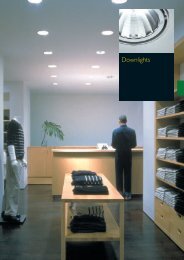
L939E939_SRC.QXD 11-03-2004 08:06 Pagina 12.1<br />
<strong>General</strong><br />
<strong>information</strong>,<br />
<strong>optic</strong> <strong>specifications</strong>,<br />
<strong>index</strong>
L940D941_SRC.QXD 11-03-2004 08:10 Pagina 12.2<br />
Guidelines for easy selection – Explanation of type numbers<br />
To help you specify we have developed two product categories:<br />
Luminaire programmes and Modular programmes.<br />
Each category has its own specifying and ordering procedures:<br />
Luminaire programmes<br />
A ‘Luminaire specification’<br />
table is a simple product listing.<br />
Each product is listed alongside<br />
its standard features such as the<br />
number of lamps, lamp colour<br />
<strong>optic</strong> type, etc. Please order<br />
these through your normal<br />
Philips Lighting supplier.<br />
Modular programmes<br />
Modular programmes describe<br />
product ranges that offer a wide<br />
choice of features and optional<br />
extras – you choose the<br />
combination.The ‘Luminaire<br />
specification’ tables (see example<br />
below) show what is possible.<br />
Simply choose one item from<br />
each column to form the full<br />
type number.<br />
Luminaire specification (standard combinations)<br />
600<br />
600 D/I<br />
no<br />
840<br />
827<br />
Preferred selection<br />
12.2 GENERAL INFORMATION, OPTIC SPECIFICATIONS, INDEX<br />
Optional features<br />
If you want to include some<br />
non-standard features, such as<br />
3 hour emergency light, or<br />
Luxsense lighting control, Philips<br />
will incorporate these at the<br />
factory for you, effectively<br />
producing a tailor-made<br />
luminaire as a standard product.<br />
The table ‘Optional choices’ (see<br />
example below) shows what is<br />
possible.<br />
Preferred selection<br />
The most popular versions of<br />
each product range are listed<br />
under the ‘Preferred selection’<br />
table (see example below).<br />
The page opposite shows some<br />
example definitions of typical<br />
terms used in the selection<br />
tables.<br />
Product ID Optics Weight<br />
Light Output<br />
European Order<br />
(kg)<br />
Ratio (LOR)<br />
Code (EOC)<br />
TCS600 1XTL5-28W/830 HFP D C7 FL C7 3.2 0.85 05303500<br />
TCS600 1XTL5-49W/830 HFP D C7 FL C7 4.0 0.85 43101700<br />
TCS600 2XTL5-28W/830 HFP D C7 FL C7 4.4 0.83 05308000<br />
TCS600 2XTL5-35W/830 HFP D C7 C7 5.5 0.82 05911200<br />
TCS600 2XTL5-35W/830 HFP D C7 FL C7 5.5 0.82 05314100<br />
TCS600 1XTL5-28W/830 HFP D D7 FL D7 3.2 0.85 05304200<br />
TCS600 1XTL5-35W/830 HFP D D7 FL D7 4.0 0.85 05282300<br />
TCS600 1XTL5-49W/830 HFP D D7 FL D7 4.0 0.82 43100000<br />
TCS600 2XTL5-28W/830 HFP D D7 FL D7 4.4 0.82 05283000
L940D941_SRC.QXD 11-03-2004 08:10 Pagina 12.3<br />
The method used for<br />
type numbers is explained in the<br />
following.This explanation<br />
covers the major part of the<br />
type numbers.<br />
1st letter<br />
Lamp category<br />
Indicates the lamp type or<br />
non-luminaire product types<br />
B Luminaires for LEDs<br />
C Combinations of lamps<br />
F Compact fluorescent<br />
G Attachments (<strong>optic</strong>al)<br />
H Gas discharge luminaires<br />
K Special lamps (e.g. QL lamps)<br />
L Low voltage (halogen)<br />
M Compact discharge<br />
P Projection lamps<br />
Q Mains voltage incandescent<br />
(incl. halogen)<br />
R Power tracks<br />
(incl. accessories)<br />
T Linear fluorescent luminaires<br />
V Terminations for fibre <strong>optic</strong>s<br />
Z Accessories<br />
2nd letter<br />
Mounting position<br />
Indicates the mounting or<br />
version<br />
B Recessed<br />
C Surface<br />
D Desktop<br />
F Floor<br />
G Special<br />
K Electrical components<br />
M Electrical unit (batten)<br />
P Suspended/pendant<br />
R Power track mounted<br />
T Trunking<br />
WWall<br />
Z Multi-use/functional accessory<br />
3rd letter<br />
Design/application<br />
Indicates the type of usage<br />
G Decorative<br />
H Special<br />
K High and low bay<br />
L Components<br />
N Air-handling<br />
S Stand-alone<br />
V Fibre <strong>optic</strong>s<br />
WWaterproof<br />
X Systems/structures<br />
Z Increased safety<br />
TCS 600<br />
The next three digits in the designation<br />
indicate the family of luminaires.<br />
For the precise choice of<br />
luminaire for a particular lighting<br />
assignment it is advisable to<br />
contact a representative of<br />
Philips Lighting.<br />
1xTL5-28W/840 HFP M-DGN<br />
Family name<br />
Key-words Lamp (example): Description<br />
1xTL5-28W/840 1 x TL5 fluorescent lamp 28 Watt lampcolour 840<br />
2xTL-D36W 2 x TL-D fluorescent lamp 36 Watt<br />
1xA60-MAX100W 1 x incandescent lamp with conventional pear shape<br />
E27 lampsocket for maximum 100 Watt<br />
1xHAL-PR50W-GU5.3 1 x halogen dichroic reflector lamp 50 Watt 12 volts<br />
with lampbase GU5.3<br />
1xHAL-C50W/12V-GY6.35-SI 1 x halogen capsule lamp 50 Watt 12 volts in silver<br />
with lampbase GY6.35<br />
1xSDW-T50W 1 x White SON lamp (SDW-T) 50 Watt<br />
1xCDM-T70W 1 x MASTER Colour lamp T-version (CDM-T) 70 Watt<br />
1xCDM-TD100W 1 x MASTER Colour lamp TD-version (CDM-TD)<br />
100 Watt<br />
1xPL-S/2P9W 1 x compact fluorescent PL-S lamp / 2pins / 9 Watt<br />
2xPL-C/4P18W/830 2 x compact fluorescent PL-C lamp / 4 pins / 18 Watt<br />
lampcolour 830<br />
Key-words Gear (example): Description<br />
HFB basic version of HF electronic gear for fluorescent<br />
lamps<br />
HFP performer version of HF electronic gear for<br />
fluorescent lamps<br />
HFR regulated version of HF electronic gear for<br />
fluorescent lamps<br />
HFD regulated DALI addressable version of HF electronic<br />
gear for fluorescent lamps<br />
EI electronic included<br />
IC electromagnetic gear, parallel compensated<br />
Key-words Optics* (example): Description<br />
C7 OLC high gloss <strong>optic</strong> with 3D lamellae<br />
D7 OLC semi high gloss <strong>optic</strong> with 3D lamellae<br />
M6 OLC matt aluminium <strong>optic</strong> with 3D lamellae<br />
M2 matt aluminium <strong>optic</strong> with flat profiled cross lamellae<br />
M-DGN matt aluminium <strong>optic</strong> with greenish cross lamellae<br />
OD prismatic/opal cover<br />
*For <strong>optic</strong> description see page 12.20-12.24.<br />
GENERAL INFORMATION, OPTIC SPECIFICATIONS, INDEX 12.3
L942D943_SRC.QXD 11-03-2004 08:14 Pagina 12.4<br />
Information – Specification data luminaires<br />
Safety and protection of luminaires<br />
Approvals and standards<br />
Luminaires sold in the market are expected to comply with the<br />
appropriate safety rules as laid down in the European standard EN<br />
60598 prepared by the CEN/CENELEC (the European Committee<br />
for Electrotechnical Standardisation).<br />
AEE<br />
MARKA DE CONFORMIDAD A NORMAS UNE<br />
12.4 GENERAL INFORMATION, OPTIC SPECIFICATIONS, INDEX<br />
As European norms are taken over in the national norms and<br />
published as such, all electrical equipment available in Europe should<br />
comply with these norms.The European testing institutes<br />
introduced the ENEC logo in January 1993.<br />
All luminaires supplied by Philips Lighting comply with the most<br />
recent European directives as indicated by the ENEC and CE marking<br />
on the product and packaging.<br />
01<br />
AENOR - Spain<br />
IMQ - Italy<br />
03<br />
05<br />
KEMA -<br />
The Netherlands<br />
SEE -<br />
Luxemburg<br />
07<br />
ELOT - Greece<br />
ÖVE - Austria<br />
SEV -<br />
Switserland<br />
DEMKO -<br />
Danmark<br />
NEMKO -<br />
Norway<br />
EZU -<br />
Czeck Republic<br />
CEBEC -<br />
Belgium<br />
02<br />
04<br />
IPQ - Portugal<br />
06<br />
NSAI - Ireland<br />
UTE - France<br />
08<br />
VDE - Germany<br />
BSI -<br />
United Kingdom<br />
SEMKO -<br />
Sweden<br />
FIMKO -<br />
Finland<br />
MEEi - Hungary<br />
SIQ -<br />
Slovenia
L942D943_SRC.QXD 11-03-2004 08:14 Pagina 12.5<br />
Electrical supply<br />
An important step to harmonise the European market is the definition<br />
of a uniform electrical voltage. From 2003 onwards the voltage<br />
is 230 V/400 V with a tolerance of 10%.<br />
Philips Lighting indoor luminaires are designed for the future and will<br />
operate well on the supply of today and tomorrow.An example is<br />
electronic ballasts designed for a rated mains voltage of 220-240 V,<br />
with tolerance for safety of +/- 10% and tolerances for performance<br />
of –8% and +6% covering the full range between 202 V and 254 V.<br />
Ambient temperature<br />
Philips indoor luminaires are designed to meet the (environmental)<br />
conditions under which they are most likely to be used.<br />
The maximum ambient temperature Ta under which a luminaire can<br />
be safely applied, is indicated on the label on the products; if no<br />
indication is given the product is meant for a maximum ambient<br />
temperature of 25°C.The ambient temperature always refers to the<br />
typical use of the luminaire: indoors or outdoors.The majority of<br />
luminaires developed for office, shop and general indoor applications<br />
show no T a , thus meaning 25°C. Luminaires designed for industrial<br />
high-bay applications are designed for ambient temperatures as high<br />
as 40 to 45°C.The use of luminaires above their specified maximum<br />
ambient temperature may reduce safety margins and will in any case<br />
lead to a reduction of the lifetime of the various components;<br />
especially electronic equipment (ballasts and controls) is sensitive to<br />
overheating and lifetime will be reduced.Although using luminaires at<br />
(extremely) low temperatures does not normally affect safety, the<br />
operating (especially starting) of the lamp may be influenced.<br />
Fluorescent lamps should not be used below –5°C to –10°C,<br />
whereas high-intensity discharge lamps function well below –20°C.<br />
Upon request special solutions are often possible for higher or lower<br />
ambient temperatures.<br />
Electrical safety (classes)<br />
Electrical equipment is classified according to protection against<br />
electrical shock. In normal operation as well as during service and<br />
maintenance, luminaires should be protected against electrical shock.<br />
The safety of a luminaire depends on electrical, mechanical and<br />
thermal aspects; both under normal and fault conditions.<br />
The electrical safety classification drawn up by the IEC embraces<br />
four luminaire classes: Class 0, I, II and III. Class 0 luminaires are not<br />
available from Philips Lighting. Class III is only applicable to Safety<br />
Extra-Low Voltage luminaires (SELV).The table gives a brief<br />
description of each electrical safety class.The official definitions are<br />
too long to be reproduced in full here, but can be summarised as<br />
printed below. If a proper earth connection is available, Class I<br />
luminaires are applied. However, when no earth connection, or only a<br />
poor-quality earth connection is available, or where eddy currents<br />
are present, Class II luminaires shall be applied. Class II waterprotected<br />
luminaires are applied in (semi-)outdoor locations. Local<br />
electricity boards can provide the appropriate advice.<br />
Class I - symbol<br />
Luminaires in this class, besides being electrically insulated, are also<br />
provided with an earthing point (labelled) connecting all those<br />
exposed metal parts that could conceivably become live in the<br />
presence of a fault condition.<br />
Where the luminaire is provided with a flexible power lead, this must<br />
include an earth wire.Where this is not the case, the degree of<br />
electrical protection afforded by the luminaire is the same as that<br />
afforded by Class 0.<br />
Where a connection block is employed instead of a power lead, the<br />
metal housing must be connected to the earth terminal on the block.<br />
The provision made for earthing the luminaire must in all other<br />
respects satisfy the requirements laid down for Class I.<br />
Class II - symbol<br />
Class II luminaires are so designed and constructed that exposed<br />
metal parts cannot become live.This can be achieved by means of<br />
either reinforced or double insulation, there being no provision for<br />
protective earthing. In the case of a luminaire provided with an earth<br />
contact as an aid to lamp starting, but where this earth is not<br />
connected to exposed metal parts, the luminaire is nevertheless<br />
regarded as being of Class I.<br />
A luminaire having double or reinforced insulation and provided with<br />
an earth connection or earth contact must be regarded as a Class I<br />
luminaire.<br />
However, where the earth wire passes through the luminaire as part<br />
of the provisions for through-wiring the installation, and it is<br />
electrically insulated from the luminaire using Class II insulation, then<br />
the luminaire remains Class II.<br />
Class III - symbol<br />
The luminaires in this class are those in which protection against<br />
electric shock relies on supply at Safety Extra-Low Voltage (SELV),<br />
and in which voltages higher than those of SELV (50 V a.c. r.m.s.) are<br />
not generated. An a.c. operating voltage of 42 V maximum is common.<br />
A Class III luminaire should not be provided with a means for<br />
protective earthing.<br />
Protection against electrical shock<br />
Safety class Symbol Protection<br />
0<br />
Basic insulation only (not recommended)<br />
Basic insulation plus protective earth<br />
connector<br />
Double or reinforced insulation, no<br />
provision for protective earthing<br />
Supply of safety extra-low voltage<br />
GENERAL INFORMATION, OPTIC SPECIFICATIONS, INDEX 12.5
L944D945_SRC.QXD 11-03-2004 08:14 Pagina 12.6<br />
Information – Specification data luminaires<br />
Protection against ingress of solid bodies, dust and<br />
moisture<br />
The Ingress Protection system (IP) EN 60529, 1991 defines various<br />
degrees of protection against the ingress of foreign bodies, dust and<br />
moisture.The term ‘foreign bodies’ includes things like fingers and<br />
tools coming into contact with the electrical live parts of the<br />
luminaire.<br />
Both safety aspects (contact with live parts) and harmful effects on<br />
the function of the luminaire are defined.The exact testing method<br />
for each IP classification is described in EN 60529.<br />
Note that the conditions during testing might differ from the specific<br />
conditions in an application.<br />
The designation to indicate the degree of protection consists of the<br />
characteristic letters IP followed by 2 digits indicating conformity<br />
with the conditions stated in the two tables.All Philips Lighting<br />
luminaires fulfil the minimum classification: IP 20 (protected against<br />
finger contact with live parts), however a selection of luminaires,<br />
especially those for industrial applications, meet a higher IP<br />
classification.<br />
It is important to realise that the specification and safety of<br />
luminaires are only secured if the necessary maintenance according<br />
to the instructions of the manufacturer is carried out in time.<br />
Luminaires are not available in all possible combinations of ingress<br />
and moisture protection.The most common applications of the IP<br />
classifications for luminaires are:<br />
IP 20<br />
Luminaires which can be applied indoors only if no specific pollution<br />
rates are expected. Offices, dry, heated industrial halls, shops,<br />
shopping malls and theatres are typical application segments.<br />
IP 21/22<br />
Luminaires which can be applied in unheated (industrial) halls and<br />
under canopies as the luminaires are drip-and condensation-waterprotected.<br />
IP 23<br />
Luminaires which can be applied in unheated industrial halls or<br />
outdoors.<br />
IP 43/44<br />
Luminaires and bollards for outdoor street lighting and street<br />
lanterns. Bollards mounted at a low height are protected against<br />
small solid objects and against rain and splash.<br />
A common combination within an industrial high-bay luminaire or<br />
street lantern is IP 43 for the electrical part of the luminaire, to<br />
secure safety, and IP 54/65, for the <strong>optic</strong>al part of the Iuminaire, to<br />
prevent pollution of reflector and lamp.<br />
IP 50<br />
Luminaires which are applied in dusty environments, to prevent rapid<br />
pollution of the luminaire.<br />
The exterior of IP 50 luminaires can be cleaned easily. In the food<br />
industry, closed luminaires are specified to prevent glass particles<br />
from accidentally broken lamps entering the production area and<br />
contaminating the products under preparation.<br />
Although ingress protection is specified to protect the luminaire<br />
function, it also means that particles cannot leave the luminaire<br />
housing, thereby meeting the specification of the food industry.<br />
12.6 GENERAL INFORMATION, OPTIC SPECIFICATIONS, INDEX<br />
In the ‘wet’ food industry, luminaires meeting the IP 50 classification<br />
shall not be applied.<br />
IP 54<br />
The traditional water-protected classification. Luminaires can be<br />
cleaned with water without any harmful effect.This classification is<br />
often specified in the food processing industry, for industries where<br />
dust and moisture are generated in the hall, and for use under<br />
canopies.<br />
IP 60<br />
Luminaires which are completely sealed against dust accumulation,<br />
and are used in very dusty environments (wood and textile industry,<br />
stone carving) and in the food industry as explained above. IP 60<br />
luminaires are rarely applied; IP 65/IP 66 is usually applied instead.<br />
IP 65/66<br />
Jet-proof Iuminaires which are applicable where the surroundings are<br />
hosed down frequently by water jets, or where luminaires are<br />
applied in a dusty environment.Although the luminaires are not fully<br />
watertight, the potential ingress of moisture will not have any<br />
harmful effect on the luminaire function. IP 65/66 luminaires are<br />
often available in impact-protected versions.<br />
IP 67/68<br />
Luminaires complying with this classification are suitable for<br />
immersion in water.<br />
Typical application areas are underwater lighting of swimming pools<br />
and fountain Iighting.<br />
Deck lighting on ships should also meet this classification.<br />
The test method does not imply that IP 67/68 Iuminaires meet the<br />
IP 65/66 classifications as well.<br />
High-bay luminaires illuminate an IP 20 classified area.
L944D945_SRC.QXD 11-03-2004 08:14 Pagina 12.7<br />
Protection against ingress of dust, solid objects and moisture<br />
First number: Second number:<br />
Degree of protection against accidential contact/ Degree of protection against ingress of moisture<br />
contact with external elements<br />
First Second<br />
number Description Explanation number Description Explanation<br />
0<br />
1<br />
2<br />
3<br />
4<br />
5<br />
6<br />
Non-protected Not protected<br />
Hand-protected<br />
Fingerprotected<br />
Tool-protected<br />
Wire-protected<br />
Dustaccumulationprotected<br />
Dustpenetrationprotected<br />
Protected against solid objects<br />
exceeding 50 mm in diameter<br />
Protected against finger contact<br />
with live parts; and against solid<br />
objects exceeding 12 mm in<br />
diameter<br />
Protected against contact with live<br />
parts by tools, wire or similar<br />
objects over 2.5 mm thick; and<br />
protection against penetration of<br />
solid objects exceeding 2.5 mm in<br />
diameter<br />
Protected against contact with live<br />
parts by tools, wire or similar objects<br />
over 1 mm thick; protection<br />
against penetration of solid objects<br />
exceeding 1 mm in diameter<br />
Complete protection against<br />
contact with live parts and against<br />
harmful accumulation of dust;<br />
some dust may penetrate but not<br />
to the extent that operation is<br />
impaired<br />
Complete protection against<br />
contact with live parts and against<br />
penetration of dust<br />
0<br />
1<br />
2<br />
3<br />
4<br />
5<br />
6<br />
7<br />
8<br />
Non-protected<br />
Drip-proof<br />
against vertical<br />
water drops<br />
Drip-proof<br />
when tilted at<br />
angles up to<br />
15°<br />
Rain-/sprayproof<br />
Splash-proof<br />
Not protected against moisture<br />
Water drips falling vertically shall<br />
have no harmful effect<br />
Water drips shall have no harmful<br />
effect<br />
Water falling at an angle of up to<br />
60° shall have no harmful effect<br />
Splashing water from any direction<br />
shall have no harmful effect<br />
Jet-proof Water projected by a nozzle from<br />
any direction shall have no harmful<br />
effect. (Nozzle diameter 6.3 mm,<br />
pressure 30 kPa)<br />
Jet-proof<br />
Water projected by a nozzle from<br />
any direction shall have no harmful<br />
effect. (Nozzle diameter 12.5 mm,<br />
pressure 100 kPa)<br />
Watertight Watertight; temporary immersion<br />
in water under specified<br />
conditions of pressure and time<br />
possible without ingress of water<br />
in harmful quantities<br />
Pressure<br />
watertight<br />
Pressure watertight; continuous<br />
submersion in water under<br />
specified conditions of pressure<br />
and time without ingress of water<br />
in harmful quantities<br />
GENERAL INFORMATION, OPTIC SPECIFICATIONS, INDEX 12.7
L946D947_SRC.QXD 11-03-2004 08:15 Pagina 12.8<br />
Information – Specification data luminaires<br />
Protection against mechanical shock<br />
The impact resistance of a luminaire defines the protection of the<br />
luminaire against mechanical shock.The European norm EN 50102<br />
defines the degrees of protection against external mechanical impact<br />
(IK code) and the method of testing.The luminaire housing should<br />
withstand the defined energy of the mechanical shock without losing<br />
its electrical and mechanical safety, or the basic luminaire function.<br />
Translated into a more practical implementation, this means that<br />
after withstanding the shock, deformation of the mirror and housing<br />
is allowed, although broken lamps, an unsafe electrical situation and<br />
failure to meet the specified IP classifications are not permitted.<br />
The impact resistance is expressed as a group numeral, for instance<br />
IK06, which is related to the impact energy in joule.<br />
Ball impact resistance<br />
Especially for indoor sports halls, ball-impact-resistant luminaires are<br />
essential.As no European norms have been developed, Philips<br />
Lighting has classified the relevant luminaires according to the<br />
German DIN 18032.According to this norm, luminaires should be<br />
tested with a ball shooting machine: the luminaire should be targeted<br />
by 36 handballs with a speed of 60 km/h.<br />
After the test, no essential damage to the luminaire should have<br />
occured.<br />
No loose particles should drop down from the luminaire.<br />
The symbol for a ball-impact-resistant luminaire is a football.<br />
Luminaires with a grid width exceeding 60 mm are not to<br />
be used in tennis sports halls.<br />
Flammability<br />
From the point of view of flammability, luminaires can always be<br />
mounted on non-flammable building materials like concrete and<br />
stone. However, when mounting luminaires on flammable materials<br />
special measures should be taken. Luminaires for discharge lamps<br />
with an F-sign are suitable to be mounted on building surfaces which<br />
do not ignite below 200°C.<br />
Luminaires for discharge lamps with an FF-sign have a limited surface<br />
temperature, and are suitable to be mounted on easily flammable<br />
surfaces.<br />
All types of luminaires of Philips Lighting have a minimum impact<br />
resistance of 0.2 J.The table shows the ten IK classifications and the<br />
defined shock energy in joule.<br />
For example: an IK07 classified luminaire can withstand a mechanical<br />
shock of a pendulum hammer, a spring hammer or a free-falling<br />
hammer of 2 joule (e.g. a hammer of 0.5 kg falling 0.40 m).<br />
Note that vandal-proof Iuminaires are not available: vandal-protected<br />
and vandal-resistant are the best achievable classifications.<br />
Protection against mechanical shock<br />
IK code Shock energy (Joule) Description Example<br />
IK00 -<br />
IK01 0.15<br />
IK02 0.2 Standard Standard open luminaire, closed luminaire with acrylic cover<br />
IK03 0.3<br />
IK04 0.5 Standard plus Open luminaire with reinforced <strong>optic</strong>al system<br />
IK05 0.7<br />
IK06 1<br />
IK07 2 Reinforced<br />
IK08 5 Vandal-protected Closed luminaire with polycarbonate or hardened glass cover<br />
IK09 10<br />
IK10 20 Vandal-resistant Closed<br />
12.8 GENERAL INFORMATION, OPTIC SPECIFICATIONS, INDEX<br />
Luminaire marking for flammability:<br />
Symbol Application Characteristics of<br />
ceiling material<br />
None Suitable for mounting on Stone, concrete<br />
non-flammable surfaces<br />
Suitable for mounting on Ignition temperature<br />
F<br />
normally flammable materials<br />
surfaces > 200°C; some combustion<br />
time lag.<br />
F F<br />
Suitable for mounting on Ignition temperature<br />
easily flammable surfaces materials<br />
< 200°C; no combustion<br />
time lag<br />
… m<br />
Safety distance<br />
Especially in the application of reflector lamps and luminaires with<br />
narrow beam distributions, a minimum distance between light source<br />
and illuminated surface has to be ensured.This is to prevent too high<br />
temperatures.Values for safety distances are specified on the<br />
luminaire's packing.The specified values must be considered as the<br />
shortest distances permitted between the light source and the<br />
illuminated surface or object.
L946D947_SRC.QXD 11-03-2004 08:15 Pagina 12.9<br />
Gear types<br />
Fluorescent lamps and high-intensity discharge lamps require a device<br />
to limit the current due to the negative current-voltage<br />
characteristics.Traditionally this is realised with electromagnetic<br />
control gear in combination with either a glow-switch or electronic<br />
starter.Almost the complete range of fluorescent and high-intensity<br />
discharge luminaires of Philips Lighting are available with the<br />
electromagnetic ballast system. From the point of view of energy<br />
consumption, the electromagnetic control gear system is not<br />
efficient: the losses in the ballast system are relatively high, and<br />
significant improvements are possible by applying electronic control<br />
gear instead.<br />
Electronic control gear offers a number of advantages in comparison<br />
with traditional electromagnetic ballasts:<br />
- The electronic ballast offers interesting cost savings, such as a<br />
reduction in energy consumption of about 25%, a substantial<br />
extension of the lamp life up to 50% and thus a lowering of<br />
maintenance costs.<br />
- Application of electronic ballasts adds to the comfort in numerous<br />
ways: no cathode flicker occurs; at the end of lamp life the lamp is<br />
automatically switched off; smooth and rapid starting is ensured<br />
without flickering; and no stroboscopic effects can arise due to the<br />
high frequency at which the lamps are operated.<br />
- Extra safety is assured through over-voltage detection, protected<br />
control of the mains voltage input and a noticeably lower operating<br />
temperature.<br />
- Flexibility is enhanced: installations with fluorescent lamps, for<br />
instance, are dimmable if a regulating ballast is selected, allowing for<br />
adjustment of lighting levels to personal preference and the<br />
opportunity for additional savings on energy, e.g. by daylight-linked<br />
lighting control.<br />
Following the trend towards greater efficiency and comfort, some<br />
of the newer fluorescent lamps like all TL5 and high-wattage<br />
PL-L types will operate only on electronic control gear.<br />
Philips offers four options when selecting high-frequency ballasts<br />
for fluorescent lamps: HF-BASIC for situations with infrequent onand-off<br />
switching; HF-PERFORMER where the demands are<br />
greater; HF-REGULATOR for areas where there is frequent<br />
dimming; and HF-DALI ballast working in accordensie with the<br />
DALI Protocol.<br />
- HF-DALI (HFD):<br />
Electronic regulating ballast for TL5, PL-L and TL-D lamps.<br />
The high-frequency regulating ballasts permit light output<br />
regulation down to 3% of the DALI control input.<br />
- HF-REGULATOR (HFR):<br />
Electronic regulating ballast for TL5, PL-L and TL-D lamps.<br />
These high-frequency regulating ballasts permit light output<br />
regulation down to 3% of the maximum light output by the 1-10 V<br />
control input. Up to 60% reduction in energy consumption can be<br />
achieved by using automatic lighting control systems like Luxsense<br />
or Multisense.All Philips HF-Regulator electronic ballasts are fitted<br />
with alpha-control.This dedicated integrated circuit ensures that<br />
lamp life is unaffected by the dimming position; that lamp burning is<br />
stable in every dimming position; and that energy savings are<br />
maximised when dimming.<br />
- HF-PERFORMER (HFP):<br />
Electronic ballast for TL5, PL-L and TL-D lamps.<br />
These high-frequency ballasts offer low energy consumption.<br />
A warm-start circuit preheating the lamp electrodes enables the<br />
lamp to be switched on and off without reducing useful life.<br />
- HF-BASIC (HFB):<br />
Electronic ballast for TL-D lamps (only for 36 W and 58 W lamps)<br />
These high-frequency ballasts offer low energy consumption.<br />
Luminaires with these ballasts are only to be applied in situations<br />
where switching is infrequent as the lamp electrodes are not preheated<br />
(‘cold start’) before ignition.<br />
Efficacy of fluorescent lamp systems – typical examples<br />
Lamp type Conventional Electronic gear<br />
gear HFR, HFP<br />
or HFB<br />
TL-D 18 W Lamp 4 x 18 W 4 x 16 W<br />
Ballast 14 W 10 W<br />
4-lamp Total 86 W 74 W<br />
system Lamp flux 4 x 1350 lumen 4 x 1400 lumen<br />
System efficacy 63 lumen/Watt 76 lumen/Watt<br />
Energy saving 16%<br />
potential<br />
TL-D 36 W Lamp 36 W 32 W<br />
Ballast 8 W 4 W<br />
1-lamp Total 44 W 36 W<br />
system Lamp flux 3350 lumen 3200 lumen<br />
System efficacy 76 lumen/Watt 89 lumen/Watt<br />
Energy saving 22%<br />
potential<br />
TL-D 58 W Lamp 58 W 50 W<br />
Ballast 11 W 5 W<br />
1-lamp Total 69 W 55 W<br />
system Lamp flux 5200 lumen 5000 lumen<br />
System efficacy 75 lumen/Watt 89 lumen/Watt<br />
Energy saving 26%<br />
potential<br />
TL5 HE 14 W Lamp 4 x 14 W<br />
Ballast Not available 6 W<br />
4-lamp Total 62W<br />
system Lamp flux 4 x 1350 lumen<br />
System efficacy 87 lumen/Watt<br />
TL5 HE 28 W Lamp 28 W<br />
Ballast Not available 4 W<br />
1-lamp Total 32 W<br />
system Lamp flux 2900 lumen<br />
System efficacy 91 lumen/Watt<br />
TL5 HO 49 W Lamp 49 W<br />
Ballast Not available 5 W<br />
1-lamp Total 54 W<br />
system Lamp flux 4900 lumen<br />
System efficacy 91 lumen/Watt<br />
,GENERAL INFORMATION, OPTIC SPECIFICATIONS, INDEX 12.9
L948D949_SRC.QXD 11-03-2004 08:16 Pagina 12.10<br />
Information – Specification data luminaires<br />
False ceilings<br />
Ceiling types – introduction<br />
Today, architects and building contractors can choose from an<br />
enormous variety of ceiling systems, especially ones designed for<br />
offices and other general applications. Use of climate ceilings<br />
(cooled) is growing.<br />
The four main standard ceiling types are:<br />
1.Visible profile ceilings<br />
2. Concealed profile ceilings<br />
3. Strip ceilings<br />
4. Panel ceilings<br />
Obviously, there are small differences between ceiling types, but the<br />
application of luminaires and the accessories you will need for<br />
mounting them are the same for all the systems.<br />
The four standard system types discussed here represent the vast<br />
majority of ceiling systems currently available.Also real “projectmade”<br />
plaster ceilings are used more and more and seen as<br />
aesthetical pleasing solutions. If you decide to use another type of<br />
system, contact your Philips organisation and they will inform you<br />
about the options in your specific situation. If no standard solution is<br />
available, a special solution in the luminaire concept can be discussed.<br />
1. Visible profile ceilings<br />
In this very common system, profiles are<br />
always visible. Ceiling tiles rest on the<br />
profiles and are in most cases made from<br />
a mineral material.<br />
The two standard module sizes are<br />
300 mm and 312,5 mm.<br />
The most popular tiles in this type of<br />
ceiling are for ceiling grids of 600x600 mm<br />
and 600x1200 mm, or 625x625 mm and<br />
625x1250 mm. In this type of ceiling,<br />
luminaires will be mounted as an inlay.<br />
Applications<br />
These ceiling types are usually used when<br />
electrical wiring, LANs and other technical<br />
installations are hidden behind the ceiling.<br />
Also in this application the ceiling should<br />
contribute to the acoustic environment.<br />
All Philips recessed luminaires are suitable<br />
for this kind of ceiling.<br />
12.10 GENERAL INFORMATION, OPTIC SPECIFICATIONS, INDEX<br />
Ceiling tile materials<br />
Different ceiling types use panels or tiles of different materials.<br />
The most popular materials are:<br />
Mineral (hard and soft)<br />
These are produced in thicknesses between 14 and 20 mm.<br />
Mineral tiles are usually painted and always mechanically vulnerable.<br />
Acoustic qualities of these types of ceilings are reasonable.<br />
Plaster<br />
Plaster ceilings are usually 10-15 mm thick and are non-removable<br />
ceilings. If recessed luminaires are to be used in this kind of ceiling<br />
an opening has to be cut out before mounting the luminaire.<br />
Metal<br />
Metal is used in tiles, strips and/or panels. In some cases they are<br />
perforated and have a sound-insulating layer on top.This layer helps<br />
to create good acoustic quality. Recessed luminaires are usually<br />
designed so that they can replace a complete ceiling tile.
L948D949_SRC.QXD 11-03-2004 08:16 Pagina 12.11<br />
2. Concealed profile ceilings<br />
In this type of ceiling, the profiles are<br />
covered by the tile and are not visible.<br />
Tiles are made from a mineral type of<br />
material or metal. In these types of<br />
systems, suspension brackets are always<br />
needed.<br />
3. Strip ceilings<br />
This ceiling system consists of main<br />
carriers on which metal strips are clicked.<br />
They have various widths. Luminaires are<br />
usually mounted in line with the strips and<br />
perpendicular to the main carriers. In that<br />
case, a length profile mounted to the side<br />
of the luminaire is required, or suspension<br />
brackets at the head of the luminaire when<br />
the luminaire fits in exactly between two<br />
main carriers. (See figures)<br />
4. Panel ceiling systems<br />
The main carriers of these systems are<br />
usually placed at the main building modules.<br />
These are often 1200 or 1800 mm. Ceiling<br />
panels are mounted between the main<br />
carriers. In this type of ceiling, metal and<br />
mineral panels are used.<br />
If the distance between the main carriers<br />
does not fit with the luminaire length<br />
these luminaires can be lengthened so that<br />
they can be mounted between the main<br />
carriers. For profile A, the luminaire can<br />
be mounted as an inlay. Safety brackets<br />
can be delivered on request with the<br />
luminaire.<br />
When profile B is used, brackets are<br />
required and must be ordered separately.<br />
Also a 100% copy of the ceiling tile can be<br />
used with integrated luminaires.<br />
Applications<br />
Areas like corridors, airports, etc.<br />
Applications<br />
Areas where removable partition walls are<br />
used and acoustic performance of<br />
highquality is required. In corridors each<br />
panel can span the total width (e.g. 1.8 m).<br />
Fixation with ZBS300 CB Fixation with ZBS300 LP<br />
A<br />
GENERAL INFORMATION, OPTIC SPECIFICATIONS, INDEX 12.11<br />
B
L952D953_SRC.QXD 11-03-2004 08:19 Pagina 12.14<br />
Information – Lighting technique<br />
However, the luminous intensity graph in the cartesian intensity<br />
diagram gives a much better indication of the beam shape.The<br />
luminous intensity in the cartesian diagram is given in absolute candela<br />
values.Along the horizontal axis the -values of the C-plane are given,<br />
while the vertical axis shows the absolute intensity values in candela.<br />
Utilisation factor table<br />
Room<br />
Index<br />
k<br />
0.60<br />
0.80<br />
1.00<br />
1.25<br />
1.50<br />
2.00<br />
2.50<br />
3.00<br />
4.00<br />
5.00<br />
0.80<br />
0.50<br />
0.30<br />
0.43<br />
0.51<br />
0.57<br />
0.63<br />
0.67<br />
0.73<br />
0.77<br />
0.79<br />
0.82<br />
0.84<br />
0.80<br />
0.50<br />
0.10<br />
0.41<br />
0.48<br />
0.53<br />
0.58<br />
0.61<br />
0.65<br />
0.68<br />
0.69<br />
0.71<br />
0.72<br />
0.70<br />
0.50<br />
0.30<br />
0.42<br />
0.50<br />
0.56<br />
0.62<br />
0.66<br />
0.71<br />
0.75<br />
0.77<br />
0.79<br />
0.81<br />
0.70<br />
0.50<br />
0.20<br />
0.41<br />
0.49<br />
0.54<br />
0.59<br />
0.63<br />
0.68<br />
0.71<br />
0.72<br />
0.75<br />
0.76<br />
0.70<br />
0.50<br />
0.10<br />
0.40<br />
0.47<br />
0.53<br />
0.57<br />
0.60<br />
0.65<br />
0.67<br />
0.69<br />
0.70<br />
0.71<br />
0.70<br />
0.30<br />
0.10<br />
0.36<br />
0.43<br />
0.49<br />
0.54<br />
0.57<br />
0.62<br />
0.65<br />
0.67<br />
0.69<br />
0.70<br />
0.50<br />
0.30<br />
0.10<br />
0.36<br />
0.43<br />
0.48<br />
0.53<br />
0.56<br />
0.61<br />
0.64<br />
0.66<br />
0.68<br />
0.69<br />
0.50<br />
0.10<br />
0.10<br />
0.33<br />
0.40<br />
0.46<br />
0.51<br />
0.54<br />
0.60<br />
0.63<br />
0.65<br />
0.67<br />
0.68<br />
The Utilisation Factor table enables the lighting designer to<br />
determine the number of luminaires required, or to calculate the<br />
illuminance realised with a certain lighting installation.Although a lot<br />
of calculation work has been taken over by computer, the Utilisation<br />
Factor table is still a handy tool for lighting designers.The Utilisation<br />
Factor (UF) of a lighting installation represents the percentage of the<br />
luminous flux of the lamp(s) that reaches the defined working plane<br />
in the room, which has to be seen as the efficiency of the lighting<br />
installation.The Utilisation Factor depends on:<br />
- light distribution of the luminaire<br />
- luminaire efficiency<br />
- reflection of ceiling, walls and floor/working plane of the room<br />
- room <strong>index</strong> k<br />
The room <strong>index</strong> k represents the geometrical ratio of the room, and<br />
can be expressed as:<br />
0.30<br />
0.30<br />
0.10<br />
0.35<br />
0.42<br />
0.48<br />
0.53<br />
0.56<br />
0.60<br />
0.63<br />
0.65<br />
0.67<br />
0.67<br />
0.30<br />
0.10<br />
0.10<br />
0.33<br />
0.40<br />
0.45<br />
0.50<br />
0.54<br />
0.59<br />
0.62<br />
0.64<br />
0.66<br />
0.67<br />
0.00<br />
0.00<br />
0.00<br />
0.32<br />
0.39<br />
0.44<br />
0.49<br />
0.53<br />
0.58<br />
0.60<br />
0.62<br />
0.64<br />
0.65<br />
k =<br />
L x W<br />
Hwp ( L + W)<br />
Where:<br />
L = length of the room (m)<br />
W = width of the room (m)<br />
Hwp = height or vertical distance between the luminaires<br />
and the working plane<br />
Lumen method:<br />
The UF can be looked up in the table for a range of values of the<br />
room <strong>index</strong> k and a number of reflection value combinations.After<br />
determining the UF for the specific layout for a luminaire, the<br />
number of luminaires for a specific illumination level can be<br />
calculated with the formula:<br />
E x A<br />
N =<br />
x UF x MF<br />
Alternatively, knowing the number of luminaires, the resulting<br />
illuminance can be calculated with the formula:<br />
x N x UF x MF<br />
EAV =<br />
Reflectances (%) for ceilings, walls and working plane<br />
Recessed mounted<br />
A<br />
12.14 GENERAL INFORMATION, OPTIC SPECIFICATIONS, INDEX<br />
Where:<br />
N = required number of luminaires<br />
EAV = specified average illuminance in lux<br />
n = nominal lamp flux per luminaire (lumen)<br />
UF = utilisation factor<br />
MF = maintenance factor<br />
A = surface area of the room (m 2<br />
)<br />
Quantity estimation diagram<br />
Number of luminaires<br />
hroom: 2.8 m<br />
Reflectances: 0.70, 0.50, 0.20<br />
60 Maintenance factor: 1.0<br />
Recessed mounted<br />
45<br />
30<br />
15<br />
750 lx<br />
500 lx<br />
300 lx<br />
0<br />
20 60 100 140<br />
2<br />
180 (m )<br />
The quantity estimation diagram gives a quick insight into the number of<br />
luminaires that will be needed to reach the desired illuminance in a room.<br />
The diagram gives the number of luminaires of one type needed for<br />
different lighting levels, as a function of the area to be illuminated.Three<br />
different diagrams exist.They are based on three fixtures' mounting<br />
heights (2.8, 6 or 9 m, depending on the typical application,) and are made<br />
for fixed reflection factors, as indicated in the diagram.The quantity<br />
estimation diagram should only be used when the luminaires are placed<br />
in a regular pattern, in, on or suspended from the ceiling. For calculation<br />
purposes the space to be illuminated is considered to be rectangular.<br />
The example shows that if 750 lux is required in an area of 100 m 2<br />
,32<br />
luminaires have to be installed.The <strong>information</strong> from this diagram should<br />
be considered as a guideline. For exact figures, the lumen method or<br />
computer calculations are required.The maintenance factor used for this<br />
diagram is 1.0 but in practical situations a real maintenance factor has to<br />
be taken into consideration.<br />
Unified Glare Rating diagram (UGR)<br />
hroom: 2.8 m<br />
Reflectances: 0.70 0.500.20<br />
Ceiling mounted<br />
: viewed endwise<br />
: viewed crosswise<br />
: Parallel to viewing<br />
direction<br />
The Unified Glare Rating is an indication of the direct glare<br />
perceived in a certain space illuminated by artificial lighting.<br />
According to CEN (European Committee for Standardisation) the<br />
Unified Glare Rating (UGR) should be determined according to the<br />
CIE tabular method.
L952D953_SRC.QXD 11-03-2004 08:19 Pagina 12.15<br />
UGR is given in 5 classes (UGR= 16, 19, 22, 25 and 28; the lower<br />
the UGR, the less direct glare is perceived from the total of the<br />
luminaires in the installation).As the CIE tabular method does not<br />
give a quick insight into the UGR characteristics of a specific<br />
installation, Philips Lighting has developed the UGR diagram.<br />
For each installation with one type of luminaire, the UGR value to<br />
be expected in the application can be determined from this diagram.<br />
Note that the UGR values are given for two viewing directions to<br />
the luminaire, endwise and crosswise, and that the UGR might vary<br />
depending on the size of the space under consideration.The highest<br />
UGR value determines the quality of the installation. In the UGR<br />
diagram the UGR is represented for the specified height and<br />
reflection factors.<br />
Visual ambience diagram<br />
g<br />
h(m) 1<br />
2<br />
3<br />
4<br />
5<br />
800 400 200 100<br />
Eh<br />
(lx)<br />
1 2 3 4 5<br />
luminaire spacing (m)<br />
Downlights are often used for general lighting.Applying downlights,<br />
very attractive lighting with high contrast can be realised, but also<br />
diffuse uniform lighting.This very much depends on the light<br />
distribution of the specific downlight.<br />
The visual ambience diagram gives <strong>information</strong> on:<br />
- The spacing between the downlights required to obtain a certain<br />
average illuminance level at a specific mounting height.<br />
- The uniformity of the chosen lighting solution for different<br />
horizontal planes.<br />
Spacing:<br />
At the horizontal top axis, the average horizontal illuminance level is<br />
given (800, 400, 200, 100 and 50 lux). For each illuminance two<br />
curved lines are visible in the diagram:<br />
- the left curve is valid for a small room with 4 x 4 luminaires in a<br />
square arrangement.<br />
- the right curve is valid for a large room with 10 x 10 luminaires in<br />
a square arrangement.<br />
For narrow-beam luminaires the differences between the small-room<br />
luminaire arrangement and the large-room installation are minor,<br />
resulting in one curved line only.<br />
The distance between the luminaire and the reference plane, on<br />
which the average horizontal illuminance is calculated, is indicated on<br />
the left vertical axis.<br />
The luminaire spacing to obtain the selected horizontal illuminance<br />
at the specified distance from the ceiling can be found on the lower<br />
horizontal axis.<br />
Emin<br />
Emax<br />
0.1<br />
0.3<br />
0.6<br />
Uniformity:<br />
The resulting uniformity for the selected spacing can be read from<br />
the diagram for various horizontal planes.The uniformity is defined<br />
as Emin /Emax.Three straight sloping lines in the diagram indicate three<br />
uniformity values: 0.1, 0.3 and 0.6.The uniformity determines the<br />
lighting effect that will be obtained:<br />
-Emin /Emax > 0.6 (in the diagram below the 0.6 uniformity line).The<br />
arrangement of downlights creates diffused, uniform lighting, and so<br />
a ‘functional’ lighting ambience.<br />
- 0.1 < Emin /Emax < 0.6 (in the diagram in between the 0.6 and 0.1<br />
uniformity lines).The arrangement of downlights creates a lighting<br />
ambience that varies from lively to very contrasting.<br />
-Emin /Emax < 0.1 (in the diagram above the 0.1 uniformity line).<br />
The arrangement of downlights results in a non-uniform horizontal<br />
illuminance.The effect of the individual luminaires is clearly visible on<br />
the horizontal surface.<br />
In practice, it is important to check uniformity not only on the<br />
working plane, but also at different heights, for example at eye level. If<br />
the resulting uniformity is not in accordance with to the requirements<br />
of the application, another type of luminaire should be selected.<br />
Isolux diagram<br />
h(m)<br />
1<br />
/2E0<br />
o<br />
2 x 22<br />
Ehor<br />
(lx)<br />
1<br />
/ 2Imax<br />
o<br />
2 x 29 h<br />
(m)<br />
E0<br />
(lx)<br />
d(m)<br />
1 1<br />
/2E0 /2Imax<br />
1.0<br />
1.0 674 0.81 1.11<br />
500<br />
1.5 299 1.21 1.66<br />
2.0<br />
200<br />
2.0 168 1.62 2.22<br />
2.5 108 2.02 2.77<br />
3.0<br />
100<br />
3.0 75 2.42 3.33<br />
3.5 55 2.83 3.88<br />
4.0<br />
50<br />
4.0 42 3.23 4.43<br />
5.0<br />
4.5 33 3.64 4.99<br />
3.0 2.0 1.0 0.0 1.0 2.0 3.0 (m)<br />
The isolux diagram shows the illuminated area for rotationally<br />
symmetrical light distributions by means of isolux curves.<br />
The horizontal illuminance is indicated in relation to the distance<br />
(vertical and horizontal) to the luminaire.<br />
The shape of the isolux curves is dependent on the beam spread of<br />
the luminaire.<br />
1<br />
/ 2 E 0 and 1<br />
/ 2 Imax indicate this in the graph.Additionally, the connected<br />
table offers the user <strong>information</strong> on:<br />
- the resulting illuminance at the beam centre. (E 0)<br />
- the diameter of the area in which the illuminance is better or equal<br />
to 50% of the illuminance E 0.<br />
- the diameter of the area in which the luminous intensity is better<br />
or equal to 50% of Imax, the intensity in the beam centre.<br />
GENERAL INFORMATION, OPTIC SPECIFICATIONS, INDEX 12.15
L952D953_SRC.QXD 11-03-2004 08:21 Pagina 12.14<br />
Information – Lighting technique<br />
However, the luminous intensity graph in the cartesian intensity<br />
diagram gives a much better indication of the beam shape.The<br />
luminous intensity in the cartesian diagram is given in absolute candela<br />
values.Along the horizontal axis the -values of the C-plane are given,<br />
while the vertical axis shows the absolute intensity values in candela.<br />
Utilisation factor table<br />
Room<br />
Index<br />
k<br />
0.60<br />
0.80<br />
1.00<br />
1.25<br />
1.50<br />
2.00<br />
2.50<br />
3.00<br />
4.00<br />
5.00<br />
0.80<br />
0.50<br />
0.30<br />
0.43<br />
0.51<br />
0.57<br />
0.63<br />
0.67<br />
0.73<br />
0.77<br />
0.79<br />
0.82<br />
0.84<br />
0.80<br />
0.50<br />
0.10<br />
0.41<br />
0.48<br />
0.53<br />
0.58<br />
0.61<br />
0.65<br />
0.68<br />
0.69<br />
0.71<br />
0.72<br />
0.70<br />
0.50<br />
0.30<br />
0.42<br />
0.50<br />
0.56<br />
0.62<br />
0.66<br />
0.71<br />
0.75<br />
0.77<br />
0.79<br />
0.81<br />
0.70<br />
0.50<br />
0.20<br />
0.41<br />
0.49<br />
0.54<br />
0.59<br />
0.63<br />
0.68<br />
0.71<br />
0.72<br />
0.75<br />
0.76<br />
0.70<br />
0.50<br />
0.10<br />
0.40<br />
0.47<br />
0.53<br />
0.57<br />
0.60<br />
0.65<br />
0.67<br />
0.69<br />
0.70<br />
0.71<br />
0.70<br />
0.30<br />
0.10<br />
0.36<br />
0.43<br />
0.49<br />
0.54<br />
0.57<br />
0.62<br />
0.65<br />
0.67<br />
0.69<br />
0.70<br />
0.50<br />
0.30<br />
0.10<br />
0.36<br />
0.43<br />
0.48<br />
0.53<br />
0.56<br />
0.61<br />
0.64<br />
0.66<br />
0.68<br />
0.69<br />
0.50<br />
0.10<br />
0.10<br />
0.33<br />
0.40<br />
0.46<br />
0.51<br />
0.54<br />
0.60<br />
0.63<br />
0.65<br />
0.67<br />
0.68<br />
The Utilisation Factor table enables the lighting designer to<br />
determine the number of luminaires required, or to calculate the<br />
illuminance realised with a certain lighting installation.Although a lot<br />
of calculation work has been taken over by computer, the Utilisation<br />
Factor table is still a handy tool for lighting designers.The Utilisation<br />
Factor (UF) of a lighting installation represents the percentage of the<br />
luminous flux of the lamp(s) that reaches the defined working plane<br />
in the room, which has to be seen as the efficiency of the lighting<br />
installation.The Utilisation Factor depends on:<br />
- light distribution of the luminaire<br />
- luminaire efficiency<br />
- reflection of ceiling, walls and floor/working plane of the room<br />
- room <strong>index</strong> k<br />
The room <strong>index</strong> k represents the geometrical ratio of the room, and<br />
can be expressed as:<br />
0.30<br />
0.30<br />
0.10<br />
0.35<br />
0.42<br />
0.48<br />
0.53<br />
0.56<br />
0.60<br />
0.63<br />
0.65<br />
0.67<br />
0.67<br />
0.30<br />
0.10<br />
0.10<br />
0.33<br />
0.40<br />
0.45<br />
0.50<br />
0.54<br />
0.59<br />
0.62<br />
0.64<br />
0.66<br />
0.67<br />
0.00<br />
0.00<br />
0.00<br />
0.32<br />
0.39<br />
0.44<br />
0.49<br />
0.53<br />
0.58<br />
0.60<br />
0.62<br />
0.64<br />
0.65<br />
k =<br />
L x W<br />
Hwp ( L + W)<br />
Where:<br />
L = length of the room (m)<br />
W = width of the room (m)<br />
Hwp = height or vertical distance between the luminaires<br />
and the working plane<br />
Lumen method:<br />
The UF can be looked up in the table for a range of values of the<br />
room <strong>index</strong> k and a number of reflection value combinations.After<br />
determining the UF for the specific layout for a luminaire, the<br />
number of luminaires for a specific illumination level can be<br />
calculated with the formula:<br />
E x A<br />
N =<br />
x UF x MF<br />
Alternatively, knowing the number of luminaires, the resulting<br />
illuminance can be calculated with the formula:<br />
x N x UF x MF<br />
EAV =<br />
Reflectances (%) for ceilings, walls and working plane<br />
Recessed mounted<br />
A<br />
12.14 GENERAL INFORMATION, OPTIC SPECIFICATIONS, INDEX<br />
Where:<br />
N = required number of luminaires<br />
EAV = specified average illuminance in lux<br />
n = nominal lamp flux per luminaire (lumen)<br />
UF = utilisation factor<br />
MF = maintenance factor<br />
A = surface area of the room (m 2<br />
)<br />
Quantity estimation diagram<br />
Number of luminaires<br />
hroom: 2.8 m<br />
Reflectances: 0.70, 0.50, 0.20<br />
60 Maintenance factor: 1.0<br />
Recessed mounted<br />
45<br />
30<br />
15<br />
750 lx<br />
500 lx<br />
300 lx<br />
0<br />
20 60 100 140<br />
2<br />
180 (m )<br />
The quantity estimation diagram gives a quick insight into the number of<br />
luminaires that will be needed to reach the desired illuminance in a room.<br />
The diagram gives the number of luminaires of one type needed for<br />
different lighting levels, as a function of the area to be illuminated.Three<br />
different diagrams exist.They are based on three fixtures' mounting<br />
heights (2.8, 6 or 9 m, depending on the typical application,) and are made<br />
for fixed reflection factors, as indicated in the diagram.The quantity<br />
estimation diagram should only be used when the luminaires are placed<br />
in a regular pattern, in, on or suspended from the ceiling. For calculation<br />
purposes the space to be illuminated is considered to be rectangular.<br />
The example shows that if 750 lux is required in an area of 100 m 2<br />
,32<br />
luminaires have to be installed.The <strong>information</strong> from this diagram should<br />
be considered as a guideline. For exact figures, the lumen method or<br />
computer calculations are required.The maintenance factor used for this<br />
diagram is 1.0 but in practical situations a real maintenance factor has to<br />
be taken into consideration.<br />
Unified Glare Rating diagram (UGR)<br />
hroom: 2.8 m<br />
Reflectances: 0.70 0.500.20<br />
Ceiling mounted<br />
: viewed endwise<br />
: viewed crosswise<br />
: Parallel to viewing<br />
direction<br />
The Unified Glare Rating is an indication of the direct glare<br />
perceived in a certain space illuminated by artificial lighting.<br />
According to CEN (European Committee for Standardisation) the<br />
Unified Glare Rating (UGR) should be determined according to the<br />
CIE tabular method.
L952D953_SRC.QXD 11-03-2004 08:21 Pagina 12.15<br />
UGR is given in 5 classes (UGR= 16, 19, 22, 25 and 28; the lower<br />
the UGR, the less direct glare is perceived from the total of the<br />
luminaires in the installation).As the CIE tabular method does not<br />
give a quick insight into the UGR characteristics of a specific<br />
installation, Philips Lighting has developed the UGR diagram.<br />
For each installation with one type of luminaire, the UGR value to<br />
be expected in the application can be determined from this diagram.<br />
Note that the UGR values are given for two viewing directions to<br />
the luminaire, endwise and crosswise, and that the UGR might vary<br />
depending on the size of the space under consideration.The highest<br />
UGR value determines the quality of the installation. In the UGR<br />
diagram the UGR is represented for the specified height and<br />
reflection factors.<br />
Visual ambience diagram<br />
g<br />
h(m) 1<br />
2<br />
3<br />
4<br />
5<br />
800 400 200 100<br />
Eh<br />
(lx)<br />
1 2 3 4 5<br />
luminaire spacing (m)<br />
Downlights are often used for general lighting.Applying downlights,<br />
very attractive lighting with high contrast can be realised, but also<br />
diffuse uniform lighting.This very much depends on the light<br />
distribution of the specific downlight.<br />
The visual ambience diagram gives <strong>information</strong> on:<br />
- The spacing between the downlights required to obtain a certain<br />
average illuminance level at a specific mounting height.<br />
- The uniformity of the chosen lighting solution for different<br />
horizontal planes.<br />
Spacing:<br />
At the horizontal top axis, the average horizontal illuminance level is<br />
given (800, 400, 200, 100 and 50 lux). For each illuminance two<br />
curved lines are visible in the diagram:<br />
- the left curve is valid for a small room with 4 x 4 luminaires in a<br />
square arrangement.<br />
- the right curve is valid for a large room with 10 x 10 luminaires in<br />
a square arrangement.<br />
For narrow-beam luminaires the differences between the small-room<br />
luminaire arrangement and the large-room installation are minor,<br />
resulting in one curved line only.<br />
The distance between the luminaire and the reference plane, on<br />
which the average horizontal illuminance is calculated, is indicated on<br />
the left vertical axis.<br />
The luminaire spacing to obtain the selected horizontal illuminance<br />
at the specified distance from the ceiling can be found on the lower<br />
horizontal axis.<br />
Emin<br />
Emax<br />
0.1<br />
0.3<br />
0.6<br />
Uniformity:<br />
The resulting uniformity for the selected spacing can be read from<br />
the diagram for various horizontal planes.The uniformity is defined<br />
as Emin /Emax.Three straight sloping lines in the diagram indicate three<br />
uniformity values: 0.1, 0.3 and 0.6.The uniformity determines the<br />
lighting effect that will be obtained:<br />
-Emin /Emax > 0.6 (in the diagram below the 0.6 uniformity line).The<br />
arrangement of downlights creates diffused, uniform lighting, and so<br />
a ‘functional’ lighting ambience.<br />
- 0.1 < Emin /Emax < 0.6 (in the diagram in between the 0.6 and 0.1<br />
uniformity lines).The arrangement of downlights creates a lighting<br />
ambience that varies from lively to very contrasting.<br />
-Emin /Emax < 0.1 (in the diagram above the 0.1 uniformity line).<br />
The arrangement of downlights results in a non-uniform horizontal<br />
illuminance.The effect of the individual luminaires is clearly visible on<br />
the horizontal surface.<br />
In practice, it is important to check uniformity not only on the<br />
working plane, but also at different heights, for example at eye level. If<br />
the resulting uniformity is not in accordance with to the requirements<br />
of the application, another type of luminaire should be selected.<br />
Isolux diagram<br />
h(m)<br />
1<br />
/2E0<br />
o<br />
2 x 22<br />
Ehor<br />
(lx)<br />
1<br />
/ 2Imax<br />
o<br />
2 x 29 h<br />
(m)<br />
E0<br />
(lx)<br />
d(m)<br />
1 1<br />
/2E0 /2Imax<br />
1.0<br />
1.0 674 0.81 1.11<br />
500<br />
1.5 299 1.21 1.66<br />
2.0<br />
200<br />
2.0 168 1.62 2.22<br />
2.5 108 2.02 2.77<br />
3.0<br />
100<br />
3.0 75 2.42 3.33<br />
3.5 55 2.83 3.88<br />
4.0<br />
50<br />
4.0 42 3.23 4.43<br />
5.0<br />
4.5 33 3.64 4.99<br />
3.0 2.0 1.0 0.0 1.0 2.0 3.0 (m)<br />
The isolux diagram shows the illuminated area for rotationally<br />
symmetrical light distributions by means of isolux curves.<br />
The horizontal illuminance is indicated in relation to the distance<br />
(vertical and horizontal) to the luminaire.<br />
The shape of the isolux curves is dependent on the beam spread of<br />
the luminaire.<br />
1<br />
/ 2 E 0 and 1<br />
/ 2 Imax indicate this in the graph.Additionally, the connected<br />
table offers the user <strong>information</strong> on:<br />
- the resulting illuminance at the beam centre. (E 0)<br />
- the diameter of the area in which the illuminance is better or equal<br />
to 50% of the illuminance E 0.<br />
- the diameter of the area in which the luminous intensity is better<br />
or equal to 50% of Imax, the intensity in the beam centre.<br />
GENERAL INFORMATION, OPTIC SPECIFICATIONS, INDEX 12.15
L954D955_SRC.QXD 11-03-2004 08:21 Pagina 12.16<br />
Information – Lighting technique<br />
The 1<br />
/ 2 E 0 angle reflects the angle at which the illuminance has<br />
dropped to 50% of the maximum value in the beam centre.<br />
1<br />
/ 2 E 0<br />
The beam spread angle Imax reflects the angle over which the<br />
luminous intensity drops to 50% of its peak value.<br />
1<br />
/ 2 Imax<br />
Visual impact diagram<br />
Accent<br />
factor<br />
100<br />
50<br />
30<br />
15<br />
10<br />
5<br />
2<br />
3m<br />
4m<br />
2m<br />
1m<br />
25 50 100 250 500 1000Eh(lx)<br />
Beam width<br />
α<br />
β<br />
E 0<br />
Beam spread<br />
Imax<br />
The visual impact diagram is a tool to determine the effect of accent<br />
lighting by means of the accent factor.<br />
The accent factor is defined as:Accent Factor = Espot/Ehorizontaal<br />
12.16 GENERAL INFORMATION, OPTIC SPECIFICATIONS, INDEX<br />
Accent factor Effect<br />
2 Noticeable<br />
5 Low theatrical<br />
15 Theatrical<br />
30 Dramatic<br />
> 50 Very dramatic<br />
For more detailed <strong>information</strong> on the Accent Factor see the relevant<br />
section in this chapter.<br />
With the visual impact diagram, the accent lighting effect of a<br />
projector can be determined as a function of the average horizontal<br />
illuminance and the distance from the projector to the object.<br />
The visual impact diagram can be used in two ways:<br />
- It can determine the distance from projector to object to achieve<br />
specific accent factor at a given horizontal illuminance. Example<br />
(see solid line in diagram): an accent factor of 10 (theatrical) at a<br />
horizontal illuminance of 300 lux is realised at a distance from<br />
projector to object of 4 metres.<br />
- It can determine the accent factor when the horizontal illuminance<br />
and the distance from projector to object are given. Example (see<br />
dashed line in diagram): at a horizontal illuminance of 500 lux with<br />
distance from projector to object of 2 metres, an accent factor of<br />
approx. 30 (dramatic) is realised.<br />
Beam diagram<br />
h(m)<br />
VBA 2 x 19 o<br />
1<br />
/ 2Imax<br />
o<br />
2 x 11<br />
h<br />
(m) (lx) VBA 1 /2Imax<br />
The beam diagram shows the characteristics of the light beam<br />
produced by the luminaire / lamp combination (projectors,<br />
downlights, reflector lamps, fibre-<strong>optic</strong> terminations).The diagram<br />
gives the Visual Beam Angle (VBA), the beam spread angle (1/2 Imax)<br />
and the sharpness of the contour as indicated by the K value.<br />
Additionally, it offers the user <strong>information</strong> about the diameter of the<br />
visual light patch and the diameter of the area whose boundary has a<br />
luminous intensity equal to 50% of the maximum value.<br />
These diameters are available for a range of vertical distances below<br />
the luminaire.The illuminance in the centre of the beam (E 0) is<br />
available for the same range of vertical distances below the luminaire.<br />
The VBA specifies the angle at which the contour of the beam is<br />
clearly visible. In contrast to the beam spread angle, the VBA reflects<br />
what is perceived when looking at the visual light patch.<br />
The beam-spread angle ( 1<br />
/ 2 Imax) reflects the angle over which the<br />
luminous intensity drops to 50% of its peak value.The beam-spread<br />
angle does not reflect the visual appearance of the visual light patch.<br />
E0<br />
d(m)<br />
K4<br />
1.0<br />
1.0 5250 0.69 0.39<br />
1.5 2333 1.03 0.58<br />
2.0<br />
2.0 1313 1.38 0.78<br />
2.5 840 1.72 0.97<br />
3.0<br />
3.0 583 2.07 1.17<br />
3.5 429 2.41 1.36<br />
4.0<br />
4.0 328 2.75 1.56<br />
5.0<br />
4.5 259 3.10 1.75<br />
3.0 2.0 1.0 0.0 1.0 2.0 3.0 (m)
L954D955_SRC.QXD 11-03-2004 08:21 Pagina 12.17<br />
Lighting of workstations with Display Screen Equipment<br />
(DSE)<br />
Area 1 - Reflected glare<br />
Reflected glare<br />
according CEN recommendation<br />
Screen classes in<br />
accordance with<br />
ISO 9241-7<br />
I II III<br />
Screen quality Good Medium Poor<br />
Average luminaire<br />
luminances reflected in<br />
the screen<br />
≤ 1000 cd/m 2<br />
Above 65°<br />
45°<br />
Area 2 - Direct glare<br />
85°<br />
Viewing direction<br />
Direct glare<br />
UGR according CEN recommendation<br />
Glare and glare-reducing techniques are important aspects in interior<br />
and especially in office and industrial lighting. Since the 1970s the<br />
lighting industry and standardisation institutes have developed various<br />
methods to evaluate glare.Additional to this, the lighting industry has<br />
developed advanced <strong>optic</strong>al techniques to reduce the glare to<br />
required levels. However a clear distinction should be made between:<br />
- Direct glare<br />
- Reflected glare cause by a combination of a bright source and<br />
reflection in a polished surface. (See drawing.)<br />
Standards in lighting are developed to define both. In the 1970s<br />
methods were developed to standardise the direct glare restrictions.<br />
With the introduction of computer screens, especially early models,<br />
there were highly reflective dark screens which gave rise to problems<br />
in office environments. Subsequently, methods to analyse reflected<br />
glare in computer screens have been developed for direct lighting.<br />
Direct lighting uses luminaires designed to emit the majority of their<br />
light output directly onto the working plane. Direct luminaires can be<br />
surface-mounted, recessed into the ceiling or suspended.They are<br />
generally viewed as individually lit objects in the space, and for this<br />
reason can appear as a distinct and distracting object when reflected<br />
on a display screen.<br />
If the screen displays light characters (words and numbers, etc) on a<br />
dark screen background, (as originally the case with the firstgeneration<br />
VDUs) the reflected image will be seen against this dark<br />
background. However, if the <strong>information</strong> is displayed with dark<br />
characters on a light background, the reflections will be less visible<br />
against the lighter background. Most modern screens and user<br />
software programs today are set like this.To avoid glare problems,<br />
CEN established luminance limits for luminaires, for typical screen<br />
qualities.These are shown in Table 1.<br />
Table 1.<br />
≤ 200 cd/m 2<br />
Note:<br />
a) The appropriate (CEN) luminance limit for luminaires can be selected when the<br />
nature of the screens and software to be used is known. If this <strong>information</strong> is<br />
unknown or subject to doubt, the lower limit of 200 cd/m 2<br />
should be selected.<br />
b) The DSE and, in some circumstances the keyboard, may suffer from reflections<br />
causing disability and/or discomfort glare. It is therefore necessary to select,<br />
locate and arrange the luminaires to avoid high brightness reflections. The<br />
designer should determine the mounting zone causing disturbance, then choose<br />
equipment and plan mounting positions which will cause no disturbing reflections.<br />
Luminaire luminance limits with downward flux<br />
Table 1 gives the limits of the average luminaire luminance at<br />
elevation angles of 65° and above from the downward vertical,<br />
radially around the luminaires for workplaces where display<br />
screens, which are vertical or inclined up to 15° tilt angle, are used.<br />
65°<br />
L ≤ 1000 cd/m 2<br />
all around the luminaire<br />
Note:<br />
For certain special places using, for example sensitive screens or variable inclination,<br />
these illuminance limits should be applied for lower elevation angles (e.g. 55°) of<br />
the luminaire.<br />
GENERAL INFORMATION, OPTIC SPECIFICATIONS, INDEX 12.17
L956D957_SRC.QXD 11-03-2004 08:22 Pagina 12.18<br />
Information – Lighting technique<br />
1. Noticeable visual effect (Factor 2:1).<br />
2. Low theatrical effect (Factor 5:1).<br />
3. Theatrical effect (Factor 15:1).<br />
4. Dramatic effect (Factor 30:1).<br />
Can only be achieved with relatively<br />
low general lighting levels.<br />
5. Very dramatic effect (Factor 50:1).<br />
Can only be achieved with relatively low<br />
general lighting levels.<br />
12.18 GENERAL INFORMATION, OPTIC SPECIFICATIONS, INDEX<br />
Accent factor<br />
The visual effect when highlighting an object is determined by two<br />
things: the contrast between the object and its surrounding<br />
background, this is called contrast; and, the shadow effects in the<br />
object itself caused by the form of object and the position of the<br />
spotlight, this is called modelling.The main lighting characteristics of<br />
light sources to achieve the required contrast are the size and the<br />
sharpness of the contour of the visual beam. In a first approximation,<br />
the contrast between an object lit by a projector and its surrounding<br />
background is given by the ratio Eobject/Ebackground. In most diffuse general<br />
lighting schemes, Ebackground is closely related to Ehorizontal.When planning<br />
accent lighting, it is important to determine the required effect or<br />
accent factor, which may vary from ‘noticeable’ to ‘very dramatic’.The<br />
issue is the relationship between the amount of general lighting in the<br />
direct vicinity of the object and the brightness of the spot on the<br />
object. It is calculated by dividing the lighting level in the spot by the<br />
general lighting level in the horizontal plane, approximately 1 metre<br />
above the floor in the direct vicinity of the object.<br />
Lighting level in the spot (on illuminated object)<br />
Accent factor = <strong>General</strong> lighting level (horizontal plane)<br />
To obtain satisfactory effects in situations where the level of general<br />
lighting is high, powerful accent lighting should be used.<br />
Figure Accent factor Effect<br />
1 2:1 Noticeable<br />
2 5:1 Low theatrical<br />
3 15:1 Theatrical<br />
4 30:1 Dramatic<br />
5 50:1 Very dramatic
L956D957_SRC.QXD 11-03-2004 08:23 Pagina 12.19<br />
K1 is a profile spot without any spill<br />
light; this effect is achieved by equipping<br />
the luminaire with a mechanical or<br />
<strong>optic</strong>al device that cuts off the spill<br />
light; in this way, beams of different<br />
shapes can be produced.<br />
This classification can have high- or<br />
low-intensity beams, depending on the<br />
power and efficiency of the system.<br />
K2 is a spot which stands out due to its<br />
sharp shift to a minimal amount of spill<br />
light; this type of beam is excellent for<br />
creating theatrical and dramatic effects.<br />
This classification is usually associated<br />
with very high-intensity beams.<br />
K3 has a hard shift from a highintensity<br />
spot to spill light; the spill light<br />
is seen as a narrow ring of light around<br />
the spot.<br />
This classification is usually associated<br />
with high-intensity beams which are<br />
very suitable for creating theatrical<br />
effects.<br />
K4 has a soft shift from a relatively<br />
strong spot to a great deal of spill light;<br />
the spill light assists considerably in<br />
lighting the general surroundings.<br />
K5 is a uniformly wide beam without<br />
any visible spot and is, as a result,<br />
suited to general or supplementary<br />
lighting.<br />
Beam characteristics – K-beam categories<br />
Accent lighting requires a controlled beam of light, obtained by a<br />
lamp and a reflector, which in many cases is integrated into the lamp<br />
itself.The ultimate effect is largely determined by the characteristics<br />
of the beam.The important factors are the intensity, the shape and<br />
the dimensions of the spotlight created by the beam and the amount<br />
of spill light. Spill light is the amount of light that is allowed to spread<br />
outside the actual beam.<br />
A 'hard-edged' beam is a light beam with little or no spill light and<br />
gives a sharply defined contrast. It lends itself to very dramatic<br />
lighting effects.<br />
A 'soft-edged' beam has a higher degree of spill light and will result<br />
in a lower contrast with the surrounding area.The effects are much<br />
softer than those obtained with a hard-edged beam.To help you<br />
make the right selection, Philips has a special classification for its<br />
reflector lamps and lamp/reflector combinations, identifying five socalled<br />
K-beam factors.The final effect is, of course, influenced by the<br />
contrast between the ambient lighting and the lighting intensity of<br />
the beam.<br />
Identifying the five K-beam categories<br />
The illustrations here give a good impression of the effects of the<br />
various types of light beams identified by the Philips K-beam<br />
classification.The relevant light beam creates these effects only,<br />
without any supplementary lighting.<br />
GENERAL INFORMATION, OPTIC SPECIFICATIONS, INDEX 12.19
L958D959_SRC.QXD 11-03-2004 09:34 Pagina 12.20<br />
Optic guide – Specifications<br />
Optics to suit all requirements<br />
The '<strong>optic</strong>' in a luminaire is the reflector and/or refractor system<br />
that controls the light direction and beam pattern of the luminaire.<br />
It is an essential control device. Not surprisingly then, Philips offers<br />
many different types of <strong>optic</strong>s, each one designed to perform a<br />
specific function.<br />
But which <strong>optic</strong> is best for the particular situation at hand?<br />
The function of the area to be illuminated and the task to be<br />
performed usually determine the <strong>optic</strong> and luminaire you need, while<br />
the ceiling system often determines the dimensions of the luminaire.<br />
However, the luminaire-<strong>optic</strong> combination must fulfil the lighting<br />
D7/C7 (comfort)<br />
D6/C6/M6<br />
D6H/C6H/M6H<br />
o<br />
90<br />
o<br />
60<br />
o<br />
30<br />
o<br />
90<br />
o<br />
60<br />
o<br />
30<br />
o<br />
60<br />
o<br />
30<br />
Polar intensity diagram<br />
120<br />
o<br />
(cd/1000lm)<br />
0-180 o<br />
180 o<br />
100<br />
200<br />
300<br />
400<br />
500<br />
0 o<br />
γ<br />
120 o<br />
90-270 o<br />
Polar intensity diagram<br />
120<br />
o<br />
(cd/1000lm)<br />
0-180 o<br />
180 o<br />
100<br />
200<br />
300<br />
400<br />
500<br />
0 o<br />
γ<br />
120 o<br />
90-270 o<br />
Polar intensity diagram<br />
(cd/1000lm)<br />
0-180 o<br />
180 o<br />
0 o<br />
90-270 o<br />
12.20 GENERAL INFORMATION, OPTIC SPECIFICATIONS, INDEX<br />
o<br />
90<br />
120<br />
o<br />
150<br />
300<br />
450<br />
600<br />
750<br />
γ<br />
120 o<br />
90<br />
60<br />
30<br />
90<br />
60<br />
30<br />
90<br />
60<br />
30<br />
requirements for each specific area.<br />
The number of lamps and the <strong>optic</strong> selection depends on the<br />
importance of the task to be performed in the area, and the area's<br />
dimensions.<br />
In addition, other requirements, such as image, efficiency and<br />
aesthetics, will influence the decision.<br />
Glare control<br />
Glare is one important factor which often influences the performance<br />
of lighting.There are in general two aspects described in the<br />
European standard EN12464-1. (See page 14 and page 17 lighting for<br />
workstations with display screen equipment).<br />
Optic description:<br />
Patented OLC <strong>optic</strong> with 3dimensional<br />
lamellae with concave<br />
structure on the upper side made of<br />
high-reflecting (H) aluminium,<br />
especially designed for TL5 lamps.<br />
Available in semi-high gloss (D7),<br />
high gloss (C7). These <strong>optic</strong>s create<br />
a delta-shaped light distribution,<br />
have a optimum efficiency and<br />
provide all-round glare control.<br />
They conform to the European<br />
norm EN 12464-1.<br />
Applications:<br />
Offices<br />
Optic description:<br />
Patented OLC <strong>optic</strong> with 3dimensional<br />
lamellae with Fresnel<br />
structure on the upper side made of<br />
high-quality aluminium. Available in<br />
semi-high gloss (D6), high gloss (C6)<br />
and matt (M6). These <strong>optic</strong>s create<br />
a delta-shaped light distribution,<br />
have a high efficiency and provide<br />
all-round glare control. They<br />
conform to the European norm<br />
EN 12464-1.<br />
Applications:<br />
Offices<br />
Optic description:<br />
Patented OLC <strong>optic</strong> with 3dimensional<br />
lamellae with Fresnel<br />
structure on the upper side made of<br />
high-reflecting (H) aluminium.<br />
Available in semi-high gloss (D6H),<br />
high gloss (C6H) and matt (M6H).<br />
These <strong>optic</strong>s create a delta-shaped<br />
light distribution, have a optimum<br />
efficiency and provide all-round<br />
glare control. They conform to the<br />
European norm EN 12464-1.<br />
Applications:<br />
Offices<br />
D7/C7<br />
LOR TL5 84%, 85%<br />
UGRR < 19 (18, 18)<br />
L < 200 cd/m 2<br />
- 65 0<br />
< 200 cd/m 2<br />
- 65 0<br />
Reference UGR R for room 4H x 8H.<br />
Reflection factors 0.7/0.5/0.2 (acc. EN12464-1)<br />
For 1x49W and 1x58W<br />
D6/C6/M6<br />
LOR TLD 69%, 70%, 64%<br />
LOR TL5 78%, 79%, 75%<br />
UGRR < 19 (18, 18, 17)<br />
L < 200 cd/m 2<br />
- 65 0<br />
< 200 cd/m 2<br />
- 65 0<br />
< 500 cd/m 2<br />
- 65 0<br />
Reference UGR R for room 4H x 8H.<br />
Reflection factors 0.7/0.5/0.2 (acc. EN12464-1)<br />
For 1x49W and 1x58W<br />
D6H/C6H/M6H<br />
LOR TL5 88%, 89%, 87%<br />
UGRR < 19 (18, 18, 17)<br />
L < 500 cd/m 2<br />
- 65 0<br />
< 500 cd/m 2<br />
- 65 0<br />
< 1000 cd/m 2<br />
- 65 0<br />
Reference UGR R for room 4H x 8H.<br />
Reflection factors 0.7/0.5/0.2 (acc. EN12464-1)<br />
For 1x49W and 1x58W
L958D959_SRC.QXD 11-03-2004 09:34 Pagina 12.21<br />
M6A/M2A<br />
M6BD/M2BD<br />
M2<br />
M2WB<br />
o<br />
90<br />
o<br />
60<br />
o<br />
30<br />
o<br />
90<br />
o<br />
60<br />
o<br />
30<br />
o<br />
90<br />
o<br />
60<br />
o<br />
30<br />
o<br />
90<br />
o<br />
60<br />
o<br />
30<br />
Polar intensity diagram<br />
120<br />
o<br />
(cd/1000lm)<br />
0-180 o<br />
180 o<br />
150<br />
300<br />
450<br />
600<br />
750<br />
0 o<br />
γ<br />
120 o<br />
90-270 o<br />
Polar intensity diagram<br />
120<br />
o<br />
(cd/1000lm)<br />
0-180 o<br />
180 o<br />
100<br />
200<br />
300<br />
400<br />
500<br />
0 o<br />
γ<br />
120 o<br />
90-270 o<br />
Polar intensity diagram<br />
120<br />
o<br />
(cd/1000lm)<br />
0-180 o<br />
180 o<br />
100<br />
200<br />
300<br />
400<br />
0 o<br />
γ<br />
120 o<br />
90-270 o<br />
Polar intensity diagram<br />
120<br />
o<br />
(cd/1000lm)<br />
0-180 o<br />
180 o<br />
100<br />
200<br />
300<br />
400<br />
0 o<br />
γ<br />
120 o<br />
90-270 o<br />
90<br />
60<br />
30<br />
90<br />
60<br />
30<br />
90 o<br />
60 o<br />
30 o<br />
90 o<br />
60 o<br />
30 o<br />
Optic description:<br />
Optic with matt anodised side<br />
reflectors, specially developed top<br />
reflector and 3-dimensional lamellae<br />
(M6A) or profiled lamellae (M2A)<br />
made from high-quality aluminium.<br />
This <strong>optic</strong> creates an asymmetrical<br />
light distribution, making it ideal for<br />
illuminating walls and<br />
displays/shelves. It can be combined<br />
very effectively with the existing M6<br />
and M2 <strong>optic</strong>s in one project.<br />
Applications:<br />
Offices, shops, schools<br />
Optic description:<br />
Optic with matt anodised side<br />
reflectors, specially developed top<br />
reflector and flat, profiled lamellae<br />
made from high-quality aluminium.<br />
The light distribution from this <strong>optic</strong><br />
has been optimised. It is bidirectional<br />
so that the maximum<br />
amount of light is produced at an<br />
angle of _ = 30˚ or 45˚. It has been<br />
specially designed to provide the<br />
perfect lighting for shelves on both<br />
sides of an aisle in department<br />
stores and supermarkets.<br />
Applications:<br />
Shops<br />
Optic description:<br />
Optic with matt anodised side<br />
reflectors and flat, profiled lamellae<br />
made from high-quality aluminium.<br />
This <strong>optic</strong> has a distinctive<br />
appearance, provides <strong>optic</strong>al<br />
guidance and has a high efficiency.<br />
Applications:<br />
Shops, schools, general applications<br />
Optic description:.<br />
Optic with matt anodised side<br />
reflectors and flat, profiled lamellae<br />
made from high-quality aluminium.<br />
This <strong>optic</strong> creates a very wide-beam<br />
light distribution and has a high<br />
efficiency. This enables wider<br />
luminaire spacing when lower levels<br />
of illuminance or higher vertical<br />
illuminances are required.<br />
Applications:<br />
Shops, schools<br />
M6A/M2A<br />
LOR TLD 65%, 75%<br />
LOR TL5 74%, 79%<br />
UGR R<br />
n.a.<br />
M6BD/M2BD<br />
LOR TLD 65%, 72%<br />
LOR TL5 72%, 77%<br />
UGR R<br />
< 25 (24)<br />
Reference UGR R for room 4H x 8H.<br />
Reflection factors 0.7/0.5/0.2 (acc. EN12464-1)<br />
For 1x49W and 1x58W<br />
M2<br />
LOR TLD 71%<br />
LOR TL5 80%<br />
UGR R<br />
< 22 (21)<br />
Reference UGR R for room 4H x 8H.<br />
Reflection factors 0.7/0.5/0.2 (acc. EN12464-1)<br />
For 1x49W and 1x58W<br />
M2WB<br />
LOR TLD 74%<br />
LOR TL5 81%<br />
UGR R<br />
< 25 (24)<br />
Reference UGR R for room 4H x 8H.<br />
Reflection factors 0.7/0.5/0.2 (acc. EN12464-1)<br />
For 1x49W and 1x58W<br />
GENERAL INFORMATION, OPTIC SPECIFICATIONS, INDEX 12.21
L960D961_SRC.QXD 11-03-2004 09:54 Pagina 12.22<br />
Optic guide – Specifications<br />
MDG-N<br />
L1<br />
OD<br />
A<br />
o<br />
90<br />
o<br />
60<br />
o<br />
30<br />
o<br />
90<br />
o<br />
60<br />
o<br />
30<br />
o<br />
90<br />
o<br />
60<br />
o<br />
30<br />
Polar intensity diagram<br />
120<br />
o<br />
(cd/1000lm)<br />
0-180 o<br />
180 o<br />
50<br />
100<br />
150<br />
200<br />
250 γ<br />
300<br />
0 o<br />
120 o<br />
90-270 o<br />
Polar intensity diagram<br />
120<br />
o<br />
(cd/1000lm)<br />
0-180 o<br />
180 o<br />
100<br />
200<br />
300<br />
400<br />
0 o<br />
120 o<br />
90-270 o<br />
Polar intensity diagram<br />
120<br />
o<br />
(cd/1000lm)<br />
0-180 o<br />
180 o<br />
50<br />
100<br />
150<br />
200<br />
250<br />
300<br />
0 o<br />
γ<br />
90-270 o<br />
Polar intensity diagram<br />
(cd/1000lm)<br />
0-180 o<br />
γ<br />
120 o<br />
90-270 o<br />
12.22 GENERAL INFORMATION, OPTIC SPECIFICATIONS, INDEX<br />
o<br />
90<br />
o<br />
60<br />
o<br />
30<br />
120<br />
o<br />
180 o<br />
150<br />
300<br />
450<br />
600<br />
750<br />
0 o<br />
γ<br />
120 o<br />
90 o<br />
60 o<br />
30 o<br />
90 o<br />
60 o<br />
30 o<br />
90 o<br />
60 o<br />
30 o<br />
90 o<br />
60 o<br />
30 o<br />
Optic description:<br />
Optic with matt anodised side<br />
reflectors made from high-quality<br />
aluminium and greenish translucent<br />
plastic lamellae. This decorative<br />
<strong>optic</strong> creates a distinctive and<br />
sophisticated look, making it ideal<br />
for prestige areas.<br />
Applications:<br />
Meeting rooms, entrances, corridors<br />
Optic description:<br />
Optic with white painted side<br />
reflectors and white painted flat,<br />
profiled aluminium lamellae.<br />
Applications:<br />
Shops, corridors, general applications<br />
Cover description:<br />
Decorative closed <strong>optic</strong> with matt<br />
anodised side reflectors made from<br />
high-quality aluminium and concave<br />
polycarbonate opal-prismatic cover<br />
with a high efficiency. This <strong>optic</strong><br />
creates a distinctive and<br />
sophisticated look, making it ideal<br />
for many prestige areas.<br />
Protection class IP 40 applies for the<br />
outer side when luminaires with this<br />
<strong>optic</strong> are installed in closed ceiling<br />
systems.<br />
Applications:<br />
Meeting rooms, entrances,<br />
corridors, hospitals, kitchens,<br />
general<br />
Optic description:<br />
Optic made from matt anodised<br />
high-grade aluminium with<br />
asymmetrical light distribution.<br />
This <strong>optic</strong> comprises a single-shell,<br />
bevelled reflector without lamellae<br />
and can be used as a wall washer in<br />
a variety of applications.<br />
Applications:<br />
Offices, shops, general<br />
MDG-N<br />
LOR TLD 74%<br />
LOR TL5 83%<br />
UGR R<br />
< 22 (21)<br />
Reference UGR R for room 4H x 8H.<br />
Reflection factors 0.7/0.5/0.2 (acc. EN12464-1)<br />
For 1x49W and 1x58W<br />
L1<br />
LOR TLD 72%<br />
LOR TL5 81%<br />
UGR R<br />
< 22 (21)<br />
Reference UGR R for room 4H x 8H.<br />
Reflection factors 0.7/0.5/0.2 (acc. EN12464-1)<br />
For 1x49W and 1x58W<br />
OD<br />
LOR TLD 60%<br />
LOR TL5 69%<br />
UGR R<br />
< 25 (24)<br />
Reference UGR R for room 4H x 8H.<br />
Reflection factors 0.7/0.5/0.2 (acc. EN12464-1)<br />
For 1x49W and 1x58W<br />
A<br />
LOR TL5 79%<br />
UGR R<br />
n.a.
L960D961_SRC.QXD 11-03-2004 09:55 Pagina 12.23<br />
C (high gloss)<br />
C (high gloss) + louvre<br />
M (matt/satin)<br />
WR (white reflector)<br />
Optic description:<br />
Optics are high gloss specular<br />
material, also blocking all reflections<br />
of the lamp visible in the lower<br />
parts from all directions. Highest<br />
<strong>optic</strong>al quality reflector with<br />
innovative coating. Reflection<br />
coefficient is 80%.<br />
Architectural result:<br />
Dark ceiling with invisible lighting,<br />
complete integration of the<br />
downlight in the architecture<br />
Applications:<br />
Offices, schools<br />
Optic description:<br />
Glarefree lighting not perceiving (at<br />
an angle > 55º) any glare. Optics are<br />
high gloss specular material, also<br />
blocking all reflections of the lamp<br />
visible in the lower parts from all<br />
directions. Highest <strong>optic</strong>al quality<br />
reflector with innovative coating.<br />
Reflection coefficient is 80%.<br />
Architectural result:<br />
Dark ceiling with invisible lighting,<br />
complete integration of the<br />
downlight in the architecture<br />
Applications:<br />
Offices<br />
Optic description:.<br />
Soft glowing illumination perceiving<br />
an even, soft, brightness (at an angle<br />
> 55º). This is obtained by satinising<br />
the metalised <strong>optic</strong>. Reflection<br />
coefficient is 80%.<br />
Architectural result:<br />
A ceiling with a clear pattern of<br />
visible devices, using the lighting<br />
pattern in the ceiling to enhance the<br />
structure of the space.<br />
Applications:<br />
Shops, offices, public buildings<br />
Optic description:<br />
Scattered moving brilliant lightpatches,<br />
perceiving high illuminance<br />
spots in the ceiling.<br />
Architectural result:<br />
The specific design quality of the<br />
scattered patterns sets the fitting as an<br />
individual item separate from the<br />
ceiling. The scattered effect is<br />
especially useful when applied in those<br />
areas where people are experiencing<br />
the downlight passing by.<br />
Applications:<br />
Corridors, general applications,<br />
entrances<br />
C<br />
LOR 63%<br />
UGR R<br />
22 (22)<br />
Product offer:<br />
Fugato downlights<br />
Reference UGR R for room 4H x 8H.<br />
Reflection factors 0.7/0.5/0.2 (acc. EN12464-1)<br />
For 2x PL-C/2 P26W<br />
Dual <strong>optic</strong> concept with metal top reflector<br />
M<br />
LOR 66%<br />
UGR R<br />
25 (22)<br />
Product offer:<br />
Fugato downlights<br />
Reference UGR R for room 4H x 8H.<br />
Reflection factors 0.7/0.5/0.2 (acc. EN12464-1)<br />
For 2x PL-C/2 P26W<br />
Dual <strong>optic</strong> concept with metal top reflector<br />
WR<br />
LOR ?<br />
UGR R<br />
n.a.<br />
Product offer:<br />
Fugato downlights<br />
Reference UGR R for room 4H x 8H.<br />
Reflection factors 0.7/0.5/0.2 (acc. EN12464-1)<br />
Dual <strong>optic</strong> concept with metal top reflector<br />
GENERAL INFORMATION, OPTIC SPECIFICATIONS, INDEX<br />
C<br />
LOR 45%<br />
UGR R<br />
19 (19)<br />
Product offer:<br />
Fugato downlights<br />
Reference UGR R for room 4H x 8H.<br />
Reflection factors 0.7/0.5/0.2 (acc. EN12464-1)<br />
For 2x PL-T 42W<br />
Dual <strong>optic</strong> concept with metal top reflector<br />
12.23
L962D963_SRC.QXD 11-03-2004 08:24 Pagina 12.24<br />
Optic guide – Specifications<br />
Narrow beam (12º)<br />
Medium beam (24º)<br />
Medium beam (36º)<br />
Wide beam (60º)<br />
12.24 GENERAL INFORMATION, OPTIC SPECIFICATIONS, INDEX<br />
Optic description:<br />
Narrow beam <strong>optic</strong> meant for<br />
accent lighting in retail applications.<br />
Made of anodised aluminium, with<br />
99% reflection coefficient.<br />
Applications:<br />
Areas where high quality light<br />
sources and high output are<br />
required.<br />
All retail areas, museums, hotels,<br />
office buildings, public areas.<br />
Optic description:<br />
Medium beam <strong>optic</strong> meant for<br />
accent lighting in retail applications.<br />
Made of anodised aluminium, with<br />
99% reflection coefficient. Also<br />
available in gold.<br />
Applications:<br />
Areas where high quality light<br />
sources and high output are<br />
required.<br />
All retail areas, museums, hotels,<br />
office buildings, public areas.<br />
Optic description:<br />
Wide beam <strong>optic</strong> meant for general<br />
lighting in retail applications.<br />
Made of anodised aluminium, with<br />
99% reflection coefficient.<br />
Applications:<br />
Areas where high quality light<br />
sources and high output are<br />
required.<br />
All retail areas, museums, hotels,<br />
office buildings, public areas.<br />
12º<br />
iMax 111 kcd<br />
LOR 68%<br />
Reflection factors 0.7/0.5/0.2 (acc. EN12464-1)<br />
For 1x CDM-T70W<br />
24º<br />
iMax 14 kcd<br />
LOR 72%<br />
Reflection factors 0.7/0.5/0.2 (acc. EN12464-1)<br />
For 1x CDM-T70W<br />
36º<br />
iMax 7 kcd<br />
LOR 62%<br />
Reflection factors 0.7/0.5/0.2 (acc. EN12464-1)<br />
For 1x CDM-T70W<br />
60º<br />
iMax 4 kcd<br />
LOR 73%<br />
Reflection factors 0.7/0.5/0.2 (acc. EN12464-1)<br />
For 1x CDM-T70 W
L962D963_SRC.QXD 11-03-2004 08:24 Pagina 12.25<br />
GENERAL INFORMATION, OPTIC SPECIFICATIONS, INDEX 12.25
L964D965_SRC.QXD 11-03-2004 08:25 Pagina 12.26<br />
Information – Specification data lamps<br />
Colour characteristics of lamps<br />
Lamps do not all emit light of the same colour.There is, for example,<br />
a striking difference between the pronounced amber light from<br />
standard sodium lamps, and the white light from most other lamps.<br />
Even then, one white light is not the same as another.To select the<br />
proper light source for their colour characteristics, two parameters<br />
are important: the colour temperature of the emitted light and the<br />
colour rendering.<br />
Colour temperature<br />
The colour of the light has an important influence on the colour<br />
impression of the area, the colour temperature of the light source<br />
plays an essential role. Light is popularly termed ‘cool’ or ‘warm’.<br />
However, to enable an objective comparison of the colour<br />
impressions from various sources, subjective impressions such as<br />
these are inadequate.A precise scale is required, and this is given by<br />
the term ‘correlated colour temperature’;<br />
the colour gradation of the light is compared with the light emitted<br />
by an intensely heated iron bar of which the temperature is known.<br />
In this way, the light colour can be specified by a value in Kelvin (K).<br />
Four categories, as a practical guideline, are:<br />
2500 - 2800 K.Warm/Cosy.<br />
The colour from incandescent lamps, the fluorescent and compact<br />
fluorescent lamps in the colours /827 and /927 and the SDW-T<br />
White SON lamp. <strong>General</strong>ly used for intimate and cosy<br />
environments where the emphasis is on a peaceful relaxing<br />
ambience.<br />
2800 - 3500 K.Warm/Neutral.<br />
The colour from halogen lamps, colour /830 and /930 fluorescent<br />
lamps and MASTER Colour /830 lamps. Used in places where people<br />
are active, requiring a welcoming comfortable ambience.<br />
3500 - 5000 K. Neutral/Cool.<br />
The light colour from /840 and /940 fluorescent lamps as well as<br />
MASTER Colour /942 and MHN metal halide lamps. Usually applied<br />
in commercial areas and offices where a look of cool efficiency is<br />
desired.<br />
5000 K and above. Daylight.<br />
Daylight and cool daylight.The light colour that best matches natural<br />
daylight, such as fluorescent colours /850, /865, /950 and /965.<br />
Colour rendering<br />
It is often assumed that once a colour temperature has been chosen,<br />
the colour impression is determined.This is not the case.The colour<br />
impression is not solely determined by the colour temperature of<br />
the light source, but also by the colour rendering properties.<br />
Moreover, colour temperature and colour rendering are completely<br />
separate parameters. Cool daylight and incandescent lamps have fully<br />
natural colour rendering properties.The same is true for halogen<br />
lamps.The reason for this is the continuous spectrum of the sources.<br />
On the other hand, most gas discharge sources have an interrupted<br />
or line spectrum.This has an influence of the quality of their colour<br />
rendering properties, which varies from very poor (with SOX lowpressure<br />
sodium gas discharge lamps) to excellent (with the colour<br />
/90 series fluorescent lamps and mastercolour /942 lamps).<br />
In selecting a particular lamp type, a clear understanding of the<br />
12.26 GENERAL INFORMATION, OPTIC SPECIFICATIONS, INDEX<br />
colour rendering properties is essential.A fair indication is given by<br />
the colour rendering <strong>index</strong> (CRI), which is a standardized scale with<br />
100 as maximum value. Colours are best shown under a light source<br />
with the highest colour rendering <strong>index</strong>. Incidentally, it is only<br />
worthwhile to compare CRI values of lamps with similar colour<br />
temperature.<br />
In practice, three categories are normally found.<br />
CRI between Ra 90 and 100.<br />
Excellent colour rendering properties.<br />
Applications: mainly where correct colour appraisal is a critical task.<br />
CRI between Ra 80 and 90.<br />
Good colour rendering properties.<br />
Applications: in areas where critical colour appraisal is not the<br />
primary consideration but where good rendition of colours is<br />
essential.<br />
CRI below Ra 80.<br />
Moderate to poor colour rendering properties.<br />
Applications: in areas where the quality of colour rendering is of<br />
minor importance.<br />
This classification is of course dependent upon the demands that a<br />
particular application makes on a lamp. For example, an Ra of 60 is<br />
inadequate for shop lighting, but is good for functional road lighting.<br />
Colour impression<br />
Light colour Colour Type of lamp or<br />
temperature lamp colour<br />
Daylight 6000 K /865<br />
Cool white 5000 K /850, /950<br />
HPI Plus, MHN<br />
Neutral white 4000 K /840, /940, CDM/942,<br />
"Crisp" 3000 K Halogen Low Voltage<br />
warm white Halogen, CDM/830,/930,<br />
230 V-Halogen<br />
Incandescent, /827/927<br />
"Cosy" warm white 2500 K SDW-T<br />
SON Comfort<br />
Very warm white 2000 K SON Plus<br />
Colour rendering<br />
Indoor applications CRI Type of lamp or lamp colour<br />
100 Incandescent, 230 V-Halogen<br />
Halogen Low-Voltage<br />
Excellent /927, /930, /940, /950, /965<br />
________ 90 CDM/942<br />
Good /827, /830, /840, /850, /865,<br />
_______ 80 CDM /830, SDW-T, MHN<br />
Moderate 70 HPI Plus, /54<br />
_______ SON Comfort<br />
60 /33<br />
Insufficient /35, /29<br />
50<br />
________<br />
Poor < 40 SON Plus
L964D965_SRC.QXD 11-03-2004 08:25 Pagina 12.27<br />
Colour temperature and colour rendering<br />
Correct light colours and correct reproduction of colours assists us<br />
in recognising our surroundings.The colour climate of an artificiallylit<br />
space is determined by the light colour and the colour rendering.<br />
Room furnishings of wood and fabrics in warm or pastel colours<br />
require warm lighting in the colour /827 or /927.<br />
The more business-like the interior are, the cooler the light can be.<br />
Furniture using chromium, glass and marble, or in black and white,<br />
are emphasised by the cool light colours /840 and /940.<br />
Proper use of fluorescent lamps Optimal solution Eventually suitable<br />
Philips light colours<br />
CIE Colour rendering group<br />
Sales areas<br />
Groceries<br />
Meat<br />
Textiles, leather<br />
Furniture, carpets<br />
Sports, games, stationery<br />
Photo, clocks and jewellery<br />
Cosmetics, hairdressing<br />
Flowers<br />
Bookshops<br />
Industry<br />
Workshops<br />
Elektro., mechanical assembly<br />
Textile manufacture<br />
Printing, graphical trades<br />
Colour testing<br />
Paintshops<br />
Stores<br />
Plant growers<br />
Offices, schools<br />
Office areas<br />
Conference rooms<br />
Teaching areas<br />
Lobby, corridor<br />
Others<br />
Dwellings<br />
Restaurants<br />
Museums<br />
Sport, multipurpose ereas<br />
Hospital bedrooms<br />
Treatment rooms<br />
Shop<br />
lighting<br />
79 29 827<br />
1A 3 1 B<br />
Warm white Neutral white Cool daylight<br />
927<br />
1 A<br />
830<br />
1 B<br />
930<br />
1 A<br />
CRI<br />
90-100<br />
80-90<br />
70-80<br />
60-70<br />
40-60<br />
20-40<br />
< 20<br />
* for fluorescent lamps like TL5, TL-D, PL-L, PL-C, PL-T, PL-S, SL.<br />
Not all fluorescent lamps are available in all colours mentioned in the table.<br />
25<br />
2 A<br />
"functional"<br />
yellowish<br />
Tc < 2400K<br />
SON(-T) Comfort<br />
SON(-T) (Plus)<br />
33<br />
2 B<br />
SOX(-E)<br />
840<br />
1 B<br />
"cosy"<br />
warm white<br />
2400 < Tc < 2800<br />
Halogen HV<br />
Incandescent<br />
* /927<br />
* /827<br />
SDW-T<br />
940<br />
1 A<br />
"crisp"<br />
warm white<br />
2800 < Tc < 3500<br />
54<br />
2 A<br />
Halogen LV<br />
* /930<br />
850<br />
1 B<br />
"fresh / active"<br />
neutral-cool white<br />
3500 < Tc < 5000<br />
950<br />
1 A<br />
CDM /942<br />
* /940<br />
865<br />
1 B<br />
"daylight"<br />
daylight<br />
Tc > 5000K<br />
* /950, * /965<br />
* /830 * /835, * /840 * /850, * /865<br />
* /29, * /35<br />
ML, HPL Comfort<br />
HPI(-T) (Plus)<br />
* /33<br />
HPL-N<br />
* /54<br />
965<br />
1 A<br />
GENERAL INFORMATION, OPTIC SPECIFICATIONS, INDEX 12.27
L966D967_SRC.QXD 11-03-2004 08:25 Pagina 12.28<br />
Information – Specification data lamps<br />
Damage factor / Fading<br />
Radiation in the form of light or heat can cause damage to objects or<br />
merchandise being displayed.The extent of deterioration of objects<br />
upon exposure to light, such as fading colours and disintegration of<br />
structure and material, depends on:<br />
- the sensitivity of the material and the capacity of the material to<br />
absorb and be affected by radiant energy<br />
- the illumination level<br />
- the time of exposure to radiation<br />
- the spectral composition of the radiation.<br />
Having no classification for the sensitivity of materials related to the<br />
amount of damage under a certain light source, the only indication<br />
which can be given is the ‘probable damage’ caused to an object.<br />
This method ignores the spectral sensitivity of the object concerned,<br />
and only results in the relative damage caused by one light source<br />
compared to another. Each light source can be characterised by the<br />
damage factor DF, which yields the relative damage caused by this<br />
source compared to other sources, provided the illuminance and<br />
exposure times are constant.<br />
The fading risk (FR) is the damage caused by one light source,<br />
calculated for a certain period of time, relative to a reference.<br />
A fading risk FR=160 is obtained in a ‘worst-case’ situation, e.g. an<br />
object in a shop window illuminated by bright sunshine (10,000 lux)<br />
for a period of 1 hour.<br />
Example 1: the formula mentioned in the table for an illuminance of<br />
500 lux, realised with fluorescent lamps /830, results in a fading risk<br />
FR=2.The fading of pigments occurs here 80 times slower than at<br />
the reference FR=160, i.e. it is negligible.<br />
Example 2: an accent projector produces 10,000 lux at a certain<br />
display.Applying e.g. a MASTER Colour CDM lamp results in a fading<br />
risk FR=40.<br />
Light sources with more ultraviolet radiation, such as metal-halide<br />
lamps without UV-filter or open halogen lamps, might, at high lighting<br />
levels, result in damaging radiation.<br />
12.28 GENERAL INFORMATION, OPTIC SPECIFICATIONS, INDEX<br />
Daylight conditions /<br />
light source<br />
Overcast sky – average<br />
Sunlight – average<br />
Daylight through 4 mm<br />
window glass<br />
Incandescent lamp<br />
PAR38<br />
PAR38 cool beam<br />
Open halogen lamp<br />
Closed halogen MASTER line ES<br />
MASTER Colour CDM<br />
White SON SDW-T<br />
Open metal halide lamp<br />
Closed metal halide lamp<br />
Fluorescent lamps - colour<br />
/827<br />
/830<br />
/840<br />
/850<br />
/865<br />
/927<br />
/930<br />
/940<br />
/950<br />
/965<br />
/29<br />
/33<br />
/79<br />
Damage factor<br />
1.52<br />
0.79<br />
0.43 – 0.68<br />
0.08<br />
0.11<br />
0.07<br />
0.17<br />
0.10<br />
0.22<br />
0.10<br />
0.50<br />
0.25<br />
0.19<br />
0.20<br />
0.21<br />
0.22<br />
0.24<br />
0.15<br />
0.15<br />
0.18<br />
0.22<br />
0.24<br />
0.17<br />
0.24<br />
0.22<br />
FR (fading risk) = 0.02 DF x E x T where<br />
DF: damage factor<br />
E: illuminance, expressed in lux.<br />
T: time in hours
L966D967_SRC.QXD 11-03-2004 08:25 Pagina 12.29<br />
Information – Glossary of lighting terminology<br />
Average illuminance<br />
Illuminance averages over a specified surface.<br />
Unit: lux (lx) = lm/m 2<br />
Symbol EAV<br />
Ballast<br />
Device used with discharge lamps for stabilising the current in the<br />
discharge.<br />
Beam spread<br />
The angle in the plane through the beam axis over which the<br />
luminous intensity drops to a stated percentage (e.g. 50%) of its peak<br />
intensity.<br />
Brightness<br />
Attribute of visual sensation according to which an area appears to<br />
emit more or less light. Brightness according to the definition is also<br />
an attribute of colour. In British recommendations the term<br />
"Brightness" is now reserved for descriptions of colour. Luminosity<br />
should be used in other instances.<br />
Candela<br />
The standard unit of light intensity, abbreviated as "cd", being one<br />
lumen per steradian.<br />
Colour change<br />
The ability to change the colour temperature of a lighting installation<br />
makes it possible to create either a more comfortable working<br />
environment or introduce dynamic lighting effects.<br />
Colour rendering<br />
The ability of a light source to render colours naturally, without<br />
distorting the hues seen under a black full spectrum radiator (like<br />
daylight or incandescent lamps).The colour-rendering <strong>index</strong> CRI<br />
ranges from 0 to 100. For further details see ‘Specification data<br />
lamps’.<br />
Colour rendering <strong>index</strong> CRI<br />
See colour rendering.<br />
Colour temperature<br />
The temperature in kelvin of a full spectrum radiator most closely<br />
approximate to the colour appearance of a light source at the same<br />
brightness. For further details of Philips lamps see under<br />
‘Specification data lamps’.<br />
Contrast C (Between two parts of a visual field)<br />
The relevant luminance difference of those parts in accordance with<br />
the formula:<br />
L1 - L2<br />
C = ----------<br />
L2<br />
Where the size of the two parts differs greatly and where:<br />
L1 = Luminance of the smallest part (the object)<br />
L2 = Luminance of the greatest part (the background).<br />
DALI<br />
Digital Addressable Lighting Interface, a standardised communication<br />
interface to regulate lighting levels and to switch electronic HFD<br />
ballasts on and off.<br />
Daylight linking<br />
Natural light is energy saving and beneficial to individual users.<br />
Daylight linking is a technique that regulates light output according to<br />
daylight conditions, maintaining a constant level of indoor lighting and<br />
ensuring comfort at all times.<br />
Direct lighting<br />
Lighting by means of luminaires with a light distribution such that<br />
90 – 100% of the emitted luminous flux reaches the working plane<br />
directly, assuming that this plane is unbounded.<br />
Disability glare<br />
Glare that impairs vision.<br />
Discomfort glare<br />
Glare that causes discomfort without necessarily impairing vision.<br />
Dust-proof luminaire<br />
Luminaire constructed so that dust of specified nature and fineness<br />
cannot enter it when it is used in a dust-laden atmosphere.<br />
Glare<br />
See disability glare and discomfort glare, and the chapter ‘Information<br />
- Lighting technique’.<br />
Halogen lamp<br />
Incandescent lamp in which the inclusion of halogens in the gas<br />
filling and a high-temperature quartz envelope promote the<br />
tungsten halogen cycle, permitting higher filament temperature.The<br />
result is a higher colour temperature and a significantly extended<br />
life. Halogen lamps are often applied to create sparkling lighting<br />
effects.<br />
Halogen HV<br />
High-voltage (230 V) halogen lamp<br />
Halogen LV<br />
Low (safety) voltage (6 V, 12 V or 24 V) halogen lamp. Operating low<br />
voltage halogen lamps requires an electronic or electromagnetic<br />
transformer, which is often integrated in the specific luminaire.<br />
HFB<br />
Electronic ballast for TL-D lamps with cold-start principle. See also<br />
‘Specification data luminaires’.<br />
HFD<br />
Electronic dimmable ballast by which dimming is possible. Ballast<br />
functions according to the DALI protocol.<br />
HFP<br />
Electronic ballast for various fluorescent lamp types with warm-start<br />
principle. See also ‘Specification data luminaires’.<br />
HFR<br />
Electronic ballast for various fluorescent lamp types by which<br />
lighting regulation is possible.The main ranges of HF-R ballast allow<br />
step-less dimming down to 3%. See also ‘Specification data<br />
luminaires’.<br />
Horizontal illuminance (Ehor)<br />
Illuminance on the horizontal surface.<br />
Unit: lux (lx) = lm/m 2<br />
Symbol E hor<br />
HPI Plus<br />
Metal-halide high-intensity discharge lamp combining high luminous<br />
efficacy with white light of moderate colour rendering. Main indoor<br />
applications are big industrial halls and lighting of discount stores,<br />
hyper-/ supermarkets and DIY shops. Indoors, HPI Plus lamps are<br />
applied in high-bay luminaires.<br />
Illuminance<br />
The luminous flux density at the surface being lit.The unit is lux,<br />
being one lumen per square metre.The illuminance in the full<br />
summer sun is approx. 100.000 lux. Recommended illuminances for<br />
work places range from 200 lux for rough work to 2000 lux for<br />
detailed critical work.<br />
Unit: lux (lx) = lm/m 2<br />
Symbol E<br />
Infrared remote control<br />
In offices and meeting rooms where the lighting requirement changes<br />
frequently, wireless infrared control offers the flexibility to set the<br />
lighting and change it at any time.<br />
GENERAL INFORMATION, OPTIC SPECIFICATIONS, INDEX 12.29
L968D969_SRC.QXD 11-03-2004 08:26 Pagina 12.30<br />
Information – Most used light-technical terms<br />
Indirect lighting<br />
Lighting by means of luminaires with a light distribution such that not<br />
more than 10 per cent of the emitted luminous flux reaches the<br />
working plane directly, assuming that this plane is unbounded.<br />
Induction lighting QL<br />
Electrode-less induction lighting system characterised by good light<br />
quality, high luminous efficacy and a phenomenal life (60.000 hours).<br />
Jet-proof luminaires<br />
Luminaire constructed to withstand a direct jet of water from any<br />
direction.<br />
Light output ratio (L.O.R.)<br />
The ratio of the total light emitted by a luminaire to the total light output<br />
of the lamp(s) it contains.The light output ratio is always less than 1.<br />
Lumen depreciation<br />
Decline of light output of a light source during its lifetime.<br />
Luminaire<br />
Equipment that distributes, filters or transforms the light given by a<br />
lamp or lamps, and which contains all the necessary items for fixing<br />
and protecting the lamps and connecting them to a power supply.<br />
Luminance<br />
The light intensity per square metre of apparent area of the light<br />
source, luminaire or illuminated surface (cd/m 2<br />
).Where surfaces are<br />
lit, the luminance is dependent upon both the lighting level and the<br />
reflection characteristics of the surface itself.<br />
Unit: cd/m 2<br />
Symbol: L<br />
Luminous efficacy<br />
The quantity of light a light source emits per watt of electrical power<br />
of energy consumed. Note that both the lamp luminous efficacy and the<br />
system (lamp and ballast) luminous efficacy can be specified.The system<br />
luminous efficacy is always lower than the lamp luminous efficacy.<br />
Luminous flux<br />
The total light output emitted by a light source.Also the total light<br />
falling on a surface. Light output of a light source is measured in<br />
lumen.<br />
Unit: lumen<br />
Symbol:<br />
Luminous intensity<br />
The luminous flux in a given direction (e.g. from a floodlight, projector).<br />
Unit: candela (cd) = one lumen per steradian<br />
Symbol: I<br />
Lux<br />
The standard unit of illuminance of a surface being lit. One lux is one<br />
lumen per square metre.<br />
Maintained emergency lighting<br />
Emergency lighting where the lamps are in operation from the<br />
normal supply during standard conditions. In an emergency situation<br />
the emergency lamp (usually one lamp in luminaires of two or more<br />
lamps) remains in operation.<br />
Maintained illuminance<br />
Value below which the average illuminance on the specified surface is<br />
not allowed to fall.The maintained illuminance is specified at the end<br />
of the maintenance cycle, taking into consideration the maintenance<br />
factor.<br />
It is one of the main specification elements for the lighting designer.<br />
In the various norms, the maintained illuminance is specified for<br />
various activities.<br />
Unit: lux<br />
Symbol: Em<br />
12.30 GENERAL INFORMATION, OPTIC SPECIFICATIONS, INDEX<br />
Maintenance factor<br />
Correction factor used in lighting design to compensate for the<br />
rate of lumen depreciation, caused by lamp ageing (lumen<br />
depreciation and lamp failures) and dirt accumulation (luminaire<br />
and environment). It determines the maintenance cycle needed to<br />
ensure that illuminance does not fall below the maintained value.<br />
MASTER Colour CDM<br />
Series of metal-halide discharge lamps with excellent colour<br />
rendering and a warm or neutral colour impression. MASTER Colour<br />
lamps are applied in projectors and downlights in shop and office<br />
applications.<br />
Mercury lamps<br />
High-intensity discharge lamps for use in industry and large public<br />
spaces. Better light characteristics are obtained by applying metalhalide<br />
lamps.<br />
Metal-halide lamps<br />
Single- or double-ended discharge lamps for use in industry, public<br />
spaces and shops. Metal-halide lamps combine a natural white colour<br />
with a pleasant light and a high luminous intensity.<br />
Movement detection<br />
To control lighting in a specific area, sensing of occupancy by<br />
movement detection ensures lights are activated only when<br />
needed.<br />
Non-maintained emergency lighting<br />
Emergency lighting where the emergency lighting lamps come into<br />
operation only when the power supply to normal lighting fails.<br />
OLC<br />
Omnidirectional Luminance Control, a Philips-patented series of<br />
<strong>optic</strong>s for TL5 and TL-D lamps offering optimal lighting efficiency in<br />
combination with excellent glare and luminance control all around<br />
the luminaire.<br />
PL<br />
Single-ended fluorescent lamp in which the discharge tube is folded<br />
to two, four or six limbs. PL lamps are characterised by unusually<br />
high light output for length. PL lamps are to be applied in compact<br />
luminaires for professional and domestic use.<br />
Power factor<br />
The ratio of the circuit power in watts to the product of the rootmean-square<br />
values of voltage and current. For sinusoidal waveforms,<br />
it is equal to the cosine of the angle of phase difference between<br />
voltage and current. For electronic ballasts the power factor is 0.95;<br />
no extra compensation is required.<br />
QL<br />
See Induction lighting.<br />
SDW-T<br />
White SON or SDW-T lamps offer a high luminous efficacy in<br />
combination with a warm white light.The colour rendering is<br />
excellent. SDW-T lamps are applied in shops and public spaces<br />
where the atmosphere should be warm and cosy.<br />
Sodium lamps SON<br />
High-pressure discharge lamps with a yellowish colour appearance<br />
and an extremely high efficiency. SON and SON Comfort lamps are<br />
mainly applied in high-bay industrial applications.<br />
Starter<br />
Device for starting a discharge lamp (in particular a fluorescent<br />
lamp) that provides the necessary preheating of the electrodes<br />
and/or causes a voltage surge in combination with the series<br />
ballast.
L968D969_SRC.QXD 11-03-2004 08:26 Pagina 12.31<br />
Switching and dimming control<br />
As more and more light sources can be economically dimmed,<br />
lighting controls need to provide both switching and dimming<br />
capabilities.<br />
TL5<br />
Linear double-ended fluorescent lamp with a diameter of only<br />
16 mm. In combination with OLC <strong>optic</strong>s and high-frequency ballasts,<br />
the TL5 system offers a superb performance, both light-technically<br />
and in terms of energy consumption.<br />
TL-D<br />
Linear standard double-ended fluorescent lamp with a diameter of<br />
26 mm.<br />
Uniformity ratio<br />
The ratio between the minimum and the average illuminance over an<br />
area (E min/E ave). If so defined, the uniformity ratio is the ratio between<br />
the minimum and the maximum illuminance over a specified surface<br />
(E min/E max).<br />
Utilisation Factor<br />
The Utilisation Factor (UF) of a lighting installation represents the<br />
percentage of the luminous flux of the lamp(s), that reaches the<br />
defined working plane.The UF can be seen as the efficiency of the<br />
lighting installation.The UF is used to calculate the number of<br />
luminaires required.<br />
Vertical illuminance<br />
Illuminance on the vertical surface<br />
Unit: lux (lx) = lm/m 2<br />
Symbol Evert<br />
Visual guidance<br />
The sum of the measures taken to give the user of a space an<br />
unambiguous and immediately recognisable picture of the course of<br />
the path ahead.Visual guidance is important in shops and public<br />
buildings.The lighting designer takes the demands for visual guidance<br />
into consideration.<br />
GENERAL INFORMATION, OPTIC SPECIFICATIONS, INDEX 12.31
PHL-H12-lampsurvey.QXD 11-03-2004 08:27 Pagina 12.32<br />
Information Lamp survey<br />
Lamp Family code Lamp type Cap Colour Colour Lumen Maximum Rated Rated<br />
in luminaire tempe- Rendering output luminous average average<br />
product designation rature Index (Ra) intensity life time life time<br />
(conv) (electr.HFP)<br />
[K] [lm] [cd] [hrs] [hrs]<br />
Fluorescent lamps<br />
Master TL 5<br />
High Efficiency (HE) Super 80<br />
TL5-14W/827 TL5 HE 14W/827 G5 2700 85 1200 20000<br />
TL5-14W/830 TL5 HE 14W/830 G5 3000 85 1200 20000<br />
TL5-14W/835 TL5 HE 14W/835 G5 3500 85 1200 20000<br />
TL5-14W/840 TL5 HE 14W/840 G5 4000 85 1200 20000<br />
TL5-14W/850 TL5 HE 14W/850 G5 5000 85 1100 20000<br />
TL5-14W/865 TL5 HE 14W/865 G5 6500 85 1100 20000<br />
TL5-21W/827 TL5 HE 21W/827 G5 2700 85 1900 20000<br />
TL5-21W/830 TL5 HE 21W/830 G5 3000 85 1900 20000<br />
TL5-21W/835 TL5 HE 21W/835 G5 3500 85 1900 20000<br />
TL5-21W/840 TL5 HE 21W/840 G5 4000 85 1900 20000<br />
TL5-21W/865 TL5 HE 21W/865 G5 6500 85 1750 20000<br />
TL5-28W/827 TL5 HE 28W/827 G5 2700 85 2600 20000<br />
TL5-28W/830 TL5 HE 28W/830 G5 3000 85 2600 20000<br />
TL5-28W/835 TL5 HE 28W/835 G5 3500 85 2600 20000<br />
TL5-28W/840 TL5 HE 28W/840 G5 4000 85 2600 20000<br />
TL5-28W/850 TL5 HE 28W/850 G5 5000 85 2400 20000<br />
TL5-28W/865 TL5 HE 28W/865 G5 6500 85 2400 20000<br />
TL5-35W/827 TL5 HE 35W/827 G5 2700 85 3300 20000<br />
TL5-35W/830 TL5 HE 35W/830 G5 3000 85 3300 20000<br />
TL5-35W/835 TL5 HE 35W/835 G5 3500 85 3300 20000<br />
TL5-35W/840 TL5 HE 35W/840 G5 4000 85 3300 20000<br />
TL5-35W/865 TL5 HE 35W/865 G5 6500 85 3100 20000<br />
MASTER TL5 High Output Super 80<br />
TL5-24W/827 TL5 HO 24W/827 G5 2700 85 1750 20000<br />
TL5-24W/830 TL5 HO 24W/830 G5 3000 85 1750 20000<br />
TL5-24W/835 TL5 HO 24W/835 G5 3500 85 1750 20000<br />
TL5-24W/840 TL5 HO 24W/840 G5 4000 85 1750 20000<br />
TL5-24W/850 TL5 HO 24W/850 G5 5000 85 1650 20000<br />
TL5-24W/865 TL5 HO 24W/865 G5 6500 85 1650 20000<br />
TL5-39W/827 TL5 HO 39W/827 G5 2700 85 3100 20000<br />
TL5-39W/830 TL5 HO 39W/830 G5 3000 85 3100 20000<br />
TL5-39W/835 TL5 HO 39W/835 G5 3500 85 3100 20000<br />
TL5-39W/840 TL5 HO 39W/840 G5 4000 85 3100 20000<br />
TL5-39W/865 TL5 HO 39W/865 G5 6500 85 2950 20000<br />
TL5-49W/827 TL5 HO 49W/827 G5 2700 85 4300 20000<br />
TL5-49W/830 TL5 HO 49W/830 G5 3000 85 4300 20000<br />
TL5-49W/840 TL5 HO 49W/840 G5 4000 85 4300 20000<br />
TL5-49W/865 TL5 HO 49W/865 G5 6500 85 4100 20000<br />
TL5-54W/827 TL5 HO 54W/827 G5 2700 85 4450 20000<br />
TL5-54W/830 TL5 HO 54W/830 G5 3000 85 4450 20000<br />
TL5-54W/840 TL5 HO 54W/840 G5 4000 85 4450 20000<br />
TL5-54W/850 TL5 HO 54W/850 G5 5000 85 4250 20000<br />
TL5-54W/865 TL5 HO 54W/865 G5 6500 85 4250 20000<br />
TL5-80W/830 TL5 HO 80W/830 G5 3000 85 6150 20000<br />
TL5-80W/840 TL5 HO 80W/840 G5 4000 85 6150 20000<br />
TL5-80W/865 TL5 HO 80W/865 G5 6500 85 5850 20000<br />
TL5 High Output 90 de Luxe<br />
TL5-24W/940 TL5 HO 24W/940 G5 4000 92 1400 20000<br />
TL5-24W/965 TL5 HO 24W/965 G5 6500 92 1300 20000<br />
TL5-49W/940 TL5 HO 49W/940 G5 4000 92 3500 20000<br />
TL5-49W/965 TL5 HO 49W/965 G5 6500 92 3450 20000<br />
TL5-54W/940 TL5 HO 54W/940 G5 4000 92 3500 20000<br />
TL5-54W/965 TL5 HO 54W/965 G5 6500 92 3450 20000<br />
TL5 Circular Pro<br />
TL5C-22W/827 TL5 C Pro 22W/827 2GX13 2700 85 1800 16000<br />
TL5C-22W/830 TL5 C Pro 22W/830 2GX13 3000 85 1800 16000<br />
TL5C-22W/840 TL5 C Pro 22W/840 2GX13 4000 85 1800 16000<br />
TL5C-40W/827 TL5 C Pro 40W/827 2GX13 2700 85 3300 16000<br />
TL5C-40W/830 TL5 C Pro 40W/830 2GX13 3000 85 3300 16000<br />
TL5C-40W/840 TL5 C Pro 40W/840 2GX13 4000 85 3300 16000<br />
TL5C-55W/827 TL5 C Pro 55W/827 2GX13 2700 85 4200 16000<br />
TL5C-55W/830 TL5 C Pro 55W/830 2GX13 3000 85 4200 16000<br />
TL5C-55W/840 TL5 C Pro 55W/840 2GX13 4000 85 4200 16000<br />
TL5C-60W/830 TL5 C Pro 60W/830 2GX13 3000 85 5000 16000<br />
TL5C-60W/840 TL5 C Pro 60W/840 2GX13 4000 85 5000 16000<br />
12.32 INFORMATION
PHL-H12-lampsurvey.QXD 11-03-2004 08:27 Pagina 12.33<br />
Information Lamp survey<br />
Lamp Family code Lamp type Cap Colour Colour Lumen Maximum Rated Rated<br />
in luminaire tempe- Rendering output luminous average average<br />
product designation rature Index (Ra) intensity life time life time<br />
(conv) (electr.HFP)<br />
[K] [lm] [cd] [hrs] [hrs]<br />
MASTER TL-D Super 80<br />
TL-D15W/827 TL-D 15W/827 G13 2700 85 1000 15000 20000<br />
TL-D15W/830 TL-D 15W/830 G13 3000 85 1000 15000 20000<br />
TL-D15W/840 TL-D 15W/840 G13 4000 85 1000 15000 20000<br />
TL-D18W/830 TL-D 18W/830 G13 3000 85 1350 15000 20000<br />
TL-D18W/840 TL-D 18W/840 G13 4000 85 1350 15000 20000<br />
TL-D18W/865 TL-D 18W/865 G13 6500 85 1300 15000 20000<br />
TL-D30W/827 TL-D 30W/827 G13 2700 85 2400 15000 20000<br />
TL-D30W/830 TL-D 30W/830 G13 3000 85 2400 15000 20000<br />
TL-D30W/840 TL-D 30W/840 G13 4000 85 2400 15000 20000<br />
TL-D30W/865 TL-D 30W/865 G13 6500 85 2300 15000 20000<br />
TL-D36W/827 TL-D 36W/827 G13 2700 85 3350 15000 20000<br />
TL-D36W/830 TL-D 36W/830 G13 3000 85 3350 15000 20000<br />
TL-D36W/835 TL-D 36W/835 G13 3500 85 3350 15000 20000<br />
TL-D36W/840 TL-D 36W/840 G13 4000 85 3350 15000 20000<br />
TL-D36W/865 TL-D 36W/865 G13 6500 85 3250 15000 20000<br />
TL-D38W/830 TL-D 38W/830 G13 3000 85 3350 15000 20000<br />
TL-D38W/840 TL-D 38W/840 G13 4000 85 3350 15000 20000<br />
TL-D58W/827 TL-D 58W/827 G13 2700 85 5200 15000 20000<br />
TL-D58W/830 TL-D 58W/830 G13 3000 85 5200 15000 20000<br />
TL-D58W/835 TL-D 58W/835 G13 3500 85 5200 15000 20000<br />
TL-D58W/840 TL-D 58W/840 G13 4000 85 5200 15000 20000<br />
TL-D58W/865 TL-D 58W/865 G13 6500 85 5000 15000 20000<br />
TL-D 90 de Luxe<br />
TL-D18W/930 TL-D 18W/930 G13 3000 95 940 15000 20000<br />
TL-D18W/940 TL-D 18W/940 G13 3800 95 1000 15000 20000<br />
TL-D18W/950 TL-D 18W/950 G13 5300 98 960 15000 20000<br />
TL-D18W/965 TL-D 18W/965 G13 6500 98 870 15000 20000<br />
TL-D30W/930 TL-D 30W/930 G13 3000 95 2000 15000 20000<br />
TL-D36W/930 TL-D 36W/930 G13 3000 95 2250 15000 20000<br />
TL-D36W/940 TL-D 36W/940 G13 3800 95 2400 15000 20000<br />
TL-D36W/950 TL-D 36W/950 G13 5300 98 2300 15000 20000<br />
TL-D36W/965 TL-D 36W/965 G13 6500 98 2100 15000 20000<br />
TL-D58W/930 TL-D 58W/930 G13 3000 95 3650 15000 20000<br />
TL-D58W/940 TL-D 58W/940 G13 3800 95 3850 15000 20000<br />
TL-D58W/950 TL-D 58W/950 G13 5300 98 3650 15000 20000<br />
TL-D58W/965 TL-D 58W/965 G13 6500 98 3350 15000 20000<br />
TL Mini Pro Super 80<br />
TL8W/840 TL 8W/840 G5 4000 85 470 10000<br />
TL8W/830 TL 8W/830 G5 3000 85 470 10000<br />
TL13W/840 TL 13W/840 G5 4000 85 1000 8000<br />
TL13W/830 TL 13W/830 G5 3000 85 1000 8000<br />
MASTER TL-D Secura Super 80<br />
TL-DS18W/830 MASTER TL-D Secura 18W/830 G13 3000 85 1300 10000* 10000*<br />
TL-DS36W/830 MASTER TL-D Secura 36W/830 G13 3000 85 3200 10000* 10000*<br />
TL-DS58W/830 MASTER TL-D Secura 58W/830 G13 3000 85 5000 10000* 10000*<br />
TL-DS18W/840 MASTER TL-D Secura 18W/840 G13 4000 85 1300 10000* 10000*<br />
TL-DS36W/840 MASTER TL-D Secura 36W/840 G13 4000 85 3200 10000* 10000*<br />
TL-DS58W/840 MASTER TL-D Secura 58W/840 G13 4000 85 5000 10000* 10000*<br />
*For optimimum safety it is advised to replace the lamps after 10000 hours if any damage in the coating is noticed.<br />
MASTER TL-D Xtra<br />
N/A MASTER TL-D Xtra 18W/830 G13 3000 83 1330 24000<br />
N/A MASTER TL-D Xtra 18W/840 G13 4000 82 1330 24000<br />
N/A MASTER TL-D Xtra 36W/830 G13 3000 83 3250 24000<br />
N/A MASTER TL-D Xtra 36W/840 G13 4000 82 3250 24000<br />
N/A MASTER TL-D Xtra 58W/830 G13 3000 83 5150 24000<br />
N/A MASTER TL-D Xtra 58W/840 G13 4000 82 5120 24000<br />
MASTER TL-D Xtreme<br />
TL-DX18W/830 MASTER TL-D Xtreme 18W/830 G13 3000 83 1350 42000<br />
TL-DX18W/840 MASTER TL-D Xtreme 18W/840 G13 4000 82 1350 42000<br />
TL-DX36W/830 MASTER TL-D Xtreme 36W/830 G13 3000 83 3250 42000<br />
TL-DX36W/840 MASTER TL-D Xtreme 36W/840 G13 4000 82 3250 42000<br />
TL-DX58W/830 MASTER TL-D Xtreme 58W/830 G13 3000 83 5150 42000<br />
TL-DX58W/840 MASTER TL-D Xtreme 58W/840 G13 4000 82 5150 42000<br />
MASTER TL-D Reflex Super 80<br />
TL-DR18W/830 MASTER TL-D Reflex Super 80 18W/830 G13 3000 85 1350 15000 20000<br />
TL-DR36W/830 MASTER TL-D Reflex Super 80 36W/830 G13 3000 85 3350 15000 20000<br />
TL-DR58W/830 MASTER TL-D Reflex Super 80 58W/830 G13 3000 85 5200 15000 20000<br />
TL-DR18W/840 MASTER TL-D Reflex Super 80 18W/840 G13 4000 85 1350 15000 20000<br />
TL-DR36W/840 MASTER TL-D Reflex Super 80 36W/840 G13 4000 85 3350 15000 20000<br />
INFORMATION<br />
12.33
PHL-H12-lampsurvey.QXD 11-03-2004 08:27 Pagina 12.34<br />
Information Lamp survey<br />
Lamp Family code Lamp type Cap Colour Colour Lumen Maximum Rated Rated<br />
in luminaire tempe- Rendering output luminous average average<br />
product designation rature Index (Ra) intensity life time life time<br />
(conv) (electr.HFP)<br />
[K] [lm] [cd] [hrs] [hrs]<br />
TL-DR58W/840 MASTER TL-D Reflex Super 80 58W/840 G13 4000 85 5200 15000 20000<br />
TL-DR18W/865 MASTER TL-D Reflex Super 80 18W/865 G13 6500 85 1300 15000 20000<br />
TL-DR36W/865 MASTER TL-D Reflex Super 80 36W/865 G13 6500 85 3250 15000 20000<br />
TL-DR58W/865 MASTER TL-D Reflex Super 80 58W/865 G13 6500 85 5000 15000 20000<br />
Compact fluorescent lamps without intergrated gear<br />
MASTER PL-L 4 Pin<br />
PL-L18W/827 MASTER PL-L 18W/827/4P 2G11 2700 82 1200 15000 20000<br />
PL-L18W/830 MASTER PL-L 18W/830/4P 2G11 3000 82 1200 15000 20000<br />
PL-L18W/835 MASTER PL-L 18W/835/4P 2G11 3500 82 1200 15000 20000<br />
PL-L18W/840 MASTER PL-L 18W/840/4P 2G11 4000 82 1200 15000 20000<br />
PL-L18W/865 MASTER PL-L 18W/865/4P 2G11 6500 80 1200 15000 20000<br />
PL-L24W/827 MASTER PL-L 24W/827/4P 2G11 2700 82 1800 15000 20000<br />
PL-L24W/830 MASTER PL-L 24W/830/4P 2G11 3000 82 1800 15000 20000<br />
PL-L24W/835 MASTER PL-L 24W/835/4P 2G11 3500 82 1800 15000 20000<br />
PL-L24W/840 MASTER PL-L 24W/840/4P 2G11 4000 82 1800 15000 20000<br />
PL-L24W/865 MASTER PL-L 24W/865/4P 2G11 6500 80 1800 15000 20000<br />
PL-L36W/827 MASTER PL-L 36W/827/4P 2G11 2700 82 2900 15000 20000<br />
PL-L36W/830 MASTER PL-L 36W/830/4P 2G11 3000 82 2900 15000 20000<br />
PL-L36W/835 MASTER PL-L 36W/835/4P 2G11 3500 82 2900 15000 20000<br />
PL-L36W/840 MASTER PL-L 36W/840/4P 2G11 4000 82 2900 15000 20000<br />
PL-L36W/850 MASTER PL-L 36W/850/4P 2G11 5000 82 2900 15000 20000<br />
PL-L36W/865 MASTER PL-L 36W/865/4P 2G11 6500 80 2900 15000 20000<br />
PL-L36W/930 MASTER PL-L 36W/930/4P 2G11 3000 90 2350 15000 20000<br />
PL-L36W/950 MASTER PL-L 36W/950/4P 2G11 5300 91 2350 15000 20000<br />
PL-L40W/830 MASTER PL-L 40W/830/4P 2G11 3000 82 3500 - 20000<br />
PL-L40W/835 MASTER PL-L 40W/835/4P 2G11 3500 82 3500 - 20000<br />
PL-L40W/840 MASTER PL-L 40W/840/4P 2G11 4000 82 3500 - 20000<br />
PL-L55W/827 MASTER PL-L 55W/827/4P 2G11 2700 82 4800 - 20000<br />
PL-L55W/830 MASTER PL-L 55W/830/4P 2G11 3000 82 4800 - 20000<br />
PL-L55W/835 MASTER PL-L 55W/835/4P 2G11 3500 82 4800 - 20000<br />
PL-L55W/840 MASTER PL-L 55W/840/4P 2G11 4000 82 4800 - 20000<br />
PL-L55W/865 MASTER PL-L 55W/865/4P 2G11 6500 80 4800 - 20000<br />
PL-L55W/930 MASTER PL-L 55W/930/4P 2G11 3000 90 3650 - 20000<br />
PL-L55W/950 MASTER PL-L 55W/950/4P 2G11 5300 91 3650 - 20000<br />
PL-L80W/827 MASTER PL-L 80W/827/4P 2G11 2700 82 6000 - 20000<br />
PL-L80W/830 MASTER PL-L 80W/830/4P 2G11 3000 82 6000 - 20000<br />
PL-L80W/835 MASTER PL-L 80W/835/4P 2G11 3500 82 6000 - 20000<br />
PL-L80W/840 MASTER PL-L 80W/840/4P 2G11 4000 82 6000 - 20000<br />
MASTER PL-T 2 Pin (NEW)<br />
PL-T/2P13W/827 MASTER PL-T 13W/827/2P GX24d-1 2700 82 875 11000<br />
PL-T/2P13W/830 MASTER PL-T 13W/830/2P GX24d-1 3000 82 875 11000<br />
PL-T/2P13W/840 MASTER PL-T 13W/840/2P GX24d-1 4000 82 875 11000<br />
PL-T/2P18W/827 MASTER PL-T 18W/827/2P GX24d-2 2700 82 1200 11000<br />
PL-T/2P18W/830 MASTER PL-T 18W/830/2P GX24d-2 3000 82 1200 11000<br />
PL-T/2P18W/840 MASTER PL-T 18W/840/2P GX24d-2 4000 82 1200 11000<br />
PL-T/2P26W/827 MASTER PL-T 26W/827/2P GX24d-3 2700 82 1800 11000<br />
PL-T/2P26W/830 MASTER PL-T 26W/830/2P GX24d-3 3000 82 1800 11000<br />
PL-T/2P26W/840 MASTER PL-T 26W/840/2P GX24d-3 4000 82 1800 11000<br />
MASTER PL-T 4 Pin (NEW)<br />
PL-T13W/4P/827 MASTER PL-T 13W/827/4P GX24q-1 2700 82 900 13000<br />
PL-T13W/4P/830 MASTER PL-T 13W/830/4P GX24q-1 3000 82 900 13000<br />
PL-T13W/4P/840 MASTER PL-T 13W/840/4P GX24q-1 4000 82 900 13000<br />
PL-T18W/4P/827 MASTER PL-T 18W/827/4P GX24q-2 2700 82 1200 13000<br />
PL-T18W/4P/830 MASTER PL-T 18W/830/4P GX24q-2 3000 82 1200 13000<br />
PL-T18W/4P/840 MASTER PL-T 18W/840/4P GX24q-2 4000 82 1175 13000<br />
PL-T26W/4P/827 MASTER PL-T 26W/827/4P GX24q-3 2700 82 1750 13000<br />
PL-T26W/4P/830 MASTER PL-T 26W/830/4P GX24q-3 3000 82 1750 13000<br />
PL-T26W/4P/840 MASTER PL-T 26W/840/4P GX24q-3 4000 82 1750 13000<br />
PL-T32W/4P/827 MASTER PL-T 32W/827/4P GX24q-3 2700 82 2400 13000<br />
PL-T32W/4P/830 MASTER PL-T 32W/830/4P GX24q-3 3000 82 2400 13000<br />
PL-T32W/4P/840 MASTER PL-T 32W/840/4P GX24q-3 4000 82 2400 13000<br />
PL-T42W/4P/827 MASTER PL-T 42W/827/4P GX24q-4 2700 82 3200 13000<br />
PL-T42W/4P/830 MASTER PL-T 42W/830/4P GX24q-4 3000 82 3200 13000<br />
PL-T42W/4P/840 MASTER PL-T 42W/840/4P GX24q-4 4000 82 3200 13000<br />
PL-T5/4P7W/827 MASTER PL-T 57W/827/4P GX24q-5 2700 82 4300 13000<br />
PL-T5/4P7W/830 MASTER PL-T 57W/830/4P GX24q-5 3000 82 4300 13000<br />
PL-T/4P57W/840 MASTER PL-T 57W/840/4P GX24q-5 4000 82 4300 13000<br />
12.34 INFORMATION
PHL-H12-lampsurvey.QXD 11-03-2004 08:27 Pagina 12.35<br />
Information Lamp survey<br />
Lamp Family code Lamp type Cap Colour Colour Lumen Maximum Rated Rated<br />
in luminaire tempe- Rendering output luminous average average<br />
product designation rature Index (Ra) intensity life time life time<br />
(conv) (electr.HFP)<br />
[K] [lm] [cd] [hrs] [hrs]<br />
MASTER PL-T TOP 4 Pin<br />
N/A MASTER PL-T TOP 32W/827/4P GX24q-3 2700 82 2400 13000<br />
N/A MASTER PL-T TOP 32W/830/4P GX24q-3 3000 82 2400 13000<br />
N/A MASTER PL-T TOP 32W/840/4P GX24q-3 4000 82 2400 13000<br />
N/A MASTER PL-T TOP 42W/827/4P GX24q-4 2700 82 3200 13000<br />
N/A MASTER PL-T TOP 42W/830/4P GX24q-4 3000 82 3200 13000<br />
N/A MASTER PL-T TOP 42W/840/4P GX24q-4 4000 82 3200 13000<br />
N/A MASTER PL-T TOP 57W/827/4P GX24q-5 2700 82 4300 13000<br />
N/A MASTER PL-T TOP 57W/830/4P GX24q-5 3000 82 4300 13000<br />
N/A MASTER PL-T TOP 57W/840/4P GX24q-5 4000 82 4300 13000<br />
MASTER PL-C 2 Pin<br />
PL-C/2P10W/827 MASTER PL-C 10W/827/2P G24d-1 2700 82 600 10000<br />
PL-C/2P10W/830 MASTER PL-C 10W/830/2P G24d-1 3000 82 600 10000<br />
PL-C/2P10W/840 MASTER PL-C 10W/840/2P G24d-1 4000 82 600 10000<br />
PL-C/2P13W/827 MASTER PL-C 13W/827/2P G24d-1 2700 82 900 10000<br />
PL-C/2P13W/830 MASTER PL-C 13W/830/2P G24d-1 3000 82 900 10000<br />
PL-C/2P13W/840 MASTER PL-C 13W/840/2P G24d-1 4000 82 900 10000<br />
PL-C/2P13W/865 MASTER PL-C 13W/865/2P G24d-1 6500 80 900 10000<br />
PL-C/2P18W/827 MASTER PL-C 18W/827/2P G24d-2 2700 82 1200 10000<br />
PL-C/2P18W/830 MASTER PL-C 18W/830/2P G24d-2 3000 82 1200 10000<br />
PL-C/2P18W/835 MASTER PL-C 18W/835/2P G24d-2 3500 82 1200 10000<br />
PL-C/2P18W/840 MASTER PL-C 18W/840/2P G24d-2 4000 82 1200 10000<br />
PL-C/2P18W/865 MASTER PL-C 18W/865/2P G24d-2 6500 80 1200 10000<br />
PL-C/2P26W/827 MASTER PL-C 26W/827/2P G24d-3 2700 82 1800 10000<br />
PL-C/2P26W/830 MASTER PL-C 26W/830/2P G24d-3 3000 82 1800 10000<br />
PL-C/2P26W/835 MASTER PL-C 26W/835/2P G24d-3 3500 82 1800 10000<br />
PL-C/2P26W/840 MASTER PL-C 26W/840/2P G24d-3 4000 82 1800 10000<br />
PL-C/2P26W/865 MASTER PL-C 26W/865/2P G24d-3 6500 80 1800 10000<br />
MASTER PL-C 4 Pin<br />
PL-C10W/4P/827 MASTER PL-C 10W/827/4P G24q-1 2700 82 600 13000<br />
PL-C10W/4P/830 MASTER PL-C 10W/830/4P G24q-1 3000 82 600 13000<br />
PL-C10W/4P/840 MASTER PL-C 10W/840/4P G24q-1 4000 82 600 13000<br />
PL-C13W/4P/827 MASTER PL-C 13W/827/4P G24q-1 2700 82 900 13000<br />
PL-C13W/4P/830 MASTER PL-C 13W/830/4P G24q-1 3000 82 900 13000<br />
PL-C13W/4P/840 MASTER PL-C 13W/840/4P G24q-1 4000 82 900 13000<br />
PL-C13W/865/4P MASTER PL-C 13W/865/4P G24q-1 6500 80 900 13000<br />
PL-C18W/4P/827 MASTER PL-C 18W/827/4P G24q-2 2700 82 1200 13000<br />
PL-C18W/4P/830 MASTER PL-C 18W/830/4P G24q-2 3000 82 1200 13000<br />
PL-C18W/4P/840 MASTER PL-C 18W/840/4P G24q-2 4000 82 1200 13000<br />
PL-C18W/865/4P MASTER PL-C 18W/865/4P G24q-2 6500 82 1200 13000<br />
PL-C26W/4P/827 MASTER PL-C 26W/827/4P G24q-3 2700 82 1800 13000<br />
PL-C26W/4P/830 MASTER PL-C 26W/830/4P G24q-3 3000 82 1800 13000<br />
PL-C26W/4P/835 MASTER PL-C 26W/835/4P G24q-3 3500 82 1800 13000<br />
PL-C26W/4P/840 MASTER PL-C 26W/840/4P G24q-3 4000 82 1800 13000<br />
MASTER PL-S 2 Pin<br />
PL-S/2P7W/827 MASTER PL-S 7W/827/2P G23 2700 82 400 10000<br />
PL-S/2P7W/830 MASTER PL-S 7W/830/2P G23 3000 82 400 10000<br />
PL-S/2P7W/840 MASTER PL-S 7W/840/2P G23 4000 82 400 10000<br />
PL-S/2P9W/827 MASTER PL-S 9W/827/2P G23 2700 82 600 10000<br />
PL-S/2P9W/830 MASTER PL-S 9W/830/2P G23 3000 82 600 10000<br />
PL-S/2P9W/840 MASTER PL-S 9W/840/2P G23 4000 82 600 10000<br />
PL-S/2P11W/827 MASTER PL-S 11W/827/2P G23 2700 82 900 10000<br />
PL-S/2P11W/830 MASTER PL-S 11W/830/2P G23 3000 82 900 10000<br />
PL-S/2P11W/840 MASTER PL-S 11W/840/2P G23 4000 82 900 10000<br />
MASTER PL-S 4 Pin<br />
PL-S/4P7W/827 MASTER PL-S 7W/827/4P 2G7 2700 82 400 13000<br />
PL-S/4P7W/830 MASTER PL-S 7W/830/4P 2G7 3000 82 400 13000<br />
PL-S/4P7W/840 MASTER PL-S 7W/840/4P 2G7 4000 82 400 13000<br />
PL-S/4P9W/827 MASTER PL-S 9W/827/4P 2G7 2700 82 600 13000<br />
PL-S/4P9W/830 MASTER PL-S 9W/830/4P 2G7 3000 82 600 13000<br />
PL-S/4P9W/840 MASTER PL-S 9W/840/4P 2G7 4000 82 600 13000<br />
PL-S/4P11W/827 MASTER PL-S 11W/827/4P 2G7 2700 82 900 13000<br />
PL-S/4P11W/830 MASTER PL-S 11W/830/4P 2G7 3000 82 900 13000<br />
PL-S/4P11W/840 MASTER PL-S 11W/840/4P 2G7 4000 82 900 13000<br />
Halogen lamps<br />
PAR16 HalogenA<br />
HAL-P16-25-40W PAR16 HalogenA 40W 230V 25º E14 2700 100 950 2000<br />
PAR20 HalogenA Pro<br />
HAL-P20-10-50W PAR20 HalogenA 50W 230V 10º E27 2800 100 3000 2500<br />
HAL-P20-25-50W PAR20 HalogenA 50W 230V 25º E27 2800 100 1000 2500<br />
INFORMATION 12.35
PHL-H12-lampsurvey.QXD 11-03-2004 08:27 Pagina 12.36<br />
Information Lamp survey<br />
Lamp Family code Lamp type Cap Colour Colour Lumen Maximum Rated Rated<br />
in luminaire tempe- Rendering output luminous average average<br />
product designation rature Index (Ra) intensity life time life time<br />
(conv) (electr.HFP)<br />
[K] [lm] [cd] [hrs] [hrs]<br />
PAR30S HalogenA Pro<br />
HAL-P30S-10-75W PAR30S HalogenA 75W 230V 10º E27 2900 100 6500 2500<br />
HAL-P30S-30-75W PAR30S HalogenA 75W 230V 30º E27 2900 100 2000 2500<br />
HAL-P30S-10-100W PAR30S HalogenA 100W 230V 10º E27 2900 100 9000 2500<br />
HAL-P30S-30-100W PAR30S HalogenA 100W 230V 30º E27 2900 100 3000 2500<br />
PAR38 HalogenA<br />
HAL-P38-10-75W PAR38 HalogenA 75W 230V 10º E27 2900 100 9500 2500<br />
HAL-P38-30-75W PAR38 HalogenA 75W 230V 30º E27 2900 100 2400 2500<br />
HAL-P38-10-100W PAR38 HalogenA 100W 230V 10º E27 2900 100 15000 2500<br />
HAL-P38-30-100W PAR38 HalogenA 100W 230V 30º E27 2900 100 3000 2500<br />
MasterPAR20 Electronic<br />
HAL-P20E-10-20W PAR-E 20W 230V 10º E27 3000 100 7000 5000<br />
HAL-P20E-25-20W PAR-E 20W 230V 25º E27 3000 100 1200 5000<br />
MASTER Line ES<br />
HAL-MR50-8-20W 20W 12V 8º GU5.3 2930 100 6500 5000<br />
HAL-MR50-36-20W 20W 12V 36º GU5.3 2930 100 1000 5000<br />
HAL-MR50-8-30W 30W 12V 8º GU5.3 2980 100 11000 5000<br />
HAL-MR50-24-30W 30W 12V 24º GU5.3 2980 100 3350 5000<br />
HAL-MR50-36-30W 30W 12V 36º GU5.3 2980 100 1600 5000<br />
HAL-MR50-60-30W 30W 12V 60º GU5.3 2980 100 750 5000<br />
HAL-MR50-8-35W 12V 35W 8º GU5.3 3020 100 14000 5000<br />
HAL-MR50-24-35W 12V 35W 24º GU5.3 3020 100 4400 5000<br />
HAL-MR50-36-35W 12V 35W 36º GU5.3 3020 100 2200 5000<br />
HAL-MR50-60-35W 12V 35W 60º GU5.3 3020 100 1050 5000<br />
HAL-MR50-8-45W 12V 45W 8º GU5.3 3040 100 16000 5000<br />
HAL-MR50-24-45W 12V 45W 24º GU5.3 3040 100 5450 5000<br />
HAL-MR50-36-45W 12V 45W 36º GU5.3 3040 100 2850 5000<br />
HAL-MR50-60-45W 12V 45W 60º GU5.3 3040 100 1300 5000<br />
MASTER Line Plus<br />
N/A 12V 20W 10º GU5.3 3100 100 6500 4000<br />
N/A 12V 20W 24º GU5.3 3100 100 1700 4000<br />
N/A 12V 20W 38º GU5.3 3100 100 800 4000<br />
N/A 12V 20W 60º GU5.3 3100 100 350 4000<br />
N/A 12V 35W 10º GU5.3 3100 100 11000 4000<br />
N/A 12V 35W 24º GU5.3 3100 100 3500 4000<br />
N/A 12V 35W 38º GU5.3 3100 100 1600 4000<br />
N/A 12V 35W 60º GU5.3 3100 100 700 4000<br />
N/A 12V 50W 10º GU5.3 3200 100 15000 4000<br />
N/A 12V 50W 24º GU5.3 3200 100 5200 4000<br />
N/A 12V 50W 38º GU5.3 3200 100 2300 4000<br />
N/A 12V 50W 60º GU5.3 3200 100 1100 4000<br />
MASTER Line 111<br />
N/A 12V 30W 8º G53 3000 100 23000 4000<br />
N/A 12V 30W 24º G53 3000 100 4000 4000<br />
N/A 12V 45W 8º G53 3000 100 33000 4000<br />
N/A 12V 45W 24º G53 3000 100 5300 4000<br />
N/A 12V 45W 45º G53 3000 100 1900 4000<br />
N/A 12V 60W 8º G53 3000 100 48000 4000<br />
N/A 12V 60W 24º G53 3000 100 8500 4000<br />
N/A 12V 60W 45º G53 3000 100 2800 4000<br />
Brilliantline Pro (35mm)<br />
HAL-PR35-10-20W 12V 20W 10º GU4 3000 100 4800 4000<br />
HAL-PR35-30-20W 12V 20W 30º GU4 3000 100 690 4000<br />
HAL-PR35-10-35W 12V 35W 10º GU4 3000 100 7000 4000<br />
HAL-PR35-30-35W 12V 35W 30º GU4 3000 100 1300 4000<br />
Brilliantline Pro (50mm)<br />
HAL-PR50-10-20W 12V 20W 10º GU5.3 3000 100 5000 4000<br />
HAL-PR50-24-20W 12V 20W 24º GU5.3 3000 100 1800 4000<br />
HAL-PR50-36-20W 12V 20W 36º GU5.3 3000 100 780 4000<br />
HAL-PR50-60-20W 12V 20W 60º GU5.3 3000 100 350 4000<br />
HAL-PR50-10-35W 12V 35W 10º GU5.3 3000 100 8000 4000<br />
HAL-PR50-24-35W 12V 35W 24º GU5.3 3000 100 3100 4000<br />
HAL-PR50-36-35W 12V 35W 36º GU5.3 3000 100 1500 4000<br />
HAL-PR50-60-35W 12V 35W 60º GU5.3 3000 100 700 4000<br />
HAL-PR50-10-50W 12V 50W 10º GU5.3 3000 100 13000 4000<br />
HAL-PR50-24-50W 12V 50W 24º GU5.3 3000 100 4400 4000<br />
HAL-PR50-36-50W 12V 50W 36º GU5.3 3000 100 2200 4000<br />
HAL-PR50-60-50W 12V 50W 60º GU5.3 3000 100 1100 4000<br />
INFORMATION 12.36
PHL-H12-lampsurvey.QXD 11-03-2004 08:27 Pagina 12.37<br />
Information Lamp survey<br />
Lamp Family code Lamp type Cap Colour Colour Lumen Maximum Rated Rated<br />
in luminaire tempe- Rendering output luminous average average<br />
product designation rature Index (Ra) intensity life time life time<br />
(conv) (electr.HFP)<br />
[K] [lm] [cd] [hrs] [hrs]<br />
Aluline Pro 111<br />
HAL-R111-8-50W 12V 50W 8º G53 3000 100 23000 3000<br />
HAL-R111-24-50W 12V 50W 24º G53 3000 100 4000 3000<br />
HAL-R111-8-75W 12V 75W 8º G53 3000 100 30000 3000<br />
HAL-R111-24-75W 12V 75W 24º G53 3000 100 5300 3000<br />
HAL-R111-45-75W 12V 75W 45º G53 3000 100 3000<br />
HAL-R111-8-100W 12V 100W 8º G53 3000 100 48000 3000<br />
HAL-R111-24-100W 12V 100W 24º G53 3000 100 8500 3000<br />
HAL-R111-45-100W 12V 100W 45º G53 3000 100 3000<br />
Aluline Pro (37mm)<br />
HAL-R37-6-15W/6V-CL 6V 15W 6º CL BA15d 3000 100 5200 2000<br />
HAL-R37-6-20W/12V-CL 12V 20W 6º CL BA15d 3000 100 6400 2000<br />
HAL-R37-18-20W/12V-CL 12V 20W 18º CL BA15d 3000 100 1500 2000<br />
HAL-R37-18-20W/12V-FR 12V 20W 18º FR BA15d 3000 100 1000 2000<br />
HAL-R37-32-20W/12V-CL 12V 20W 32º CL BA15d 3000 100 750 2000<br />
HAL-R37-32-20W/12V-FR 12V 20W 32º FR BA15d 3000 100 350 2000<br />
HAL-R37-40-35W/12V-FR 12V 35W 40º FR BA15d 3000 100 550 2000<br />
Aluline Pro (56mm)<br />
HAL-R56-4-15W/6V-CL 6V 15W 4º CL B15 3000 100 11000 2000<br />
HAL-R56-14-15W/6V-CL 6V 15W 14º CL B15 3000 100 1900 2000<br />
HAL-R56-6-35W/6V-CL 6V 35W 6º CL B15 3000 100 18000 2000<br />
HAL-R56-14-35W/6V-CL 6V 35W 14º CL B15 3000 100 4400 2000<br />
HAL-R56-10-50W/12V-CL 12V 50W 10º CL B15 3000 100 12000 2000<br />
HAL-R56-22-50W/12V-FR 12V 50W 22º FR B15 3000 100 2000 2000<br />
HAL-R56-25-50W/12V-CL 12V 50W 25º CL B15 3000 100 2500 2000<br />
Halogen 12V Dichroic 4 Year (35mm)<br />
N/A 12V 20W 10º GU4 3000 100 4800 4000<br />
N/A 12V 20W 30º GU4 3000 100 690 4000<br />
N/A 12V 35W 30º GU4 3000 100 1300 4000<br />
Halogen 12V Dichroic 4 Year (50mm)<br />
N/A 12V 20W 10º GU5.3 3000 100 5000 4000<br />
N/A 12V 20W 24º GU5.3 3000 100 1800 4000<br />
N/A 12V 20W 36º GU5.3 3000 100 780 4000<br />
N/A 12V 35W 36º GU5.3 3000 100 1500 4000<br />
N/A 12V 50W 10º GU5.3 3000 100 13000 4000<br />
N/A 12V 50W 24º GU5.3 3000 100 4400 4000<br />
N/A 12V 50W 36º GU5.3 3000 100 2200 4000<br />
Diamondline Pro<br />
N/A 35W 12V 10º GU5.3 4100 100 5400 4000<br />
N/A 35W 12V 24º GU5.3 4100 100 1700 4000<br />
N/A 35W 12V 36º GU5.3 4100 100 1000 4000<br />
N/A 50W 12V 10º GU5.3 4100 100 6400 4000<br />
N/A 50W 12V 24º GU5.3 4100 100 2700 4000<br />
N/A 50W 12V 36º GU5.3 4100 100 1200 4000<br />
Twistline Pro Dichro<br />
HAL-TR50-25-GZ10 50W 230V 25º GZ10 2800 98 1000 3000<br />
HAL-TR50-50-GZ10 50W 230V 50º GZ10 2800 98 600 3000<br />
Twistline Pro Alu<br />
HAL-TR50-25-GU10 50W 230V 25º GU10 2800 98 1000 3000<br />
HAL-TR50-50-GU10 50W 230V 50º GU10 2800 98 600 3000<br />
MASTER Line TC<br />
HAL-TC45W 45W 12V G8.5 3050 100 1100 5000<br />
HAL-TC60W 60W 12V G8.5 3050 100 1100 5000<br />
Capsuleline Pro<br />
HAL-C20W/12V-G4-SI SI 13691 20W G4 12V FR G4 3000 100 315 2000<br />
HAL-C10W/12V-G4-SI SI 13692 10W G4 12V FR G4 3000 100 150 2000<br />
HAL-C20W/24V-G4-ST ST 13091 20W G4 24V CL G4 3000 100 300 2000<br />
HAL-C5W/12V-G4-ST ST 13283 5W G4 12V CL G4 2800 100 60 2000<br />
HAL-C20W/12V-G4-SU SU 13078 20W G4 12V CL G4 3000 100 320 2000<br />
HAL-C10W/12V-G4-SU SU 13284 10W G4 12V CL G4 2850 100 140 4000<br />
HAL-C50W/12V-GY6.35-SI SI 13754 50W GY6.35 12V FR GY6.35 3000 100 860 2000<br />
HAL-C35W/12V-GY6.35-SI SI 13755 35W GY6.35 12V FR GY6.35 3000 100 570 2000<br />
HAL-C20W/12V-GY6.35-SI SI 13756 20W GY6.35 12V FR GY6.35 3000 100 270 2000<br />
HAL-C50W/12V-GY6.35-ST ST 13079 50W GY6.35 12V CL GY6.35 3000 100 935 3000<br />
HAL-C100W/12V-GY6.35-ST ST 13083 100W GY6.35 12V CL GY6.35 3000 100 2550 2000<br />
HAL-C100W/24V-GY6.35-SU SU 13089 100W GY6.35 24V CL GY6.35 3000 100 2220 2000<br />
HAL-C50W/24V-GY6.35-SU SU 13090 50W GY6.35 24V CL GY6.35 3000 100 850 2000<br />
HAL-C100W/12V-GY6.35-SU SU 13100 100W GY6.35 12V CL GY6.35 3000 100 2100 2000<br />
HAL-C75W/12V-GY6.35-SU SU 13101 75W GY6.35 12V CL GY6.35 3000 100 1450 2000<br />
12.37 INFORMATION
PHL-H12-lampsurvey.QXD 11-03-2004 08:27 Pagina 12.38<br />
Information Lamp survey<br />
Lamp Family code Lamp type Cap Colour Colour Lumen Maximum Rated Rated<br />
in luminaire tempe- Rendering output luminous average average<br />
product designation rature Index (Ra) intensity life time life time<br />
(conv) (electr.HFP)<br />
[K] [lm] [cd] [hrs] [hrs]<br />
HAL-C50W/12V-GY6.35-SU SU 13102 50W GY6.35 12V CL GY6.35 3000 100 950 2000<br />
HAL-C35W/12V-GY6.35-SU SU 13103 35W GY6.35 12V CL GY6.35 3000 100 600 2000<br />
HAL-C20W/12V-GY6.35-SU SU 13104 20W GY6.35 12V CL GY6.35 3000 100 300 2000<br />
Capsuleline Pro MV B15d<br />
HAL-MC75W-CL 75W 230V CL B15d 2900 100 975 2000<br />
HAL-MC75W-FR 75W 230V FR B15d 2900 100 910 2000<br />
HAL-MC100W-CL 100W 230V CL B15d 2900 100 1400 2000<br />
HAL-MC100W-FR 100W 230V FR B15d 2900 100 1350 2000<br />
HAL-MC150W-CL 150W 230V CL B15d 2900 100 2250 2000<br />
HAL-MC150W-FR 150W 230V FR B15d 2900 100 2140 2000<br />
Plusline Pro Compact (double ended)<br />
HAL-TDC60W 60W 230V R7s 2900 100 828 2000<br />
HAL-TDC100W 100W 240V R7s 2900 100 1550 2000<br />
HAL-TDC150W 150W 230V R7s 2900 100 2550 2000<br />
HAL-TDC200W 200W 230V R7s 2900 100 3200 2000<br />
Plusline Pro Small (double ended)<br />
HAL-TDS150W 150W 230V R7s 2900 100 2250 2000<br />
HAL-TDS200W 200W 230V R7s 2900 100 3520 2000<br />
HAL-TDS300W 300W 230V R7s 2900 100 5600 2000<br />
HalogenA Pro BTT46<br />
HAL-B60W-CL 60W 230V CL E27 2900 100 800 4000<br />
HAL-B60W-OP 60W 230V OP E27 2900 100 740 4000<br />
HAL-B100W-CL 100W 230V CL E27 2900 100 1520 4000<br />
HAL-B100W-OP 100W 230V OP E27 2900 100 1400 4000<br />
HAL-B150W-CL 150W 230V CL E27 2900 100 2420 4000<br />
HAL-B150W-OP 150W 230V OP E27 2900 100 2220 4000<br />
HalogenA T32<br />
HAL-T32-60W-CL 60W 230V CL E27 2900 100 840 2000<br />
HAL-T32-60W-FR 60W 230V FR E27 2900 100 840 2000<br />
HAL-T32-100W-CL 100W 230V CL E27 2900 100 1550 2000<br />
HAL-T32-100W-FR 100W 230V FR E27 2900 100 1550 2000<br />
HAL-T32-150W-CL 150W 230V CL E27 2900 100 2550 2000<br />
HAL-T32-150W-FR 150W 230V FR E27 2900 100 2550 2000<br />
Incandescent lamps<br />
Spot NR-shape<br />
NR50-40W NR50 40W 230V 30º FR E14 - 100 400 1000<br />
NR63-60W NR63 60W 230V 30º FR E27 - 100 750 1000<br />
NR80-75W NR80 75W 230V 25º FR E27 - 100 1600 1000<br />
NR80-100W NR80 100W 230V 25º FR E27 - 100 2000 1000<br />
Spotline, crown mirror<br />
PC45-40W-SI-CL 40W 230V E14 - 100 - 1000<br />
NR60-40W-SI-CL 40W 230V E27 - 100 - 1000<br />
NR60-60W-SI-CL 60W 230V E27 - 100 - 1000<br />
A60-B60W-SI-CL 60W 230V E27 - 100 - 1000<br />
A65-B100W-SI-CL 100W 230V E27 - 100 - 1000<br />
PAR38 Economy<br />
PAR38-30-80W PAR38 80W 230V FLOOD 30º E27 - 100 1800 2000<br />
PAR38-12-80W PAR38 80W 230V SPOT 12º E27 - 100 4700 2000<br />
PAR38-30-120W PAR38 120W 230V FLOOD 30º E27 - 100 3100 2000<br />
PAR38-12-120W PAR38 120W 230V SPOT 12º E27 - 100 8200 2000<br />
High-Intensity Discharge lamps<br />
MASTER Colour CDM-T<br />
CDM-T35W/830 CDM-T 35W /830 G12 81 3300 12000<br />
CDM-T70W/830 CDM-T 70W /830 G12 81 6600 12000<br />
CDM-T70W/942 CDM-T 70W /942 G12 92 6600 12000<br />
CDM-T150W/830 CDM-T 150W /830 G12 85 14000 12000<br />
CDM-T150W/942 CDM-T 150W /942 G12 96 12700 9000<br />
MASTER Colour CDM-TC<br />
CDM-TC35W/830 CDM-TC 35W /830 G8.5 3000 81 3300 9000<br />
CDM-TC70W/830 CDM-TC 70W /830 G8.5 3000 83 - 6000<br />
MASTER Colour CDM-TP<br />
CDM-TP70W/830 CDM-TP 70W /830 PG12-2 3000 83 6000 10000<br />
CDM-TP150W/830 CDM-TP 150W /830 PG12-2 3000 85 13000 10000<br />
CDM-TP70W/942 CDM-TP 70W /942 PG12-2 4200 90 5800 10000<br />
CDM-TP150W/942 CDM-TP 150W /942 PG12-2 4200 95 12000 -<br />
12.38 INFORMATION
PHL-H12-lampsurvey.QXD 11-03-2004 08:27 Pagina 12.39<br />
Information Lamp survey<br />
Lamp Family code Lamp type Cap Colour Colour Lumen Maximum Rated Rated<br />
in luminaire tempe- Rendering output luminous average average<br />
product designation rature Index (Ra) intensity life time life time<br />
(conv) (electr.HFP)<br />
[K] [lm] [cd] [hrs] [hrs]<br />
MASTER Colour CDM-TD<br />
CDM-TD70W/830 CDM-TD 70W /830 Rx7s 3000 82 6500 15000<br />
CDM-TD150W/830 CDM-TD 150W /830 Rx7s 3000 88 13250 15000<br />
CDM-TD70W/942 CDM-TD 70W /942 Rx7s 4200 92 6000 15000<br />
CDM-TD150W/942 CDM-TD 150W /942 Rx7s 4200 96 14200 15000<br />
MASTER Colour CDM-R<br />
CDM-R20-10-35W/830 CDM-R 35W /830 PAR20 10º E27 3000 81 23000 7500<br />
CDM-R20-30-35W/830 CDM-R 35W /830 PAR20 30º E27 3000 81 5000 7500<br />
CDM-R30-10-35W/830 CDM-R 35W /830 PAR30L 10º E27 3000 81 44000 7500<br />
CDM-R30-30-35W/830 CDM-R 35W /830 PAR30L 30º E27 3000 81 7400 7500<br />
CDM-R30-10-70W/830 CDM-R 70W /830 PAR30L 10º E27 3000 83 68000 9000<br />
CDM-R30-40-70W/830 CDM-R 70W /830 PAR30L 40º E27 3000 83 10000 9000<br />
MASTER Colour CDM-R111<br />
CDM-R111-10-35W/830 CDM-R111 35W /830 10º GX8.5 3000 81 1400 7500<br />
CDM-R111-24-35W/830 CDM-R111 35W /830 24º GX8.5 3000 81 1600 7500<br />
CDM-R111-45-35W/830 CDM-R111 35W /830 45º GX8.5 3000 81 1800 7500<br />
Low-wattage metal halide<br />
MHN-TD70W/842 MHN-TD Pro 70W /842 RX7s 4200 80 5700 9000<br />
MHN-TD150W/842 MHN-TD Pro 150W /842 RX7s 4200 85 12900 9000<br />
MHN-TD250W/842 MHN-TD Pro 250W /842 FC2 4200 85 20000 9000<br />
MHW-TD70W/730 MHW-TD Pro 70W /730 RX7s 3000 75 6200 9000<br />
MHW-TD150W/730 MHW-TD Pro 150W /730 RX7s 3000 75 13800 9000<br />
High-Intensity Discharge lamps<br />
MASTER HPI Plus on HPI gear<br />
HPI-P250W-BU MASTER HPI Plus 250W /743 BU E40 4300 69 18000 20000<br />
HPI-P250W-BU-P MASTER HPI Plus 250W /743 BU-P E40 4300 69 18000 20000<br />
HPI-P400W-BU MASTER HPI Plus 400W /743 BU E40 4300 69 32500 20000<br />
HPI-P400W-BU-P MASTER HPI Plus 400W /743 BU-P E40 4300 69 32500 20000<br />
HPI-P400W-BUS MASTER HPI Plus 400W /743 BUS E40 4300 69 32500 20000<br />
HPI-P400W-BUS-P MASTER HPI Plus 400W /743 BUS-P E40 4300 69 32500 20000<br />
MASTER HPI Plus on SON gear<br />
HPI-400W-BU HPI Plus 400W BU E40 3800 69 42500 20000<br />
HPI-400W-BU-P HPI Plus 400W BU-P E40 3800 69 42500 20000<br />
High-pressure sodium SON<br />
MASTER SON<br />
SON-P70W MASTER SON PIA Plus 70W E27 1900 20 5900 28000<br />
SON-P100W MASTER SON PIA Plus 100W E40 2000 25 10200 32000<br />
SON-P150W MASTER SON PIA Plus 150W E40 2000 25 17000 32000<br />
SON-P250W MASTER SON PIA Plus 250W E40 2000 25 31100 32000<br />
SON-P400W MASTER SON PIA Plus 400W E40 2000 25 55500 32000<br />
SON Comfort<br />
SON-C150W SON Comfort Pro 150W E40 2150 65 12500 20000<br />
SON-C250W SON Comfort Pro 250W E40 2150 65 22000 20000<br />
SON-C400W SON Comfort Pro 400W E40 2150 65 37000 20000<br />
SON Pro<br />
SON150W SON Pro 150W E40 2000 25 14500 28000<br />
SON250W SON Pro 250W E40 2000 25 27000 28000<br />
SON400W SON Pro 400W E40 2000 25 48000 28000<br />
MASTER SDW-T White SON<br />
SDW-T35W MASTER SDW-T 35W /825 PG12-1 2500 83 1300 10000<br />
SDW-T50W MASTER SDW-T 50W /825 PG12-1 2500 83 2300 10000<br />
SDW-T100W MASTER SDW-T 100W /825 PG12-1 2550 83 5000 10000<br />
MASTER SDW-TG Mini White SON<br />
SDW-TG50W MASTER SDW-TG 50W /825 GX12-1 2550 81 2400 10000<br />
SDW-TG100W MASTER SDW-TG 100W /825 GX12-1 2550 83 4900 10000<br />
High-pressure mercury HPL<br />
HPL-C250W HPL Comfort 250W E40 3300 51 14200 16000<br />
HPL-C400W HPL Comfort 400W E40 3500 47 24200 20000<br />
HPL-N250W HPL-N 250W E40 4100 45 12700 16000<br />
HPL-N400W HPL-N 400W E40 3900 45 22000 16000<br />
Induction lamp system QL<br />
QL55W/827 QL 55W /827 2700 80 3500 60000*<br />
QL55W/830 QL 55W /830 3000 80 3500 60000*<br />
QL55W/840 QL 55W /840 4000 80 3500 60000*<br />
QL85W/827 QL 85W /827 2700 80 6000 60000*<br />
QL85W/830 QL 85W /830 3000 80 6000 60000*<br />
QL85W/840 QL 85W /840 4000 80 6000 60000*<br />
QL165W/830 QL 165W /830 3000 80 12000 60000*<br />
QL165W/840 QL 165W /840 4000 80 12000 60000*<br />
* 10% failure<br />
INFORMATION 12.39
PHL-H12-lampsurvey.QXD 11-03-2004 08:27 Pagina 12.40<br />
Information Lamp survey<br />
Lamp Family code Lamp type Cap Colour Colour Lumen Maximum Rated Rated<br />
in luminaire tempe- Rendering output luminous average average<br />
product designation rature Index (Ra) intensity life time life time<br />
(conv) (electr.HFP)<br />
[K] [lm] [cd] [hrs] [hrs]<br />
Special<br />
MSD<br />
N/A MSD 200W /2 GY9.5 6700 70 13500 3000<br />
PAR 56<br />
PAR56-25-300W PAR56 300W 230V FLOOD 25º GX16d 100 22000 2000<br />
PAR56-12-300W PAR56 300W 230V SPOT 12º GX16d 100 40000 2000<br />
PAR56-40-300W PAR56 300W 230V WIDE FLOOD 40º GX16d 100 9000 2000<br />
12.40 INFORMATION