General information, optic specifications, index
General information, optic specifications, index
General information, optic specifications, index

Create successful ePaper yourself
Turn your PDF publications into a flip-book with our unique Google optimized e-Paper software.
L952D953_SRC.QXD 11-03-2004 08:19 Pagina 12.14<br />
Information – Lighting technique<br />
However, the luminous intensity graph in the cartesian intensity<br />
diagram gives a much better indication of the beam shape.The<br />
luminous intensity in the cartesian diagram is given in absolute candela<br />
values.Along the horizontal axis the -values of the C-plane are given,<br />
while the vertical axis shows the absolute intensity values in candela.<br />
Utilisation factor table<br />
Room<br />
Index<br />
k<br />
0.60<br />
0.80<br />
1.00<br />
1.25<br />
1.50<br />
2.00<br />
2.50<br />
3.00<br />
4.00<br />
5.00<br />
0.80<br />
0.50<br />
0.30<br />
0.43<br />
0.51<br />
0.57<br />
0.63<br />
0.67<br />
0.73<br />
0.77<br />
0.79<br />
0.82<br />
0.84<br />
0.80<br />
0.50<br />
0.10<br />
0.41<br />
0.48<br />
0.53<br />
0.58<br />
0.61<br />
0.65<br />
0.68<br />
0.69<br />
0.71<br />
0.72<br />
0.70<br />
0.50<br />
0.30<br />
0.42<br />
0.50<br />
0.56<br />
0.62<br />
0.66<br />
0.71<br />
0.75<br />
0.77<br />
0.79<br />
0.81<br />
0.70<br />
0.50<br />
0.20<br />
0.41<br />
0.49<br />
0.54<br />
0.59<br />
0.63<br />
0.68<br />
0.71<br />
0.72<br />
0.75<br />
0.76<br />
0.70<br />
0.50<br />
0.10<br />
0.40<br />
0.47<br />
0.53<br />
0.57<br />
0.60<br />
0.65<br />
0.67<br />
0.69<br />
0.70<br />
0.71<br />
0.70<br />
0.30<br />
0.10<br />
0.36<br />
0.43<br />
0.49<br />
0.54<br />
0.57<br />
0.62<br />
0.65<br />
0.67<br />
0.69<br />
0.70<br />
0.50<br />
0.30<br />
0.10<br />
0.36<br />
0.43<br />
0.48<br />
0.53<br />
0.56<br />
0.61<br />
0.64<br />
0.66<br />
0.68<br />
0.69<br />
0.50<br />
0.10<br />
0.10<br />
0.33<br />
0.40<br />
0.46<br />
0.51<br />
0.54<br />
0.60<br />
0.63<br />
0.65<br />
0.67<br />
0.68<br />
The Utilisation Factor table enables the lighting designer to<br />
determine the number of luminaires required, or to calculate the<br />
illuminance realised with a certain lighting installation.Although a lot<br />
of calculation work has been taken over by computer, the Utilisation<br />
Factor table is still a handy tool for lighting designers.The Utilisation<br />
Factor (UF) of a lighting installation represents the percentage of the<br />
luminous flux of the lamp(s) that reaches the defined working plane<br />
in the room, which has to be seen as the efficiency of the lighting<br />
installation.The Utilisation Factor depends on:<br />
- light distribution of the luminaire<br />
- luminaire efficiency<br />
- reflection of ceiling, walls and floor/working plane of the room<br />
- room <strong>index</strong> k<br />
The room <strong>index</strong> k represents the geometrical ratio of the room, and<br />
can be expressed as:<br />
0.30<br />
0.30<br />
0.10<br />
0.35<br />
0.42<br />
0.48<br />
0.53<br />
0.56<br />
0.60<br />
0.63<br />
0.65<br />
0.67<br />
0.67<br />
0.30<br />
0.10<br />
0.10<br />
0.33<br />
0.40<br />
0.45<br />
0.50<br />
0.54<br />
0.59<br />
0.62<br />
0.64<br />
0.66<br />
0.67<br />
0.00<br />
0.00<br />
0.00<br />
0.32<br />
0.39<br />
0.44<br />
0.49<br />
0.53<br />
0.58<br />
0.60<br />
0.62<br />
0.64<br />
0.65<br />
k =<br />
L x W<br />
Hwp ( L + W)<br />
Where:<br />
L = length of the room (m)<br />
W = width of the room (m)<br />
Hwp = height or vertical distance between the luminaires<br />
and the working plane<br />
Lumen method:<br />
The UF can be looked up in the table for a range of values of the<br />
room <strong>index</strong> k and a number of reflection value combinations.After<br />
determining the UF for the specific layout for a luminaire, the<br />
number of luminaires for a specific illumination level can be<br />
calculated with the formula:<br />
E x A<br />
N =<br />
x UF x MF<br />
Alternatively, knowing the number of luminaires, the resulting<br />
illuminance can be calculated with the formula:<br />
x N x UF x MF<br />
EAV =<br />
Reflectances (%) for ceilings, walls and working plane<br />
Recessed mounted<br />
A<br />
12.14 GENERAL INFORMATION, OPTIC SPECIFICATIONS, INDEX<br />
Where:<br />
N = required number of luminaires<br />
EAV = specified average illuminance in lux<br />
n = nominal lamp flux per luminaire (lumen)<br />
UF = utilisation factor<br />
MF = maintenance factor<br />
A = surface area of the room (m 2<br />
)<br />
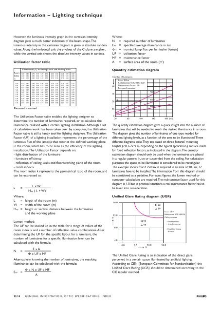
Quantity estimation diagram<br />
Number of luminaires<br />
hroom: 2.8 m<br />
Reflectances: 0.70, 0.50, 0.20<br />
60 Maintenance factor: 1.0<br />
Recessed mounted<br />
45<br />
30<br />
15<br />
750 lx<br />
500 lx<br />
300 lx<br />
0<br />
20 60 100 140<br />
2<br />
180 (m )<br />
The quantity estimation diagram gives a quick insight into the number of<br />
luminaires that will be needed to reach the desired illuminance in a room.<br />
The diagram gives the number of luminaires of one type needed for<br />
different lighting levels, as a function of the area to be illuminated.Three<br />
different diagrams exist.They are based on three fixtures' mounting<br />
heights (2.8, 6 or 9 m, depending on the typical application,) and are made<br />
for fixed reflection factors, as indicated in the diagram.The quantity<br />
estimation diagram should only be used when the luminaires are placed<br />
in a regular pattern, in, on or suspended from the ceiling. For calculation<br />
purposes the space to be illuminated is considered to be rectangular.<br />
The example shows that if 750 lux is required in an area of 100 m 2<br />
,32<br />
luminaires have to be installed.The <strong>information</strong> from this diagram should<br />
be considered as a guideline. For exact figures, the lumen method or<br />
computer calculations are required.The maintenance factor used for this<br />
diagram is 1.0 but in practical situations a real maintenance factor has to<br />
be taken into consideration.<br />
Unified Glare Rating diagram (UGR)<br />
hroom: 2.8 m<br />
Reflectances: 0.70 0.500.20<br />
Ceiling mounted<br />
: viewed endwise<br />
: viewed crosswise<br />
: Parallel to viewing<br />
direction<br />
The Unified Glare Rating is an indication of the direct glare<br />
perceived in a certain space illuminated by artificial lighting.<br />
According to CEN (European Committee for Standardisation) the<br />
Unified Glare Rating (UGR) should be determined according to the<br />
CIE tabular method.