General information, optic specifications, index
General information, optic specifications, index
General information, optic specifications, index

You also want an ePaper? Increase the reach of your titles
YUMPU automatically turns print PDFs into web optimized ePapers that Google loves.
L952D953_SRC.QXD 11-03-2004 08:19 Pagina 12.15<br />
UGR is given in 5 classes (UGR= 16, 19, 22, 25 and 28; the lower<br />
the UGR, the less direct glare is perceived from the total of the<br />
luminaires in the installation).As the CIE tabular method does not<br />
give a quick insight into the UGR characteristics of a specific<br />
installation, Philips Lighting has developed the UGR diagram.<br />
For each installation with one type of luminaire, the UGR value to<br />
be expected in the application can be determined from this diagram.<br />
Note that the UGR values are given for two viewing directions to<br />
the luminaire, endwise and crosswise, and that the UGR might vary<br />
depending on the size of the space under consideration.The highest<br />
UGR value determines the quality of the installation. In the UGR<br />
diagram the UGR is represented for the specified height and<br />
reflection factors.<br />
Visual ambience diagram<br />
g<br />
h(m) 1<br />
2<br />
3<br />
4<br />
5<br />
800 400 200 100<br />
Eh<br />
(lx)<br />
1 2 3 4 5<br />
luminaire spacing (m)<br />
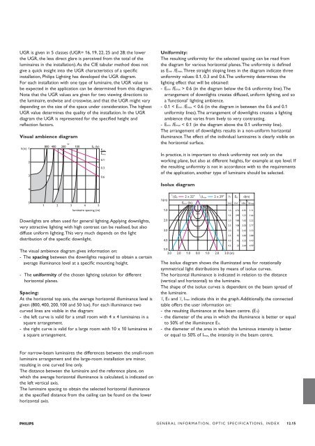
Downlights are often used for general lighting.Applying downlights,<br />
very attractive lighting with high contrast can be realised, but also<br />
diffuse uniform lighting.This very much depends on the light<br />
distribution of the specific downlight.<br />
The visual ambience diagram gives <strong>information</strong> on:<br />
- The spacing between the downlights required to obtain a certain<br />
average illuminance level at a specific mounting height.<br />
- The uniformity of the chosen lighting solution for different<br />
horizontal planes.<br />
Spacing:<br />
At the horizontal top axis, the average horizontal illuminance level is<br />
given (800, 400, 200, 100 and 50 lux). For each illuminance two<br />
curved lines are visible in the diagram:<br />
- the left curve is valid for a small room with 4 x 4 luminaires in a<br />
square arrangement.<br />
- the right curve is valid for a large room with 10 x 10 luminaires in<br />
a square arrangement.<br />
For narrow-beam luminaires the differences between the small-room<br />
luminaire arrangement and the large-room installation are minor,<br />
resulting in one curved line only.<br />
The distance between the luminaire and the reference plane, on<br />
which the average horizontal illuminance is calculated, is indicated on<br />
the left vertical axis.<br />
The luminaire spacing to obtain the selected horizontal illuminance<br />
at the specified distance from the ceiling can be found on the lower<br />
horizontal axis.<br />
Emin<br />
Emax<br />
0.1<br />
0.3<br />
0.6<br />
Uniformity:<br />
The resulting uniformity for the selected spacing can be read from<br />
the diagram for various horizontal planes.The uniformity is defined<br />
as Emin /Emax.Three straight sloping lines in the diagram indicate three<br />
uniformity values: 0.1, 0.3 and 0.6.The uniformity determines the<br />
lighting effect that will be obtained:<br />
-Emin /Emax > 0.6 (in the diagram below the 0.6 uniformity line).The<br />
arrangement of downlights creates diffused, uniform lighting, and so<br />
a ‘functional’ lighting ambience.<br />
- 0.1 < Emin /Emax < 0.6 (in the diagram in between the 0.6 and 0.1<br />
uniformity lines).The arrangement of downlights creates a lighting<br />
ambience that varies from lively to very contrasting.<br />
-Emin /Emax < 0.1 (in the diagram above the 0.1 uniformity line).<br />
The arrangement of downlights results in a non-uniform horizontal<br />
illuminance.The effect of the individual luminaires is clearly visible on<br />
the horizontal surface.<br />
In practice, it is important to check uniformity not only on the<br />
working plane, but also at different heights, for example at eye level. If<br />
the resulting uniformity is not in accordance with to the requirements<br />
of the application, another type of luminaire should be selected.<br />
Isolux diagram<br />
h(m)<br />
1<br />
/2E0<br />
o<br />
2 x 22<br />
Ehor<br />
(lx)<br />
1<br />
/ 2Imax<br />
o<br />
2 x 29 h<br />
(m)<br />
E0<br />
(lx)<br />
d(m)<br />
1 1<br />
/2E0 /2Imax<br />
1.0<br />
1.0 674 0.81 1.11<br />
500<br />
1.5 299 1.21 1.66<br />
2.0<br />
200<br />
2.0 168 1.62 2.22<br />
2.5 108 2.02 2.77<br />
3.0<br />
100<br />
3.0 75 2.42 3.33<br />
3.5 55 2.83 3.88<br />
4.0<br />
50<br />
4.0 42 3.23 4.43<br />
5.0<br />
4.5 33 3.64 4.99<br />
3.0 2.0 1.0 0.0 1.0 2.0 3.0 (m)<br />
The isolux diagram shows the illuminated area for rotationally<br />
symmetrical light distributions by means of isolux curves.<br />
The horizontal illuminance is indicated in relation to the distance<br />
(vertical and horizontal) to the luminaire.<br />
The shape of the isolux curves is dependent on the beam spread of<br />
the luminaire.<br />
1<br />
/ 2 E 0 and 1<br />
/ 2 Imax indicate this in the graph.Additionally, the connected<br />
table offers the user <strong>information</strong> on:<br />
- the resulting illuminance at the beam centre. (E 0)<br />
- the diameter of the area in which the illuminance is better or equal<br />
to 50% of the illuminance E 0.<br />
- the diameter of the area in which the luminous intensity is better<br />
or equal to 50% of Imax, the intensity in the beam centre.<br />
GENERAL INFORMATION, OPTIC SPECIFICATIONS, INDEX 12.15