General information, optic specifications, index
General information, optic specifications, index
General information, optic specifications, index

You also want an ePaper? Increase the reach of your titles
YUMPU automatically turns print PDFs into web optimized ePapers that Google loves.
L952D953_SRC.QXD 11-03-2004 08:21 Pagina 12.14<br />
Information – Lighting technique<br />
However, the luminous intensity graph in the cartesian intensity<br />
diagram gives a much better indication of the beam shape.The<br />
luminous intensity in the cartesian diagram is given in absolute candela<br />
values.Along the horizontal axis the -values of the C-plane are given,<br />
while the vertical axis shows the absolute intensity values in candela.<br />
Utilisation factor table<br />
Room<br />
Index<br />
k<br />
0.60<br />
0.80<br />
1.00<br />
1.25<br />
1.50<br />
2.00<br />
2.50<br />
3.00<br />
4.00<br />
5.00<br />
0.80<br />
0.50<br />
0.30<br />
0.43<br />
0.51<br />
0.57<br />
0.63<br />
0.67<br />
0.73<br />
0.77<br />
0.79<br />
0.82<br />
0.84<br />
0.80<br />
0.50<br />
0.10<br />
0.41<br />
0.48<br />
0.53<br />
0.58<br />
0.61<br />
0.65<br />
0.68<br />
0.69<br />
0.71<br />
0.72<br />
0.70<br />
0.50<br />
0.30<br />
0.42<br />
0.50<br />
0.56<br />
0.62<br />
0.66<br />
0.71<br />
0.75<br />
0.77<br />
0.79<br />
0.81<br />
0.70<br />
0.50<br />
0.20<br />
0.41<br />
0.49<br />
0.54<br />
0.59<br />
0.63<br />
0.68<br />
0.71<br />
0.72<br />
0.75<br />
0.76<br />
0.70<br />
0.50<br />
0.10<br />
0.40<br />
0.47<br />
0.53<br />
0.57<br />
0.60<br />
0.65<br />
0.67<br />
0.69<br />
0.70<br />
0.71<br />
0.70<br />
0.30<br />
0.10<br />
0.36<br />
0.43<br />
0.49<br />
0.54<br />
0.57<br />
0.62<br />
0.65<br />
0.67<br />
0.69<br />
0.70<br />
0.50<br />
0.30<br />
0.10<br />
0.36<br />
0.43<br />
0.48<br />
0.53<br />
0.56<br />
0.61<br />
0.64<br />
0.66<br />
0.68<br />
0.69<br />
0.50<br />
0.10<br />
0.10<br />
0.33<br />
0.40<br />
0.46<br />
0.51<br />
0.54<br />
0.60<br />
0.63<br />
0.65<br />
0.67<br />
0.68<br />
The Utilisation Factor table enables the lighting designer to<br />
determine the number of luminaires required, or to calculate the<br />
illuminance realised with a certain lighting installation.Although a lot<br />
of calculation work has been taken over by computer, the Utilisation<br />
Factor table is still a handy tool for lighting designers.The Utilisation<br />
Factor (UF) of a lighting installation represents the percentage of the<br />
luminous flux of the lamp(s) that reaches the defined working plane<br />
in the room, which has to be seen as the efficiency of the lighting<br />
installation.The Utilisation Factor depends on:<br />
- light distribution of the luminaire<br />
- luminaire efficiency<br />
- reflection of ceiling, walls and floor/working plane of the room<br />
- room <strong>index</strong> k<br />
The room <strong>index</strong> k represents the geometrical ratio of the room, and<br />
can be expressed as:<br />
0.30<br />
0.30<br />
0.10<br />
0.35<br />
0.42<br />
0.48<br />
0.53<br />
0.56<br />
0.60<br />
0.63<br />
0.65<br />
0.67<br />
0.67<br />
0.30<br />
0.10<br />
0.10<br />
0.33<br />
0.40<br />
0.45<br />
0.50<br />
0.54<br />
0.59<br />
0.62<br />
0.64<br />
0.66<br />
0.67<br />
0.00<br />
0.00<br />
0.00<br />
0.32<br />
0.39<br />
0.44<br />
0.49<br />
0.53<br />
0.58<br />
0.60<br />
0.62<br />
0.64<br />
0.65<br />
k =<br />
L x W<br />
Hwp ( L + W)<br />
Where:<br />
L = length of the room (m)<br />
W = width of the room (m)<br />
Hwp = height or vertical distance between the luminaires<br />
and the working plane<br />
Lumen method:<br />
The UF can be looked up in the table for a range of values of the<br />
room <strong>index</strong> k and a number of reflection value combinations.After<br />
determining the UF for the specific layout for a luminaire, the<br />
number of luminaires for a specific illumination level can be<br />
calculated with the formula:<br />
E x A<br />
N =<br />
x UF x MF<br />
Alternatively, knowing the number of luminaires, the resulting<br />
illuminance can be calculated with the formula:<br />
x N x UF x MF<br />
EAV =<br />
Reflectances (%) for ceilings, walls and working plane<br />
Recessed mounted<br />
A<br />
12.14 GENERAL INFORMATION, OPTIC SPECIFICATIONS, INDEX<br />
Where:<br />
N = required number of luminaires<br />
EAV = specified average illuminance in lux<br />
n = nominal lamp flux per luminaire (lumen)<br />
UF = utilisation factor<br />
MF = maintenance factor<br />
A = surface area of the room (m 2<br />
)<br />
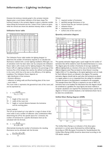
Quantity estimation diagram<br />
Number of luminaires<br />
hroom: 2.8 m<br />
Reflectances: 0.70, 0.50, 0.20<br />
60 Maintenance factor: 1.0<br />
Recessed mounted<br />
45<br />
30<br />
15<br />
750 lx<br />
500 lx<br />
300 lx<br />
0<br />
20 60 100 140<br />
2<br />
180 (m )<br />
The quantity estimation diagram gives a quick insight into the number of<br />
luminaires that will be needed to reach the desired illuminance in a room.<br />
The diagram gives the number of luminaires of one type needed for<br />
different lighting levels, as a function of the area to be illuminated.Three<br />
different diagrams exist.They are based on three fixtures' mounting<br />
heights (2.8, 6 or 9 m, depending on the typical application,) and are made<br />
for fixed reflection factors, as indicated in the diagram.The quantity<br />
estimation diagram should only be used when the luminaires are placed<br />
in a regular pattern, in, on or suspended from the ceiling. For calculation<br />
purposes the space to be illuminated is considered to be rectangular.<br />
The example shows that if 750 lux is required in an area of 100 m 2<br />
,32<br />
luminaires have to be installed.The <strong>information</strong> from this diagram should<br />
be considered as a guideline. For exact figures, the lumen method or<br />
computer calculations are required.The maintenance factor used for this<br />
diagram is 1.0 but in practical situations a real maintenance factor has to<br />
be taken into consideration.<br />
Unified Glare Rating diagram (UGR)<br />
hroom: 2.8 m<br />
Reflectances: 0.70 0.500.20<br />
Ceiling mounted<br />
: viewed endwise<br />
: viewed crosswise<br />
: Parallel to viewing<br />
direction<br />
The Unified Glare Rating is an indication of the direct glare<br />
perceived in a certain space illuminated by artificial lighting.<br />
According to CEN (European Committee for Standardisation) the<br />
Unified Glare Rating (UGR) should be determined according to the<br />
CIE tabular method.