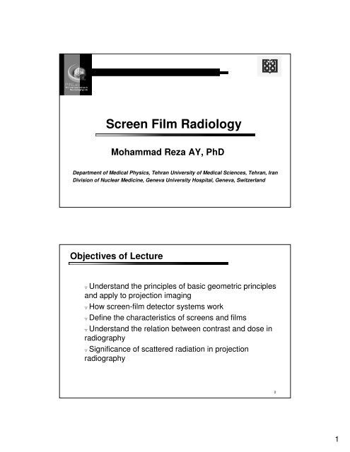
Screen Film Radiology
Screen Film Radiology
Screen Film Radiology

You also want an ePaper? Increase the reach of your titles
YUMPU automatically turns print PDFs into web optimized ePapers that Google loves.
<strong>Screen</strong> <strong>Film</strong> <strong>Radiology</strong><br />
Mohammad Reza AY, PhD<br />
Department of Medical Physics, Tehran University of Medical Sciences, Tehran, Iran<br />
Division of Nuclear Medicine, Geneva University Hospital, Geneva, Switzerland<br />
Objectives of Lecture<br />
v Understand the principles of basic geometric principles<br />
and apply to projection imaging<br />
v How screen-film detector systems work<br />
v Define the characteristics of screens and films<br />
v Understand the relation between contrast and dose in<br />
radiography<br />
v Significance of scattered radiation in projection<br />
radiography<br />
2<br />
1
1. Projection Radiography<br />
v Projection imaging is the<br />
acquisition of a 2D image of a<br />
patient’s 3D anatomy<br />
v Projection radiography is a<br />
transmission imaging<br />
procedure<br />
v The optical density at any<br />
location on the film<br />
corresponds to the<br />
attenuation characteristics (e -<br />
µx ) of the patient at that<br />
location<br />
c.f. Bushberg, et al. The Essential Physics of Medical Imaging, 2 nd ed., p 146.<br />
2. Basic Geometric Principles<br />
v Similar triangles (geometry)<br />
v a/A = b/B = c/C = h/H<br />
v d/D = e/E = f/F = g/G<br />
v Similar triangles are<br />
encountered when determining<br />
the image magnification and<br />
when evaluating image<br />
unsharpness caused by focal<br />
spot size and patient motion<br />
c.f. Bushberg, et al. The Essential Physics of Medical Imaging, 2 nd ed., p 147.<br />
3<br />
4<br />
2
2. Basic Geometric Principles<br />
v a/A = b/B = c/C = h/H<br />
v d/D = e/E = f/F = g/G<br />
v Magnification (M)<br />
v Occurs because x-ray beam<br />
diverges from focal spot to<br />
image plane<br />
v For a point source,<br />
v M = I/O = SID/SOD<br />
v largest when object closest<br />
to focal spot and<br />
approaches value of 1 when<br />
object at image plane<br />
c.f. Bushberg, et al. The Essential Physics of Medical Imaging, 2 nd ed., p 147.<br />
2. Basic Geometric Principles<br />
v For a extended source (focal spot),<br />
v Penumbra or blur (f)<br />
v edge gradient blurring due to<br />
finite size of focal spot (F)<br />
v f/F = OID/SOD<br />
v f/F = (SID-SOD)/SOD<br />
v f/F = (SID/SOD)-1<br />
v f = F(M-1)<br />
v f or blur increases with F and M<br />
v f can be decreased by keeping<br />
object close to image plane<br />
(↓OID)<br />
c.f. Bushberg, et al. The Essential Physics of<br />
Medical Imaging, 2 nd ed., p 147.<br />
5<br />
6<br />
3
3. The <strong>Screen</strong>-<strong>Film</strong> Cassette<br />
Cassette<br />
v Light-tight and ensures screen<br />
contact with film<br />
v Front surface - carbon fiber<br />
v ID flash card area on back<br />
1 or 2 Intensifying <strong>Screen</strong>s<br />
v Convert x-rays to visible light<br />
v Mounted on layers of<br />
compressed foam (produces<br />
force)<br />
Sheet of film<br />
v Register the x-ray distribution<br />
v Chemically processed<br />
v Storage and display<br />
c.f. Bushberg, et al. The Essential Physics of<br />
Medical Imaging, 2 nd ed., p 148.<br />
4. Characteristics of Intensifying <strong>Screen</strong>s<br />
v <strong>Film</strong> relatively insensitive to x-rays, requires a lot of x-ray energy to<br />
produced a properly exposed x-ray film<br />
v Patient receives a large dose<br />
v To reduce dose and exposure times, screens are used<br />
v <strong>Screen</strong>s made of scintillating material: phosphor<br />
v When x-rays interact with phosphor, visible or UV light is emitted<br />
Light emitted darkens the film<br />
v → <strong>Screen</strong>-film detectors are considered an Indirect detector<br />
Using film-screen film screen versus film only reduces<br />
radiation dose to patient by a factor of 50!<br />
7<br />
8<br />
4
4. <strong>Screen</strong> Composition and Construction<br />
v Early 20 th century: calcium<br />
tungstate, CaWO 4<br />
v Since early 70’s: rare earth<br />
phosphor<br />
v Lanthanide series: Z = 57 – 71<br />
v Gd 2 O 2 S:Tb (gadolinium<br />
oxysulfide: terbium) - common<br />
v LaOBr:Tm (lanthanum<br />
oxybromide: thulium)<br />
v YTaO 4 :Nb (yttrium tantalate:<br />
niobium) c.f. http://www.ktf- split.hr/periodni/en/<br />
4. <strong>Screen</strong> Composition and Construction<br />
v Top coat<br />
v Phosphor and binder<br />
v Adhesive<br />
v Support<br />
v Phosphor thickness (g/cm 2 )<br />
expressed as mass thickness =<br />
thickness (cm) · density (g/cm 3 )<br />
v<br />
v General radiography: each of<br />
two screens around 60 mg/cm 2<br />
v Mammography: single screen of<br />
35 mg/cm 2 used<br />
c.f. Bushberg, et al. The Essential Physics of Medical Imaging, 2 nd ed., p 150.<br />
Cross-sectional image of<br />
an intensifying screen<br />
9<br />
10<br />
5
4. Intensifying <strong>Screen</strong> Function and Geometry<br />
v Function: absorb x-rays, convert to visible or UV light which exposes the<br />
film emulsion<br />
v Conversion efficiency of a phosphor = fraction of absorbed energy<br />
emitted as UV or visible light<br />
v CaWO 4 ≈ 5% intrinsic conversion efficiency<br />
v Gd 2 O 2 S:Tb ≈ 15% intrinsic conversion efficiency<br />
50,000 eV x-ray x 0.15 = 7500 eV<br />
Green light, 2.7 eV<br />
7500 eV / 2.7 eV/photon<br />
= 2,800 photons<br />
200-1000 photons reach film after diffusing through phosphor layer<br />
and being reflected at the interface layers<br />
4. Intensifying <strong>Screen</strong> Function and Geometry<br />
v Quantum Detective Efficiency<br />
(QDE) of a screen = fraction of<br />
incident x-rays photons that<br />
interact with it<br />
v QDE increases with screen<br />
thickness<br />
c.f. Bushberg, et al. The Essential Physics of<br />
Medical Imaging, 2 nd ed., p 151.<br />
11<br />
12<br />
6
4. Intensifying <strong>Screen</strong> Function and Geometry<br />
v Thicker screens absorb greater<br />
amount of x-rays, but a greater<br />
lateral spread of the visible light<br />
occurs (isotropic diffusion) causing<br />
blurring and reducing spatial<br />
resolution<br />
v A thin screen results in less x-ray<br />
absorption but less lateral spread of<br />
light and better spatial resolution<br />
v For maximum resolution, a singlescreen<br />
cassette is used<br />
v X-rays first traverse the film and<br />
then strike screen<br />
v Less light spread and maximum<br />
spatial resolution<br />
Cross-section of a screen-film cassette<br />
↑<br />
↑<br />
Radiography Mammography<br />
c.f. Bushberg, et al. The Essential Physics of<br />
Medical Imaging, 2 nd ed., p 152.<br />
4. Intensifying <strong>Screen</strong> Function and Geometry<br />
v As screen thickness ↑ QDE ↑ and screen sensitivity ↑, but<br />
light-diffusion increases<br />
v Compromise between sensitivity and resolution<br />
c.f. http://www.sprawls.org/resources/RADDETAIL/classroom.htm c.f. http://www.rad-icon.com/pdf/Radicon_AN07.pdf<br />
13<br />
14<br />
7
4. Intensifying <strong>Screen</strong> Function and Geometry<br />
v Modulation Transfer Function<br />
(MTF) describes the resolution<br />
properties of an imaging<br />
system<br />
v The MTF illustrates the<br />
fraction (or %) of an object’s<br />
contrast that is recorded by the<br />
imaging system as a function of<br />
object size (spatial frequency)<br />
v F (linepairs or cycles/mm)<br />
F=1/2∆, ∆ = object size<br />
v As screen thickness ↑ MTF ↓<br />
c.f. Bushberg, et al. The Essential Physics of<br />
Medical Imaging, 2 nd ed., p 152.<br />
4. Intensifying <strong>Screen</strong> Function and Geometry<br />
v Crossover or print-through:<br />
light from top screen<br />
penetrates the film base and<br />
exposes the bottom emulsion<br />
or vice versa<br />
v Due to type of film grain, not a<br />
problem now<br />
c.f. http://www.sprawls.org/resources/RADDETAIL/classroom.htm<br />
15<br />
16<br />
8
4. Conversion Efficiency (CE)<br />
Total conversion efficiency (CE) of a screen-film combination<br />
refers to the ability of the screen or screens to convert the energy<br />
deposited by the absorbed x-rays into film darkening or optical<br />
density<br />
CE depends on:<br />
v Intrinsic conversion efficiency of phosphor<br />
v Efficiency of light propagation through the screen to film<br />
emulsion layer<br />
v Efficiency of the film emulsion in absorbing the emitted<br />
light<br />
c.f. Bushberg, et al. The Essential Physics of<br />
Medical Imaging, 2 nd ed., p 153.<br />
4. Conversion Efficiency (CE)<br />
Light propagation in screen (diffuses in all directions)<br />
Distance from absorption to film<br />
Light-absorbing dye reduces lateral distance: CE ↓ (slow), Spatial resolution or MTF ↑<br />
Reflective layer redirect light photons: CE ↑ (fast), Spatial resolution or MTF ↓<br />
<strong>Screen</strong> is a linear device at a given x-ray energy<br />
v Number of x-ray photons doubles, light intensity produced by screen also doubles<br />
c.f. Bushberg, et al. The Essential Physics of Medical Imaging, 2 nd ed., p 153.<br />
17<br />
18<br />
9
4. Absorption Efficiency (AE)<br />
v The absorption efficiency or<br />
QDE describes how efficiently<br />
the screen detects x-ray photons<br />
that are incident upon it<br />
v X-ray photon absorbed by the<br />
screen deposits its energy and<br />
some fraction of energy is<br />
converted to light photons<br />
v <strong>Screen</strong>-film systems are energy<br />
detectors<br />
The number of light photons<br />
produced in the screen is<br />
determined by the total<br />
amount of x-ray energy<br />
absorbed by the screen, not<br />
by the number of x-ray<br />
photons<br />
c.f. Bushberg, et al. The Essential Physics of<br />
Medical Imaging, 2 nd ed., pp. 154-155.<br />
4. Overall Efficiency of a <strong>Screen</strong>-<strong>Film</strong> System<br />
v Total efficiency = AE · CE<br />
v A SF system increases x-ray<br />
detection efficiency compared to<br />
film only (29.5% vs. 0.65% at 80<br />
kVp)<br />
v Using film-screen versus film only<br />
reduces radiation dose to patient by<br />
a factor of 50!<br />
v Intensification factor (IF) = ratio of<br />
energy absorption of 120 mg/cm 2<br />
phosphor vs. 0.80 mg/cm 2 AgBr<br />
v An IF of 50 is achieved for Gd2O2S over the x-ray<br />
energy spectra commonly used for diagnostic<br />
examination<br />
c.f. Bushberg, et al. The Essential Physics of<br />
Medical Imaging, 2 nd ed., p. 156.<br />
19<br />
20<br />
10
4. Noise Effects of Changing CE vs. AE<br />
Noise: local variations in film OD, not representing variations of<br />
attenuation in patient<br />
Includes random noise caused by factors such as<br />
v Statistical fluctuation in x-ray quantity interacting with<br />
screens<br />
v Statistical fluctuation in fraction of light emitted by the<br />
screen that is absorbed by the film emulsion<br />
v Statistical fluctuation in the distribution of silver halide<br />
grains in film emulsion<br />
The visual perception of noise is reduced (better image quality)<br />
when the number of detected x-ray photons increases (more in<br />
Chapter 10)<br />
Noise Effects on Image Quality<br />
c.f. http://www.sprawls.org/resources/IMGCHAR/module/#20<br />
21<br />
22<br />
11
4. Noise Effects of Changing CE vs. AE<br />
What happens to noise in image when the CE is increased<br />
(or fast film screen system) by adding reflective layer?<br />
If “speed” of the SF system is increased by increasing the CE<br />
(so that each detected x-ray photon becomes more efficient<br />
at darkening the film):<br />
v few x-ray photons are required to achieve same film<br />
darkening (as before increasing CE), so noise increases<br />
v Therefore, increasing the CE to increase the speed of a SF<br />
system will increase the noise in the images<br />
4. Noise Effects of Changing CE vs. AE<br />
What happens to noise in image when the AE is<br />
increased (thicker screen)?<br />
If AE is increased, 10% more x-ray photons detected, then<br />
reduction of 10% in incident x-ray beam is required to<br />
deliver same amount of film darkening (as before<br />
increasing AE)<br />
v Since the fraction of increase in x-ray photon detection and<br />
reduction in incident x-ray intensity is same, the total<br />
number of detected x-ray photons is the same. No change<br />
in noise<br />
v However, spatial resolution will get worse with thicker<br />
screens<br />
23<br />
24<br />
12
5. Characteristics of <strong>Film</strong><br />
v 1 or 2 layers of film emulsion<br />
coated onto a flexible Mylar plastic<br />
sheet<br />
v Emulsion: silver halide (AgBr and<br />
AgI) bound in a gelatin base<br />
v Emulsion of an exposed sheet of<br />
film contains the latent image<br />
v Latent image rendered visible<br />
through film processing by<br />
chemical reduction of silver halide<br />
into metallic silver grains<br />
Optical Density<br />
Tubular<br />
grains<br />
c.f. Bushberg, et al. The Essential Physics of<br />
Medical Imaging, 2 nd ed., p. 157.<br />
v Increased x-ray exposure → developed film<br />
becomes darker<br />
Cubic<br />
grains<br />
v Degree of darkness of the film is quantified by the<br />
optical density (OD) which is measured with a<br />
densitometer<br />
v Transmittance (T) is the fraction of incident light<br />
passing through the film<br />
v T = I/I 0 where I – intensity measured at a particular<br />
location on film and I 0 – intensity of light measured<br />
with no film in densitometer<br />
c.f. Bushberg, et al. The Essential Physics of<br />
Medical Imaging, 2nd ed., p. 158.<br />
25<br />
26<br />
13
Optical Density<br />
v OD = -log 10 (T) = log 10 (1/T) = log 10 (I 0 /I), inverse relationship is T<br />
= 10 -OD<br />
v As OD increases, transmittance decreases<br />
v The OD of superimposed films is additive<br />
c.f. Bushberg, et al. The Essential Physics of<br />
Medical Imaging, 2nd ed., p. 158.<br />
The Hurter and Driffield (H&D) Curve<br />
v H&D (characteristic) curve<br />
describes how film responds to<br />
x-ray exposure<br />
v Non-linear, sigmoidal shape<br />
v log 10 -log 10 plot (OD vs. log<br />
relative exposure)<br />
v <strong>Film</strong> base → OD = 0.11 – 0.15<br />
c.f. Bushberg, et al. The Essential Physics of<br />
Medical Imaging, 2 nd ed., p. 159.<br />
27<br />
28<br />
14
The Hurter and Driffield (H&D) Curve<br />
v Fogging due to long storage,<br />
heat and low background<br />
exposure<br />
v Base + Fog ≤ 0.20 OD<br />
v Toe<br />
v Linear region<br />
v Shoulder<br />
c.f. Bushberg, et al. The Essential Physics of<br />
Medical Imaging, 2 nd ed., p. 159.<br />
Contrast of <strong>Film</strong> (Average Gradient)<br />
v Contrast of film is related to<br />
the slope of the H&D curve:<br />
v Higher slope have higher<br />
contrast<br />
v Reduced slope have<br />
lower contrast<br />
v Overall contrast given by<br />
Average gradient =<br />
v [OD 2 -OD 1 ]/[log 10 (E 2 )log<br />
10 (E 1 )]<br />
v OD 2 = 2.0 + B + F<br />
v OD 1 = 0.25 + B + F<br />
v Range from 2.5 – 3.5 c.f. Bushberg, et al. The Essential Physics of<br />
Medical Imaging, 2 nd ed., pp. 160.<br />
30<br />
29<br />
15
Contrast of <strong>Film</strong> (Average Gradient)<br />
v Describes the contrast properties of the film-screen system<br />
v Important to obtain well controlled exposure levels to ensure<br />
good contrast<br />
v <strong>Film</strong> manufacturer physically controls contrast on film by<br />
varying the size distribution of the sliver grains<br />
c.f. Bushberg, et al. The Essential Physics of Medical Imaging, 2 nd ed., pp. 161.<br />
Sensitivity or Speed<br />
v As the speed of SF system<br />
increases, the amount of x-ray<br />
exposure required to achieve<br />
same OD decreases<br />
v Fast films requires less<br />
exposure to achieve a given OD;<br />
slow films require more<br />
exposure<br />
v Faster (higher-speed) SF<br />
systems result in lower patient<br />
doses but in general exhibit<br />
more quantum mottle (noise)<br />
than slower systems<br />
c.f. Bushberg, et al. The Essential Physics of<br />
Medical Imaging, 2 nd ed., p. 162.<br />
31<br />
32<br />
16
Sensitivity or Speed<br />
v Absolute speed = 1 / Exposure<br />
(R) required to achieve OD = 1.0 +<br />
B + F<br />
v Relative speed of a SF<br />
combination– relative to a common<br />
standard (100 speed),<br />
commercially used<br />
v Most US institutions that use<br />
screen-film use 400 speed for<br />
general radiography<br />
Sensitivity or Speed<br />
v 100-speed – detail work<br />
bony radiographs of<br />
extremities, (thinner screens,<br />
slower, better spatial<br />
resolution)<br />
v 600-speed – angiography<br />
(thicker screens, decreased<br />
spatial resolution)<br />
c.f. Bushberg, et al. The Essential Physics of<br />
Medical Imaging, 2 nd ed., p. 162.<br />
c.f. Bushberg, et al. The Essential Physics of<br />
Medical Imaging, 2 nd ed., p. 162.<br />
33<br />
34<br />
17
Latitude (Dynamic Range)<br />
v Horizontal shift between 2<br />
H&D curves – systems differ<br />
in speed<br />
v Systems with different<br />
contrast have H&D curves<br />
with different slopes<br />
v Latitude is the range of xray<br />
exposures that deliver<br />
ODs in the usable range<br />
v Latitude is also called<br />
dynamic range c.f. Bushberg, et al. The Essential Physics of<br />
Medical Imaging, 2 nd ed., p. 162.<br />
Latitude (Dynamic Range)<br />
v System A has higher<br />
contrast but reduced latitude<br />
v It is more difficult to<br />
consistently achieve proper<br />
exposures with low-latitude<br />
SF systems.<br />
v Chest radiography needs a<br />
high-latitude system to<br />
achieve adequate contrast in<br />
both the mediastinum and<br />
lung fields<br />
c.f. Bushberg, et al. The Essential Physics of<br />
Medical Imaging, 2 nd ed., p. 162.<br />
35<br />
36<br />
18
6. The <strong>Screen</strong>-<strong>Film</strong> System<br />
v <strong>Film</strong> emulsion should be sensitive to light emitted<br />
by screen<br />
v CaWO 4 emits blue light to which film is sensitive<br />
v Gd 2 O 2 S:Tb emits green light<br />
v Wavelength sensitizers added to film<br />
v <strong>Screen</strong>s and films usually purchased in<br />
combination since matching of spectral sensitivity<br />
very important<br />
Reciprocity Law of <strong>Film</strong><br />
v Reciprocity law of film states that<br />
the relationship between exposure<br />
and OD should remain constant<br />
regardless of the exposure rate<br />
v Reciprocity law failure: at long<br />
and short exposure times, the film<br />
becomes less efficient at using the<br />
light incident on it and lower ODs<br />
result<br />
v This is a factor in mammography<br />
when long exposure times are<br />
needed for large and dense<br />
breasts<br />
c.f. Bushberg, et al. The Essential Physics of Medical Imaging, 2 st ed., p. 163.<br />
All points exposed exactly the same with different<br />
exposure rate<br />
37<br />
38<br />
19
7. Contrast and Dose in Radiography<br />
v The SF system governs the overall detector contrast<br />
v The contrast of a specific radiographic study depends on the<br />
requirements of the study, total exposure time, radiation dose, size of<br />
patient and so on…<br />
v The kVp (quality) and mAs (quantity) are adjusted by the<br />
technologist to adjust the subject contrast<br />
v Quality – energy or penetrating power of x-ray beam (As kVp<br />
increases, HVL also increases)<br />
v Quantity – number of x-ray photons<br />
Technique still an art, but:<br />
v Technique chart<br />
v Phototimer (automatic technique)<br />
c.f. Bushberg, et al. The Essential Physics of Medical Imaging, 2 nd ed., pp. 165.<br />
Contrast and Dose in Radiography (2)<br />
v kVp ↑ → dose and contrast ↓<br />
v Classic compromise between image contrast and patient<br />
dose<br />
c.f. Bushberg, et al. The Essential Physics of<br />
Medical Imaging, 2 nd ed., pp. 165-166.<br />
39<br />
40<br />
20
8. Scattered Radiation in Projection Radiography<br />
v Most radiographic interactions<br />
produce scattered photons<br />
v Scattered photons → violation of<br />
the basic principle of projection<br />
imaging: mis-information reducing<br />
contrast<br />
v The scattered photon if detected<br />
by film causes film darkening but<br />
provides no useful information to<br />
the image<br />
v Scatter-to-primary (S/P) ratio<br />
refers to how many scattered xray<br />
photons there are for every<br />
primary photon<br />
c.f. Bushberg, et al. The Essential Physics of<br />
Medical Imaging, 2 nd ed., p. 167.<br />
Scattered Radiation in Projection Radiography<br />
Scatter-to-Primary ratio (S/P)<br />
v Area of collimated x-ray<br />
field<br />
v Object thickness<br />
v kVp of x-ray beam<br />
v As FOV is reduced, scatter<br />
is reduced<br />
c.f. Bushberg, et al. The Essential Physics of<br />
Medical Imaging, 2 nd ed., p. 167.<br />
41<br />
42<br />
21
Scattered Radiation in Projection Radiography<br />
v Scatter radiation causes loss<br />
of contrast<br />
v In the absence of scatter, for<br />
two adjacent areas<br />
transmitting photon fluences<br />
of A and B, the contrast is:<br />
v C 0 = [A-B]/A<br />
v In the presence of scatter:<br />
v C = C 0 x [1 / (1 + S/P)]<br />
v S/P ↑ → contrast ↓<br />
v 1/(1+S/P): contrast reduction<br />
factor c.f. Bushberg, et al. The Essential Physics of<br />
Medical Imaging, 2 nd ed., p. 168.<br />
The Antiscatter Grid<br />
v The antiscatter grid is used to combat<br />
the effects of scatter<br />
v Between object and detector<br />
v Uses geometry to ↓ scatter<br />
v Thin lead septa separated by aluminum<br />
or carbon fiber, aligned with focal spot<br />
v Grid ratio (GR) = H/W = septa<br />
height/interspace width<br />
v 8:1, 10:1 and 12:1 common, 5:1 for<br />
mammography<br />
v ↑ GR → ↓ S/P<br />
v ↑ GR → ↑ dose<br />
c.f. Bushberg, et al. The Essential Physics of Medical Imaging, 2 nd ed., pp. 168-169.<br />
43<br />
44<br />
22
The Antiscatter Grid<br />
v ↑ GR → ↑ clean-up of<br />
scatter striking the grid at<br />
large angles, less effective<br />
for smaller angles<br />
v<br />
v Grid frequency: lines/cm<br />
grid freq. doesn’t alter S/P<br />
60 lines/cm<br />
The Antiscatter Grid<br />
v Stationary grids: lines<br />
appear on image<br />
v Bucky: device that moves<br />
grid<br />
v Moving grid bars on visible<br />
on image<br />
v Bucky factor =<br />
v dose w grid /dose w/o grid<br />
v Bucky factors:<br />
v Range from 3 to 5<br />
c.f. Bushberg, et al. The Essential Physics of<br />
Medical Imaging, 2 nd ed., pp. 170.<br />
c.f. Bushberg, et al. The Essential Physics of<br />
Medical Imaging, 2 nd ed., pp. 171.<br />
45<br />
46<br />
23
Grid Artifacts<br />
v Most grid artifacts due to<br />
mispositioning<br />
v Upside down: severe loss of<br />
OD at margins<br />
v Crooked & off-center:<br />
general decrease of OD<br />
across entire image<br />
v Off-focus: loss at lateral<br />
edges<br />
c.f. Bushberg, et al. The Essential Physics of Medical Imaging, 2 nd ed., pp. 172.<br />
Air Gaps<br />
v Air gap: ↓ S/P, but ↑ M, ↓<br />
FOV and ↓ MTF (unless very<br />
small focal spot used)<br />
v Not used all that often in<br />
radiography except chest<br />
radiography, used in<br />
mammography<br />
c.f. Bushberg, et al. The Essential Physics of<br />
Medical Imaging, 2 nd ed., pp. 173.<br />
47<br />
48<br />
24
IMAGE QUALITY<br />
INFLUENCE OF ENERGY (kV)<br />
Bone Soft tissue<br />
THE CORRECT ENERGY<br />
Good difference between dense and soft tissues<br />
Best contrast<br />
TOO HIGH ENERGY<br />
Very few photons are absorbed<br />
Small difference between dense and soft tissues<br />
Low contrast<br />
TOO LOW ENERGY<br />
Most of the photons are absorbed<br />
Low signal<br />
Dose to the patient with no usable output<br />
• High energy may be necessary in dense or thick areas (abdomen, pelvis)<br />
• Very low energies are rarely of use and are harmful to the patient<br />
25
INFLUENCE OF ENERGY (kV)<br />
kV<br />
High<br />
Low<br />
Low<br />
Loss of contrast<br />
Pale image<br />
Lack of photons<br />
going through<br />
Pale and loss of<br />
information<br />
High<br />
INFLUENCE OF ENERGY (kV)<br />
Patient dose<br />
Penetration<br />
Contrast<br />
Loss of contrast<br />
Dark image<br />
High contrast<br />
Dark image<br />
The choice of kV depends on the patient anatomy and the object to be imaged<br />
• Thick or dense part of the body: High kV,<br />
ex. Abdomen, pelvis - 80 to 100 kV<br />
• Small or flat parts of the body: Low kV,<br />
ex. Breast, hand - 30 to 50 kV<br />
Low kV High kV<br />
Then the necessary mAs is elected to produce the clinically useful image<br />
mAs<br />
26
INFLUENCE OF FOCAL SPOT SIZE: PENUMBRA<br />
Dark Clear Dark<br />
Dark<br />
Gray<br />
Clear<br />
Penumbra<br />
Fine (small) focal spot<br />
Large focal spot<br />
Gray<br />
Dark<br />
Sharp projection from a fine focal<br />
spot<br />
Large focal spot is<br />
responsible for blurr,<br />
leading to inability to<br />
distinguish between<br />
small, close objects<br />
LOSS OF SPATIAL RESOLUTION<br />
INFLUENCE OF FOCAL SPOT SIZE: PENUMBRA<br />
SOD<br />
OID<br />
SID<br />
Increased<br />
SOD<br />
The blurr effect, or Penumbra, can be decreased by:<br />
• Increasing the Source to Object Distance<br />
• Placing the image receptor as close as possible to the patient<br />
Decreased<br />
OID<br />
27
MAGNIFICATION EFFECT<br />
long OID<br />
short OID<br />
There is always a magnification, but the same object may appear with different size<br />
depending on its location in the body<br />
The differential magnification is also reduced by using long SOD<br />
and image receptor close to the patient<br />
SIGNAL TO NOISE RATIO (SNR)<br />
Less<br />
Noise<br />
SNR =<br />
IMPROVING SNR<br />
Signal<br />
Inherent object contrast<br />
Amplitude of the signal (difference in contrast versus the local background)<br />
Amplitude of the noise (random fluctuation of the signal)<br />
The better the SNR<br />
The better the visibility<br />
LOSS OF CONTRAST<br />
RESOLUTION<br />
28
INCREASING THE SIGNAL - CONTRAST AGENTS<br />
A way to improve SNR<br />
Injection of an Iodine<br />
solution in the antecubital<br />
vein (arm)<br />
Local injection<br />
of Iodine<br />
through a<br />
catheter<br />
Early phase:<br />
opacification of the<br />
general arterial<br />
system<br />
Latter phase:<br />
opacification of the<br />
urinary system<br />
(IVU)<br />
Local vascular<br />
opacification:<br />
here the<br />
coronary arteries<br />
Catheter<br />
Thanks For Your Attention<br />
29