Packet Queueing Delay in Resilient Packet Ring Network Nodes
Packet Queueing Delay in Resilient Packet Ring Network Nodes
Packet Queueing Delay in Resilient Packet Ring Network Nodes
Create successful ePaper yourself
Turn your PDF publications into a flip-book with our unique Google optimized e-Paper software.
408 Ts<strong>in</strong>ghua Science and Technology, August 2004, 9(4): 406–409<br />
For the second priority class, the queue<strong>in</strong>g delay W2<br />
has a similar expression as W1 except that an additional<br />
queue<strong>in</strong>g delay has to be counted due to higher priority<br />
customers arriv<strong>in</strong>g while a lower priority customer is<br />
wait<strong>in</strong>g <strong>in</strong> the queue. W2 is obta<strong>in</strong>ed,<br />
R+ ρ1W1<br />
W2<br />
= (3)<br />
1−ρ−ρ<br />
1 2<br />
The derivation is similar for all priority classes (k>1),<br />
and the formula for the wait<strong>in</strong>g time <strong>in</strong> the schedul<strong>in</strong>g<br />
buffer is<br />
R<br />
Wk= , k > 1<br />
1−ρ −L−ρ 1−ρ<br />
−L−ρ ( )( )<br />
1 k−1 1<br />
k<br />
(4)<br />
Suppose that all nodes have the same transmission<br />
pattern. The average number of transit buffers traversed<br />
by each packet is then obta<strong>in</strong>ed,<br />
α<br />
N −1<br />
= ∑ q ( j−1)<br />
j=<br />
2<br />
j<br />
(5)<br />
where N is the number of the nodes on the r<strong>in</strong>g, and qj<br />
is the probability of node i transmitt<strong>in</strong>g packets to its jth<br />
neighbor node.<br />
Assume that traffic of all priorities has the same arrival<br />
rate <strong>in</strong> the transmit buffer. The relationship between<br />
the traffic arrival rates <strong>in</strong> the transit buffer and<br />
<strong>in</strong> the transmit buffer is [9]<br />
λTB = αλTx<br />
(6)<br />
We assume that all packets have the same service<br />
time X . The relationship between the system utilization<br />
and the arrival rate for each priority class <strong>in</strong> a node<br />
is then<br />
ρ1 = αρA<br />
(7)<br />
For a DQ r<strong>in</strong>g, we identify five priority traffic<br />
classes as shown <strong>in</strong> Fig. 3. Us<strong>in</strong>g Eqs. (6) and (7), the<br />
system utilization of each priority class can be expressed<br />
as:<br />
ρ1 = αρA<br />
(8)<br />
ρ = ρ<br />
(9)<br />
2 A<br />
3 = B<br />
ρ ρ<br />
4 C<br />
5 ( B C)<br />
(10)<br />
ρ = ρ<br />
(11)<br />
ρ = α ρ + ρ<br />
(12)<br />
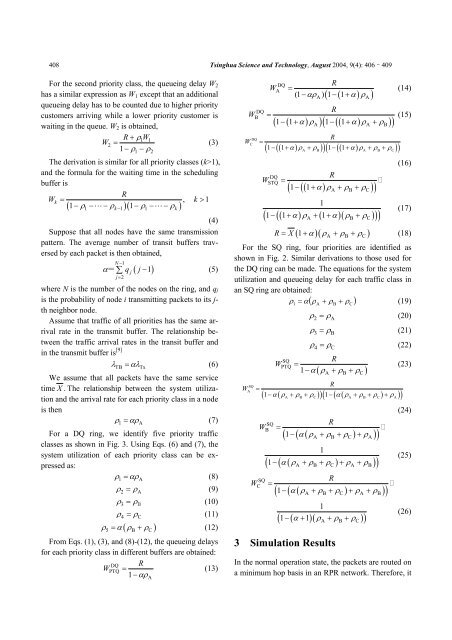
From Eqs. (1), (3), and (8)-(12), the queue<strong>in</strong>g delays<br />
for each priority class <strong>in</strong> different buffers are obta<strong>in</strong>ed:<br />
DQ R<br />
WPTQ<br />
= (13)<br />
1−<br />
αρ<br />
A<br />
W<br />
W<br />
DQ<br />
B<br />
DQ<br />
C<br />
=<br />
=<br />
W<br />
DQ<br />
A<br />
=<br />
R<br />
(1 −αρ ) 1 − 1 + α ρ<br />
( ( ) )<br />
A A<br />
R<br />
( )<br />
( 1− ( 1+ α) ρA) 1− ( ( 1+<br />
α) ρA + ρB)<br />
R<br />
( 1− ( ( 1+ α) ρA + ρB) ) 1− ( ( 1+<br />
α) ρA + ρB + ρC)<br />
W<br />
DQ<br />
STQ<br />
=<br />
( )<br />
R<br />
( 1− ( ( 1+<br />
α) ρA + ρB + ρC)<br />
)<br />
1<br />
( 1− ( ( 1+ α) ρA + ( 1+<br />
α)( ρB + ρC)<br />
) )<br />
( 1 )( )<br />
A B C<br />
(14)<br />
(15)<br />
(16)<br />
(17)<br />
R = X + α ρ + ρ + ρ (18)<br />
For the SQ r<strong>in</strong>g, four priorities are identified as<br />
shown <strong>in</strong> Fig. 2. Similar derivations to those used for<br />
the DQ r<strong>in</strong>g can be made. The equations for the system<br />
utilization and queue<strong>in</strong>g delay for each traffic class <strong>in</strong><br />
an SQ r<strong>in</strong>g are obta<strong>in</strong>ed:<br />
ρ = α ρ + ρ + ρ<br />
(19)<br />
W<br />
SQ<br />
A<br />
W<br />
=<br />
W<br />
SQ<br />
PTQ<br />
1<br />
( )<br />
A<br />
B<br />
C<br />
ρ2 = ρA<br />
(20)<br />
ρ3 = ρB<br />
(21)<br />
ρ4 = ρC<br />
(22)<br />
R<br />
=<br />
1−<br />
α ρ + ρ + ρ<br />
( )<br />
A B C<br />
R<br />
( )<br />
( 1− α( ρA + ρB + ρC) ) 1−<br />
( α( ρA + ρB + ρC) + ρA)<br />
W<br />
SQ<br />
C<br />
SQ<br />
B<br />
=<br />
R<br />
( 1−<br />
( α( ρA + ρB + ρC) + ρA)<br />
)<br />
1<br />
( 1− ( α( ρA + ρB + ρC) + ρA + ρB)<br />
)<br />
=<br />
R<br />
( 1−<br />
( α( ρA + ρB + ρC) + ρA + ρB)<br />
)<br />
1<br />
( 1− ( α + 1)(<br />
ρA + ρB + ρC)<br />
)<br />
3 Simulation Results<br />
(23)<br />
(24)<br />
(25)<br />
(26)<br />
In the normal operation state, the packets are routed on<br />
a m<strong>in</strong>imum hop basis <strong>in</strong> an RPR network. Therefore, it


