AP2003 / AX2002
AP2003 / AX2002
AP2003 / AX2002

You also want an ePaper? Increase the reach of your titles
YUMPU automatically turns print PDFs into web optimized ePapers that Google loves.
CONNECTIONS<br />
AEbus extender<br />
(optional)<br />
AEbus<br />
Peripherals<br />
Supply IN<br />
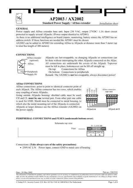
<strong>AP2003</strong> / <strong>AX2002</strong><br />
Standard Power Supply / AEbus extender<br />
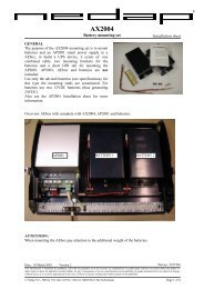
GENERAL<br />
Power supply and AEbus extender base unit. Input 230 VAC, output 27VDC/ 1.3A short circuit<br />
protected to supply several AEpacks. (Power output identical to AP2001)<br />
As there is no additional intelligence on board (inputs, monitoring, battery status) the <strong>AP2003</strong> has no<br />
address switch. If those functions are needed the AP2001 must be chosen.<br />
<strong>AX2002</strong> can be added in <strong>AP2003</strong> for extending AEbus to AEpacks at distance more than 5 meter (up<br />
to total bus length of 300 meters)<br />
AEpacks are hot-swappable, so changing AEpacks or connections can<br />
be done without interrupting the other AEpacks connected on the AEpu.<br />
All connections are underneath the covers of the AEpack. Topcover<br />
must be left in place, bottomcover can be lift off straight up.<br />
On top: Connections for AEbus<br />
On bottom: Connections to peripherials<br />
Remark: The <strong>AX2002</strong> is not hot-swappable, always disconnect power!<br />
AEbus CONNECTIONS<br />
AEbus connections: point to point to identical connector point of<br />
each AEpack. The AEbus connector has two rows, which enables<br />
easy coupling of more AEpacks.<br />
Going outside AEpacks housing: shielded cable must be used;<br />
CH and CL must be one twisted pair. From other pair one cable<br />
is used for GND. Shield must be connected to metal housing, to<br />
which also the metal mounting rail of the AEpacks is connected.<br />
AEpacks at larger distance use the AEbus extender (<strong>AX2002</strong>) on<br />
the power supply.<br />
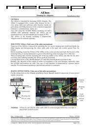
PERIPHERAL CONNECTIONS and FUSES (underneath bottom cover)<br />
Schematic top view<br />
Connections: (Take always care of the safety precautions)<br />
• 230VAC L/N Power input, connect GND to metal case of housing<br />
VIN<br />
GND<br />
CH<br />
CL<br />
GND<br />
Installation sheet<br />
AEbus connectors<br />
rear view<br />
AEpack n AEpack n+1<br />
F1 3,15A SB<br />
230VAC 230VAC<br />
L N<br />
Date : 24 May 2002<br />
Part.no.: 5261910<br />
This information is furnished for guidance, and with no guarantee as to its accuracy or completeness; its publication conveys no licence under any patent or other<br />
right, nor does the publisher assume liability for any consequence of its use; specifications and availability of goods mentioned in it are subject to change without<br />
notice; it is not to be reproduced in any way, in whole or in part, without the written consent of the publisher.<br />
Fuse<br />
© Nedap N.V., Security Control P.O. Box 103 NL-7140 AC GROENLO The Netherlands Page 1 of 4<br />
®
<strong>AP2003</strong> / <strong>AX2002</strong><br />
SAFETY PRECAUTIONS<br />
Following safety precautions must be observed during normal use, service and repair:<br />
• Always disconnect AC mains- and DC (emergency) supply before adding or replacing the<br />
<strong>AX2002</strong>.<br />
• The <strong>AP2003</strong> must be connected with safety ground (GND to metal case to which also the<br />
metal mounting rail of the AEpack is connected). If no metal housing is used, the mounting<br />
rail must be connected with safety ground.<br />
• Always disconnect from mains power supply before removing one of the covers<br />
• The <strong>AP2003</strong> may only be installed and serviced by qualified personnel<br />
• To be sure of safety, do not modify or add anything to the AEpacks other than mentioned in<br />
this installation guide or indicated by NEDAP N.V.<br />
• If the main fuse is blown, it is essential first to find the cause and make repairs before<br />
replacing the fuse.<br />
• Replace fuses only with the same type and rating.<br />
LED INDICATORS<br />
POWER (green)<br />
ON Power present<br />
POWER OUTPUT STATUS<br />
POK Power output correct<br />
ADDRESS SETTING / JUMPER SETTINGS / LOCAL TESTING (ALT MODE)<br />
Not available on the <strong>AP2003</strong>.<br />
© Nedap N.V. <strong>AP2003</strong> / <strong>AX2002</strong> Installation sheet Page 2 of 4
<strong>AP2003</strong> / <strong>AX2002</strong><br />
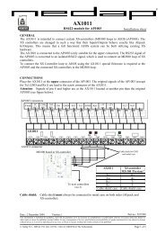
TYPICAL CONFIGURATION<br />
AEpacks can be connected to the <strong>AP2003</strong> (AP2001) for the supply of power and communication bus<br />
(extended AEbus). Also an AP8001 (AEpu) is needed for data handling and connection to the<br />
AEserver.<br />
All AEpacks are connected to each other using the AEbus with the interlinking connector at the upper<br />
side of each AEpack.<br />
Ethernet<br />
to AEserver<br />
AEbus<br />
230 VAC<br />
Door and<br />
antenna<br />
CALCULATION MODEL MAXIMUM POWERLOAD<br />
More than one AEpack can be connected to the power AEpack. For the calculation of the total power<br />
consumption add the internal power<br />
consumption of each individual AEpack<br />
and the load it’s load from external<br />
devices (e.g. lock).<br />
Door and<br />
antenna<br />
With the diagram beside the total load<br />
for an AP2001 can be calculated. If the<br />
total load exceeds the 1.3A an extra<br />
AP2001 must be added.<br />
The used AEpacks are in italic. For the<br />
12VDC output a correction factor of 0,65<br />
is used to get the correct load for 27VDC<br />
(AEbus power).<br />
In this example total load is 2230mA, so<br />
two AP2001’s (<strong>AP2003</strong>’s) are needed.<br />
Extended AEbus<br />
230 VAC<br />
Door and<br />
antenna<br />
USING MORE THAN ONE POWER SUPPLY<br />
If more than one power AEpack is needed (and AEbus is not longer than 5 meters, otherwise <strong>AX2002</strong><br />
must be used), connect only CH, CL and GND signals to AEbus connector (don’t connect VIN and<br />
GND). CH and CL must be one twisted pair. From other pair one cable is used for GND.<br />
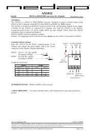
EXTENDED AEBUS: <strong>AX2002</strong> (optional)<br />
If the AEbus exceeds 5 meters, the <strong>AX2002</strong> board must be installed in the AP2001 on both sides (see<br />
also above figure). The total length of the AEbus if <strong>AX2002</strong>’s are used is 300 meters. Installation of<br />
the <strong>AX2002</strong> will be at factory. In those case where the <strong>AX2002</strong> must be installed in the AP2001<br />
always take care of the safety precautions.<br />
Attention: set switch at backside of the <strong>AX2002</strong> to the correct position: Switch selects terminating<br />
resistor needed for correct communication:<br />
First and last <strong>AX2002</strong> of the extended AEbus: switch to IN-side (towards connector)<br />
All other <strong>AX2002</strong>’s: switch to OUT-side<br />
Remark: <strong>AX2002</strong>’s must always be connected to other <strong>AX2002</strong>’s, so never to the AEbus connector.<br />
© Nedap N.V. <strong>AP2003</strong> / <strong>AX2002</strong> Installation sheet Page 3 of 4<br />
AEbus<br />
Example:<br />
Total 3 readers on one<br />
AEpu and 2 power<br />
supplies<br />
AEpack Internal Load on output (mA)<br />
load (mA) 24VDC 12VDC (0.65x)<br />
Total load<br />
(mA)<br />
AP1001 150 200 x 0,65 = 130 280<br />
AP1002 250<br />
AP1003 120 500 x 0,65 = 325 445<br />
AP1003 120 300 420<br />
AP1005 250<br />
AP1007 300 ??<br />
AP1009 200<br />
AP3002 50 100 150<br />
AP3002 50 250 300<br />
AP3003<br />
AP3004 125 200 325<br />
AP8001 300 300<br />
Total load on 27VDC (AEbus power) 2220
EXTENDED AEBUS CONNECTIONS (<strong>AX2002</strong>)<br />
The connector for the extended AEbus is<br />
located above the AEbus connector. Only the<br />
communication is extended, not the power<br />
supply (this is achieved from the Power AEpack<br />
on which the <strong>AX2002</strong> is installed).<br />
Using 2 x 2 x 0,50 mm² shielded cable means<br />
that CH and CL must be one twisted pair.<br />
From the other pair only one cable is connected<br />
to GND. The cable shield must be connected to<br />
the housing of the AEbox.<br />
<strong>AP2003</strong> / <strong>AX2002</strong><br />
SPECIFICATIONS <strong>AP2003</strong> (Product nr. 9839720)<br />
Dimensions: 230 x 126 x 70 mm (excluding mounting rail) Weight: ± 600 gr<br />
Output: AEbus power: 27 VDC, max 1,3 A<br />
Environment: Temperature: Operating: 0 – 55 °C, Storage: -30 – 65 °C Relative humidity: 10 – 93% non condensing<br />
Power: 230 – 240 VAC (-10%+6%) 50/60 Hz, (max 0,42 Amp at 230 VAC)<br />
Safety: Class I<br />
CABLE SPECIFICATIONS<br />
230 VAC Power: 3 x 0,75mm², due to local restrictions, must have earth connection<br />
FUSES<br />
230 VAC F1 3,15A SB<br />
Resistor ON for<br />
first and last<br />
<strong>AX2002</strong><br />
<strong>AX2002</strong> first <strong>AX2002</strong> n+1 <strong>AX2002</strong> last<br />
CH<br />
CL<br />
GND<br />
Resistor OFF for<br />
all <strong>AX2002</strong>’s<br />
between<br />
AEbus extender connectors<br />
rear view<br />
It is not allowed to make a STAR connection. The extended AEbus (and also the AEbus) may only be<br />
connected in LINE.<br />
FIRMWARE<br />
Pay attention that the firmware loaded in AEpack and AEpu determines functionality and protocols.<br />
SPECIFICATIONS <strong>AX2002</strong> (Product nr. 7818386)<br />
Dimensions: Fits into Power AEpack (e.g. AP2001 / <strong>AP2003</strong>)<br />
Extended AEbus: AEbus communication, no power<br />
Environment: Temperature: Operating: 0 – 55 °C, Storage: -30 – 65 °C Relative humidity: 10 – 93% non condensing<br />
CABLE SPECIFICATIONS<br />
Extended AEbus: 2 x 2 x 0,50mm² shielded, total length extended AEbus: max 300 meter (CH and CL must be twisted)<br />
MORE INFORMATION: For more detailed information contact your local Nedap supplier or check the internet site.<br />
Resistor ON for<br />
first and last<br />
<strong>AX2002</strong><br />
© Nedap N.V. <strong>AP2003</strong> / <strong>AX2002</strong> Installation sheet Page 4 of 4