Master's Thesis - Computer Graphics and Visualization - TU Delft
Master's Thesis - Computer Graphics and Visualization - TU Delft
Master's Thesis - Computer Graphics and Visualization - TU Delft

You also want an ePaper? Increase the reach of your titles
YUMPU automatically turns print PDFs into web optimized ePapers that Google loves.
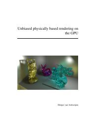
A Graphical Programming Environment<br />
for Culgi<br />
Master’s <strong>Thesis</strong><br />
1189662<br />
Ruixin Wang<br />
July 2005
<strong>TU</strong> <strong>Delft</strong><br />
Faculty EEMCS<br />
<strong>Computer</strong> <strong>Graphics</strong> & CAD CAM<br />
Leiden University<br />
Gorlaeus Laboratories<br />
Soft Condensed Matter Group
Preface<br />
This project started in September, 2004, <strong>and</strong> ended in July, 2005. It is conducted at the <strong>Computer</strong><br />
<strong>Graphics</strong> & CAD/CAM Group at <strong>Delft</strong> University of Technology <strong>and</strong> the Soft Condensed Matter<br />
Group at Leiden University.<br />
The original motivation of this project is to develop a user interface in which users can do simulations<br />
easily with the Culgi Library. After the analysis of the users <strong>and</strong> their characteristics in the first two<br />
months, we decided to make a graphical programming environment (the Culgi GPE in short) in which<br />
users can generate Culgi simulation programs by clicking, dragging <strong>and</strong> dropping. Then in the<br />
following months, we designed <strong>and</strong> developed a prototype for the Culgi GPE. Within this prototype,<br />
users can make a simulation program much easier than in the traditional way. I am happy that the<br />
customers <strong>and</strong> the users like this prototype.<br />
I am very grateful to all of my supervisors: Prof. Hans Fraaije, Frits Post, Gerwin de Haan <strong>and</strong> Agur<br />
Sevink. They helped me a lot from the very beginning to the end of this project. What I learned from<br />
their suggestions are not only on how to design the Culgi GPE, but also on how to think, how to<br />
analyze, <strong>and</strong> how to present. I believe that what I learned from my supervisors will make me perform<br />
better in my future.<br />
Meanwhile, thanks Charl Botha in the <strong>Graphics</strong> & CAD CAM Group in <strong>TU</strong> <strong>Delft</strong>. He showed me his<br />
system DeVIDE, <strong>and</strong> gave some very good suggestions on how to design <strong>and</strong> how to implement the<br />
system. Thanks to all the colleagues of Culgi. Their feedback of the prototype made me improve this<br />
prototype a lot. Thanks to all the friends in the Soft Condensed Matter Group in Leiden University.<br />
They are always kind when I need help.<br />
- 1 -<br />
Ruixin Wang<br />
20-08-05<br />
<strong>Delft</strong>
- 2 -
Abstract<br />
Culgi st<strong>and</strong>s for Chemistry Unified LanGuage Interface <strong>and</strong> is a new software package for combined<br />
research in chemical modeling <strong>and</strong> property prediction. It provides a powerful library which allows<br />
integrated modeling of molecular scale <strong>and</strong> nanoscale for the first time. With the comm<strong>and</strong>s from this<br />
library, users can build a simulation application. But the users of Culgi are chemists, most of whom are<br />
non-programmers. Programming in the traditional way is not easy <strong>and</strong> time consuming for them. Thus<br />
a new tool is needed to help the users in programming with the Culgi Library.<br />
The Culgi GPE (Culgi Graphical Programming Environment) is an experimental interactive system<br />
designed <strong>and</strong> developed to serve this purpose. As a graphical programming environment, it uses<br />
modules as the basic building blocks. A module is a visual programming element which contains<br />
several comm<strong>and</strong>s from the Culgi Library. Considering the requirements from different levels of users,<br />
such as novices <strong>and</strong> skilled users, it exploits several programming models to build a simulation<br />
program. It also provides a module editor in which users can make new modules themselves. The<br />
applications made in the Culgi GPE can be exported as Tcl source codes as well.<br />
- 1 -
- 2 -
Contents<br />
Abstract........................................................................................................................................ - 1 -<br />
Chapter 1 Introduction ................................................................................................................. - 1 -<br />
Chapter 2 Requirement Analysis.................................................................................................. - 5 -<br />
2.1 General Requirements........................................................................................................ - 5 -<br />
2.2 Specific requirements......................................................................................................... - 7 -<br />
Chapter 3 Design Models........................................................................................................... - 13 -<br />
3.1 The Network Editor.......................................................................................................... - 13 -<br />
3.2 The Sequence Editor ........................................................................................................ - 15 -<br />
3.3 The Concept Editor .......................................................................................................... - 17 -<br />
3.4 Possible solutions <strong>and</strong> transforms .................................................................................... - 20 -<br />
3.5 Modules............................................................................................................................ - 20 -<br />
3.6 Export resulting applications with GUIs.......................................................................... - 24 -<br />
3.7 Conclusion ....................................................................................................................... - 25 -<br />
Chapter 4 Implementation of the Culgi GPE ............................................................................. - 27 -<br />
4.1 System Overview ............................................................................................................. - 27 -<br />
4.2 Module ............................................................................................................................. - 29 -<br />
4.3 Module Library ................................................................................................................ - 33 -<br />
4.4 Kernel............................................................................................................................... - 33 -<br />
4.5 The user interface............................................................................................................. - 34 -<br />
Chapter 5 Results <strong>and</strong> Test......................................................................................................... - 41 -<br />
5.1 Result ............................................................................................................................... - 41 -<br />
5.2 Test <strong>and</strong> Feedback............................................................................................................ - 48 -<br />
Chapter 6 Conclusion................................................................................................................. - 51 -<br />
Chapter 7 Bibliography.............................................................................................................. - 53 -<br />
Appendix A. Class Diagrams ..................................................................................................... - 55 -<br />
Appendix B. Tables.................................................................................................................... - 59 -<br />
Appendix C. DPD Simulation.................................................................................................... - 67 -<br />
- 1 -
- 2 -
Chapter 1 Introduction<br />
Culgi st<strong>and</strong>s for Chemistry Unified LanGuage Interface. It is a new software package in combined<br />
research in chemical modeling <strong>and</strong> property prediction. It supplies a powerful C++ Library, named the<br />
Culgi Library, which allows integrated modeling of molecular scale <strong>and</strong> mesoscale for the first time [4].<br />
With the functions supplied by the Culgi Library, users can do Molecular Dynamics (MD) simulations,<br />
Dissipative Particle Dynamics (DPD) simulations, MesoDyn simulations, <strong>and</strong> a Hybrid simulation of<br />
DPD <strong>and</strong> MesoDyn.<br />
(a) MD (b) DPD<br />
(c) MesoDyn (d) Hybrid<br />
Figure 1-1 simulation examples<br />
Molecular dynamics (MD) simulation numerically solves Newton's equations of motion on an<br />
atomistic or similar model of a molecular system to obtain information about its time-dependent<br />
properties [10]. As can be seen from Figure 1-1(a), each sphere in this picture represents an atom.<br />
Dissipative Particle Dynamics (DPD) is a technique for simulating complex fluids such as surfactant<br />
solutions <strong>and</strong> copolymer melts. A development of MD <strong>and</strong> lattice gas automata, DPD represents<br />
- 1 -
long-range hydrodynamic forces directly in its equations of motion allowing more realistic modeling of<br />
the dynamics of phase separation <strong>and</strong> other processes depending on large length-scale interactions. In<br />
the DPD methodology, the fundamental particles are "beads" that represent small regions of fluid<br />
material rather than the atoms <strong>and</strong> molecules familiar from MD simulations. All degrees of freedom<br />
smaller than a bead radius are assumed to have been integrated out leaving only coarse-grained<br />
interactions between beads [11]. As can be seen from Figure 1-1(b), each sphere in this picture<br />
represents a bead.<br />
MesoDyn is a new tool for the prediction of mesoscale structures of soft-condensed matter. These are<br />
the patterns of size 10 to 100 nm which can be found for example in polymer blends, block-copolymer<br />
systems, surfactant aggregates in detergent materials (e.g. shampoo), latex particles, or drug delivery<br />
systems [11]. As can be seen from Figure 1-1(c), the big sphere in this picture represents an oil droplet.<br />
A hybrid simulation is a combination of the DPD simulation <strong>and</strong> MesoDyn simulation [4]. In Figure<br />
1-1(d), each small sphere is a bead, <strong>and</strong> the big sphere is an oil droplet.<br />
There are two ways for users to build a simulation program using the Culgi Library. First, users can<br />
develop a program in C++ which includes the Culgi Library. This way is straightforward for<br />
experienced C++ programmers. But because most users of Culgi are chemists without background in<br />
programming, building a C++ program for them is too difficult or almost impossible. So this way is<br />
only welcomed by a few users who know C++. Second, the Culgi Library can be packed into a<br />
dynamic library file which can be accessed by other more accessible programming languages like Tcl.<br />
Then, users can compose a script in which Culgi comm<strong>and</strong>s are used (See Figure 1-2). This way is<br />
used much more often than the first way, because some of the Culgi users are familiar with Tcl script.<br />
Appendix C shows the Tcl source code of the DPD simulation example shown in Figure 1-1(b). As can<br />
be seen from this example, one hundred lines of source code are needed to make a simple DPD<br />
simulation program. It is still not very easy for the majority of the users.<br />
Culgi Library<br />
by C++<br />
Culgi.dll<br />
+<br />
Tcl<br />
Interpreter<br />
Scripts<br />
Figure 1-2. Current way to use Culgi Library<br />
Thus, a software environment is needed in order to help the users build simulation applications<br />
efficiently <strong>and</strong> easily. The assignment for this project is to design <strong>and</strong> develop a prototype for such an<br />
environment.<br />
In the research report of this project [12], we analyzed the users of Culgi <strong>and</strong> gave out a user-user<br />
- 2 -
elationship model (see Figure 1-3). In this model, “Culgi Developers” refers to the people who<br />
develop the Culgi software package; “Application Authors” here mainly refers to industry<br />
computational chemists (ICCs), who know some in programming <strong>and</strong> are able to develop small<br />
programs; <strong>and</strong> “End Users” here mainly refers to bench chemists (BCs), who don’t know programming<br />
but need to use simulation applications to do simulation in order to predict possible solutions to a<br />
special problem. In general, the simulation application to bench chemists should contain a Graphical<br />
User Interface, in which uses can set the values to some parameters about a simulation. Then the<br />
application should perform calculations to predict the result.<br />
Culgi Developers<br />
Components or functions<br />
Application Authors (ICCs)<br />
Applications<br />
End Users (BCs)<br />
Figure 1-3. The user-user relationship model<br />
This user-user relationship model means that the Culgi developers develop the Culgi software package<br />
for the application authors. Then the application authors build simulation applications with Culgi for<br />
the end users. Thus ICCs are the Culgi target group, <strong>and</strong> BCs are Culgi end users. The end users can<br />
communicate with the application authors <strong>and</strong> put forward their requirements <strong>and</strong> suggestions directly.<br />
Then the application authors should make simulation programs to solve some special problems for end<br />
users. If the application authors can not solve the problem themselves or they need new functions in<br />
Culgi Library, they can contact the Culgi developers. The Culgi developers will develop new functions<br />
according to the suggestions from the application authors.<br />
Because the Application Authors are not professional programmers, we concluded that we need a<br />
programming environment to help the application authors to develop simulation applications. This<br />
system should provide a programming editor which makes programming easy; as well as be able to<br />
export an end user application with a <strong>Graphics</strong> User Interface (GUI) for the end users. By studying the<br />
various concepts in current programming environments, a conclusion is made that the system to be<br />
designed should be a graphical programming environment in which a program can be built by clicking,<br />
- 3 -
dragging <strong>and</strong> dropping. This system is called the Culgi GPE (Graphical Programming Environment).<br />
In general, the Culgi GPE should integrate the Culgi Library <strong>and</strong> the Tcl interpreter, <strong>and</strong> provide a<br />
user-friendly interface to the application authors. Within the Culgi GPE, users can program<br />
interactively by dragging-<strong>and</strong>-dropping, selecting some values, <strong>and</strong> typing in some parameters. Then,<br />
users can run their programs specified in this system. Meanwhile, the users’ programs can be exported<br />
into a Tcl script file including a GUI, which can run without the Culgi GPE. Figure 1-4 shows the<br />
position of the Culgi GPE in the overview of the whole Culgi package.<br />
Culgi Library<br />
by C++<br />
Culgi.dll<br />
+<br />
Tcl<br />
Interpreter<br />
The Culgi<br />
GPE<br />
Users<br />
Figure 1-4. The Culgi GPE<br />
Interaction<br />
Scripts<br />
In this report, chapter 2 analyzes the functional requirements <strong>and</strong> non-functional requirements<br />
particularly. Chapter 3 explains the programming models to build a simulation program. Besides the<br />
Sequence Editor <strong>and</strong> the Concept Editor, a model named the Network Editor is also described although<br />
it is not a successful solution to the Culgi GPE. Chapter 3 also particularly describes the design on<br />
modules as well. Then chapter 4 introduces the main architecture <strong>and</strong> implementation of the whole<br />
system (the detailed introduction about the definitions of class are in Appendix A). Chapter 5 shows the<br />
result of the implementation <strong>and</strong> the feedback from users. Finally, Chapter 6 draws some conclusions<br />
<strong>and</strong> suggests future work.<br />
- 4 -
Chapter 2 Requirement Analysis<br />
This project deals with the design <strong>and</strong> development of a prototype of the Culgi GPE. This prototype<br />
supplies a visual programming mechanism to the users who have little experience in programming. The<br />
purposes of this mechanism are to allow users to build a chemistry simulation program in just a few<br />
hours; also, to export the source code of the users’ programs automatically. The prototype will<br />
implement some basic functionality to achieve these goals.<br />
This chapter defines the functional <strong>and</strong> nonfunctional requirements of the Culgi GPE. Section 2.1 will<br />
give an overall description of the requirements <strong>and</strong> section 2.2 will give a specification requirement<br />
analysis.<br />
2.1 General Requirements<br />
The Culgi GPE is a subset of the whole Culgi Package. It will be an interface between the Culgi library<br />
<strong>and</strong> the users, <strong>and</strong> a bridge between the Culgi Library <strong>and</strong> Tcl Scripts. As a graphical programming<br />
environment, it allows users to build a chemistry simulation program in just a few hours. And it can<br />
export an end user application automatically which consists of the source code of the users’ programs<br />
as well as the end user GUI. Figure 1-4 shows the overview of the Culgi GPE. This section describes<br />
the characteristics of the target group, <strong>and</strong> the hardware <strong>and</strong> software interface to this system. Then it<br />
concludes the overall requirements to the system.<br />
2.1.1 User characteristics<br />
This section will describe users’ characteristics. The target group of the Culgi GPE consists of<br />
computational chemists who may work in a large scale or medium scale company. They need to create<br />
efficient simulation programs that simulate the movements of the molecules according to the properties<br />
of the modules in a specified environment. And then their simulation programs will be applied to<br />
concrete chemistry projects or to specific chemical problems.<br />
In general, the people in the target group have the following characteristics.<br />
1) They have a good background in chemistry. They are knowledgeable about molecular simulation,<br />
Dissipative Particle Dynamic simulation <strong>and</strong> so on.<br />
2) They are non-programmers <strong>and</strong> even never write scripts themselves. They use computers <strong>and</strong><br />
software packages to help them do the work much more efficiently.<br />
3) They need a program to do the simulation, but they do not want to invest much energy <strong>and</strong> time on<br />
both programming <strong>and</strong> learning to programming. What they want is to build a simulation program<br />
in just a few hours.<br />
- 5 -
2.1.2 Interface analysis<br />
This section explains the external requirements of the Culgi GPE, like the hardware interface, software<br />
interface <strong>and</strong> the system platform. Table 2-1 shows this information in general.<br />
Table 2-1 Overall situation of the Culgi GPE<br />
Item Culgi’s situation<br />
Platform - Cross platform<br />
Hardware interface - The Culgi GPE will run in personal computer.<br />
Software interface - The Culgi Library<br />
- The Tcl interpreter.<br />
As shown in Table 2-1 , the Culgi GPE will run on various platforms, at least on Windows <strong>and</strong> on<br />
Linux. And it is designed to run on a personal computer, so there are no special requirements in<br />
hardware.<br />
The Culgi GPE should have interfaces with the Culgi Library <strong>and</strong> Tcl interpreter. It should be able to<br />
load Tcl interpreter into the system, <strong>and</strong> then load the Cuigi library into the Tcl interpreter.<br />
Because the Culgi GPE is a bridge of the Culgi Library <strong>and</strong> Tcl scripts, it is very important to study the<br />
Culgi Library. The features of the comm<strong>and</strong>s in the Culgi library are listed below.<br />
1. The data types of almost all arguments of the Culgi comm<strong>and</strong>s are some primitive types, like string,<br />
integer or double. Culgi stores most of the data in some special structure which is hidden from the<br />
users. For example, the comm<strong>and</strong> BrownianDynamics, whose functionality is to calculate the next<br />
positions of the molecules, takes the time of calculation as the only arguments. Those data are<br />
stored in some global variables, <strong>and</strong> BrownianDynamics operates on these variables.<br />
2. The operations in the Culgi comm<strong>and</strong>s do not change the arguments. For example, in<br />
CreateDPDMolecules, an argument that needs to be set is the name of a molecule, whose data type<br />
should be string. But after this comm<strong>and</strong> has been executed, this string is still a string with no<br />
change in its contents. Only the Culgi system knows that there are some molecules in the system<br />
now having this name.<br />
3. The return values of the Culgi comm<strong>and</strong>s are void or string. The real data structure that stores the<br />
data is not returned.<br />
4. Some comm<strong>and</strong>s take the same arguments. The argument in a comm<strong>and</strong> some times will be<br />
referred to in another comm<strong>and</strong>. For example, the comm<strong>and</strong> CreateDPDMolecule takes the name<br />
of the module as a parameter. Then some other comm<strong>and</strong>s, like AddMoleculesViewable, may refer<br />
to this parameter in order to get the instance of the molecules.<br />
5. The general pipeline of a simulation program with Culgi consists of three steps.<br />
1) Create molecule models by giving the composition of each type of molecules.<br />
2) Create rendering windows <strong>and</strong> set the window if a user wants to make the simulation progress<br />
visible.<br />
3) Set the properties to the molecules <strong>and</strong> launch the simulation.<br />
6. The structures of the simulation programs of Culgi are always a sequence of comm<strong>and</strong>s. Almost no<br />
control structures are used, like “If-else” <strong>and</strong> “switch”. The only control structure used is a kind of<br />
- 6 -
loop in which users only need to specify the time of this loop.<br />
7. The Culgi library is still in development. It is possible that some of the existing comm<strong>and</strong>s will be<br />
replaced or deleted in future.<br />
2.1.3 Product functions<br />
From the general description of this product, the users’ characteristics <strong>and</strong> the interface analysis, the<br />
Culgi GPE should have following functionalities:<br />
1) To load Tcl interpreter into the system <strong>and</strong> be able to access the Culgi Library.<br />
2) To represent the comm<strong>and</strong>s in the Culgi Library in a visual way. Each presentation unit is called a<br />
module. A module should have properties, contents <strong>and</strong> interface. The contents of a module should be a<br />
Tcl script which includes one or more Culgi comm<strong>and</strong>s. The interface should be an API that users<br />
could manipulate. Modules will be the primary building blocks of a program.<br />
3) To have a module library to manage modules. Modules are used to represent the comm<strong>and</strong>s in the<br />
Culgi Library. But there will be several hundreds of comm<strong>and</strong>s in the Culgi Library. So the number of<br />
modules will be big as well. In this case, a module library to manage these modules is necessary.<br />
4) To provide interaction between users <strong>and</strong> modules. Users should be able to create or delete the<br />
instance of the module, should be able to communicate with the module.<br />
5) To run the program composed of modules.<br />
6) Debug users’ programs.<br />
7) To export the source code of the users’ programs automatically with the end user GUIs. We call<br />
the export program an end user application.<br />
8) To have an easy-to-use user interface that should wait for users’ comm<strong>and</strong>s <strong>and</strong> then execute the<br />
corresponding actions.<br />
9) To provide Enough help information on not only the function of modules <strong>and</strong> parameters, but also<br />
on the interface itself.<br />
In this section, we give out the overall description of the Culgi GPE. Basing on these general<br />
requirements to the system, the section 2.2 explains the particular requirements.<br />
2.2 Specific requirements<br />
This section describes the functional <strong>and</strong> non functional requirements in detail. In section 2.1.1 , a<br />
scenario is described to show how a user uses the Culgi GPE to achieve the goal successfully. Based on<br />
this scenario, a Use Case Model 1 is defined to specify the features of the system. Then in section 2.2.2,<br />
a detailed function list is presented. This list is concluded from the use case model.<br />
1 The UP (Unified Process) defines the Use-Case Model within the Requirements discipline. Primarily,<br />
this is the set of all written use cases; it is a model of the system's functionality <strong>and</strong> environment [1]. A<br />
use case describes a sequence of actions that provide something of measurable value to an actor. An<br />
actor here refers to a user in the system.<br />
- 7 -
2.2.1 The use case model<br />
In this part, a scenario in which a user uses the Culgi GPE to achieve the goal successfully is proposed.<br />
And then based on this scenario, we will analyze the detailed requirements of The Culgi GPE in the<br />
next part.<br />
A user wants to build a Tcl scipt to do chemistry simulation with the Culgi Library. He starts the Culgi<br />
GPE <strong>and</strong> opens a new file. Then he sees that there are three parts in the interface, they are menus,<br />
module library <strong>and</strong> canvas. He first chooses the right module he wants in the library, <strong>and</strong> then he needs<br />
to create the instance of the module in the canvas. Suppose he just does drag <strong>and</strong> drop, a new instance<br />
of the module is appeared in the canvas. Then he would set some values to the module according to his<br />
target. After repeating these steps several times, he has already collected enough modules to do the<br />
simulation. Then he needs to make sure that the system will run these modules in the right order. After<br />
defining the running order, he runs the program. Finally he exports Tcl script of this program.<br />
2.2.2 Use case model<br />
Based on the scenario, we will define the use case model. The use case model treats the Culgi GPE as a<br />
black box <strong>and</strong> describes the interaction between external actors (users) <strong>and</strong> the Culgi GPE. It is about<br />
how a user uses the Culgi GPE <strong>and</strong> what the Culgi GPE will do in response to the user’s request,<br />
without assuming how the system works internally.<br />
- 8 -
Primary actor:<br />
-Simulation Program Authors<br />
Stakeholders <strong>and</strong> Interests:<br />
-Simulation Program Authors: wants to find the right modules in the module library, wants to use<br />
these modules to build a simulation program, test this simulation program <strong>and</strong> export a source<br />
code of this program.<br />
Preconditions:<br />
-The simulation problem can be solved by the Culgi Library.<br />
-The module library contains the right modules.<br />
Success Guarantee:<br />
-A Simulation program is built in the Culgi GPE <strong>and</strong> produces a correct simulation result.<br />
-A corresponding Tcl script of the simulation program is generated <strong>and</strong> runs properly.<br />
Main Success Scenario (Basic Flow):<br />
1. A user (a simulation program author) runs the Culgi GPE, <strong>and</strong> wants to create a new<br />
simulation program.<br />
2. The user selects a module in the modules library according to the module name.<br />
3. The user puts this module in the canvas. The Culgi GPE shows the module on the canvas<br />
4. The user sets the parameters of the module.<br />
5. The user specifies the logical relationships among modules.<br />
The user repeats the steps from 3 to 7 until the he or she thinks that the program is finished<br />
6. The user runs the program. The Culgi GPE will show the running result or a graphics<br />
window.<br />
7. The user chooses some parameters of modules show on the canvas, <strong>and</strong> exports the program<br />
into Tcl script.<br />
8. A Tcl program is created by the system with an end-user GUIS, in which the parameters<br />
checked in last step are open to be set.<br />
Extensions (Alternative Flows):<br />
a Whenever users want to save the current program that can be used later, the system should<br />
supply the functionality like “Save” or “Save as”.<br />
1a. The user wants to build a simulation program continuing previous work.<br />
1. He will open a file in Culgi GPE, then the modules <strong>and</strong> corresponding arguments are<br />
loaded to the current file.<br />
2a. There are too many modules in the library. It is hard to find the right one.<br />
1. Divide the modules into category according to the functionality.<br />
2b. The user doesn’t find a proper module. He wants to make a new module himself.<br />
1. The system supplies a module editor in which creating a new module or changing an<br />
existed module should be easy.<br />
2. The new module should be loaded into the module library without restarting the<br />
system.<br />
- 9 -
3a. If the content or the format of a module is not recognizable by the system, this module<br />
cannot be put on the canvas.<br />
1. The user changes the contents of the module by module editor or by other editors <strong>and</strong><br />
save the change.<br />
2. This time the user can put the module onto the canvas without restarting the system.<br />
3b. The user puts the module to a place where a module exists.<br />
1. The system adjusts the position automatically or doesn’t allow this operation.<br />
3c. The user finds out that the module on the canvas is not the right one, he or she should be<br />
able to delete it. Or the user wants to copy the existed module.<br />
1. The basic edit functionality like copy, cut, move <strong>and</strong> delete is necessary.<br />
4a. There are a lot of parameters in one module. Only a few are useful in general situation.<br />
1. Be able to show the most common used parameters in general.<br />
2. Show all the parameters if the user wants to.<br />
3. Set default values to some parameters.<br />
4b. The user wants to know clearly about the contents of this module<br />
1. Be able to show the source code of the module.<br />
4c. The user inputs the wrong parameters.<br />
1. Check the valid type of the parameter.<br />
2. Check the valid range of the parameter.<br />
6a. The user runs the program with some necessary parameters missing.<br />
1. Check the parameters in each module. If some parameters are missing, stop running<br />
<strong>and</strong> remind the users to set these parameters.<br />
6b. The source code of the module is not correct.<br />
1. Show the error message<br />
8a. User doesn’t choose any parameters before exporting.<br />
1. Only Tcl scripts are generated without an interface.<br />
2.2.3 Functionality list<br />
Figure 2-1 The use case model<br />
According to the features of the Culgi GPE specified in the use case model, a particular functional<br />
requirement list is shown in Table 2-2.<br />
Table 2-2 A functionality list of the Culgi GPE<br />
No Requirement Description<br />
Req01 Module Category -Divided modules into categories.<br />
Req02 Load the Module -Load the Module Library into the interface.<br />
Library<br />
-Show the name of the module <strong>and</strong> the category this module<br />
belongs to.<br />
Req03 Module Editor -Supply a GUI of Module Editor.<br />
-Be able to show an existing module in this GUI.<br />
- 10 -
Req04 Select a module in<br />
the library<br />
-User can just type in or change some the necessary properties of<br />
the new module like parameters <strong>and</strong> source code of the module.<br />
-To help the users when typing in the source code, some basic<br />
functionality of text editor are supplied, like syntax highlighting.<br />
-Get the name <strong>and</strong> the category of the selected module.<br />
Req05 Create an instance of -Create an instance of the module according to the name <strong>and</strong><br />
module<br />
category of this module.<br />
-Draw the icon of the module in the canvas.<br />
Req06 Interaction between -Receive the comm<strong>and</strong>s from users<br />
module <strong>and</strong> users -Show the parameters to the users according to desired<br />
information level.<br />
-Receive the arguments typed by users.<br />
-Check whether the value of a parameter is valid.<br />
- Check the type<br />
- Check the range of the parameter<br />
Req07 Specify the<br />
-Be able to specify which module should be run before other<br />
relationship between<br />
modules<br />
modules.<br />
Req08 Run the program -Be able to run Tcl scripts because the source code of modules is<br />
written in Tcl.<br />
-Run the module in the right order.<br />
Req09 Generate the Tcl -Generate the correct Tcl Scripts which can run without The Culgi<br />
Scripts<br />
GPE.<br />
-Allow the users to choose the parameters that will be shown in<br />
the End User GUI.<br />
-Be able to change the name of the parameters.<br />
2.2.4 Nonfunctional requirements<br />
Ease of Use: Almost from the beginning to the end of the requirement analysis, we mainly focus on<br />
ease of use. But it is hard to define what ease of use is. A non-programmer would like an interface in<br />
which he can program just by clicking, dragging <strong>and</strong> typing some simple parameters; a user who does<br />
not know Culgi would expect an interface which can show him the basic functions of Culgi <strong>and</strong> the<br />
basic steps to make a simulation program; while a user who has some programming background <strong>and</strong> is<br />
familiar with Culgi would like to have more flexibility in programming. So ease of use has different<br />
meanings in various situations. To maintain a wide range of users, we need to provide multi views on<br />
programming to show different information in different situation.<br />
Extensible: Culgi Library is still in development. Changing in the internal structure or adding more<br />
functionality is still possible in the Culgi Library. Thus the Culgi GPE should keep independent from<br />
the Culgi Library.<br />
- 11 -
This chapter mainly analyzes the functional <strong>and</strong> non-functional requirements of the Culgi GPE. It<br />
specified the overall requirements on the software interface, the running platform <strong>and</strong> so on. It also<br />
analyzes the particular functional requirements by a use case model. This prototype should be designed<br />
<strong>and</strong> implemented to satisfy these requirements. The next chapter explains the design models of the<br />
Culgi GPE.<br />
- 12 -
Chapter 3 Design Models<br />
In chapter 2, the requirements of the Culgi GPE were analyzed. These requirements are based on the<br />
initial dem<strong>and</strong>s from the customers. To realize these requirements <strong>and</strong> keep a wide range of users, three<br />
models were proposed <strong>and</strong> were partly implemented. They are the Network Editor, the Sequence Editor<br />
<strong>and</strong> the Concept Editor. The Concept Editor is designed for novices of Culgi, <strong>and</strong> the Sequence Editor<br />
is designed for the skilled users. The Network Editor is initially designed for the skilled users, but it is<br />
not a good solution to the Culgi GPE because it is not suitable to the features of the Culgi Library very<br />
well.<br />
This chapter presents a description of each model about the process of users building their simulation<br />
program in the system. It also particularly describes the design on modules. The details of<br />
implementation are in Chapter 4.<br />
3.1 The Network Editor<br />
3.1.1 Description<br />
The Network Editors (Dataflow editors) nowadays are popular in data analysis, data visualization,<br />
image processing, <strong>and</strong> molecular simulation. The Network Editors consist of a set of small to medium<br />
sized software components (it is also called ‘module’ in Chapter 2) that encapsulate different<br />
functionalities. These components can be connected to each other to build a dataflow network. “The<br />
application built by this kind of editor is actually a network of components that exchange data via a set<br />
of self-defined inputs <strong>and</strong> outputs.”[2]<br />
Open DX, AVS/Express, DeViDE[5] are examples of data flow editors. Moreover, network editors also<br />
exist in the field of Molecular simulation. ViPEr[6] of molecular <strong>Graphics</strong> Laboratory in Scripps<br />
Research Institute of California <strong>and</strong> Pipeline Pilot[3] from the company Scitegic are examples.<br />
3.1.2 Application to Culgi Library<br />
However, applying the Network Editor Model to Culgi Library is not straightforward. As mentioned in<br />
Chapter 2, Culgi keeps the large amount of data as “global” <strong>and</strong> most of the Culgi comm<strong>and</strong>s do not<br />
have return values. Thus the process of building a Culgi simulation program is just searching the right<br />
comm<strong>and</strong>s <strong>and</strong> setting the parameters. These features are inconsistent with the concepts of Network<br />
Editors. So it is impossible to apply the Network Editor concept to the Culgi Library directly.<br />
But perhaps we can change the network editor a little. We know that another important feature of the<br />
- 13 -
Culgi comm<strong>and</strong>s is that some comm<strong>and</strong>s use the same arguments as we mentioned in Chapter 2. For<br />
example, the comm<strong>and</strong> CreateDPDMolecule takes the name of the module as a parameter. Then some<br />
other comm<strong>and</strong>s, like AddMoleculesViewable, may refer to this parameter in order to get the instance of<br />
the molecules. Thus, instead of passing data from one module to another module, we can pass<br />
parameters from one module to other modules. So this would be a parameter-passing network, not a<br />
dataflow network.<br />
The practice showed that this model is feasible. The picture (a) in Figure 3-1 shows a network as the<br />
result of this model applied to Culgi Comm<strong>and</strong>s. Picture (b) shows the result of running. In this<br />
example, two kinds of molecules are created, <strong>and</strong> then are added to the box, which is a cubic space for<br />
simulation. Finally, the output of the module Box is input to the module Viewer. Viewer will create a<br />
window <strong>and</strong> show these molecules <strong>and</strong> the border of the box.<br />
(a)<br />
(b)<br />
Figure 3-1 Result of Culgi GPE Network Editor<br />
(This result was generated in 1 st , march 2005, beginning in the implementation phase.)<br />
But this model has a serious drawback. The picture (c) is also a program made in the Culgi GPE<br />
Network Editor. And the functionality of this application is the same as the program in picture (a). It<br />
- 14 -<br />
(c)
also generates the same result as (a). The only difference is that the content of modules in (c) is<br />
different from the ones in (b). But in the case of (b), it is difficult to underst<strong>and</strong> what this application<br />
does <strong>and</strong> what the running order is.<br />
Thus, if the network model is applied, the content of modules must be designed very carefully. A<br />
module writer must think carefully about what will be the input, what will be the output, <strong>and</strong> what is<br />
the role of this module in the whole application <strong>and</strong> so on.<br />
3.1.3 Evaluation<br />
Although the Network Editors have been frequently used, it does not suit to the Culgi situation, because<br />
there is no data flow in the Cuigi library. The main draw backs are listed below.<br />
1) Instead of data, parameters are exchanged between modules. This is inconsistent with the original<br />
idea of Network Editors. Thus it is difficult to underst<strong>and</strong> what the program means.<br />
2) The running order is not easy to define. Some modules do not need to refer to some parameters<br />
defined by other modules. Thus there will be some isolated modules on the canvas. There will be<br />
confusion about which one should be run first <strong>and</strong> what is the relationship between these isolated<br />
modules <strong>and</strong> the network.<br />
3) Some limitations exist when a new module is made. The module authors should consider carefully<br />
about the input parameters <strong>and</strong> output of a module. In the case that the input parameters do not need to<br />
refer to the output of another module <strong>and</strong> the output of this module is not referred to by other modules,<br />
this module will be isolated in the network. It reduces the flexibility when the Culgi users making the<br />
new modules they like.<br />
3.2 The Sequence Editor<br />
3.2.1 Description<br />
Similar to the Network Editor, the Sequence Editor also takes modules as the primitive building blocks.<br />
In contrast to the Network Editor, in this model there are no connections between modules. Thus, the<br />
program cannot be presented as a dataflow chart anymore. Instead, it will be presented as a sequence.<br />
The running order of modules on the canvas is just from the beginning of the sequence to the end.<br />
In this model, the canvas will be divided into rows by drawing a number of lines. Users can place no<br />
more than one module instance in one row. As a result, users can only build an application which looks<br />
like a sequence. Then, when running the application, the modules in this application will be executed<br />
one by one from the module that lies in the top in the sequence to one that lies in the bottom.<br />
- 15 -
3.2.2 Application to the Culgi Library<br />
Picture F3-2 shows an application built in the Sequence Model. This application creates two<br />
DPDMolecules, <strong>and</strong> places them in the box r<strong>and</strong>omly. Then it creates a window <strong>and</strong> makes all the<br />
molecules <strong>and</strong> box viewable in the window.<br />
From the requirements analysis, we know that some control structures like if-else or switch are not<br />
necessary in Culgi simulation programs. Only a loop structure in which users can specify the loop<br />
times are needed. So this model will also supply two special control modules, named as “LoopStart”<br />
<strong>and</strong> “LoopEnd”. In “LoopStart”, users can set loop to be executed N times. And “loopEnd” is just a<br />
sign which tells the system that this is the end position in this loop. Then the system knows that the<br />
modules between “loopStart” <strong>and</strong> “loopEnd” should be run N times.<br />
3.2.3 Evaluation<br />
Running<br />
(a) (b)<br />
Figure 3-2 Result of Culgi GPE Sequence Editor<br />
Compared to the Network Editor, the Sequence Editor is much more suitable to the Culgi Library. It is<br />
much more flexible than network model when a new module is built. This is convenient for users or<br />
customers to create their own modules as they want. This model is very simple so it is clear <strong>and</strong> easy to<br />
underst<strong>and</strong>.<br />
But to build a program in the Sequence Editor, users have to know the basic pipeline of Culgi<br />
Simulation programs. This general pipeline is explained in Chapter 2. Because this model does not<br />
show the pipeline, users need to learn the general steps of the simulation programs.<br />
- 16 -
3.3 The Concept Editor<br />
3.3.1 Description<br />
The Concept Editor will guide the users in “concept” level to do programming. “Concept” here refers<br />
to the architecture of a program. In general, architecture of a program means the components of this<br />
program <strong>and</strong> the interaction among these components. The concept editor will show the predefined<br />
architecture of a program to users <strong>and</strong> guide the user to fill some necessary components in a proper<br />
position.<br />
This<br />
model is not suited to a general purpose programming environment. Because the system can not<br />
predict the architecture of a program a user wants to build. But the Culgi GPE is designed for the users<br />
to make simulation program with the Culgi Library. As we mentioned in Chapter 2, the Culgi<br />
simulation program in general contains three steps: 1) create molecules, 2) create windows to show the<br />
molecules, 3) set the properties of molecules <strong>and</strong> start the simulation. And for each step, there are<br />
several modules which appear in almost all the simulation programs (we call these modules as the<br />
“necessary modules” in this step). So it is possible to integrate the architectures of the Culgi simulation<br />
programs into the system. Because the three components in this architecture are linear sequence, we<br />
will call it the pipeline of a program.<br />
3.3.2 Application to the Culgi Library<br />
Simulation programs which are composed of Culgi Comm<strong>and</strong>s can be divided into several types, such<br />
as “DPD Simulation”, “MesoDyn Simulation”, “MD Simulation” <strong>and</strong> “Hybrid Simulation”. Although<br />
the simulation programs of Culgi have common architectures, differences still exist among various<br />
kinds of simulation programs. For example, the architecture of “DPD simulation” programs is different<br />
from the one “Mesodyn simulation” programs. The difference is that in each step of those three, the<br />
“necessary modules” are different. So to integrate a general architecture is not a good solution.<br />
Instead,<br />
we can make the special structure to each kind of simulation programs as a template. Take<br />
“DPD Simulation” as an example, the program doing DPD simulation includes three parts; they are 1)<br />
‘Build Box’ (Create a cube space for simulation, <strong>and</strong> add molecules into this box), 2) ‘Set Viewer’ (set<br />
the properties of the graphics window, <strong>and</strong> add the modules the users want to see in the window), <strong>and</strong> 3)<br />
‘DPD simulation’(set the simulation properties including the properties of molecules <strong>and</strong> the properties<br />
of the simulation process ). In each of these three parts, there must be some modules which are needed<br />
in every DPD simulation program. So the template of “DPD Simulation” programs will show the three<br />
parts to the users <strong>and</strong> integrate the necessary modules in these three parts by default.<br />
To<br />
show the template <strong>and</strong> to integrate the necessary modules in each component of the template are two<br />
- 17 -
asic purposes of the concept model. The realization of this model could be described in the following<br />
steps.<br />
1) Show the key components in the template to the users when they just initialize the file. As shown<br />
in Figure 3-3(a), a structure of DPD simulation is present. The three key steps are “Box”,<br />
“Viewer”, <strong>and</strong> “Simulation”.<br />
2) If the step block is opened, for<br />
example, Box, we will see two layers of areas contained in this<br />
block. The gray layer is for the default modules. As shown in Figure 3-3 (b), a default module<br />
named ‘box’ is shown. So a cubic space is created by the system.<br />
3) Users can put the modules to the area for the new modules. In this<br />
instance, only modules which<br />
can create molecules are needed here. So only these modules are allowed to this area. Figure 3-3<br />
(c) show a module is created in the blue layer. One h<strong>and</strong>, when a user opens this step block, the<br />
system will only show the proper modules to this step. On the other h<strong>and</strong>, in case users get a<br />
wrong module for some reasons, this wrong module will not be accept by the system.<br />
4) By adding new modules at each step, the program is finished. Figure 3-3 (d) shows the<br />
result<br />
expected.<br />
3.3.3 Evaluation<br />
The advantage of the concept model is that it makes the programming work much easier than both<br />
network model <strong>and</strong> the sequence model especially for novices. This is represented in two points.<br />
1) A novice does not know the general structure of a Culgi simulation program. To develop a program<br />
with the Culgi Library in the Culgi GPE or not, he has to learn the necessary steps of a program<br />
first. The concept model will show a predefined structure of a simulation program. Thus the novice<br />
knows what the necessary components are.<br />
2) The necessary modules are integrated in the component<br />
itself. So it improves the efficiency of<br />
programming.<br />
3) The logic errors made<br />
by users are reduced as the logic is built into the system.<br />
However<br />
since the structure for a certain type of simulation programs are integrated into the system,<br />
this system is not flexible enough to build various simulation programs. For example, in general, users<br />
want to see the simulation process, so they need to create a window to display the simulation process.<br />
But in the case that a user does not want to see the simulation process, there is no need to create a<br />
window. In this case, the original template is not suitable. The solution is that we make it possible for<br />
users to create new templates.<br />
- 18 -
(a)<br />
Step1 Build<br />
Box<br />
Step2 Create<br />
Viewer<br />
Step3 DPD<br />
Simulation<br />
A New Module<br />
Create By users<br />
(c) (d)<br />
Figure 3-3 Concept Editor Model of the Culgi GPE<br />
- 19 -<br />
Default<br />
Modules<br />
Canvas for<br />
new modules<br />
(b)
3.4 Possible solutions <strong>and</strong> transforms<br />
In the previous sections, three programming models are suggested. In summary, because there is no<br />
pipeline in the Culgi Library, the network model is not a good solution to the Culgi library. Compared<br />
to the Network Editor, the Sequence Editor is much more suitable to the features of the Culgi Library.<br />
So the sequence model could be a solution of the Culgi GPE. But for the novices who don’t know the<br />
general architecture of the simulation programs of Culgi, programming in the sequence editor is not<br />
very easy. They have to spend several hours to learn the structures the simulation programs. Thus, a<br />
concept model is designed to the novices. The Concept Editor is easy to learn for novices. But it cannot<br />
replace the Sequence Editor since the Sequence Editor is much more flexible than it <strong>and</strong> suitable to the<br />
skilled users.<br />
Since the Sequence Editor <strong>and</strong> the Concept Editor have their own advantages, <strong>and</strong> suit to different<br />
kinds of users, the solution to the Culgi GPE could be the combination of these two models. The<br />
novices of Culgi can program in the concept model. And the skilled users of Culgi can choose the<br />
sequence model to make programs which is out of the scope of the templates in concept model.<br />
One problem is here that since two models are supported at the same time, what the relationship<br />
between them is. One option is that these two models are separated. If a user’s application is edited in<br />
one model, it cannot be edited in the other model. In this option, the two models do not have any<br />
relationship with each other. The whole system does not look like one but two different systems. There<br />
must be even one file format for each model to save the user’s program.<br />
Another option is that these two models can be transformed into each other. In this option, a program<br />
edited in a model can also be transformed to other model <strong>and</strong> then edited there. If so, a user can have<br />
two views of an application. The concept model will show him the view at the architecture level, while<br />
the sequence model can show him the view at the detailed level. And the whole system just has one<br />
general format to save the user’s application. Thus, it would be the solution to this problem that to<br />
make transforms between these two models.<br />
3.5 Modules<br />
Modules are primitive components of the simulation programs in the Culgi GPE. All of the three<br />
models mentioned in the previous sections are based on modules. From the requirements list of Chapter<br />
2, we can see that in the Culgi GPE a module should have three properties: 1) the contents of a module<br />
should be several lines of Tcl code; 2) a module should have a visual interface so that users can<br />
manipulate it; 3) A module should have some arguments which will be passed to the Tcl code of this<br />
module. So in the user interface of a module, it should also be possible to show the parameters <strong>and</strong><br />
receive the input values from users. The design of a module should satisfy these basic requirements.<br />
- 20 -
3.5.1 Multi view of modules<br />
In the general dataflow editors, the interface of a module has two information detail levels. One is an<br />
icon with the name of this module. And the other one is a separate window or an icon exp<strong>and</strong>ed from<br />
the original one with several widgets to show the parameters of this module. In general, the second<br />
level appears when the users want to input the parameters of a module. This design can satisfy the basic<br />
requirements.<br />
As described in Chapter 2, multi views in programming should be provided in this system in order to<br />
satisfy a wide range of users. In our design, we have four information detail level views. Their<br />
functions of these four views are explained below.<br />
- View 1 is an icon with the name of a module;<br />
- View 2 is an exp<strong>and</strong>ed icon showing the name <strong>and</strong> the most frequently used parameters;<br />
- View 3 is an exp<strong>and</strong>ed icon showing the name <strong>and</strong> all the parameters;<br />
- View 4 is an also an exp<strong>and</strong>ed icon showing the name, the parameters, <strong>and</strong> the source codes this<br />
module.<br />
View 2 <strong>and</strong> View4 are new in our design. Figure 3-4 shows an example of these four information detail<br />
level views. View 2 is designed because some parameters in a module are not frequently used. There is<br />
no need to show them every time users input the parameters. The advantage to have View 2 is that it<br />
saves users’ time in searching the parameters, since the most frequently used parameters are shown in a<br />
shorter list compared to a complete parameter list. For the novices, a shorter list is easier to learn <strong>and</strong><br />
manipulate. View 4 is designed to show the whole information of the module. It helps the users who<br />
know programming to underst<strong>and</strong> more on the functionality of this module. And it shows a good<br />
example for the users who want to create new modules.<br />
- 21 -
(a) View 1<br />
(b) View 2<br />
(c) View 3<br />
(d) View 4<br />
Figure 3-4 Four information detail level views of a module<br />
- 22 -
3.5.2 Various widgets to display a module’s parameters<br />
In the design of the Culgi GPE, we use different types of widgets to display different parameters in a<br />
module. The purpose is to reduce the user’s errors. This design is explained in three aspects.<br />
.<br />
1) Using different widgets for different parameter types.<br />
The widget type used for a parameter is determined by the data type of this parameter. There are three<br />
advantages. First, the widget type of a parameter could hint the users what kind of value is expected in<br />
this parameter. So the users’ underst<strong>and</strong>ing could be increased. Second, each widget type can have its<br />
own bound checking function. When users make errors when typing, the system will warn the users by<br />
showing the background in different color (pink in this prototype) or by some sound. This could reduce<br />
some errors such as the value is out of range or the value is not of the expected type. Third, some<br />
widget type itself can reduce typos. For example, the widget combobox generally used in single<br />
selection is used when the data type of the parameter is “enum”. So the users can choose one valid<br />
selection by clicking instead of typing in.<br />
2) Use selection other than typing in some cases<br />
One feature of the Culgi comm<strong>and</strong>s is that some comm<strong>and</strong>s take the same arguments, as pointed out as<br />
one feature of the Culgi library in Chapter 2. So it is possible that the value of a parameter in a module<br />
refers to the value of a parameter in another module. It will be h<strong>and</strong>y if users can select the value of this<br />
parameter instead of typing in (because the value has been defined in another module). Selection can<br />
not only reduce typing errors, but also hint the users that what should the value be in this parameter.<br />
Figure 3-5 shows two types of selection. As shown in Figure 3-5 (a), the value of parameter<br />
DPDMolecules in module AddDPDMoleculesViewable, determines which molecules will be shown on<br />
the screen. It needs the values from Parameter Name of CreateDPDMolecules. Users can choose one,<br />
both or none of these two types of molecules to be visible. So the system just supplies checkbox for<br />
multi selection widget. But Figure 3-5 (b) is a different case. It is a single selection Case. That is to say,<br />
users can <strong>and</strong> only can select one. So the system just supplies a widget for single selection.<br />
3) keep consistent automatically<br />
Suppose, in the case of Figure 3-5 a user selected box1 first. Then the user changed the value ‘box1’<br />
into another value like ‘box3’ in module ‘Box’. If the user forget to change the corresponding value in<br />
Module CreateDPDMolecules, an error would happened when the program starts running.<br />
Thus the system should keep the name consistent automatically. That is to say, the system will make<br />
sure that if the definition is changed, the reference will also be changed. This mechanism is hidden for<br />
users.<br />
- 23 -
(a) (b)<br />
Figure 3-5 Examples of selection<br />
3.6 Export resulting applications with GUIs<br />
An application generated with the Culgi GPE is a Tcl file of the program made by a user <strong>and</strong> an End<br />
User GUI. As described in Chapter 1, to export end user applications is one of the general requirements<br />
to the Culgi GPE. The end user application is used by end users. By inserting the value to some<br />
parameters as shown in the GUI, <strong>and</strong> then starting the simulation, the end users can get a simulation<br />
result for those values. To export a Tcl source code file from a user’s program is not difficult. The main<br />
problem is how to create an end user application with a GUI.<br />
In the literature study, two ways are suggested to deal with this problem. One is to integrate an interface<br />
builder into the Culgi GPE, so the application authors can make the layout of a GUI themselves. The<br />
other one is to create the end user GUI automatically by the system. Since the application authors are<br />
non-programmers <strong>and</strong> the GUI layout is not a very big issue for the end users, the second solution is<br />
chosen as a conclusion in the literature study. In the following paragraph, we will introduce the design<br />
of an automatic GUI creation mechanism.<br />
1) Several templates of the layout of GUI are provided. So the users (application authors) can choose<br />
the one they like. In each template, a button “Run” must be placed.<br />
2) A Checkbox is placed in front of each parameter of each module in a users program, If a checkbox<br />
is checked, the corresponding parameter will appear in the end user GUI.<br />
3) The source code of each module in a user’s program will be exported, <strong>and</strong> organized to execute in<br />
- 24 -
a correct order. These source codes are associated with the “Run” button. So if the button “Run” is<br />
clicked, the simulation process is started.<br />
For the users, the process of export of an application is also very easy. First, one just checks the<br />
parameters which he or she wants to display in the End User GUI, as can be seen in Figure 3-6(a).<br />
Second, one just click ‘Export’ in menu File. Then the system should ask the user to choose one of the<br />
templates, as well as the directory one wants to export. Then an end application with a GUI is<br />
generated (see Figure 3-6(b)).<br />
3.7 Conclusion<br />
(a)<br />
(b)<br />
Figure 3-6 End User GUIs<br />
This chapter mainly explains the design of the Culgi GPE. It introduces three programming models,<br />
which are the network model, the sequence model <strong>and</strong> the concept model. These models are about how<br />
a program can be built. For each model, we described how the model works, explains the way of<br />
application to Culgi, <strong>and</strong> evaluates the advantages <strong>and</strong> disadvantages. Because the network model is<br />
not suitable to the Culgi library, it is not selected as a solution. And the sequence model <strong>and</strong> the concept<br />
- 25 -
model suit to skilled users <strong>and</strong> novices separately, the combination of these two models is selected as<br />
the solution of the Culgi GPE.<br />
Then in section 3.5, we mainly introduced the design on modules. In design of the interface of the<br />
module, we use four information detail level views to show a module while the general data flow<br />
editors have two. The new ones we designed mainly help users to improve the programming efficiency.<br />
And then we use different widgets in display the parameters of a module <strong>and</strong> we also make the system<br />
to keep consistency of the input. The widgets will help users select or type in right values to a<br />
parameter.<br />
The design not only satisfies the functionality list in Chapter 2, but also aims at making the whole<br />
system easy to learn <strong>and</strong> easy to use. In the next chapter, some implementation details are presented.<br />
- 26 -
Chapter 4 Implementation of the Culgi<br />
GPE<br />
Chapter 3 suggests three models: the network editor, the sequence editor, <strong>and</strong> the concept editor. It also<br />
points out that the combination of sequence editor <strong>and</strong> concept editor will be the solution of the Culgi<br />
GPE. This chapter will mainly introduce the implementation of the solution. Although the network<br />
editor is not a solution to the Culgi GPE, in the prototype we also implemented the prototype to this<br />
model in the very beginning. This chapter will also introduce this model very shortly.<br />
This chapter first shows the architecture of the whole system, <strong>and</strong> then explains each component in this<br />
architecture.<br />
4.1 System Overview<br />
The Culgi GPE will be a part of the Culgi Package. Its main functionality can be described as a bridge<br />
for users between Culgi Library <strong>and</strong> Tcl scripts. This section will give an overview of the<br />
implementation of the prototype. It first introduces the implementation language, <strong>and</strong> then shows the<br />
architecture of the whole system.<br />
Before implementation, several considerations should be kept in mind. These considerations from the<br />
requirements analysis are 1) the system should be platform independent; 2) external software<br />
component are the Tcl 8.4 interpreter <strong>and</strong> Culgi.dll.<br />
4.1.1 Programming languages<br />
Python is chosen as the implementation language. Python [7] is an interpreted, interactive,<br />
object-oriented programming language. It is selected for the following reasons.<br />
1) As a functional scripts language, Python does not have compile-link cycle.<br />
2) It is cross platform.<br />
3) The Python 2.4 core includes Tcl8.4.dll. Thus it is very easy to run Tcl scripts in Python<br />
environment.<br />
4) It is possible to load modules dynamically. That is to say, if a module in the module library is<br />
modified when the system (the Culgi GPE) is running, a user does not need to restart the system to<br />
accept the changes.<br />
5) It is very easy to create an interface because Tkinter <strong>and</strong> Tix are integrated inside. Tkinter <strong>and</strong> Tix<br />
can be used to build a graphical interface.<br />
- 27 -
4.1.2 Architecture<br />
The whole system consists of four components: the user interface, the kernel, modules, <strong>and</strong> the module<br />
library, as shown in Figure F4-1(a). The main functions of each component are explained below.<br />
• A module is a building block of a program. Each module is declared in a specification file.<br />
• The module Library is a library that contains all modules’ specification files.<br />
• The kernel is the core of Culgi GPE. The main tasks of the Culgi GPE are done in the kernel. The<br />
kernel receives the comm<strong>and</strong>s from interface <strong>and</strong> operates on the modules including create a<br />
module instance, delete a module instance, run a user’s programs <strong>and</strong> so on.<br />
• The user interface is the GUI of the whole system. It shows all the comm<strong>and</strong>s, functionalities, the<br />
useful entities in a visual way for the users. Meanwhile, it waits for the events from users, <strong>and</strong> then<br />
responds to the events by passing the corresponding comm<strong>and</strong>s to the kernel.<br />
Users<br />
The Culgi GPE<br />
User<br />
Interface<br />
Tcl<br />
Interpreter<br />
Module<br />
Library<br />
Kernel Module<br />
(a)<br />
(b)<br />
Figure 4-1 Diagram of the high-level architecture of the Culgi GPE<br />
Culgi.D<br />
LL<br />
From this architecture, the whole system can be divided into three packages, as can be seen from figure<br />
F4-1(b).When the whole system is running; the user interface is waiting for actions from the user. If the<br />
action is a defined event, the user interface will call the corresponding operation. Most operations can<br />
not be done only at the interface level. The user interface will pass a comm<strong>and</strong> to the kernel. The kernel<br />
has the connection with the Tcl Interpreter, the module as well as the module library. It will pass a<br />
comm<strong>and</strong> to a specific component.<br />
With this architecture, the whole system can be extended to another library if modules are made on that<br />
- 28 -
library. Meanwhile, the interface part can be changed without changes in the functions of the kernel <strong>and</strong><br />
the module. That is to say, a whole new interface can be designed for the system freely without the<br />
consideration on the internal structure of the kernel. The rest of this chapter introduces these four<br />
components individually.<br />
4.2 Module<br />
This section introduces Component Module in the architecture. It first introduces the basic components<br />
<strong>and</strong> functions of a module in section 4.2.1. Then it shows the module specification in 4.2.2.<br />
4.2.1 Module implementation<br />
A module is a primitive building block, consisting of a user program. It has two main properties. One is<br />
that the content of this module contains several lines or only one line of Tcl script. This script usually<br />
needs arguments as input, <strong>and</strong> returns a value as the output. The other property is that it must have a<br />
GUI so that users can see the module <strong>and</strong> can manipulate it. That is to say, this GUI will not only be a<br />
visible widget but also be able to interact with users.<br />
To support these two properties, a module should be designed to have four components: input<br />
parameters, output, the source code container, <strong>and</strong> the GUI, as shown in Figure 4-2. The input<br />
parameters record the arguments of the source code in this module; the output records the return value<br />
after the execution of the source code in this module; the source code container keeps the source code;<br />
<strong>and</strong> the GUI is an interface with which users can manipulate this module. Meanwhile operations on<br />
these parts are also needed for users to control the module, such as setting the values of the parameters<br />
<strong>and</strong> executing the source code of this module.<br />
Input parameters<br />
Output<br />
Source Code<br />
GUI<br />
A Module<br />
Figure 4-2 Necessary parts of a module<br />
Vary in different<br />
modules<br />
Same in different<br />
modules<br />
In different modules, only the contents of the input parameters, the output <strong>and</strong> the source code<br />
container should be different from each other (because the source codes of modules are different); the<br />
GUIs for each module <strong>and</strong> the operations on these components should be the same. For example, the<br />
operation of executing the source code of a module is independent to the content of the source code.<br />
- 29 -
Thus the Culgi-GPE defined a class named Node as the base class to all the modules. Class Node<br />
contains those four components as the data members, as well as the functions operating on these<br />
components. As described in Chapter 3, one important feature of the modules in the Culgi GPE is that<br />
each module has four information detail level views. This feature is also implemented in this class. The<br />
functionalities of this class are listed below:<br />
• Initialize: Set the basic properties of a module, including the name, the descriptions of the inputs<br />
<strong>and</strong> outputs <strong>and</strong> source code<br />
• Execution of source code: Pass the values of these input parameters to the function, execute this<br />
function <strong>and</strong> record the output.<br />
• Build Icons: Build the icons to a module. The icon is designed as a gray rectangle with the name<br />
of this module in the center. And some buttons in the left which are used to show the different<br />
views of this module.<br />
• Show views: Show the information level view according if a view button is clicked.<br />
• Receive the input values: Check the validation of the user’s input. It has the functionality of type<br />
checking <strong>and</strong> range checking. If the user’s input is not the required type or the value is out of the<br />
required range, the system will not accept this value <strong>and</strong> show an error background color of the<br />
entry widget. And if it is valid, the system will accept this value.<br />
Each module is a subclass of Class Node. A module class is used to record the unique information in<br />
this module, such as the name of the module, the input parameters description, the output description<br />
<strong>and</strong> the source code. Thus to specify a module is not complicated. In section 4.3.3, module<br />
specification is explained in detail.<br />
4.2.2 Define Input <strong>and</strong> Output<br />
In addition to the basic functions mentioned in 4.2.1 the modules in the Culgi GPE also have features<br />
such as the different widgets are assigned to different type of parameters, <strong>and</strong> the value of the same<br />
parameter in various modules should be kept consistent. These features are all about the input<br />
parameters of a module. Thus, the input parameters of a module should be able to satisfy the following<br />
requirements.<br />
1. For each parameter, the most basic properties need to be specified. The basic properties include<br />
‘name’ <strong>and</strong> ‘value’.<br />
2. The data type of a parameter is needed, so that the system can show a corresponding widget to the<br />
parameter with the information on the data type. For example, if the data type of an input<br />
parameter is “String”, the Entry widget should be given to this parameter. If the data type is<br />
“Enum”, a ComboBox (a widget kind usually used in the case of single selection) should be given<br />
to it. The method used to check the validation to the users’ input can be linked to each type of<br />
widget.<br />
3. The range of a parameter is also necessary. The system can use information to check whether the<br />
user’s input value is out of the range.<br />
4. Information about reference is needed for some parameters. As described in 3.5.2 , the value of a<br />
parameter in one module may refer to the value of a parameter in another module (See Figure 3-5).<br />
- 30 -
For example, in Figure 3-5(b), the parameter box (called the reference parameter) of the module<br />
CreateDPDMolecules (called the reference module) is a reference of the parameter box (called the<br />
definition parameter) of the module box (called the definition module). In order to make the<br />
system know the relationship between these two parameters, the information about reference<br />
which includes the definition module <strong>and</strong> the definition parameter is needed for the reference<br />
parameter.<br />
5. To keep the consistence between the source parameters <strong>and</strong> the reference parameters, the input<br />
parameter should also record the information about which source parameter it refers now or which<br />
reference parameters refers to it. If the value of a source parameter is changed, the system will<br />
change the value to the reference parameters.<br />
Class InputParameters is used to define the input parameters. The detailed implementation is shown in<br />
Table B-7 in Appendix B.<br />
The definition of a module’s output is much easier. In general, output should refer to the return value of<br />
a function whose body is the source code of one module. But in Culgi, seldom comm<strong>and</strong>s have return<br />
value. So in fact, the modules of Culgi do not need to have output. However, when we applied the<br />
Network Editor to the Culgi Library, the output of a module is needed to record some parameters from<br />
the inputs. These parameters probably will be used by other modules. For an output, the basic<br />
properties like “name” <strong>and</strong> “value” are needed. “Data type” is also needed, which is useful in checking<br />
the validation of connection from one module’s output to another module’s input.<br />
4.2.3 Module Specification<br />
Since a node class contains everything a module needs, the module class itself seems to be very easy.<br />
Figure 4-3 shows an example of a specification of a module written in Python. In this example, we can<br />
see that only the name, input parameters <strong>and</strong> source code are needed in this file. (In the network model,<br />
output description is also useful.)<br />
Module Name<br />
Input Parameters<br />
Tcl source code<br />
Figure 4-3 An example of a node specification<br />
- 31 -
A new module can be created by specify a file in the format given in Figure 4-3. The users who are<br />
familiar with programming would like to create the new modules. But to write a specification file in a<br />
text editor is inconvenient for users because they have to know the format <strong>and</strong> then make sure there are<br />
no typos. In order to make it easy, a Module Editor (a module specification wizard) is developed for the<br />
users.<br />
(a)<br />
(c)<br />
Figure 4-4 The Module Editor<br />
- 32 -<br />
(b)
The<br />
Module Editor is a tool for creation or modification of a module specification. It provides a GUI to<br />
the users. This GUI will help the users fill information in right positions <strong>and</strong> then stores all the<br />
information in the format of a module specification file. Figure 4-4(a) shows the interface of this<br />
module editor. This interface contains four parts from the top to the bottom. The first part is used to<br />
show or fill in the name <strong>and</strong> the categories of this module. The second part is used to show the input<br />
parameters. The uses can modify an existing parameter by clicking the parameter. A window including<br />
the information of this parameter is shown (see Figure 4-4(b)). The users can also add new parameters<br />
<strong>and</strong> delete parameters. The third part is used to show the outputs. There is no output in this example.<br />
The fourth part is used to show <strong>and</strong> edit the source code. In the left side, there is a tree to show both the<br />
Tcl keywords <strong>and</strong> Culgi comm<strong>and</strong>s. And the right side is a text editor to edit the source code. This text<br />
editor imports some components from Python2.3 IDE. So it has the text editor features like coloring the<br />
keywords <strong>and</strong> auto indent. Figure 4-4(c) shows an module specification file generated by the Module<br />
Editor.<br />
4.3 Module Library<br />
In Culgi-GPE, all modules’ specifications are stored in a folder named CMLib (Culgi Modules<br />
Library).In this folder, several subfolders exists. Each subfolder is a category. To tell the system this<br />
folder is a Culgi category, the folder name will be string “Culgi” plus the category name. For example,<br />
in CMLib, there is a folder named CulgiPalette, then in the Culgi GPE, there will be a category named<br />
Palette. Thus, a new category can be added simply by creating a new folder with name “Culgi***”.<br />
Files<br />
in the category folder are supposed to be modules. But not all files in the folder are the module<br />
specification files. For example, in each folder, there will be a file named syslib.def , which records all<br />
the modules in this folder; it is not a module file. Only a file with a name which begins with “Culgi”<br />
<strong>and</strong> ends with “.py” is a module.<br />
The<br />
scanning of all modules <strong>and</strong> all categories are done by the system. That is to say, when a user adds<br />
a new module file in the subfolders of CMLib, this module will appear in the Culgi GPE dynamically<br />
without user to restart the whole system.<br />
4.4 Kernel<br />
The kernel in fact is a processor between interface <strong>and</strong> nodes. It receives comm<strong>and</strong>s from the Interface<br />
Part <strong>and</strong> does some relevant actions <strong>and</strong> passes the most detailed operation comm<strong>and</strong>s to the Module<br />
Part. The main functionalities are listed below:<br />
• Initialization: Load Tcl Interpreter <strong>and</strong> Culgi.dll<br />
into the system. These external software<br />
packages are used when executing the user’s program.<br />
• Scan the Module Library: Scan all subfolders in Folder CMLib, <strong>and</strong> the files in each subfolder.<br />
And then record the name of modules in File syslib.def of each subfolder.<br />
• Create a module instance: Create a module object according to the module name given by the<br />
- 33 -
users. The creation includes checking the validation of the module specification, initializing the<br />
parameters of this module <strong>and</strong> drawing the icons of this module. This creation supports dynamic<br />
changes. If a module specification is changed or a new module specification is created during the<br />
run time of the system, the users can see the modification immediately without restarting the whole<br />
Culgi-GPE system.<br />
• Delete module: Delete<br />
a module in all data structures which record some information about this<br />
module. Destroy this module.<br />
• Run a user’s program: Run the modules<br />
one by one in a specified order.<br />
4.5 The user interface<br />
Chapter 3 suggests three models, which are the network editor, the sequence editor, <strong>and</strong> the concept<br />
editor. It also points out that the combination of sequence editor <strong>and</strong> concept editor will be the solution<br />
for the Culgi GPE. Those two models both take modules as the basic building blocks, but different in<br />
the processes of user programming. This difference lies in the user interface. This section mainly<br />
introduces the implementation of the user interface part. It particularly describes the implementation on<br />
the sequence editor <strong>and</strong> the concept editor. Although the network model is not chosen as the solution,<br />
its prototype was also implemented in the beginning of this project. So this chapter introduces a little<br />
on implementation of the network model as well.<br />
The<br />
architecture of the user interface consists of two parts. One is the component Culgi-GPE. It mainly<br />
creates the interface for the whole system. The other one is component Model-Interface, which mainly<br />
creates the special widgets for different model, <strong>and</strong> satisfies the particular requirements for different<br />
model when executing the operations from users. This component has a class InterfaceBase as the base<br />
class of the three model classes: class SequenceInterface, class NetworkInterface <strong>and</strong> class<br />
ConceptInterface.<br />
The<br />
separation of the layout <strong>and</strong> the functions from the interface brings the advantage that a new layout<br />
can be designed <strong>and</strong> applied to the system easily. It is also easy to add new models of programming<br />
without change the layout of the interface.<br />
The<br />
function to export the end user applications is also implemented in component “Model-Interface”.<br />
Since the implementation about the mechanism described in section 3.6 is not difficult, we will not<br />
explain it in detail.<br />
In the rest of this section, component Culgi-GPE, SequenceInterface, ConceptInterface <strong>and</strong><br />
Networkinterface are described separately.<br />
4.5.1 The Component “Culgi-GPE”<br />
The role of component Culgi GPE is to build a framework of the user interface. This frame work<br />
includes menus, a widget for showing categories, a widget for showing modules, as well as a canvas.<br />
Meanwhile, this component also defines the actions of events, <strong>and</strong> binds these events to the<br />
- 34 -
corresponding operations. Figure 4-5 is the interface created by this class.<br />
Menu Bar<br />
4.5.2 The Sequence View<br />
Module Category<br />
Modules Library Canvas<br />
Figure 4-5 User interface of the Culgi GPE<br />
Class SequenceInterface is used to implement the sequence model. In the sequence model, the canvas<br />
is divided into a number of rows, <strong>and</strong> each row only allows one module instance. This feature brings<br />
some new requirements to the system:<br />
1) When a module is exp<strong>and</strong>ed or collapsed,<br />
the height of the row that this module lies in must be<br />
changed. For example, the appearance of a module is changed from view1 to view2, the height of<br />
the row should increase at the same time.<br />
2) When a module is exp<strong>and</strong>ed, collapsed, or deleted, the position of the rows below this module<br />
should be changed as well.<br />
3) If a user creates a new module<br />
in the row where another module already exists, the system should<br />
cancel the creation <strong>and</strong> inform the user about the rule of the sequence editor.<br />
- 35 -
4) The row which is focused by the cursor should be highlighted. It is useful when<br />
a user pastes a<br />
module, because the highlighted row shows him which row is active now.<br />
4.5.3 The Concept View<br />
The basic idea of the concept model of the Culgi GPE is to provide several templates of different kinds<br />
of simulation programs to users. This prototype implements “DPD simulation” template for the users.<br />
As described in section 3.3 , a template contains a pipeline for some kind of simulation program. And<br />
each step in the pipeline integrates the necessary modules, which are the modules that appear in almost<br />
all the DPD simulation programs. This template shows not only the basic steps on building a simulation<br />
program to the users, but also the necessary modules in each step. It leaves the space in each step for<br />
users to fill in the right modules in the right position (see Figure 3-3).<br />
The<br />
first problem of implementation is about how to present a step in a pipeline. A new component,<br />
Macro Node, is designed to present a step. In principle, the Macro Node is a composite module which<br />
contains several primitive modules. And in the concept module, the Macro Node should support the<br />
following features.<br />
• It should contain a list of default primitive modules. The modules in this list are the necessary<br />
modules of each step. For each Macro Node, this list cannot be changed by users.<br />
• It should contain a list of user’s modules. The users can add modules <strong>and</strong> delete modules<br />
in this<br />
list.<br />
• The operations<br />
like add modules, delete modules should be implemented.<br />
• At least two views are needed to show a Macro Node. One is just to show the<br />
name of this module.<br />
The other can show all modules inside. Particularly, the second view should clearly show which<br />
modules are default modules, <strong>and</strong> which modules are user’s modules. Figure 4-6 shows the<br />
interface of a macro module.<br />
• In the second view, the borders of the macro module should enlarge or shrink if the appearance of<br />
primitive modules changes.<br />
(a) View1 (b) View2<br />
Figure 4-6 The interface of a macro node<br />
- 36 -
The second problem is about how to represent a pipeline. In fact the pipeline is just a sequence of<br />
macro modules. For example, the DPD simulation program of Culgi could be divided into three parts,<br />
which are ‘build box’, ‘view’, <strong>and</strong> ‘simulation’. So the DPD template just create three Macro Nodes,<br />
which are box (corresponding to build box), view, <strong>and</strong> simulation.<br />
Class ConceptInterface is used to implement the Concept Model. It has two important data member,<br />
which are supernodes <strong>and</strong> runConceptNodes. Member superNodes is a list of Macro nodes. In different<br />
templates, superNodes should be different. In DPD simulation, Macro nodes are box, view, simulation.<br />
Member runConceptNodes is a dictionary. The keys of this dictionary are the steps in the pipeline of<br />
the simulation program. And the value of each key is a list of modules. When the program runs, the<br />
system will execute the lists of modules according to the order of the keys. But for the modules that<br />
belong to the same key, the order will be r<strong>and</strong>om. For example, if the record in this data member is<br />
self.runConceptNodes = {<br />
'1palette':[ node1, ],<br />
'2createMolecules':[ node3,node2 ],<br />
'3graphics':[<br />
node4],<br />
'4calculator':[ node5 ],<br />
'5calculation':[ node8, node6, node7] ,<br />
'6LaunchSimulation':[ node9] ,<br />
}<br />
The<br />
order would be “node1, node3, node2, node4, node5, node8, node6, node7, node9”. But the order<br />
like “node1, node2, node3, node4, node5, node6, node7, node8, node9” is also valid.<br />
4.5.4 The Network Model<br />
In the network model, the mechanism of the creation of a connection between two modules is needed.<br />
This is implemented by a class connection, <strong>and</strong> class input ports <strong>and</strong> output ports. Appendix A shows<br />
the architecture of the implementation<br />
of the Network Model. Because dataflow editors are quite<br />
popular nowadays, we will not explain the implementation<br />
in detail.<br />
4.5.5 Transformations between<br />
different models<br />
Transformation means that an application made in one model is displayed<br />
correctly in another model.<br />
And with transformations, users can have different levels of view to an application.<br />
Table 4-1 2 . The transforms among different models<br />
From<br />
To<br />
Network Model Sequence Model Concept Model<br />
Network Model -- Yes possible<br />
Sequence Model possible -- possible<br />
2 In Table 4-1, “--” means no transforms; “Yes” means this transform has been implemented; <strong>and</strong><br />
“Possible” means this transform is possible to implement, but not implemented yet.<br />
- 37 -
Concept Model possible Yes --<br />
Table 4-1 shows the possibility in technique to implement the transformations among models. It is not<br />
necessary to implement the transformations from or to the network model, because the network model<br />
is not a solution to the Culgi GPE now. However, this table includes the network model just to show the<br />
possibility<br />
of the technique.<br />
From Table 4-1, we can see that the transformations<br />
from<br />
the network<br />
model t o sequence model,<br />
<strong>and</strong><br />
from the Concept Model to sequence model has been implemented. The i mplementation of these<br />
transformations<br />
is relatively easy. The modules in one application are always executed one by one no<br />
matter in which model. So the execution orders of the network model <strong>and</strong> the concept model can<br />
be<br />
used in transformations to the sequence<br />
model.<br />
The<br />
transformation from the sequence model to the network model is possible as well. Although it<br />
seems<br />
that there are no relationships between each two modules in the sequence view from the<br />
appearance, the relationship is kept inside the modules. As described in section 4.2 , some parameters<br />
of modules keep binding to the reference parameter of another module. So this information can use in<br />
transformation from the sequence model to the network model.<br />
The<br />
most difficult part is the transformation from the sequence model to the concept model. In this<br />
transformation, the ordered modules have to be intelligently placed inside a template of the concept<br />
model. The problems here are how to recognize the template to which the module sequence belongs<br />
<strong>and</strong> how to describe the transformation from each module to a new location in the template. To solve<br />
this, there are several approaches to the problems:<br />
•<br />
Define an external rule base for regenerating a template. With this rule base, the system can<br />
analyze a sequence of modules <strong>and</strong> then judge what kind of simulation this sequence does <strong>and</strong><br />
which template this sequence belongs to. If the module sequence is a valid simulation program, the<br />
system should be able to choose a template in the concept model for it. While if it is not a valid<br />
program, the system should be able to warn the user that this simulation program is not valid <strong>and</strong><br />
show the invalid parts in the sequence. The difficulty of this approach is in how to define a<br />
complete <strong>and</strong> reasonable rule base.<br />
• Make the templates in the concept model intelligent to put each module of the sequence in the<br />
correct location. It means that the templates know which module in the sequence should belong to<br />
which step in this template <strong>and</strong> the relations of this module with other modules. This approach is<br />
useful when the system knows which template the<br />
module sequence belongs to.<br />
• Make modules themselves aware of their location <strong>and</strong> ordering in the template structure. For<br />
example, the module AddDPDMolecules should belong to the template step of Create Molecules<br />
(the first step described in the general structure in Chapter 2), so this module should contain the<br />
information about this step. But because one module is possible to appear in different templates or<br />
in different steps in one template, the external rule base is still needed to analyze the whole module<br />
- 38 -
sequence.<br />
From these approaches, we can see that the implementation of the transformation from the sequence<br />
mod el to the concept model is only possible with a substantial change to the concept – both a rule base<br />
for<br />
regenerating the template <strong>and</strong> explicit template.<br />
The transformations between the network model <strong>and</strong> the concept model are also possible. Since all of<br />
them can transform to or from the sequence model, at least the sequence model can become the bridge.<br />
But in fact, the one from the concept model to the network model directly is also possible,<br />
because in<br />
the<br />
concept model the modules also keep the information on the relationships to other modules.<br />
In summary,<br />
this chapter mainly introduced the implementation of the Culgi GPE. It described the<br />
architecture<br />
of the whole system first. This architecture consists of four components: the modules, the<br />
module<br />
library, the kernel, <strong>and</strong> the user interface. Then it introduced the design <strong>and</strong> the functions of<br />
each component. It particularly described deign of modules, the sequence model <strong>and</strong> the concept<br />
module. Finally, it<br />
analyzed the possibility of transformation among different models.<br />
- 39 -
- 40 -
Chapter 5 Results <strong>and</strong> Test<br />
The previous two chapters introduced the design <strong>and</strong> the implementation to the Culgi GPE. This<br />
chapter will show the results of this project. This chapter consists of two parts. First, it shows the<br />
prototype of Culgi GPE as it is used for a practical application. It explains how to start the system, how<br />
to build the application, <strong>and</strong> how to run the application <strong>and</strong> then how to export an End User application<br />
with a GUI. And the other part is a short test report that includes the feedbacks from users.<br />
5.1 Result<br />
5.1.1 Interface<br />
By double-clicking Culgi-GPE.py, we can start the Culgi GPE prototype system. The interface of this<br />
prototype will appear in the screen, as shown in Figure F5-1. The system will open in the default<br />
working mode, the Sequence Editor.<br />
As can been seen from Figure 5-1, this interface consists of four parts, Menu Bar, Module Category,<br />
Module Library <strong>and</strong> Canvas. The explanation of these parts is listed below.<br />
Menu Bar: Menu Bar contains the operations comm<strong>and</strong>s like new, save, open, copy, run <strong>and</strong> so on.<br />
These comm<strong>and</strong>s are divided into 5 categories. They are File, Edit, Library, View, Run <strong>and</strong> Help.<br />
Among these categories, View is used to change the working mode. For example, if you click on the<br />
item “Sequence View” in category View, the current work mode will be changed into the Sequence<br />
View.<br />
Module Category: Modules of the Culgi GPE are divided into categories. If you click one category,<br />
the corresponding modules are shown in the Modules Library. If you click All, all modules are listed in<br />
the modules Library. The default category is ALL. That is to say, in initialization, all the modules are<br />
loaded in the Module Library.<br />
Module library: Modules are shown in module library. If you click one of them, a module is selected.<br />
Canvas: The canvas is used to build the program. Figure 5-1 showed the canvas of the Sequence View.<br />
- 41 -
Menu Bar<br />
Module Library<br />
5.1.2 Module<br />
1) Create a module instance in Canvas<br />
Module Categories<br />
Figure 5-1 Initial interface<br />
Canvas<br />
Step 1: In the module categories, click one category you are interested in. Then you will see the<br />
modules in this category being shown in the module library.<br />
Step 2: In the module library, click the module you are interested in. Then this module is selected.<br />
Step 3: Click on the canvas where you want to put the module. (See Figure 5-2, <strong>and</strong> Figure 5-3).<br />
- 42 -
(a) Before click. (b) After an item in category list is clicked<br />
Figure 5-2 Step 1 in create a module<br />
Step 2) click a module<br />
Figure 5-3 Step 2 <strong>and</strong> Step 3 in create a module instance<br />
Click an item<br />
Step 3) click on canvas<br />
A new module instance is<br />
created<br />
There<br />
are several buttons on the left side of a module interface. Figure 5-4 shows the names of these<br />
buttons. If a button is clicked, the system will show an information level view of a module. More<br />
information on the information level views is given in chapter 3. For example, if button “Show View1”<br />
is clicked, View1 will be shown (see Figure 3-4). The zoomIn button will show a higher information<br />
level than the current one, while the zoomOut button will show a lower information level.<br />
- 43 -
Zoom In Zoom Out<br />
Show View1<br />
Show View2<br />
Show View3<br />
Show View4 Module Name<br />
5.1.3 Build a program<br />
Figure 5-4 Instruction of Module Interface<br />
The previous section shows how to create a module in the sequence view. A simulation application can<br />
be built by creating a sequence of modules. Figure 5-5 shows an example of “Hybrid simulation” built<br />
in the sequence model. In this example three kinds of molecules are created: “water”, “oil” <strong>and</strong><br />
“surfactant”. Among these molecules, “oil” molecules are concentrated in a sphere. (It is a drop of oil).<br />
The red area in Figure 5-5(b) refers to this oil droplet. “Water” molecules are distributing in the other<br />
area out of the oil drop. And then 100 surfactant molecules are added to this environment (see the white<br />
<strong>and</strong> blue molecules in Figure 5-5(b)). Then the properties of each kind of molecule <strong>and</strong> the<br />
relationships among these molecules are specified. The properties about this environment such as the<br />
temperature are set as well. At the end, the parameter simulationstep is set.<br />
Figure<br />
5-5(a) shows a part of this application. Clicking the “run” item in the menu, the program will be<br />
executed. Figure 5-5(b) shows the initial state of the simulation. Figure 5-5(c) is a visual display<br />
generated during of the simulation. And Figure 5-5(d) is the end result of the simulation. As can be seen<br />
from these images, the surfactants first distribute r<strong>and</strong>omly in the whole area. Then they move to the oil<br />
gradually, <strong>and</strong> finally all of them surround the oil droplet.<br />
In the concept model, the creation of an instance of a module is almost the same as in the sequence<br />
model. The only difference is that only some kinds of modules are allowed to a certain area. For<br />
example, if the space is used to place the modules from SetViewer, the modules which are not belong to<br />
this category like DPDCalculator cannot be put in this space.<br />
Figure<br />
5-6 <strong>and</strong> Figure 5-7 show a DPD simulation program built in the concept model. First, when a<br />
DPD template is initialized, the system will show the general steps as can be seen in Figure 5-6(a).<br />
Then the first step “box1”(shown in Figure 5-6(b)), two instances of module createDPDMolecules are<br />
created. These two modules are used to add two molecules, Water <strong>and</strong> Oil. In the second step<br />
View1( Figure 5-7(a)), an instance of module AddDPDMoleucleViewable is created. In this module,<br />
only molecules Oil are chosen. So in the simulation window, only modules Oil will be displayed. Then,<br />
in the third step, Simulation1 (Figure 5-7(b)), an instance of the module Setbeadsinteractions <strong>and</strong> an<br />
- 44 -
instance of the module setDPDEnvironment is created to set some properties for simulation. Figure<br />
5-7(c) <strong>and</strong> Figure 5-7(d) show the simulation process. We can see that the molecules Oil will<br />
concentrate.<br />
(a) A user’s program in Sequence Model<br />
(b) Start simulation (c) One step in simulation (d) End of simulation<br />
Figure 5-5 An example of “Hybrid Simulation” in Sequence Model<br />
- 45 -
(a) Pipeline view of a DPD simulation program<br />
(b) Add two DPD Molecules into a box: “water”, “Oil”<br />
Figure 5-6 an example of “DPD simulation” in concept model -1<br />
- 46 -
(a) Make only “Oil” visible<br />
(b) Set simulation parameters<br />
Figure 5-7 an example of “DPD simulation” in concept model -2<br />
- 47 -<br />
(c) Start of the simulation<br />
(d) Step #100 in the simulation
5.1.4 Export an end user application<br />
Chapter 3 has already introduced how to export an end user application <strong>and</strong> showed a picture. So<br />
this chapter will not repeat this part.<br />
5.2 Test <strong>and</strong> Feedback<br />
A rapid prototyping approach is taken in the whole developing process. The first version of the<br />
prototype had been developed in about a month. In that version the sequence model <strong>and</strong> the network<br />
model are implemented. Then in the following several months, the prototype is continually improved<br />
by showing it to customers, analyzing customers’ feedbacks, <strong>and</strong> developing. Finally this prototype is<br />
given to 6 users to do testing. The features of these 6 people <strong>and</strong> the tasks are shown in Table 5-1.<br />
Table 5-1 Testing<br />
Test Job Familiar Familiar Type Tasks Working<br />
subjects<br />
with the with the<br />
platform<br />
Culgi Culgi<br />
Library? GPE?<br />
A PhD student in No No novice DPD Windows<br />
Mathematics<br />
Simulation XP<br />
B Post Doc in No No novice DPD Windows<br />
Computational<br />
chemist.<br />
Simulation XP<br />
C A student in No No novice DPD Windows<br />
Chemistry<br />
Simulation XP <strong>and</strong><br />
<strong>and</strong> Hybrid Windows<br />
Simulation NT<br />
D Post Doc in Yes No novice Hybrid Linux<br />
Computational<br />
Simulation And<br />
chemistry.<br />
Windows<br />
XP<br />
E Post Doc in Yes Yes experienced Not specified Windows<br />
Computational<br />
chemist.<br />
user<br />
XP<br />
F The writer of the Yes Yes experienced Not specified Windows<br />
Culgi Library<br />
user<br />
XP<br />
The test was held for three hours after a short introduction about how to use the Culgi GPE. The test<br />
subjects worked on their own PC at the same time. After one hour, several of them had finished a DPD<br />
simulation program. And at the end of the testing, all the subjects who have assignment finished their<br />
programs. Meanwhile, all the subjects also gave their opinions <strong>and</strong> feedback. In the rest of this section,<br />
some important feedback which will affect the next step of work are given out.<br />
- 48 -
Feedbacks from the novices of Culgi<br />
1) When the test subjects program in the sequence model for the first time, they don’t know which<br />
modules are necessary to their task <strong>and</strong> how the ordering of the modules should be. They want to<br />
get more help information on the general steps of the simulation program in the sequence model.<br />
This problem happened because as novices of Culgi, they had no idea about how to build a<br />
simulation program with Culgi. That’s why the concept model is designed. As described in<br />
chapter 2, each kind of simulation program of Culgi has its own general structure. To build a valid<br />
simulation program with the Culgi Library, these structures should be followed. The Concept<br />
Model is designed to show the pipeline. Another solution to this problem is to add some<br />
constraints on modules. For example, if Module A has to be before Module B, the module B<br />
should not be created if module A has not been created yet. But this solution is not applied<br />
because it is too complicated to enumerate all possibilities of on the constraints on modules.<br />
2) The test subjects like the concept model because it provides templates to certain kinds of<br />
programs. In this prototype, the template of “DPD simulation” programs is provided. In future,<br />
other templates like “Mesodyn simulation” <strong>and</strong> “Hybrid simulation” should be provided.<br />
3) About the names of the parameters of a module, the subjects have different opinions. For example,<br />
the properties to a molecule or a bead. This is because in the different research areas, there are<br />
various names to one property. This problem could be solved because with the Module Editor,<br />
users can modify an existing module <strong>and</strong> save it as a user’s new module. For different users in<br />
different fields, they can have their own modules.<br />
4) The subjects also gave out some suggestions in default value of some parameters in the modules.<br />
For example, a property which describes the interaction between two molecules, named “A”, has<br />
the default value 25. But the users thought that this default value should change according to the<br />
type of the modules. For example, this value of between two kinds of molecules should be 80, so<br />
the default value in this case should be appeared as 80. This requirement cannot be solved in the<br />
Culgi GPE level, because the Culgi GPE is just an interface on the Culgi Library. All the default<br />
values to the properties are from the values of the Culgi Library.<br />
Feedbacks from the skilled users of Culgi<br />
1) The subjects like that each module has just one line of source code, because they are familiar with<br />
comm<strong>and</strong>s in the Culgi Library. The advantage is that modules with one line of code can bring<br />
them the same flexibility as in the text editor. In addition, compared to the modules with several<br />
lines of code, modules with one line of code are something they were already familiar with. This<br />
problem can be easily solved by the Module Editor (See 4.2.3 ). Users can make new modules as<br />
they like with this tool.<br />
2) They also like the concept model because it improves the programming efficiency if the template<br />
of the target program is given. More templates should be provided in the future.<br />
- 49 -
- 50 -
Chapter 6 Conclusion<br />
The goal of this project was to design <strong>and</strong> develop a prototype to the system based on the Culgi Library.<br />
Because the most Culgi users are non-programmers, this system is intended to help them build<br />
simulation programs easily <strong>and</strong> efficiently. Through the user analysis <strong>and</strong> the requirement analysis, we<br />
decided that a graphical programming environment (Culgi GPE in short) should be designed. With in<br />
the Culgi GPE, the users can build simulation programs easily, run the programs to see the simulation<br />
process <strong>and</strong> get the simulation result, <strong>and</strong> also export the Tcl source codes with an end user GUIs.<br />
In order to make the Culgi GPE suitable for a wide range of users, it is suggested that the system<br />
should provides multi views of a user’s program for different kinds of users. For the skilled users, the<br />
Network Editor <strong>and</strong> the Sequence Editor are suggested. The Network Editor comes from the data flow<br />
editors like “AVS/Express” or “OpenDX”. But it is not suitable to the Culgi Library because there is no<br />
data flow in the Culgi Library. In the Sequence Editor, a simulation program is made like a sequence of<br />
modules. It keeps the advantage from the Network Editor that users can program by clicking, dragging<br />
<strong>and</strong> dropping. And it is suitable to the features of the Culgi library. So the Sequence Editor is chosen<br />
for the skilled users. For novices, the concept editor is designed. The concept editor provides several<br />
predefined-structures for different kinds of simulation programs of Culgi. So novices can do<br />
programming in this model easily.<br />
In addition to these programming models, this prototype focuses on the interaction between a<br />
programming element <strong>and</strong> users. The prototype supplies four level views of information to each<br />
module, which makes users possible to get different kinds of information in different situation.<br />
Meanwhile, the prototype uses different widgets for different types of parameters to reduce the typos<br />
<strong>and</strong> checks the validation of the inputs from users.<br />
The architecture of this prototype makes the system easily extensible. It can be applied to another<br />
library if some modules are made on that library. Meanwhile, it supports dynamic changes. If a module<br />
specification is changed or a new module specification is created, the users can see the modification<br />
immediately without restarting the Culgi-GPE system.<br />
To make the current prototype become the first release of the Culgi GPE, some improvements should<br />
be done. More templates in the concept model are needed; more modules should be made, <strong>and</strong> the<br />
transform from the sequence model to the concept model should be implemented. In addition to these<br />
improvements, the Culgi GPE can be developed in the future in the following directions.<br />
Design <strong>and</strong> Develop a Shared Module Library in the internet. It is used to maintain <strong>and</strong> extend the<br />
Culgi Library. All the Culgi developers <strong>and</strong> the users can share this library. The developers of<br />
Culgi can continually add new modules to this library, whenever they developed new comm<strong>and</strong>s<br />
in the Culgi library. Users can also upload their own modules to this Shard Module Library. This<br />
library should divide the modules in the different versions of the Culgi Library, <strong>and</strong> check the<br />
- 51 -
validity of each module uploaded as well.<br />
Add a debug tool to the Culgi GPE. At this moment, if errors exist in a user’s program, it can only<br />
be found when the program is running. The errors will be complained about by the Tcl interpreter.<br />
The debug tool will check the validation of a user’s program before it is running. It will check not<br />
only the validation of the input parameters, but also the logic of a user’s program.<br />
Make the Sequence Editor intelligent. It means to develop a mechanism to predict the users’<br />
intention <strong>and</strong> give out several suggestions to users about the next step. For example, if a module<br />
“A” is created by a user, the system will guess the types of simulation programs the user wants to<br />
build. If the system predicts that this user will do simulation programs in “TypeA” <strong>and</strong> “TypeB”,<br />
it will show the user the modules needed in “TypeA” <strong>and</strong> “TypeB” separately. And if the system<br />
finds that there is contradiction in the user’s previous work, it will give out warnings <strong>and</strong> point out<br />
the contradicting part.<br />
We can also make this system into a general purpose programming environment that can be<br />
applied to other libraries very easily. This general purpose programming environment can pack the<br />
comm<strong>and</strong>s of a library into modules automatically. And it also supports if-else, switch, <strong>and</strong> loop<br />
structures. If there is a new library, like a library for mathematics, or for physics, this<br />
programming environment can be applied to it automatically.<br />
The Culgi GPE will be designed <strong>and</strong> developed continually after this prototype. We hope that several<br />
years later, all computational chemists can build simulation programs with this system.<br />
- 52 -
Chapter 7 Bibliography<br />
[1] Craig Larman, “Applying UML <strong>and</strong> Patterns: An Introduction to Object-Oriented Analysis <strong>and</strong><br />
Design <strong>and</strong> Iterative Development, Third Edition”. Prentice Hall PTR, 2004<br />
[2] Alex<strong>and</strong>ru C.Telea. Visualisation <strong>and</strong> Simulation with Object-Oriented Networks. PhD thesis,<br />
Technische Universiteit Eindhoven, 2000.<br />
[3] “pipeline pilot, an introduction”, SciTegic, 2003<br />
http://www.scitegic.com/products_services/pipeline_pilot.htm<br />
[4] A.V.Kyrylyuk, F.H.Case <strong>and</strong> J.G.E.M.Fraaije, Property Prediction <strong>and</strong> Hybrid Modeling for<br />
Combinatorial Materials, QSAR & Combinatorial Science, Volume 24, Issue 1 , Pages 131 – 137,<br />
March 2005<br />
[5] C. P. Botha, “Techniques <strong>and</strong> Software Architectures for Medical Visualisation <strong>and</strong> Image<br />
Processing”, PhD thesis, <strong>Delft</strong> University of Technology, 2005.<br />
[6] Michel F. Sanner, Daniel. Stoffler <strong>and</strong> Arthur J. Olson, ViPEr, a Visual Programming Environment<br />
for Python. In Proceedings of the 10 th International Python Conference, February 2002.<br />
[7] Mark Lutz, David Ascher, “Learning Python, Second Edition”, O’REILLY, December 2003<br />
[8] IEEE Std 830-1998: “IEEE Recommended Practice for Software Requirements Specifications”.<br />
IEEE. 1998<br />
[10] J. M. Haile, “Molecular Dynamics Simulation: Elementry Methods”, Wiley-Interscience, March,<br />
1997<br />
[11] Molecular Simulations, Inc , “Cerius 2 Property Prediction”, June 2000.<br />
http://www.scripps.edu/rc/softwaredocs/msi/cerius45/proppred/C2PropPred3.9TOC.doc.html<br />
[12] Ruixin Wang, “Programming Environments For A Molecular Simulation System”, literature<br />
research report of the master’s thesis, December, 2004.<br />
- 53 -
- 54 -
Appendix A. Class Diagrams<br />
Figure A-1 The over Class Diagram the Culgi GPE<br />
- 55 -
Figure A-2 Class Diagram of class CulgiGPE <strong>and</strong> Class interface Base<br />
Figure A-3 Class Diggram of the Concept Model<br />
- 56 -
Figure A-4 Class Diagram of “SequenceInterface”<br />
Figure A-5 Class diagram of the Network Model<br />
- 57 -
Figure A-6 Class Diagram of Package Kernel<br />
Figure A-7 Class Diagram of Package Module<br />
- 58 -
Appendix B. Tables<br />
Table B-1 Functionalities of Class Culgi GPE<br />
Functions Functionalities<br />
BuildInterface build the windows interface of the whole system.<br />
-create Menus <strong>and</strong> bind to the event<br />
-create the widget for showing categories<br />
-create the widget for showing modules,<br />
-create the canvas.<br />
applyKeyBindings Bind general hot keys to the event. General hot keys are defined in a file<br />
‘FBindings.py’<br />
Bindings Bind all the events to the corresponding operations.<br />
Show Sequence -check if the current view is sequence view. If no, save the current file <strong>and</strong><br />
change the current view into sequence view.<br />
Show Network -check if the current view is network view. If no, save the current file <strong>and</strong><br />
change the current view into network view.<br />
Show concept -check if the current view is concept view. If no, save the current file <strong>and</strong> change<br />
the current view into concept view.<br />
__init__ Call function build interface, applyKeyBindings, <strong>and</strong> bindings.<br />
Create a default instance of sequenceInterface.<br />
- 59 -
Table B-2 Functions of Class InterfaceBase<br />
Functions Functionalities<br />
__init__( ) -Initial the Data Members.<br />
-Create an instance Kernel<br />
loadCategory() -Read the folders name in CMLib.<br />
-Show them in the widget of categories list.<br />
loadLibrary() -Read the data in file ‘syslib.def’ of the current category.<br />
-S how them in the widget of modules list.<br />
scanLibrary() -Call kernel.scanLibrary<br />
-Call LoadCategory<br />
-Call LoadLibrary<br />
findWidget find the ID of the widget that is single clicked.<br />
singleClick -call findWidget to get the ID of the widget that is single clicked.<br />
-according to the type of this Widget, call the corresponding functions. For<br />
example, showView1, showView2, ……<br />
CreateNode() -Call Kernel.CreateNode()<br />
DeleteModule() -Call Kernel.DeleteNode()<br />
showView1() -Call Kernel.showView1()<br />
showView2() -Call Kernel.showView2()<br />
showView3 -Call Kernel.showView3()<br />
showView4 -Call Kernel.showView4()<br />
zoomIn -Call Kernel.zoomIn()<br />
zoomOut -Call Kernel.zoomOut()<br />
Save -save a file<br />
Open -open a file<br />
Copy Copy the name of the node <strong>and</strong> the values of the parameters.<br />
Paste -paste the node in the given position<br />
- 60 -
Table B-3 Functionalities of Class ConceptInterface<br />
Functions Functionalities<br />
__init__( ) -Create three macro nodes, ‘box’, ‘view’, ‘simulation’<br />
-Add them to Data Member supperNodes<br />
LoadCategory -be called when the users open a macro node.<br />
-load the categories that would be useful in this macro node are loaded<br />
CreateModule() -Check whether the position is a valid. Because the modules in the concept<br />
strategy should be placed to the certain area. For example, the modules which<br />
are needed when building the box can only be able to added to the area belong<br />
to supper nodes box.<br />
-Call CreateModule in Supper Class BaseInterface<br />
-Add this new module to the corresponding supperNode<br />
-Call macronode.updatePosition<br />
-Add the module to Data Member runConceptNodes<br />
DeleteModule() -Call deleteModule in BaseInterface<br />
-Delete this new module to the corresponding supperNode<br />
-Add the module to Data Member runConceptNodes<br />
showView1 -Call showview1 in Supper Class BaseInterface<br />
-Call macroNode.updatePosition<br />
showView2 -Call showview2 in Supper Class BaseInterface<br />
-Call macroNode.updatePosition<br />
showView3 -Call showview3 in Supper Class BaseInterface<br />
-Call macroNode.updatePosition<br />
showView4 -Call showview4 in Supper Class BaseInterface<br />
-Call macroNode.updatePosition<br />
zoomIn -Call zoomIn in Supper Class BaseInterface<br />
-Check the property of current Module.<br />
-If it is primitive module, call macroNode.updatePosition<br />
-Else, it should be a macro node. Reload the categories, whose modules should<br />
be valid in this macroNode.<br />
zoomOut -Check the property of current Module.<br />
-If it is primitive module, call macroNode.updatePosition<br />
Run -Make a list of modules. The order of these modules are is made according to<br />
the order in runConceptNodes<br />
destructor -call destructor in Supper Class BaseInterface.<br />
-return a list of modules with the order in runConceptNodes.<br />
-This is used when transform from the Concept Editor to the Network Editor<br />
- 61 -
Table B-4 Functionalities of Class “SequenceInterface”<br />
Functions Functionalities<br />
__init__( ) Draw lines on the canvas. The space between two lines is a row. The initial<br />
heights of rows are equal to each other.<br />
CreateModule() -Calculate the position where a module should stay according to the current<br />
mouse position.<br />
-Call CreateModule in Supper Class BaseInterface<br />
-Change the record in Data Member sequenceEditor.<br />
DeleteModule() -Call deleteModule in BaseInterface<br />
-Call adjustAllposition to make the rows have correct height<br />
-Change the record in Data Member sequenceEditor<br />
showView1 -Call showview1 in Supper Class BaseInterface<br />
-Call adjustAllposition to make the rows have correct height<br />
showView2 -Call showview2 in Supper Class BaseInterface<br />
-Call adjustAllposition to make the rows have correct height<br />
showView3 -Call showview3 in Supper Class BaseInterface<br />
-Call adjustAllposition to make the rows have correct height<br />
showView4 -Call showview4 in Supper Class BaseInterface<br />
-Call adjustAllposition to make the rows have correct height<br />
zoomIn -Call zoomIn in Supper Class BaseInterface<br />
-Call adjustAllposition to make the rows have correct height<br />
zoomOut -Call zoomOut in Supper Class BaseInterface<br />
Draw<br />
HighlightRectangle<br />
-Call adjustAllposition to make the rows have correct height<br />
-highlightRectangle is used to show where the user focuses on now. This<br />
rectangle will occupy the whole the row when this row is clicked.<br />
adjustAllposition -Because the size of the module API is varied when the module show different<br />
level information. This is function is to make sure that the modules are not<br />
overlapped each other, <strong>and</strong> the rows have right heights.<br />
Copy -Call copy in Supper Class BaseInterface<br />
Paste -Call paste in supper Class BaseInterface<br />
-Call adjustAllposition to make the rows have correct height<br />
Move -Move the module following the position of mouse.<br />
-when the mouse is released, check whether is position is allowed or not.<br />
-if yes, place the module in the new position.<br />
-Call adjustAllposition to make the rows have correct height<br />
-adjust Data Member sequenceEditor<br />
Save -data in sequenceEditor are saved.<br />
Open -according to the data in the save file, create all modules in the right place<br />
- 62 -
Table B-5 Functionalities of class Kernel.<br />
Functions Functionalities<br />
__init__ -Create an instance of TCL interpreter, named it as Root.<br />
-Load Culgi.DLL to the Tcl interpreter<br />
-Create a instance of class Manager<br />
ScanLibrary() -Scan all subfolders in Folder CMLib, <strong>and</strong> the files in each subfolder.<br />
-Create or rewrite files which are named “syslib.def” in folder CMLib <strong>and</strong> all<br />
subfolders.<br />
Create Node() -Call buildNode()<br />
-The File “syslib.def” in CMLib will record all the modules.<br />
-The “syslib.def” in a subfolder will record all the modules in this category.<br />
-Call buildNodeIcon()<br />
buildNode() -Import a module into the Python system according to the name passed from<br />
interface part.<br />
-If the module has already in Python system, delete the original one in the<br />
Python system, <strong>and</strong> reload again. By doing this, user can reload a module after<br />
modified this module without restarting the system.<br />
-Compile the module<br />
-Create an instance of this module.<br />
-Kernel will add the instance to the Manager as well.<br />
buildNodeIcon() -Call node.buildIcon() to create the interface of the node<br />
DeleteNode() -Delete all the icons of the module instance.<br />
-Remove it from Manager.<br />
-Destroy it.<br />
showView1 -Call node.showView1()<br />
showView2 -Call node.showView2()<br />
showView3 -Call node.showView3()<br />
showView4 -Call node.showView4()<br />
zoomIn -Call node.zoomIn()<br />
zoomOut -Call node.zoomOut()<br />
Run the program -Run the whole user program according to some special order. The order is<br />
determined according to the different strategy<br />
- 63 -
Table B-6 Functionalities in class Node<br />
Functions Functionality<br />
Initialization -Set the basic properties of a module, including the name, the descriptions of the<br />
inputs <strong>and</strong> outputs <strong>and</strong> source code<br />
Set Parameters -According to the input descriptions, create Parameters instance.<br />
Set functions -Check the source code.<br />
-If no error happens, pack the source code into a function<br />
Run Node -Read value from each parameter.<br />
-Check whether each of the parameters have a value.<br />
Build Icons<br />
-Pass the values of these parameters to the function, execute this function <strong>and</strong><br />
recode the output.<br />
-Build the icon of the module.<br />
Show View1 -Show the interface of a module with only the name of this module.<br />
Show View2 -Show the parameters used frequently<br />
Show View3 -Show all the parameters<br />
Show View4 -Show the source code of this module.<br />
Show Parameter -This function is called by Show View3 <strong>and</strong> Show view2.<br />
-The widget to show this parameter is decided by data type of this parameter.<br />
- 64 -
Table B-7 Properties of input parameters<br />
Properties Explanation Valid value Default Empty<br />
Name The name of this input<br />
parameter.<br />
Data type Data type of this<br />
parameter<br />
Value Default value of this<br />
parameter<br />
Description The explanation about<br />
this parameter.<br />
Value scope Define the value scope of<br />
this parameter<br />
Reference Define the source* of this<br />
parameter.<br />
Reference Define the kinds of source<br />
type of this parameter.<br />
Port Define whether this<br />
parameter is a port or not.<br />
It is only useful in<br />
network view.<br />
Default Define whether the<br />
parameter have default<br />
value<br />
A string started by letter No<br />
Can be chosen in { string, numeric,<br />
default<br />
No no<br />
integer, real, enum, alphabetic, } default<br />
The value will be checked according to<br />
its data type<br />
“” yes<br />
Any value “” yes<br />
This one is only useful when the data<br />
type is integer or numeric, real<br />
“” yes<br />
“module”.”parameter” “” yes<br />
0 or 1. “0”means that this parameter<br />
only have one source.<br />
“1”means that this parameter have<br />
multi source.<br />
0 or 1.<br />
0: it is not a port<br />
1: it is a port<br />
0 or 1.<br />
0: no default value.<br />
1: has default value<br />
- 65 -<br />
no<br />
0 yes<br />
0 yes<br />
1 yes
- 66 -
Appendix C. DPD Simulation<br />
# DPD Simulation for a system of water-oil-surfactant<br />
# System does not contain any electrostatics.<br />
# Get hold of the Culgi Instance<br />
load CulgiTcl<br />
set c [Culgi_GetInstance]<br />
# Get to the palette. Create a Hybrid simulation box<br />
# as well as, DPD water, oil <strong>and</strong> surfactant molecules<br />
set p [$c GetPaletteCmds]<br />
$p CreateBox MyBox HYBRID 5 5 5<br />
$p CreateDPDMolecule oil OO<br />
$p CreateDPDMolecule water W<br />
# Add desired number of DPD molecules to our Box<br />
# We are going with a density of 3.0. So we have<br />
# a total of 625 beads in the system<br />
$p AddDPDMoleculesToBox MyBox water 501<br />
$p AddDPDMoleculesToBox MyBox oil 62<br />
# Adding of the molecules to the box does not build the<br />
# molecules, since building would require knowledge of parameters<br />
# like bond lengths, etc. Get hold of the DPD Calculator <strong>and</strong> use default<br />
# parameters to build the molecules<br />
set cal [$c GetDPDCalculatorCmds]<br />
$cal SetSystem MyBox<br />
$cal BuildMolecules<br />
# Alternatively one can also just ask the Box itself to Build the Molecules<br />
#set param [$c GetParametersCmds]<br />
#set Box [$p GetHybridBoxCmds MyBox]<br />
#$Box BuildDPDMolecules $param<br />
# Now get hold of a <strong>Graphics</strong> object, <strong>and</strong> view our Box<br />
set g [$c Get<strong>Graphics</strong>Cmds]<br />
$g SetPosition 50 50<br />
$g SetSize 600 600<br />
$g SetCameraAzimuth 20<br />
$g SetCameraElevation 20<br />
$g AddViewable MyBox<br />
$g AddViewable MyBox oil<br />
- 67 -
$g SetInputText MyBox:oil<br />
$g Render<br />
# Meaning of the three add viewable comm<strong>and</strong>s above:<br />
# The first asks to add the Box itself to the graphics<br />
# The second asks to add the surfactant molecules in the box to be added<br />
to graphics<br />
# The second asks to add the oil molecules in the box to be added to graphics<br />
# If you do not like any of the default bead colors you can change as follows<br />
# $Box SetBeadColors B Red<br />
# $g UpdateViewables<br />
# Assign repulsive Bead-bead interaction parameters<br />
# If parameters for A-B is defined, B-A is not required<br />
# as they would be considered same.<br />
$cal SetA W W 25<br />
$cal SetA W O 80<br />
$cal SetA O O 25<br />
# Alternatively it is also possible to set the interaction<br />
# parameters through the CulgiBeadParametersCmds<br />
# Set up the DPD simulation<br />
$cal SetTimeStep 0.05<br />
$cal SetTemperature 1.0<br />
# We want to save Instantaeous system energy during simulation<br />
# A file named MyBox_Energy.ctf would be generated due to this<br />
$cal SetEnergySaveFrequency 10<br />
# We want to add live graphics update during simulation<br />
$cal AddSystem<strong>Graphics</strong> $g<br />
$cal Set<strong>Graphics</strong>UpdateFrequency 50<br />
# We want to save coordinates during simulation for further analysis<br />
# A file named MyBox.cda would be generated due to this<br />
$cal SetCoordinateSaveFrequency 50<br />
# Launch the simulation. Comprehensive Simulation results would be<br />
# written out in the MyBox.out file<br />
$cal RunDPD 1000<br />
set plot [$c GetXYPlotCmds]<br />
$plot SetPosition 50 50<br />
- 68 -
$plot SetSize 400 400<br />
$plot Load MyBox_Energy.ctf<br />
$plot Render<br />
- 69 -