a tribute to professor walter shepherd owen - Clemson University
a tribute to professor walter shepherd owen - Clemson University
a tribute to professor walter shepherd owen - Clemson University
Create successful ePaper yourself
Turn your PDF publications into a flip-book with our unique Google optimized e-Paper software.
A TRIBUTE TO PROFESSOR WALTER SHEPHERD OWEN –<br />
ONE OF THE PIONEERS IN<br />
THE FIELD OF MARTENSITIC TRANSFORMATION<br />
Mica Grujicic, Ph.D.<br />
Wilfred P. and Helen S. Tiencken Professor<br />
Department of Mechanical Engineering<br />
241 Fluor Daniel Building <strong>Clemson</strong> <strong>University</strong><br />
<strong>Clemson</strong>, SC 29634-0921<br />
Phone: 864-656-5639 Fax: 864-656-4435 mica@ces.clemson.edu<br />
Frederick J. Schoen, M.D., Ph.D.<br />
Executive Vice Chairman, Department of Pathology,<br />
Brigham and Women's Hospital;<br />
Professor of Pathology and Health Sciences and Technology (HST),<br />
Harvard Medical School<br />
75 Francis Street Bos<strong>to</strong>n, MA 02115<br />
Phone: 617-732-5709 Fax: 617-232-9820 fschoen@partners.org<br />
ABSTRACT<br />
This manuscript is a <strong>tribute</strong> <strong>to</strong> Professor Walter Shepherd Owen, e, from two of his former<br />
students. Professor Owen died on Oc<strong>to</strong>ber 10, 2007 in Bos<strong>to</strong>n, MA. He was 87. The world lost<br />
an internationally recognized scientist, an accomplished academic, an effective administra<strong>to</strong>r, a<br />
great communica<strong>to</strong>r, a prolific researcher and a pioneer in the field of physical metallurgy. To<br />
both of us he was a beloved friend and men<strong>to</strong>r. From his early days at Liverpool <strong>University</strong> <strong>to</strong><br />
his retirement from MIT, he was an inspired research worker, a dedicated adviser and guide, a<br />
distinguished international scientist, and an effective <strong>University</strong> planner and administra<strong>to</strong>r. The<br />
present manuscript provides a brief biography of Professor Owen and an overview of his main<br />
contributions <strong>to</strong> metallurgy and particularly the field of martensitic transformation, <strong>to</strong> which he<br />
con<strong>tribute</strong>d greatly over nearly half a century.<br />
1. A SHORT BIOGRAPHY<br />
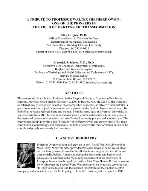
Professor Owen was born and grew up in post-World War One Liverpool in<br />
West Derby. While his father provided Professor Owen with the Welsh blood<br />
and the family name, his mother instilled in him strong intellectual skills and<br />
deep socialist beliefs. Upon completing the elementary and high-school<br />
education, he enrolled in the Metallurgy Department at the <strong>University</strong> of<br />
Liverpool from where he graduated with a First Class Honors B. Eng degree in<br />
1940. Although the Second World War interrupted his academic career he was<br />
still able <strong>to</strong> use his skills in the research labora<strong>to</strong>ries at the English Electric<br />
Company and was able <strong>to</strong> earn his M. Eng degree from the <strong>University</strong> of Liverpool in 1942.<br />
1
After the war Professor Owen returned <strong>to</strong> the Liverpool <strong>University</strong> as Lecturer in the Metallurgy<br />
Department. He received a PhD from the same university in 1950 and soon joined his academic<br />
“hero” Professor Morris Cohen, on a one year post doc<strong>to</strong>ral Commonwealth Fund fellowship, in<br />
the Department of Metallurgy at the Massachusetts Institute of Technology (MIT). While at MIT,<br />
he developed a keen interest in<strong>to</strong> bainitic, massive and martensitic transformations. He returned<br />
briefly <strong>to</strong> the Liverpool <strong>University</strong> <strong>to</strong> be called back by MIT in 1954 <strong>to</strong> assume the position of a<br />
research scientist and <strong>to</strong> lead a team investigating the brittle fracture of steels. But by 1957 he<br />
returned <strong>to</strong> the Liverpool <strong>University</strong> as Head of the Metallurgy Department and the Henry Bell<br />
Wortley Professor of Metallurgy.<br />
During his 9-year tenure as Head of the Metallurgy Department, he transformed the Department<br />
from a small academic program housed in an old workhouse <strong>to</strong> a large research and teaching<br />
institution. During this time, the department moved <strong>to</strong> the fully-refurbished George Holt<br />
Labora<strong>to</strong>ries, which had been home <strong>to</strong> the Physics Department, and Professor Owen had a new<br />
office which was once used by Nobel Prize winner James Chadwick, who discovered the<br />
neutron. During this time, the department truly flourished as talented teachers, researchers and<br />
students joined the department while Professor Owen used his industry contacts <strong>to</strong> secure<br />
funding for many large and ambitious research projects. Another of his major achievements was<br />
the introduction of new undergraduate courses <strong>to</strong> attract students from the departments of<br />
Physics and Chemistry <strong>to</strong> study metallurgy in their final year. Professor Owen also <strong>to</strong>ok an<br />
important leadership role within the <strong>University</strong> of Liverpool, as Dean of Engineering. Also while<br />
at Liverpool he joined Robert Maxwell’s Pergamon Press <strong>to</strong> stimulate publishing in the fields of<br />
metallurgy and materials science.<br />
After spending nine years at the <strong>University</strong> of Liverpool, Professor Owen returned <strong>to</strong> the United<br />
States in 1966 <strong>to</strong> assume the position of Chair of the Department of Metallurgy at Cornell<br />
<strong>University</strong> later moving on <strong>to</strong> Northwestern <strong>University</strong> where he became the Dean of the<br />
Technological Institute and Vice President for Science and Research. He returned <strong>to</strong> MIT in<br />
1973, <strong>to</strong> lead what is now known as the Department of Materials Science and Engineering as its<br />
Chair. One of his first challenges was <strong>to</strong> build consensus on renaming his department from<br />
Metallurgy and Materials Science <strong>to</strong> the Department of Materials Science and Engineering, a<br />
change that he accomplished in his second year as department head. The change was not<br />
universally popular, especially by some who were displeased that the word “metallurgy” had<br />
been dropped from the department’s title after first appearing in 1889. Soon afterwards, other<br />
<strong>to</strong>p-ranked departments followed. In his decade of tenure as Head of the Department of<br />
Materials Science and Engineering at MIT, Professor Owen led a major effort <strong>to</strong> diversify and<br />
revitalize the faculty. This resulted in significant growth in the department’s ceramics and<br />
polymers programs while its his<strong>to</strong>rical strength in metallurgy was maintained. His stewardship of<br />
the department was critical <strong>to</strong> sustaining its <strong>to</strong>p-ranked position in the succeeding decades.<br />
For his long and distinguished role in the materials science and engineering community and for<br />
"Leadership in Research on Structure/Property Relationships in Metals and in the Extension of<br />
Such Concepts <strong>to</strong> the Educational Basis of Materials Science and Engineering", he was elected<br />
<strong>to</strong> the National Academy of Engineering in 1977.<br />
Professor Owen retired from MIT in 1982 and for the last 20 years of his life he divided his time<br />
between Cambridge, Massachusetts and his beloved Welsh retreat in Porthmadog. In his later<br />
years he loved nothing more than walking along the cliff paths and chatting <strong>to</strong> the Welsh locals.<br />
In commemoration of his 80th birthday, the local authority in Porthmadog placed a plaque on a<br />
cliff <strong>to</strong>p bench “To Celebrate the Life of Professor Walter S. Owen”.<br />
2
After retirement, Professor Owen maintained a deep commitment <strong>to</strong> research, was both active in<br />
consulting and deeply committed <strong>to</strong> the education of materials scientists and engineers and <strong>to</strong><br />
furthering the evolution and development of the field of materials science and engineering,<br />
particularly in the areas of conservation, recycling, environmental concerns, public policy, and<br />
materials availability.<br />
2. OVERVIEW OF SELECTED CONTRIBUTIONS TO THE FIELD OF<br />
MARTENSITIC TRANSFORMATION<br />
Professor Owen’s research career focused on the mechanisms and consequences of martensitic<br />
transformation in ferrous systems. In an effort <strong>to</strong> illustrate the high level and longevity of<br />
contribution and his impact, we have chosen <strong>to</strong> highlight specific papers and the logic of his<br />
research themes over his entire career. Of necessity, some important contributions are omitted.<br />
Since Professor Owen worked on various aspect of martensite at three different<br />
academic/research institutions: the <strong>University</strong> of Liverpool, Cornell <strong>University</strong> and MIT, this<br />
section is structured accordingly.<br />
2.1 The <strong>University</strong> of Liverpool Years<br />
Strength of Virgin Ferrous Martensite: The extreme hardness of quenched steel is a striking<br />
phenomenon which has been the subject of speculation from earliest times. In 1939, Carpenter<br />
and Robertson [1] discussed a number of possible explanations, including age hardening and the<br />
high internal strain of freshly quenched martensite, but concluded that "the ultimate cause of the<br />
hardness remains <strong>to</strong> be discovered." In 1962, Winchell and Cohen provided the answer [2-5]:<br />
The fundamental cause is interstitial solid-solution hardening. Fe-Ni-C alloys with a<br />
transformation temperature Ms below about 250K transform <strong>to</strong> internally twinned plate<br />
martensite with an irrational habit in the vicinity of {3,10,15}γ. If the Ms temperature is near or<br />
above room temperature, lath martensite with a dislocation substructure and a habit plane near<br />
{111}γ is formed. An important distinction is that the former is tetragonal but the latter is cubic.<br />
Both are hardened substantially by carbon in solution. Winchell and Cohen [2] found that<br />
tetragonal martensite readily age hardens at temperatures near room temperature. This presented<br />
them with a problem of determining the effect of carbon content on strength of the un-aged<br />
(“virgin”) martensite in Fe-Ni-C alloys. Consequently, they had <strong>to</strong> correct their experimental<br />
results in order <strong>to</strong> remove the effect of aging that had occurred in “as-quenched” specimen<br />
during holding before testing.<br />
Roberts and Owen [6,7] extended the experimental studies of Winchell and Cohen [2-5] in two<br />
significant aspects: (a) To avoid the necessity for back extrapolation, they devised a method of<br />
rapidly quenching (>5 x 10 3 K/s) and reheating thin-foil specimens <strong>to</strong> eliminate effects due <strong>to</strong><br />
aging or tempering during specimen preparation and testing; and (b) by measuring the<br />
temperature and strain-rate dependence of the flow stress of both tetragonal twinned plate<br />
martensite, (similar <strong>to</strong> that studied by Winchell and Cohen [2-5]), and cubic lath martensite with<br />
a dislocation substructure. That this procedure was successful, even when applied <strong>to</strong> the Fe-<br />
21.3Ni-C series of alloys which formed cubic martensite at temperatures just below 373 K, is<br />
convincingly demonstrated by comparing the measured flow stresses in the two studies (Figures<br />
1 and 2). The effects of aging above 213 K are evident in the results of Winchell and Cohen but<br />
are <strong>to</strong>tally absent from those reported by Roberts and Owen.<br />
3
Figure 1. Flow stress as a function of test<br />
temperature. Open symbols: Fe-21.3Ni-<br />
C cubic martensite; Roberts and Owen<br />
[7]. Solid symbols: Fe-Ni-C tetragonal<br />
martensite; Winchell and Cohen [2].<br />
Thermally-activated Plastic Flow in Virgin Martensite: Roberts and Owen [7] made a<br />
significant contribution <strong>to</strong> utilizing stress relaxation and strain-rate change experiments over<br />
sufficient ranges of strain rate and carbon concentration <strong>to</strong> determine the thermal activation<br />
parameters controlling the kinetics of deformation of ferrous martensite. These measurements,<br />
<strong>to</strong>gether with the measurements of the temperature dependence of the flow stress at a constant<br />
strain rate, allowed them <strong>to</strong> define and parameterize one of the first dislocation-based models for<br />
thermally-activated plastic flow in martensite [7].<br />
Chemical Hardening of Virgin Martensite: Early attempts <strong>to</strong> model the plastic flow of virgin<br />
martensite [3,5] assumed a random distribution of carbon a<strong>to</strong>ms on the assigned octahedral sites<br />
of the martensite. If, however, the carbon is not arranged randomly, the possibility arises of<br />
significant strengthening resulting from an increase in the free energy of the system by a change<br />
in configurational entropy brought about by the redistribution of carbon a<strong>to</strong>ms by a dislocation<br />
sweeping a slip plane. This effect, often called “chemical hardening” and its role in plastic<br />
deformation of virgin martensite was first discussed by Roberts and Owen [7]. Their findings<br />
were subsequently confirmed by the observation that plastic deformation decreases the<br />
tetragonality of virgin martensite suggesting that a moving dislocation redis<strong>tribute</strong>s the carbon<br />
among the three types of octahedral sites or perhaps in<strong>to</strong> tetrahedral sites [8], thereby adding <strong>to</strong><br />
the incremental change in energy and, consequently, <strong>to</strong> the increase in resistance <strong>to</strong> plastic flow.<br />
2.2 The Cornell <strong>University</strong> Years<br />
The Role of Solute Drag in the Kinetics of Martensitic Interfacial Motion: The most<br />
significant research dealing with the martensitic transformation carried out by Professor Owen<br />
4<br />
Figure 2. Flow stress as a function of test<br />
temperature, showing the effects of<br />
aging above 200 K. W-C: Winchell and<br />
Cohen [2]. R-O: Roberts and Owen [7].
and his students at Cornell <strong>University</strong> dealt with the role of solute drag in the kinetics of<br />
martensitic interfacial motion [9,10]. They assumed that drag is a result of the elastic interaction<br />
of the strain fields of dissolved solute a<strong>to</strong>ms in the martensite lattice with the stress field of the<br />
moving martensitic interface. Only interstitial solutes were considered, because their associated<br />
anisotropic strain field is much larger than that of substitutional solutes. As a result of this<br />
interaction, the energy of the crystal may be reduced, under proper conditions of interfacial<br />
velocity and temperature, by one of two processes: (a) rearrangement of solute a<strong>to</strong>ms by single<br />
jumps in<strong>to</strong> energetically favorable, crystallographically equivalent neighboring sites, the Snoek<br />
model [11,12], or (b) solute diffusion over many a<strong>to</strong>mic distances, the most favorable sites being<br />
chosen at any distance from the interface, the Cottrell model [13,14]. The Snoek and Cottrell<br />
models are each simplified versions of the solute drag phenomenon. During the time required for<br />
redistribution of the solute, by either process, the interface moves a short distance so that the<br />
solute a<strong>to</strong>ms are no longer in minimum-energy positions corresponding <strong>to</strong> the new position of<br />
the interface. The result is that the solute redistribution is out of phase with the instantaneous<br />
low-energy configurations of the system and energy dissipation occurs, causing a drag on the<br />
interface.<br />
Owen et al. [9,10] adopted the solute drag model <strong>to</strong> rationalize the slow isothermal growth of<br />
{111}γ martensite in Fe-10Ni-C alloys. The elastic interaction of the strain fields of dissolved<br />
carbon a<strong>to</strong>ms in the martensite lattice with the stress field of the moving martensitic interface<br />
was determined for a specific dislocation model of the interface, consistent with the particular<br />
transformation crystallography. Only the anti-coherency interfacial dislocations were considered.<br />
It was found that the drag force produced by the Snoek interaction is quite insignificant<br />
compared with that produced by the Cottrell interaction.<br />
According <strong>to</strong> the latter model, the long range diffusion of solute a<strong>to</strong>ms <strong>to</strong> an interface moving at<br />
a constant velocity gives rise <strong>to</strong> a steady-state concentration profile, known as the Cottrell<br />
atmosphere. This profile is obtained by solving the governing differential equation for the<br />
velocity of the interface, vR, relative <strong>to</strong> the solute a<strong>to</strong>ms in the atmosphere:<br />
D ∂w<br />
D ∂C0<br />
vR = − − − v<br />
(1)<br />
kT ∂x<br />
C0<br />
∂x<br />
where D is the diffusion coefficient, w is the solute/interface elastic interaction energy, Co the<br />
solute concentration, k the Boltzmann constant, T the temperature, x a spatial coordinate, and v is<br />
the interface velocity. Equation 1 is subjected <strong>to</strong> the appropriate boundary conditions and the<br />
continuity condition ( ∂ / ∂x<br />
)( C0<br />
vR<br />
) = 0.<br />
The <strong>to</strong>tal solute drag force is then obtained by integrating<br />
the solute/interface interaction forces over the volume of the Cottrell atmosphere. An exact,<br />
analytical, closed-form solution for the drag force is obtainable only in the limits of low and high<br />
interfacial velocities. However, an approximate solution for the drag force fitting all velocity<br />
regimes can be developed [15].<br />
An example of the calculated drag force vs. interfacial velocity results at 723K for the Cottrell<br />
interaction of carbon a<strong>to</strong>ms with the martensite interface in a series of Fe-10Ni-C alloys with<br />
different carbon levels is shown in Figure 3. It is interesting <strong>to</strong> note that, for a typical magnitude<br />
of the thermodynamic driving force at the Ms of about 1090 J/mol, none of the alloys<br />
investigated experience an instability in the interfacial motion. Consequently, a stableequilibrium<br />
condition corresponding <strong>to</strong> the balance between the driving force and the drag forces<br />
is attained. This finding then predicts in a stable slow-rate martensite growth, Figure 4, which<br />
5
was confirmed experimentally [9,10]. Furthermore, except for the alloys with the least amount of<br />
carbon, the drag force is predicted <strong>to</strong> be a linear function of the interfacial velocity, Figure 3.<br />
Figure 3. Calculated force-velocity curves for the<br />
Cottrell interaction of carbon a<strong>to</strong>ms with the massive<br />
martensite boundary at 723 K for various carbon levels<br />
[10].<br />
A comparison of the calculated interfacial velocities and measured growth rates (in the width<br />
direction) for Fe-10Ni-C alloys at 723K is given in Figure 4. The calculated curves are for<br />
different values of Rγ, and correspond <strong>to</strong> different approximations regarding the additional<br />
frictional forces opposing the interfacial motion. These were assumed <strong>to</strong> be independent of the<br />
velocity of the interface and, hence, <strong>to</strong> simply lower the net driving force. The model predicts a<br />
steep drop in growth rate with the initial small addition of carbon, in excellent agreement with<br />
the experimental observations. However, the growth rates predicted by the solute drag model<br />
[9,10] were one or two orders of magnitude larger than their measured counterparts. The extent<br />
of this discrepancy was found <strong>to</strong> be affected by several fac<strong>to</strong>rs such as: (a) the chosen value of<br />
the additional frictional forces; (b) the choice of the interfacial-dislocation core cu<strong>to</strong>ff radius;<br />
and (c) the assumptions made regarding the diffusion coefficient within the Cottrell atmosphere.<br />
While these fac<strong>to</strong>rs can be adjusted <strong>to</strong> obtain a good quantitative agreement between the model<br />
and the experiment, the assumptions required could not be deemed fully justified. Schoen and<br />
Owen [10] correctly pointed out that the main cause for the over-prediction of the martensite<br />
growth rates is the assumption of linear elastic interactions used in their model.<br />
2.3 The MIT Years<br />
Definition of Thermo-elastic Martensitic Transformation: One of the significant contributions<br />
of Professor Owen and his students at MIT was helping properly define the notion of thermoelasticity.<br />
There are two sources of dislocation generation that are transformation induced. If the<br />
transformation shape change cannot be <strong>to</strong>tally accommodated elastically and appreciable plastic<br />
deformation by slip takes place, an increase in the matrix dislocation density results, with<br />
possible loss of interfacial mobility due <strong>to</strong> dislocation jamming. The concurrent relaxation of the<br />
elastic field around the martensite particle also decreases the thermodynamic driving force<br />
6<br />
Figure 4. Comparison of experimental<br />
and theoretically calculated width growth<br />
rates for Fe-l0Ni-C alloys at 723 K [10].
available during the reverse interface motion. Transformations accompanied by significant<br />
plastic accommodation are not thermo-elastic.<br />
Dislocations may also be generated by the moving interface. In many alloys in which the<br />
transformation is thermo-elastic, the lattice invariant strain is produced by the formation of a<br />
stack of thin, parallel twins with alternating twinning directions. At the interface of such a plate,<br />
there are local accommodation strains which may be elastic when the twins are thin, but plastic if<br />
they are not [16]. When a plate of the latter type shrinks, the moving interface leaves behind<br />
trails of sessile dislocation loops. On reversing the direction of the moving interface, the<br />
interface remains stable and glissile as it moves through the dislocation debris [17]. The density<br />
of dislocations in the matrix increases with each reversal of growth direction until it reaches<br />
some limiting density [18]. Thus, in these alloys, there is local irreversible deformation produced<br />
not by the shape change but by the moving interface.<br />
Taking all these facts in<strong>to</strong> account, Ling and Owen [19,20] classified a transformation as thermoelastic<br />
if the motion of the interface is reversible, even though there may be a significant thermal<br />
hysteresis due <strong>to</strong> a high density of interface generated dislocations in the matrix. They further<br />
identified elastic accommodation of the transformation shape change as the essential condition<br />
for thermo-elastic growth. With this definition, thermo-elastic growth is favored by a small<br />
chemical driving force at the Ms, a small transformation shape strain, and a matrix with a high<br />
flow stress [21].<br />
Most thermo-elastic alloys, such as the inter-metallic β-phase alloys, have these properties. An<br />
exception is a group of ferromagnetic iron alloys, such as ordered Fe3Pt, which have a shape<br />
deformation similar in magnitude <strong>to</strong> that in other ferrous alloys that do not transform thermoelastically.<br />
The chemical driving force in ordered Fe3Pt is also substantially higher than in βphase<br />
alloys. Ling and Owen [19,20] recognized that this, in part, reflects the larger elastic<br />
accommodation strain energy, but also that the absence of soft elastic modes (comparable with<br />
those found in the β-phase alloys), is an additional important reason why the driving force at Ms<br />
is relatively large in Fe3Pt.<br />
Computer Modeling of the Growth of Thermo-elastic Martensite: Ling and Owen [19,20]<br />
developed one of the first computer models of thermo-elastic growth which enabled<br />
determination of the largest plate which can behave thermo-elastically. They were also able <strong>to</strong><br />
calculate the associated strain energy and, thus, the maximum driving force at the Ms. By<br />
calculating the plastic-zone size of a martensite particle in equilibrium at the Ms temperature, the<br />
model was next used <strong>to</strong> assess relative propensity of a given alloy system <strong>to</strong> exhibit thermoelastic<br />
growth.<br />
The model of Ling and Owen [19,20] was a three-dimensional continuum model which<br />
considered contributions of both the shear and the dilatational transformation strains. The first<br />
plate of martensite <strong>to</strong> form at Ms was assumed <strong>to</strong> nucleate within a grain in a polycrystalline<br />
aggregate and <strong>to</strong> grow rapidly in the radial direction, until s<strong>to</strong>pped by a grain boundary or other<br />
barrier. The plate is then assumed <strong>to</strong> thicken in a direction, normal <strong>to</strong> the plane of the thin plate.<br />
The resulting lenticular plate was represented by an oblate spheroid. The matrix and the<br />
martensite were assumed <strong>to</strong> be elastically isotropic, but with different elastic moduli.<br />
The martensite plate was assumed <strong>to</strong> be a coherent particle embedded in an infinite matrix of the<br />
parent phase. The martensitic-transformation induced stresses in the plate and in the matrix were<br />
calculated using Eshelby's model [22]. It was further assumed that plastic flow occurs in a<br />
7
volume enclosed by a surface at which the von Mises criterion for yielding is satisfied. The<br />
effect of yielding-induced stress relaxation on the size of the transformation zone was not<br />
considered since in order <strong>to</strong> understand thermo-elastic growth, it is important <strong>to</strong> know only<br />
whether or not significant plastic flow occurs.<br />
The elastic properties of the matrix were found <strong>to</strong> play a significant role in the process of<br />
accommodation. In this regard, a favorable fac<strong>to</strong>r for thermo-elastic growth is pre-martensitic<br />
elastic softening of the lattice (Figure 5), which may be caused by different phenomena in<br />
different alloy systems. Alloys that transform thermo-elastically all have an anomalous positive<br />
temperature dependence of the elastic constant C’ = (C11 - C12)/2 over a temperature range that<br />
includes the Ms temperature. Elastic softening affects the transformation in two ways: it reduces<br />
the chemical driving force at the nucleation stage, and it facilitates the elastic accommodation of<br />
the lattice shape change. Thus, a plate that grows thermo-elastically at Ms will continue this form<br />
of growth as the temperature is lowered.<br />
Figure 5. Temperature dependence of<br />
the average shear modulus, G, as a<br />
function of the degree of order S in<br />
Fe3Pt [20].<br />
Most thermo-elastic alloys possess long-range order which increases their yield strength and,<br />
thus, inhibits plastic yielding. Alloys that are ferromagnetic at the Ms temperature, such as Fe3Pt,<br />
are further strengthened by a magne<strong>to</strong>striction effect known as "Invar strengthening," which is a<br />
function of the degree of order, S [23]. Ling and Owen [19,20] made a major contribution <strong>to</strong> our<br />
better understanding of the role of long-range order in accommodation of the macroscopic shape<br />
change accompanying martensitic transformation. An example of the results obtained by Ling<br />
and Owen [19,20] pertaining <strong>to</strong> the size of the yield envelopes associated with an isolated<br />
martensite plate as a function of the degree of long-range order S is shown in Figure 6. The<br />
change in the yield-envelope size demonstrates the importance of long-range order. A thin plate<br />
(aspect ratio = 0.02) in a disordered matrix (S =0) is completely enclosed within a yield<br />
envelope. However, in all cases where S > 0.2, matrix yielding is confined <strong>to</strong> a small zone at the<br />
radial edge of the plate. The change is particularly striking between S =0 and S =0.2. Over this<br />
8<br />
Figure 6. Matrix yield stress con<strong>to</strong>urs<br />
of an oblate spheroid lying in the x-y<br />
plane with the transformation shear in<br />
the x direction [20].
narrow range, the elastic softening is dramatic (Figure 6), and the Ms temperature decreases more<br />
than 80 K. The growth is predicted <strong>to</strong> be irreversible in disordered specimens but <strong>to</strong> be thermoelastic<br />
in those with S >= 0.2. Subsequent experimental investigation of the martensite growth in<br />
Fe3Pt confirm these predictions [19,20].<br />
The model of Ling and Owen [19,20] revealed the following important basic fact: Even in the<br />
most favorable circumstances when a Fe3Pt alloy is nearly fully ordered, growth of an isolated<br />
plate can proceed thermo-elastically only while the plate is thin. In sharp contrast, their<br />
experimental investigation showed that the transformation in ordered Fe3Pt goes <strong>to</strong> completion<br />
while remaining thermo-elastic. Clearly, for this <strong>to</strong> happen, the transformation strains must be<br />
relieved by a reversible elastic deformation process. In the case of ordered Fe3Pt, they observed<br />
that additional thin plates of martensite are repeatedly nucleated in the accommodation strain<br />
fields of previously nucleated plates.<br />
Following the aforementioned observation, Ling and Owen [19,20] expanded their model <strong>to</strong><br />
include the case of multiple nucleated plates. In general, as an isolated plate of thermo-elastic<br />
martensite thickens, the large shear stresses near the edge (tip) and over the broad surface of the<br />
plate assist the nucleation of adjacent plates. In the plastic zone near the edge, nucleation may be<br />
strain induced, and nonparallel crystallographic variants of the plate may form edge <strong>to</strong> edge.<br />
Alternatively, stress-assisted nucleation adjacent <strong>to</strong> the broad interface may produce a variant<br />
approximately parallel <strong>to</strong> the original plate. The change in the yield-envelope size and shape<br />
associated with putting <strong>to</strong>gether two parallel plates of opposite shear <strong>to</strong>uching along the z-axis<br />
obtained by Ling and Owen [19,20] is displayed in Figure 7. It is seen that while the yield<br />
envelope of an isolated oblate spheroid (c/r =0.8) in a matrix with S =0.6 completely encloses<br />
the plate (Figure 6), for two parallel, <strong>to</strong>uching plates of opposite shear, each with c/r = 0.08, only<br />
a small yield envelope confined <strong>to</strong> the edges of the plates is produced (Figure 7). Ling and Owen<br />
[19,20] further demonstrated that as more plates are added <strong>to</strong> the stack, the yield envelope<br />
continues <strong>to</strong> shrink.<br />
Figure 7. Matrix yield stress con<strong>to</strong>urs<br />
of two parallel ellipsoidal plates with<br />
opposite shear strain. Aspect ratio:<br />
0.08 [20].<br />
In general, as an isolated plate of thermo-elastic martensite thickens, the large shear stresses near<br />
the edge (tip) and over the broad surface of the plate assist the nucleation of adjacent plates. In<br />
the plastic zone near the edge, nucleation may be strain induced, and nonparallel crystallographic<br />
9
variants of the plate may form edge <strong>to</strong> edge. Alternatively, stress-assisted nucleation adjacent <strong>to</strong><br />
the broad interface may produce a variant approximately parallel <strong>to</strong> the original plate. The<br />
change in the yield envelope on putting <strong>to</strong>gether two parallel plates of opposite shear <strong>to</strong>uching<br />
along the z-axis is displayed in Figure 7. It is seen that while the yield envelope of an isolated<br />
oblate spheroid (c/r =0.8) in a matrix with S =0.6 completely encloses the plate (Figure 6), for<br />
two parallel, <strong>to</strong>uching plates of opposite shear, each with c/r = 0.08, only a small yield envelope<br />
confined <strong>to</strong> the edges of the plates is produced (Figure 7). Additional calculations show that as<br />
more plates are added <strong>to</strong> the stack, the yield envelope continues <strong>to</strong> shrink.<br />
Dynamics of Thermo-elastic Martensitic Interfacial Motion: One of the last contributions of<br />
Professor Owen <strong>to</strong> the field of martensitic transformation pertains <strong>to</strong> the experimental<br />
characterization, modeling and computer simulations of the basic dynamics of martensitic<br />
interface motion. It is well-established that the analysis of martensite growth must include a<br />
consideration of the following two fundamental phenomena: (a) dynamics of interfacial motion<br />
and: (b) accommodation of the transformation strain under consideration of variant selection.<br />
The structural changes occurring during the transformation require special interfaces between the<br />
parent phase and martensite, whose dynamics holds the key <strong>to</strong> many kinetic aspects of<br />
transformation. On the other hand, accommodation of the transformation strain may control<br />
morphological development of a martensite plate. While in the case of non-thermo-elastic<br />
martensite, there is a dynamic interaction between the interfacial dynamics and plastic<br />
accommodation of the transformation strain which may govern the path of martensite growth,<br />
Owen and co-workers [24-27] recognized that, in the case of thermo-elastic martensite, the role<br />
of plastic accommodation of the transformation strain is minimal and that this transformation,<br />
hence, offers a unique opportunity for studying the basic dynamics of martensitic interfacial<br />
motion.<br />
Owen and co-workers [24-27] further recognized that the dislocation models for martensitic<br />
interfacial structure proposed in the literature suggest that the dynamics of interfacial motion can<br />
be analyzed using the formalisms developed <strong>to</strong> describe dislocation dynamics. A general<br />
dislocation description of the martensitic interface has been developed by Olson and Cohen<br />
[28,29] and Olson [30] who introduced two types of interfacial dislocations: a) the “coherency<br />
dislocations” which, as they move with the interface, accomplish the lattice deformation while<br />
maintaining the continuity of crystal lines and directions across the interface and; (b) the “anticoherency<br />
dislocations” which, being true lattice discontinuities, disrupt the lattice continuity<br />
and, as they move, produce the lattice invariant deformation in martensite. A simultaneous<br />
operation of the two deformation modes, the lattice deformation and the lattice invariant<br />
deformation, leave the interface plane macroscopically invariant, i.e., undis<strong>to</strong>rted and un-rotated.<br />
Within their work, Owen and co-workers [24-27] analyzed the basic dynamic behavior of<br />
martensitic interfaces using the framework of lattice dislocation dynamics. Two limiting cases<br />
of the martensitic interface structure were considered: (a) the case when the interface can be<br />
appropriately described in terms of an array of non-interacting (well-spaced) interfacial<br />
dislocations; and (b) the case when the interfacial dislocations are so closely spaced that the<br />
interface can be approximated by a continuous distribution of dislocations. In the first case, they<br />
demonstrated that the interfacial dynamics can be analyzed by including a<br />
“chemical/transformation” driving force in the equation of motion for a single lattice dislocation.<br />
In the second case, on the other hand, while the lattice dislocation dynamics is still relevant,<br />
several parameters in the equation of motion had <strong>to</strong> be redefined <strong>to</strong> reflect the fact that the<br />
interface now acts as a planar defect. For both the aforementioned dislocation models of<br />
10
martensitic-interfacial structure, the two basic modes/regimes of interfacial motion were<br />
considered: (a) the continuous mode in which the motion is sustained and controlled by various<br />
energy-dissipative processes (e.g., phonon and electron drag) and; (b) the discontinuous or jerky<br />
mode in which the motion is controlled by thermal activation of the interface/obstacle<br />
interactions.<br />
The continuum regime of martensitic interfacial motion was analyzed using the framework<br />
initially developed in Professor Owen’s research group at Cornell <strong>University</strong> [9,10]. On the<br />
other hand, the thermally activated regime of martensitic interfacial motion carried out by Owen<br />
and co-workers [24-27] at MIT was a new direction in the research and is briefly overviewed<br />
below.<br />
The basic concept of thermally activated dislocation motion can be unders<strong>to</strong>od by analyzing the<br />
schematic dislocation/obstacle interaction force-distance profile depicted in Figure 8.<br />
Representing the position of a dislocation segment by the area swept during its motion, a, the<br />
variation of the internal friction stress with the position defines a τ vs. a profile of the form<br />
given in Figure 8(a). For an applied stress τ A , the dislocation is in stable equilibrium at point a1.<br />
To reach the point a2 of unstable equilibrium, the dislocation must overcome its activation energy<br />
Q1 defined by the shaded area under the curve in Figure 8(a). During such a thermally activated<br />
event, the dislocation line sweeps an “activation area” a*, whose magnitude is a function of τ A ,<br />
as shown in Figure 8(b). The activation energy can be obtained by the following integration:<br />
a1<br />
∫<br />
ˆ τ<br />
A<br />
A<br />
*<br />
Q(<br />
τ ) = b ( τ −τ<br />
) da = a dτ<br />
(2)<br />
a1<br />
Figure 8. Schematic<br />
dislocation/obstacle interaction<br />
profiles. (a) Force-distance profile.<br />
(b) “Sheared profile” representing<br />
stress vs. activation area or driving<br />
force vs. activation-volume relation<br />
[25].<br />
τ<br />
∫<br />
A<br />
11<br />
Figure 9. Schematic<br />
representation of the<br />
interaction between an<br />
interface and regularly<br />
dis<strong>tribute</strong>d discrete<br />
particles with average<br />
planar spacing [25].<br />
Figure 10. Normalized activation energy vs. driving force<br />
plot showing a comparison between different model<br />
predictions and the experimental mobility data in a Cu-<br />
14.3Al-4.0Ni single crystal [26].
The overall velocity of the dislocation in the thermally activated region, υ, is governed by the<br />
rate at which the dislocation overcomes the barrier and is defined as:<br />
⎛ Q ⎞<br />
υ = υ0<br />
exp⎜−<br />
⎟<br />
(3)<br />
⎝ kT ⎠<br />
where the pre-exponential fac<strong>to</strong>r υ0 is proportional <strong>to</strong> the corresponding attempt frequency. The<br />
two activation parameters, the activation area and the activation energy and their dependence on<br />
the applied stress can be determined from experimental dislocation mobility data using the<br />
following relations:<br />
∂ lnυ<br />
Q = (4)<br />
∂<br />
( −1<br />
kT ) A<br />
τ<br />
* kT ∂ lnυ<br />
1 ∂Q<br />
a = = −<br />
(5)<br />
A<br />
A<br />
b ∂τ<br />
T b ∂τ<br />
T<br />
When an interface consists of an array of well-spaced dislocations, the τ vs. a* profile for the<br />
interfacial dislocations can be used <strong>to</strong> describe the interface/obstacle interaction. Conversely,<br />
when the interface is more appropriately described in terms of a continuous distribution of<br />
dislocations, the thermally activated event is three-dimensional in nature. For this case Owen and<br />
co-workers [24-27] introduced an “activation volume” V* as:<br />
* ∂Q<br />
V =<br />
(6)<br />
∂Δg<br />
T<br />
and demonstrated that the thermal activation analysis of the interfacial motion can be formulated<br />
in terms of the corresponding (driving force) Δg vs. V* profile. For an interface consisting of<br />
well separated dislocations, V* can be defined in terms of a* through the relation:<br />
* *<br />
V = da<br />
(7)<br />
When an obstacle profile such as the one shown in of Figure 8 pertains <strong>to</strong> long-range<br />
interface/obstacle interactions, V* becomes very large and consequently, the role of thermal<br />
activation becomes less important. If the interface can be described in terms of an array of wellspaced<br />
dislocations, the interface/obstacle interactions result in a velocity-invariant friction<br />
stress τμ which oppose the interface motion by lowering the net applied stress. In other words,<br />
the “thermal” component of τ Α that can assist thermal activation of the dislocation over shortrange<br />
obstacles now becomes τ Α - τμ . When several short-range obstacles simultaneously interact<br />
with an interface, the overall obstacle profile can be defined by the root sum of the squares of the<br />
individual profiles. Again, when the interface is more appropriated represented by a continuous<br />
distribution of dislocations, the “athermal” and the “thermal” components of the interfacial force<br />
should be defined in terms of Δg rather than τ.<br />
As a dislocation moves through a perfect crystal, its core energy varies in a periodic manner due<br />
<strong>to</strong> the translational symmetry of the lattice. The resulting periodic lattice friction force, the<br />
Peierls barrier, can become the rate controlling mechanism of dislocation motion at lower<br />
temperatures. When an interface can be described in terms of well separated dislocations, the<br />
interfacial dislocations may be considered <strong>to</strong> interact individually with the periodic lattice<br />
potential in much the same manner as the lattice dislocations. For the case when interfacial<br />
12
dislocations are closely spaced and the interface is more properly treated as a 2-dimensional<br />
entity, Owen and co-workers [24-27] developed a Peierls-type interfacial friction model.<br />
While the effect of the Peierls barrier may be important in the growth of microscopic martensite<br />
particles under weak driving forces, Owen and co-workers [24-27] recognized that the motion of<br />
an interface of macroscopic dimensions, just like the motion of lattice dislocations, is more likely<br />
controlled by its interaction with crystal defects. For example, it is well established that cutting<br />
of repulsive forest dislocations by other dislocations, which involves generation of elementary<br />
jogs, gives rise <strong>to</strong> a significant strain hardening of metals at moderate temperatures. Likewise,<br />
the interaction of dislocations with attractive forest dislocations gives rise <strong>to</strong> long-range<br />
“athermal” friction stresses which oppose dislocation motion. Similar line-line interactions are<br />
expected <strong>to</strong> control the interfacial dynamics when the interface structure is dominated by wellspaced<br />
anti-coherency dislocations. The interactions of closely spaced coherency dislocations<br />
with forest dislocations, can also be important but this interaction, was treated as a line-surface<br />
problem.<br />
Since the interface can interact with remote forest dislocations, the resulting interfacial friction<br />
stress was recognized <strong>to</strong> be predominantly of the long range character and, thus, athermal.<br />
Similar conclusions were drawn for surface-surface interactions involving the martensitic<br />
interface and other surface defects, such as anti-phase boundaries. It was also noted that besides<br />
giving rise <strong>to</strong> additional (athermal) friction stresses, the line-surface and surface-surface<br />
interactions may be of a potential importance in assisting the generation of coherency<br />
dislocations by a pole mechanism during thickening of small martensitic particles.<br />
Discrete defects which take part in point-surface interactions were identified as the defects that<br />
most likely control thermally activated interfacial motion. These interactions can be both a longrange<br />
(athermal) character as well as of the short-range (thermal) character. The interaction of an<br />
interface with regularly dis<strong>tribute</strong>d localized discrete particles, with average planar spacing λ¸<br />
(Figure 9), has been analyzed by Owen and co-workers [24-27]. For a simplified dislocation<br />
model of interfacial structure, and using the analytical expressions for the corresponding<br />
interfacial stress field, Owen and co-workers [24-27] derived the driving force vs. activation<br />
volume obstacle profiles for long- and short-range strain and modulus interface/ obstacle<br />
interactions. Furthermore by applying an integration procedure analogous <strong>to</strong> the one indicated by<br />
Eq. (2), the corresponding Q vs. Δg relations were derived. The results of this procedure are<br />
shown in Figure 10. Labels “slip” and “twin” were used in Figure 10 <strong>to</strong> indicate the nature of the<br />
lattice-invariant deformation. It is cus<strong>to</strong>mary <strong>to</strong> represent the Q vs. Δg relations as the ones<br />
shown in Figure 10, by the following expression:<br />
q<br />
p<br />
⎡ ⎛ Δg<br />
− Δg<br />
⎤<br />
μ ⎞<br />
Q = Q ⎢ ⎜ ⎟ ⎥<br />
0 1−<br />
(8)<br />
⎢ ⎜ g g ⎟ ⎥<br />
⎣ ⎝ Δ ˆ − Δ μ ⎠ ⎦<br />
where Q0 is the maximum activation energy, Δgμ is the athermal part of Δg, and the exponents p<br />
and q describe, respectively, the long-range (small Δg ) and the short-range (large Δg)<br />
interfacial/obstacle interaction behavior. The characteristic values of p and q for the various<br />
interface/particle interactions are summarized in Table 1. The results shown in Figure 10 and<br />
Table 1 suggest that the interaction of a “slip” interface with the same array of discrete obstacles,<br />
is significantly different than that of a “twin” interface. Owen and co-workers [24-27] also found<br />
that the magnitudes of Q0 and Δg ^ are both substantially larger for a “slip” interface, than a<br />
13
“twin” interface. The last finding suggests that a “twin” interface is intrinsically more mobile<br />
than the “slip” interface.<br />
Table 1. Values of p and q exponents in Eq.<br />
(3) for various types of interface/particle<br />
interactions.<br />
Figure 12. Comparison of the model predictions<br />
for the strain-interaction obstacle profile (solid<br />
lines) and the experimentally measured obstacle<br />
profile in a Cu-14.3Al-4.0Ni single crystal [27].<br />
To validate their model for thermally-activated martensitic interfacial motion, Owen and coworkers<br />
[24-27] carried out a comprehensive experimental investigation of stress-assisted singleinterface<br />
martensitic transformation in single crystals of thermo-elastic Cu-Al-Ni alloys. Figure<br />
11 shows the measured temperature dependence of the interfacial friction stress and the<br />
corresponding driving force for the interfacial velocities in the range between 10 -6 and 10 -3 m/s<br />
in a Cu-14.3Al-4.0Ni single crystal. As indicated by the dashed line in Figure 11, there is a welldefined<br />
athermal interfacial friction stress, τμ. The corresponding Δg vs. V* and Q vs. Δg<br />
14<br />
Figure 11. Temperature and velocity<br />
dependence of the friction stress (driving force)<br />
in a Cu-14.3Al-4.0Ni single crystal [26].<br />
Figure 13. Comparison of the model prediction<br />
(solid curves) for the strain-interaction<br />
activation energy vs. driving force relation and<br />
the experimentally measured relations between<br />
activation energy and driving force in a Cu-<br />
14.3Al-4.0Ni single crystal [27].
obstacle profile associated with the thermal part of the applied stress are shown in Figures 12 and<br />
13, respectively. The Q vs. Δg relation was found <strong>to</strong> be consistent with Eq. (8) with Q0 =0.305<br />
eV, - Δg ^ = 0.9 MJ/m 3 , Δgμ = 2.21 MJ/m 3 , p= 0.39, and q =1.35. These values for p and q were<br />
found <strong>to</strong> be in good agreement with the interfacial motion model of Owen and co-workers [24-<br />
27] when an interfacial dislocation model specific <strong>to</strong> the twinned β1-γ1 ’ martensitic interface was<br />
used. By analyzing both the interfacial mobility data and the transmission electron microscopic<br />
results of the parent β1-phase, Owen and co-workers [24-27] determined that the thermalactivated<br />
motion of the β1-γ1 ’ interface is controlled by the “tweed” structure, consisting of highmodulation<br />
displacement fields. The athermal frictional stress, on the other hand, was at<strong>tribute</strong>d<br />
<strong>to</strong> be a long-range modulus interaction of the interface with discrete 2H precipitated in the β1phase.<br />
3. A PERSONAL TRIBUTE<br />
The following comments were made by one of us (FJS) at a memorial event at MIT in November<br />
19, 2007, attended by his family, friends and colleagues over many years. These comments<br />
especially exemplify the impact that Professor Owen had on the developing careers of young<br />
people.<br />
“I was one of the first doc<strong>to</strong>ral students doing graduate study under Professor Walter Owen’s<br />
tutelage at Cornell <strong>University</strong>, beginning in September 1966, shortly after he arrived from<br />
Liverpool. It was clear that Professor Owen derived immense satisfaction from his teaching,<br />
men<strong>to</strong>ring and association with young people, as well as his research in physical metallurgy. It<br />
was also apparent that he had a high commitment <strong>to</strong> excellence in a model of learning that shared<br />
responsibility between students and teachers, and he was eminently respectful and caring of the<br />
professional and personal needs of both students and his faculty colleagues. I remember best his<br />
friendly, encouraging, and optimistic manner that gently pushed me and my colleagues <strong>to</strong> do our<br />
best work, as much of it as possible, and as rigorously as possible. He was extremely generous<br />
with his time and energy, and a key contribution he made <strong>to</strong> my career and I’m sure the careers<br />
of my fellow students, accrued from the relaxed but focused technical sessions he held for his<br />
entire group of graduate students and postdoc<strong>to</strong>ral fellows at his home in Ithaca, one evening per<br />
month. At these work-in-progress sessions we learned how <strong>to</strong> thoughtfully prepare a technical<br />
talk, communicate ideas <strong>to</strong> a scholarly group of peers, and vigorously defend our thinking on our<br />
feet, skills I continue <strong>to</strong> benefit from <strong>to</strong>day. As we had learned the art of preparation for a<br />
scientific presentation through these sessions, I was appalled one day when I saw him depart for<br />
a major out-of-<strong>to</strong>wn talk and grab his box of slides (in those days a several pound mass of glass),<br />
not yet organized for the talk, and proceeded <strong>to</strong> the airport. Little did I realize that that was often<br />
the “modus operandi” of a seasoned professional (and a style that I and many colleagues<br />
regrettably adapted later as our careers matured).<br />
Walter was truly a good men<strong>to</strong>r, and he taught me how <strong>to</strong> think critically about science in<br />
general. I shall always be grateful that he supported and followed (and I believe even relished)<br />
the evolution of my career from martensite metallurgy (the area he loved) as a PhD student, in<strong>to</strong><br />
biomaterials, biomedical engineering and medicine, areas he knew much less about. Only in<br />
preparation for these remarks did I uncover an article in the Cornell Engineering Quarterly in<br />
1970 in which he predicted that the field of biomaterials would be a “growth area” <strong>to</strong> which<br />
materials science would con<strong>tribute</strong> immensely (and how correct he was).<br />
15
Walter was the Thomas R. Briggs Professor and Direc<strong>to</strong>r of the Department of Materials Science<br />
and Engineering at Cornell from 1966 <strong>to</strong> 1970 when he under<strong>to</strong>ok his new appointment as Dean<br />
of the Technological Institute at Northwestern <strong>University</strong>. When he came <strong>to</strong> Cornell in 1966 he<br />
<strong>to</strong>ok over a young department, which became a separate Materials Science and Engineering<br />
Department only the previous year. Within a year there were approximately forty students doing<br />
graduate materials study at Cornell. Through his leadership, Professor Owen established MS&E<br />
at Cornell as one of the few leading departments of its kind, composed of a distinguished group<br />
of materials specialists and strong academic programs. He developed excellent and synergistic<br />
collaborations with groups doing physics, chemistry and mechanics, thereby creating a highly<br />
interdisciplinary and intellectually stimulating environment. Through his leadership of the<br />
Department at Cornell, Walter con<strong>tribute</strong>d greatly <strong>to</strong> the development of materials science as a<br />
systematized science and academic discipline. Owing <strong>to</strong> his contributions then and subsequently,<br />
materials science has flourished, increasing in sophistication and contributing <strong>to</strong> many important<br />
scientific and engineering advances.<br />
It was a privilege and an honor <strong>to</strong> be his colleague and friend for over 40 years.”<br />
4. FINAL REMARKS<br />
With his devotion <strong>to</strong> family, friends, research, teaching and professional service, Professor Owen<br />
has left behind a vast number of grieving people whose lives were <strong>to</strong>uched and improved by his<br />
presence. He was a role model for many of us over the years, and he will live on in the<br />
memories of those who knew him. We will always remember Professor Owen.<br />
5. REFERENCES<br />
1. H. Carpenter and J. M. Robertson, Metals, Oxford <strong>University</strong> Press, 1939, 913, 1083.<br />
2. P. G. Winchell and M. Cohen, Trans. ASM, 55, 1962, 347.<br />
3. P. G. Winchell and M. Cohen, in Electron Microscopy and the Strength of Metals, G.<br />
Thomas and J. Washburn, Ed., Interscience, 1963, 995.<br />
4. M. Cohen, Trans. AIME, 224, 1962, 638.<br />
5. M. Cohen, J. Iron Steel Inst., 201, 1963, 833.<br />
6. M. J. Roberts and W. S. Owen, "Physical Properties of Martensite and Bainite," Iron and<br />
Steel Institute Special Report No. 93, 1965, 171.<br />
7. M. J. Roberts and W. S. Owen, J. Iron Steel Inst., 206, 1968, 375.<br />
8. F. E. Fujita, T. Moriya, and H. Ino, in Proc. Int. Conf. Sci. Technol. Iron Steel, Iron and Steel<br />
Institute of Japan, 1971, 1273.<br />
9. W. S. Owen, F. J. Schoen, and G. R Srinivasan, in Phase Transformations, American Society<br />
for Metals, 1970, 157.<br />
10. F. J. Schoen and W. S. Owen, Metall. Trans., 2, 1971, 2431.<br />
11. J. Snoek, Physics, 8, 1941, 711.<br />
12. G. Schoeck and A. Seeger, Acta Metall., 7, 1959, 469.<br />
13. A. H. Cottrell and B. A Bilby, Proc. Phys. Soc., 62, 1949, 49<br />
16
14. A. H. Cottrell and M. A Jaswon, Proc. Roy. Soc. Land., A199, 1949, 104<br />
15. J. W. Cahn, Acta Metall., 10, 1962, 789.<br />
16. S. Kajiwara and W. S. Owen, Scr. Metall., 11, 1977, 137.<br />
17. S. Kajiwara and W.S. Owen, Metall. Trans., 4, 1973, 1988.<br />
18. G. D. Sandrock, A. J. Perkins, and R. E Hehemann, Metall. Trans., 2, 1971, 2769.<br />
19. H. C. Ling and W. S. Owen, Scr. Metall., 15, 1981, 1115.<br />
20. H. C. Ling and W. S. Owen, Acta Metall., 29, 1981, 1721.<br />
21. J. W. Christian, The Theory of Transformations in Metals and Alloys, Pergamon Press,<br />
Oxford, 1965, 816.<br />
22. J. D. Eshelby, Prog. Sol. Mech., 7, 1961.<br />
23. M. J. Schmutz, Doc<strong>to</strong>ral thesis, Massachusetts Institute of Technology, 1978.<br />
24. M. Grujicic, G. B. Olson, and W. S. Owen, J. Phys. (Suppl. 12) 43, 1982, C4-173.<br />
25. M. Grujicic, G. B. Olson, and W. S. Owen, Metall. Trans. 16A, 1985, 1713.<br />
26. M. Grujicic, G. B. Olson, and W. S. Owen, Metall. Trans. 16A, 1985, 1723.<br />
27. M. Grujicic, G. B. Olson, and W. S. Owen, Metall. Trans. 16A, 1985, 1735.<br />
28. G. B. Olson and M. Cohen, Acta Metall. 27, 1979, 1907.<br />
29. G. B. Olson and M. Cohen, in Proc. Int. Conf. Solid-Solid Phase Transformations, edited by<br />
H. I. Aaronson , TMS-AIME, 1982, 1209.<br />
30. G. B. Olson, Acta Metall. 29, 1981, 1475.<br />
17


