SERVICE MANUAL Jeep Grand Cherokee WJ 44-4 - Spicer
SERVICE MANUAL Jeep Grand Cherokee WJ 44-4 - Spicer
SERVICE MANUAL Jeep Grand Cherokee WJ 44-4 - Spicer

Create successful ePaper yourself
Turn your PDF publications into a flip-book with our unique Google optimized e-Paper software.
X5001-CVSP<br />
1<br />
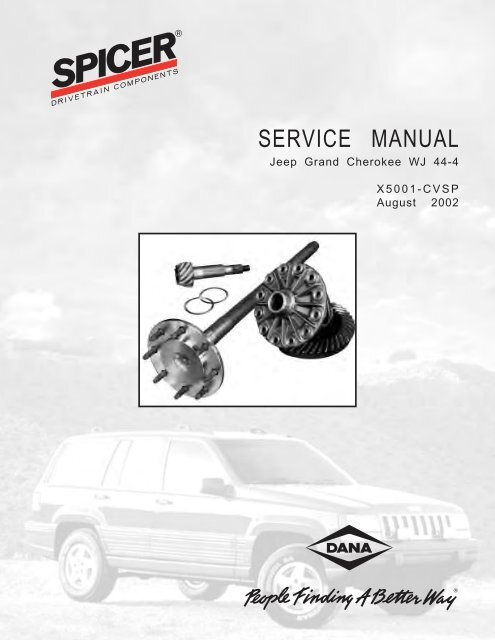
<strong>SERVICE</strong> <strong>MANUAL</strong><br />
<strong>Jeep</strong> <strong>Grand</strong> <strong>Cherokee</strong> <strong>WJ</strong> <strong>44</strong>-4<br />
X5001-CVSP<br />
August 2002
2i<br />
X5001-CVSP<br />
Table of Contents ........................................................................................................................ 1<br />
Getting Started ....................................................................................................................... 2-15<br />
Carrier Disassembly .................................................................................................................................................. 2<br />
Carrier Inspection and Reassembly ....................................................................................................................... 7<br />
Differential Case Disassembly .............................................................................................................................. 12<br />
Differential Case Reassembly ................................................................................................ 15-25<br />
Standard Case .......................................................................................................................................................... 15<br />
Trac-Lok ® ................................................................................................................................................................... 16<br />
Hydra-Lok ® ............................................................................................................................................................... 23<br />
Carrier and Differential Case Reassembly .............................................................................. 26-31<br />
Using Existing Spacers ........................................................................................................................................... 27<br />
Setting Backlash ....................................................................................................................................................... 29<br />
Setting Differential Preload ................................................................................................................................... 29<br />
Checking Gear Pattern............................................................................................................................................ 30<br />
Axle Reassembly ................................................................................................................... 31-34<br />
Lubrication ................................................................................................................................................................ 33<br />
Lubrication Specifications ..................................................................................................................................... 34
X5001-CVSP<br />
Axle Teardown and Rebuild<br />
Getting Started<br />
WARNING<br />
Under no circumstances should<br />
individuals attempt to perform axle service and/<br />
or maintenance procedures for which they have<br />
not been trained or do not have the proper tools<br />
and equipment.<br />
1. ALWAYS wear safety glasses that meet OSHA<br />
requirements when performing maintenance or<br />
service. Failure to wear safety glasses can result<br />
in personal injury and/or partial or complete<br />
vision loss.<br />
2. ALWAYS be careful handling gears or other<br />
sharp components, so you do not cut your<br />
hands.<br />
3. ALWAYS be sure to follow torque specifications<br />
carefully. Failure to do so may lead to premature<br />
component failure or damage to other<br />
vehicle components.<br />
Introduction<br />
Figure 1<br />
Proper care during the teardown and rebuild of the<br />
<strong>WJ</strong><strong>44</strong>-4 (Figure 1) is critical to improved service as<br />
well as customer satisfaction.<br />
In addition, failure analysis is an important component<br />
of the entire procedure. First, a thorough failure<br />
analysis of the axle and axle components must be<br />
completed to determine the cause of failure.<br />
3<br />
This will help determine what parts can be saved<br />
and how the axle should be rebuilt.<br />
Carrier Disassembly<br />
1. Remove the cover bolts and use a rubber<br />
mallet to remove the cover plate (Figure 2).<br />
Figure 2<br />
2. Turn the axle over and drain the oil.<br />
Figure 3<br />
NOTE: During drainage, strain the oil to see if it<br />
contains metal shavings (Figure 3). Be sure to<br />
place a bucket under the stand to catch the oil<br />
so it can be disposed of properly. If the axle is<br />
being rebuilt because of a major problem such as<br />
gear set breakage or excessive bearing wear, a<br />
sample of the oil should be sent to a lab for<br />
spectral analysis to help determine the root<br />
cause of the failure.
3. After the axle is drained, remove the axle shaft<br />
retainer nuts, using a swivel adapter (Figure 4).<br />
Figure 4<br />
4. Remove the brake drum/rotor unit, and pull<br />
the axle shafts from the assembly (Figure 5).<br />
Figure 5<br />
NOTE: It may be necessary to carefully pry them<br />
loose using a pry bar or slide hammer (Figure 6).<br />
Figure 6<br />
4<br />
X5001-CVSP<br />
5. Inspect the seal and bearing; then set the<br />
shaft aside.<br />
6. Check the total torque to rotate, using a 50 in.<br />
lb. torque wrench and a 1-1/8" socket (Figure<br />
7). With the nose of the axle pointing up, turn the<br />
end yoke by hand in a clockwise rotation four or<br />
five revolutions. Using the torque wrench, turn the<br />
pinion nut clockwise, and take a reading while<br />
spinning the end yoke. This torque reading will be<br />
used only as reference if bearings and cups can be<br />
reused.<br />
Figure 7<br />
7. Check the backlash, using a .001" dial indicator<br />
and a magnetic base, with the plunger set<br />
on the ring gear tooth (Figure 8). The dial<br />
indicator should be facing towards the O.D. of<br />
the ring gear.<br />
Figure 8<br />
8. Move the ring gear back and forth in a smooth<br />
motion. Look at the indicator and take a<br />
reading. Then take three equally spaced<br />
readings.
X5001-CVSP<br />
9. Remove the bearing caps using an air gun or<br />
hand ratchet with the appropriate socket<br />
(Figure 9).<br />
Figure 9<br />
10. Use a pry bar to remove the differential case<br />
(Figure 10).<br />
Figure 10<br />
11. Set the outboard spacers by the proper<br />
bearing cap.<br />
12. Measure and record both outboard spacers,<br />
including the case side or gear side location<br />
(Figure 11).<br />
5<br />
Figure 11<br />
13. Check your pinion torque to rotate. This must<br />
be done.<br />
14. Remove the pinion nut and use the yoke puller<br />
to remove the end yoke. (Figure 12)Inspect the<br />
yoke for signs of damage, such as a groove that is<br />
cut into the end yoke by the pinion seal. Deep<br />
scratches and nicks are causes to replace the end<br />
yoke (Figure 13).<br />
Figure 12
Figure 13<br />
15. After inspecting the end yoke, grab the pinion<br />
head and hit the top of the pinion with a soft<br />
faced mallet to remove the pinion from the<br />
carrier.<br />
Figure 14<br />
16. Pull the bearing off the pinion, using Miller<br />
tool C-293 (Figure 14). Inspect it for signs of<br />
damage.<br />
NOTE: If there is no oil leakage from the pinion<br />
seal during use, there will be no damage now. If<br />
there was leakage, look for a cut in the rubber<br />
where the seal ran on the end yoke or check to<br />
see if the garter spring on the seal fell off.<br />
(Figure 15) Other leakage could be the result of<br />
a seal that was not properly installed and the<br />
sealant on the outside lip did not seal. Following<br />
this inspection, remove the seal and discard it.<br />
6<br />
Figure 15<br />
X5001-CVSP<br />
17. Remove the slinger and outer pinion bearing<br />
and set it aside (Figure 16).<br />
Figure 16
X5001-CVSP<br />
18. Remove the inner pinion cup, using a Miller<br />
tool C-4307 and handle C-4171 (Figure 17).<br />
Figure 17<br />
NOTE: Be careful not to damage the pinion cup<br />
bore when removing the cup (Figure 18).<br />
Figure 18<br />
7<br />
CAUTION DO NOT use a punch to pound<br />
out the cup. This will damage the bore where the<br />
cup sits, making it impossible to reseat the new<br />
cup during installation. Eventually, poor seating<br />
can lead to improper loading on the seal and<br />
bearing, leading to premature axle failure.<br />
NOTE: If the axle doesn’t have too many miles,<br />
the axle shaft bearings may be reused. If the axle<br />
has high mileage on it, the bearings and seals<br />
should be replaced.<br />
To determine if the seal and bearing should be<br />
replaced, inspect the following. At the oil seal,<br />
check for:<br />
■ signs of leakage prior to teardown<br />
■ tears in the rubber at the sealing surface<br />
■ the garter spring in the proper location; and<br />
■ improper installation that resulted in leakage.<br />
At the wheel bearing, check for:<br />
■ complaints dealing with wheel noise<br />
■ pitting on the rollers, caused by particles rolling<br />
through the bearing; and<br />
■ spalling on the rollers, caused by excessive load<br />
and poor lubrication.<br />
If there is any doubt whether the seal or bearing<br />
can be reused, it is best to be safe and replace<br />
these components. Always replace the bearing and<br />
seals on both sides of the axle.
Carrier Inspection and Reassembly<br />
1. Inspect the housing for signs of stress cracks<br />
that are the results of overloading the axle<br />
(Figure 19).<br />
Figure 19<br />
2. Check the axle housing spring seats and shock<br />
brackets for cracks or elongated holes (Figure<br />
20).<br />
Figure 20<br />
CAUTION If wear is detected, DO NOT<br />
reuse the housing. After cleaning the axle,<br />
inspect the unit for damage. Look for damage in<br />
the pinion bores, the pinion yoke and the differential<br />
bores (Figure 21).<br />
8<br />
Figure 21<br />
X5001-CVSP<br />
NOTE: <strong>Spicer</strong> recommends replacing the yoke<br />
any time the pinion and bearings are replaced.<br />
Perform a visual inspection inside the housing to<br />
check for damage or wear.<br />
3. Apply liquid graphite to the inner and outer<br />
pinion cup bores before installing new bearing<br />
cups (Figure 22).<br />
Figure 22<br />
4. Measure pinion position, using the Miller<br />
pinion height gauge. To use this tooling, first<br />
install both pinion cups using installer D-129<br />
for the outer pinion cup, and C-4308 for the<br />
inner pinion cup. Use handle C-4171.
X5001-CVSP<br />
5. To install the pinion height tooling, use the<br />
threaded rod 6741 (Figure 23).<br />
Figure 23<br />
6. With the outer pinion adapter threaded onto<br />
the rod, slide the rod through the outer pinion<br />
bearing and cup.<br />
7. Turn the carrier and put the inner cone in the<br />
cup, and slide the threaded rod through the<br />
carrier and through the inner bearing (Figure<br />
24).<br />
Figure 24<br />
8. Slide the height block 6734 over the threaded<br />
rod and position it on top of the bearing.<br />
Screw the measuring block 6739 on the<br />
threaded rod until it is snug (Figure 25).<br />
9<br />
Figure 25<br />
NOTE: This set up should rotate freely in the<br />
pinion bores.<br />
9. Zero the scooter gauge to the top of the<br />
measuring block (Figure 26).<br />
Figure 26
10. Place the metal rod D-115-2 through the<br />
arbor disk 6927, and place the assembly in the<br />
differential bore. Put the other disk into the<br />
bore, and slide the metal rod through the disk.<br />
(Figure 27).<br />
Figure 27<br />
NOTE: Be sure the arbor disks are flat against<br />
the differential backup to ensure an accurate<br />
reading.<br />
11. Place the bearing caps over the disk and<br />
tighten the bolts to no more than half of the<br />
original torque specification (Figure 28).<br />
Figure 28<br />
10<br />
X5001-CVSP<br />
NOTE: If the procedure is done correctly, the<br />
metal bar should slide freely back and forth<br />
inside the disk. If the bar does not move freely,<br />
check on the bearing cap to make sure the disks<br />
are seated in the bore. Retighten the bearing cap<br />
bolts.<br />
12. Snug the threaded rod assembly.<br />
NOTE: DO NOT tighten the assembly to the<br />
point it cannot be turned, but so it turns with<br />
slight resistance. This puts a preload on the<br />
pinion bearing for a more accurate reading at the<br />
gauge.<br />
13. Slide the gauge to the top of the bar, and look<br />
for the lowest reading. This is the first number<br />
needed to determine pinion position.<br />
NOTE: Check this reading a few times to be sure<br />
it is accurate. When the number is confirmed and<br />
written down, the setup can be disassembled.
X5001-CVSP<br />
NOTE: All Dana gear sets are marked with a set<br />
number and an etch number. The etch number<br />
may look something like plus 1, minus 3, or 0 for<br />
example (Figure 29). This number tells what is<br />
required to build the axle at zero; the ideal<br />
running position for the gear. If, for example, the<br />
etch number is plus 2, it means to subtract<br />
.002". If the pinion height gauge measures<br />
.040", for example, subtract .002" and install a<br />
.038" shim.<br />
Figure 29<br />
14. Place the correct pinion position shim on the<br />
pinion stem (Figure 30).<br />
Figure 30<br />
15. Slide the inner pinion bearing cone on the<br />
pinion stem, and press the bearing tight to the<br />
shim using the bearing installer 6<strong>44</strong>8 (Figure<br />
31).<br />
11<br />
Figure 31<br />
NOTE: This can be done by tapping the installer<br />
with a steel hammer until the bearing is seated<br />
on the pinion. If a press is available, use it to seat<br />
the bearing. To be sure the bearing is seated<br />
properly, try to turn the position shim. Also try<br />
to slide a .0015" shim between the bearing and<br />
the shim. If the shim does not fit , the bearing is<br />
properly seated.<br />
16. Rotate the axle unit so that the pinion nose is<br />
facing up, and put the outer pinion bearing in<br />
the cup (Figure 32). Do not put grease on the<br />
bearing.<br />
Figure 32
17. Place the slinger on top of the bearing, and<br />
place the seal in the bore and use seal driver<br />
C-3972-A to install the seal (Figure 33).<br />
Figure 33<br />
18. Tap the driver to install the seal.<br />
NOTE: Tap the driver a few times to be sure the<br />
seal is seated in the bore, and the sealant flattened<br />
in the bore. Look through the pinion seal<br />
hole to see if the garter spring on the seal fell off<br />
(Figure 34). Installing the seal with a hammer<br />
does work, but occasionally the shock from<br />
hitting the tooling may knock the spring off the<br />
seal. If a press is available, it should be used.<br />
Figure 34<br />
NOTE: Do not grease the inner pinion bearing<br />
during installation.<br />
12<br />
X5001-CVSP<br />
19. Slide the collapsible spacer on the pinion<br />
stem, and slide the pinion through the carrier<br />
(Figure 35).<br />
Figure 35<br />
20. Match up the pinion splines with the end yoke.<br />
21. Use the pinion installer C-3718 to pull the end<br />
yoke tight to the pinion (Figure 36).<br />
Figure 36
X5001-CVSP<br />
22. Place a pinion nut on the pinion, torque the<br />
pinion nut to a minimum of 200 ft. lbs. (Figure<br />
37).<br />
Figure 37<br />
NOTE: There is no set maximum torque because<br />
each spacer collapses differently. Once the<br />
spacer starts to collapse, continue checking for<br />
25 to 35 in. lbs. torque to rotate using a 50 in.<br />
lb. wrench.<br />
23. Turn the torque wrench four revolutions,<br />
taking a reading while the wrench is moving on<br />
the fourth turn.<br />
Figure 38<br />
24. Tighten the pinion nut slowly, checking the<br />
torque-to-rotate often (Figure 38).<br />
NOTE: It is important that the maximum pinion<br />
torque- to- rotate is not exceeded. However, a<br />
minimum torque to rotate of 25 in. lbs. must be<br />
met. The pinion preload is now set. Be sure to write<br />
down this number because it will be needed later.<br />
13<br />
NOTE: If the bearings are being reused, follow<br />
the same process as above, except the pinion<br />
torque-to-rotate must be set at 1 to 2 in. lbs.<br />
over the pinion torque-to-rotate obtained during<br />
teardown. The bearings are already broken in, so<br />
setting a used bearing to a torque meant for a<br />
new bearing will cause the old bearing to fail<br />
prematurely.<br />
Differential Case Disassembly<br />
1. Remove the differential bearings using a Miller<br />
puller set number C-293-PA and inserts 8353<br />
(Figure 39).<br />
Figure 39<br />
NOTE: Be sure to inspect the bearings for<br />
damage that could cause bearing failure.<br />
Also, look at the differential case bearing trunnions<br />
for signs of damage (Figure 40).<br />
Figure 40
CAUTION<br />
If a bearing falls off the trunnion,<br />
or if visible damage to the case is noted,<br />
the case must be replaced. If a bearing falls off<br />
the case, it means that the bearing has spun and<br />
either the bearing inside diameter is oversize, or<br />
the trunnion is undersize. If a new bearing still<br />
slips on the case, the trunnion is undersize and<br />
the case must be replaced.<br />
2. Place the case in a vise to remove the ring gear<br />
bolts (Figure 41).<br />
Figure 41<br />
3. Use a ball peen hammer and drift punch to<br />
knock the gear off the case, being careful not<br />
to hit the case (Figure 42).<br />
Figure 42<br />
4. On a standard axle, first remove the pinion<br />
mate shaft lock pin (Figure 43).<br />
14<br />
Figure 43<br />
X5001-CVSP<br />
NOTE: This lock pin should be replaced with a<br />
new one during the rebuild procedure.<br />
NOTE: The pinion mate shaft should slide out of<br />
the hole. If it is tight, you may have to use a<br />
punch to knock it out. Look for excessive wear or<br />
grooves where the pinion mates ride on the shaft<br />
(Figure <strong>44</strong>). There may be some minor discoloration<br />
on the shaft, which is the result of friction<br />
and heat. This should not prevent the pinion<br />
mate shaft from being reused.<br />
Figure <strong>44</strong><br />
5. Rotate both pinion mate gears so they come<br />
to the windows on the case and remove them.
X5001-CVSP<br />
NOTE: On the pinion mate gear, look for nicks,<br />
chips or visible damage to the gear teeth. Inspect<br />
the back gear face for a groove or other visible<br />
signs of damage (Figure 45). This is where the<br />
pinion mate thrust washer rides. The surface will<br />
be shiny and smooth if there is no damage.<br />
Check the thrust washers for grooves or damage<br />
on both sides of the washer. Also, look to see if<br />
the washer is bent or part of the washer is<br />
missing at the spot where the pinion mate shaft<br />
passes through the washer.<br />
Figure 45<br />
CAUTION If the shaft took out part of the<br />
washer during assembly, the hole will look<br />
distorted and not round. If this is the case, the<br />
thrust washer is damaged and must be replaced.<br />
If any of these parts look damaged, they should<br />
be replaced as well. All damaged parts must be<br />
replaced in sets.<br />
6. Take the side gears out of the case and look<br />
for nicks, chips, or other signs of damage to<br />
the teeth on the side gears. (Figure 46) Check<br />
the back face of the side gear for a groove or<br />
visible damage.<br />
15<br />
Figure 46<br />
NOTE: This surface will be shiny and smooth if<br />
there is no damage. Look at the side gear thrust<br />
washer for grooves or visible damage. If any<br />
damage to the side gear or thrust washer is<br />
noted, they must be replaced.<br />
NOTE: Also, be sure to check for damage in the<br />
following areas: the ring gear mounting surface<br />
for nicks and high spots; the bearing trunnion for<br />
grooves or damage caused by the bearing<br />
spinning on the trunnion<br />
7. Surface nicks can be stoned or filed off.<br />
NOTE: If the bearing fell off the trunnion and did<br />
not need to be pressed off, the differential case<br />
must be replaced.<br />
8. Check the machined areas where the pinion<br />
mate and side gear thrust washers sit (Figure<br />
47).<br />
Figure 47
CAUTION Look for grooves or visible<br />
damage to these areas. If damage is detected,<br />
the differential case must be replaced.<br />
9. Inspect the pinion mate shaft holes. Be sure to<br />
check both holes, making sure they are still<br />
round.<br />
CAUTION<br />
If one or both holes are oblong,<br />
the case is damaged and must be replaced.<br />
10. Check for grooves caused by metal shavings or<br />
contamination in the oil that got into the<br />
gears or under the thrust washers.<br />
NOTE: If any parts in the differential case are<br />
damaged, or if there is any uncertainty regarding<br />
the extent of damage to a component, replace<br />
the parts or the entire differential case.<br />
Differential Case Reassembly: Standard Case<br />
To rebuild the standard differential case, be sure to<br />
have the following components available (Figure<br />
48):<br />
■ One empty differential case;<br />
■ Two side gears;<br />
■ Two side gear thrust washers;<br />
■ Two pinion mate gears;<br />
■ Two pinion mate thrust washers;<br />
■ One pinion mate shaft;<br />
■ One pinion mate shaft lock pin.<br />
Figure 48<br />
16<br />
X5001-CVSP<br />
1. Put the side gears and thrust washers in the<br />
differential case. Then, hold the top gear with<br />
one hand while placing one pinion mate gear<br />
and thrust washer in the window with the<br />
other hand (Figure 49).<br />
Figure 49<br />
2. Install the other pinion mate gear and thrust<br />
washer in the other window directly across<br />
from the other gear (Figure 50).<br />
Figure 50<br />
3. Turn the pinion mate gears until they align<br />
with the pinion mate shaft hole.
X5001-CVSP<br />
4. Slide the pinion mate shaft through the thrust<br />
washers and pinion mate gears (Figure 51).<br />
Figure 51<br />
5. Align the hole in the pinion mate shaft with<br />
the hole in the case, and install the lock pin<br />
and torque to 8 to 16 foot pounds, or 11 to<br />
22 nm (Figure 52).<br />
Figure 52<br />
6. Spin the side gears to make sure that they spin<br />
freely.<br />
17<br />
Differential Case Reassembly: Trac-Lok ®<br />
If the unit has no visible damage, check the total<br />
torque to rotate before rebuilding the unit. The<br />
torque to rotate spec for the <strong>44</strong>-4 <strong>Jeep</strong> Trac-Lok is<br />
320 to 400 ft. lbs. (Figure 53).<br />
Figure 53<br />
1. Put the Trac-Lok in a vise with the windows of<br />
the case facing the jaws of the vise. (Figure 54)<br />
Tighten the vise until it is snug, making sure<br />
that the side gears are not hitting the jaws.<br />
Figure 54
18<br />
X5001-CVSP<br />
2. Put the splined tooling in the gear (Figure 55). To teardown and rebuild the Trac-Lok differential<br />
case, some special tooling will be required. (Figure<br />
57) This includes:<br />
■ An OTC splined holder;<br />
■ Miller Special Tool Trac-Lok tool set; and<br />
■ Drift punch.<br />
Figure 55<br />
NOTE: You will need a 500 ft. lb. torque wrench.<br />
Put the torque wrench in the splined tooling and<br />
pull the torque wrench slowly to exercise the case<br />
in one direction. After pulling the case five times,<br />
a reading can be taken.<br />
3. Pull the torque wrench slowly, looking at the<br />
indicator. Check the reading a couple of times<br />
to be sure it is accurate (Figure 56).<br />
Figure 56<br />
NOTE: Remember that if the assembly was full of<br />
metal shavings and contamination, so is the<br />
differential case. If all new parts are installed in<br />
the rebuilt axle, all new parts should be used<br />
when rebuilding the Trac-Lok.<br />
Figure 57<br />
4. Put the spline holder tool in a vise. (Figure 58)<br />
Set the case on the splined shaft, being careful<br />
to align the splines while slipping the case over<br />
the shaft.<br />
Figure 58
X5001-CVSP<br />
5. Remove the pinion mate shaft lock pin, and<br />
use a punch to remove the pinion mate shaft<br />
(Figures 59 and 60).<br />
Figure 59<br />
Figure 60<br />
6. Inspect the holes in the case where the shaft<br />
was removed. The two holes must be round<br />
and not oblong.<br />
NOTE: If they are oblong, the case is damaged<br />
and must be replaced. Use the side gear<br />
spreader to hold the side gears while the pinion<br />
mates and thrust washers are removed. If this is<br />
too tight the case will not turn.<br />
19<br />
7. Install the spreader with a load to hold the<br />
side gears in place (Figure 61).<br />
Figure 61<br />
8. Use a yoke holder to turn the case so the<br />
pinion mate gears and thrust washers can be<br />
removed (Figure 62). Take the case off the<br />
splined shaft and remove the side gear<br />
spreader. Remove the side gears and thrust<br />
washers.<br />
Figure 62
Figure 63<br />
NOTE: Be sure to keep track of which side each<br />
disc and plate stack is removed from – either the<br />
flange or button side (Figure 63).<br />
9. Measure each plate and disc from the flange<br />
side gear. Remember that the plate has the<br />
“ears”, and the disc is round (Figure 64).<br />
Figure 64<br />
10. Write down the thickness of each plate and<br />
disc. Eight numbers should be written down<br />
and then added to determine the total stack<br />
height.<br />
NOTE: Do not measure the Belleville washer,<br />
which is the dished plate sitting on the side gear.<br />
20<br />
X5001-CVSP<br />
11. Repeat the procedure for the button side gear.<br />
If all eight plates and discs are measured as a<br />
stack, it should be nearly equal to the total of<br />
the individual measurements.<br />
Figure 65<br />
NOTE: If the stacks are being reused, be sure to<br />
keep the plates and discs in the same order, and<br />
reinstall them in the same sequence as they were<br />
removed. (Figure 65) To help identify the various<br />
components, the plates have ears and can be<br />
found in three thicknesses - .060", .064", and<br />
.068". Discs are round and come in one standard<br />
thickness - .060". Each stack contains four plates<br />
and four discs.<br />
NOTE: The Belleville washer is not measured. It<br />
sits on the side gear with the ears up. When the<br />
stack is compressed, the bellville flattens out to<br />
keep constant pressure on the stack.
X5001-CVSP<br />
CAUTION During rebuilding, it is critical<br />
that the plates and discs are measured accurately.<br />
When measuring, it is important that the new stack<br />
height is not less than the original stack height.<br />
<strong>Spicer</strong> offers service kits with the pre-measured<br />
stack included. (Figure 66) Be careful not to mix<br />
stacks when rebuilding the case.<br />
Figure 66<br />
12. To put the first disc and plate stack together,<br />
use a side gear with the teeth facing down. Put<br />
the Belleville washer over the hub of the side<br />
gear with the convex side contacting the side<br />
gear (the ears facing up) (Figure 67).<br />
Figure 67<br />
CAUTION<br />
A friction modifier must be<br />
placed on all plates and discs at the time of the<br />
assembly. <strong>Spicer</strong> part number 43161 is recommended.<br />
21<br />
Figure 68<br />
13. Place a disc on top of the bellville washer, then<br />
a plate on the disc, until there are four plates<br />
and four discs on the side gear (Figure 68).<br />
When the process is finished, a plate should be<br />
on the top of the stack.<br />
14. Place one clip over each side of the disc and<br />
plate stack to hold the plates together (Figure<br />
69). Repeat this procedure for the other side<br />
gear.<br />
Figure 69<br />
15. Take the differential case and put it on the<br />
table with the flange side facing up.
16. Slide the side gear and disc and plate stack<br />
assembly through the window of the case,<br />
making sure that the clips and ears slide in the<br />
grooves in the case (Figure 70). This is the<br />
only way the side gear assembly can be put<br />
together.<br />
Figure 70<br />
CAUTION<br />
The flange side must be assembled<br />
first or it will be impossible to assemble<br />
the case correctly. It is also important that the<br />
disc and plate stack and the side gear stay<br />
together during assembly. If the top disc separates<br />
from the spline on the side gear, further<br />
assembly could damage the disc by bending the<br />
teeth, and the disc must be replaced.<br />
17. Hold the flange side gear and stack assembly<br />
in place, and turn the case over so the button<br />
is facing up. Install the other side gear assembly<br />
into the case.<br />
18. Hold the assembly with one hand, and use the<br />
side gear spreader tool to hold the side gears<br />
and stacks in place.<br />
NOTE: To use the spreader tooling, place the flat<br />
disc in the hole where the axle shaft rides. Take<br />
the disc with the hole in it, and put it in the<br />
button side gear. Slide the threaded shaft<br />
through the button side of the case and through<br />
the threaded disc until the flat disc is reached.<br />
(Figure 71) If this is tightened too much, it will<br />
be difficult to turn the differential case to install<br />
the pinion mate gears.<br />
22<br />
Figure 71<br />
X5001-CVSP<br />
19. Put the splined shaft tooling in the vise and<br />
set the differential case on it with the flange<br />
side down (Figure 72).<br />
Figure 72<br />
20. Tighten the threaded rod until it is tight, and<br />
then back off the threaded rod until the case<br />
can be turned using the yoke holder.
X5001-CVSP<br />
21. Put the pinion mate gears in the windows<br />
directly across from each other, and use the<br />
yoke holder to turn the case (Figure 73). The<br />
pinion mate gears should roll into their pockets.<br />
Figure 73<br />
22. Look through the pinion mate shaft hole and<br />
make sure the pinion mates are aligned with<br />
the holes.<br />
23. Tighten the threaded rod until the bellville<br />
washer is collapsed.<br />
24. Take each pinion mate thrust washer, and slide<br />
it behind the pinion mate. Align the holes<br />
(Figure 74).<br />
Figure 74<br />
25. Loosen the threaded rod, and remove the<br />
spreader.<br />
26. Align the parts using a drift punch to line them<br />
up.<br />
23<br />
27. Look in both holes to be sure the thrust<br />
washers stayed in place.<br />
NOTE: If the washers have moved, and the pinion<br />
mate shaft is installed, a side of the washer will<br />
get punched out, and it must be replaced.<br />
28. Install the pinion mate shaft, using a hammer<br />
to tap it (Figure 75).<br />
Figure 75<br />
29. Make sure that the hole in the pinion mate<br />
shaft will align with the hole in the differential<br />
case.<br />
30. Install the pinion mate shaft retaining pin, and<br />
start a few threads.<br />
CAUTION<br />
Do not torque until the total<br />
torque-to-rotate has been checked.<br />
31. Use the same procedure described earlier to<br />
check the total torque-to-rotate.<br />
NOTE: If the total is within specification, torque<br />
the pinion mate shaft retaining pin to 8 to 16 ft.<br />
lbs. or 11 to nm.
Differential Case Reassembly: Hydra-Lok ®<br />
The <strong>WJ</strong><strong>44</strong>-4 axle also may be equipped with the<br />
<strong>Spicer</strong> Hydra-Lok differential assembly. The Hydra-<br />
Lok unit itself is not field serviceable (Figure 76).<br />
However, care must be taken when removing the<br />
differential case and reinstalling it in the carrier to<br />
avoid damaging the plenum.<br />
Figure 76<br />
1. Carefully remove the Hydra-Lok differential<br />
assembly from the carrier (Figure 77).<br />
Figure 77<br />
2. Remove the bearing from the case using Miller<br />
tool adapters 8353 (Figure 78).<br />
24<br />
Figure 78<br />
X5001-CVSP<br />
CAUTION<br />
Be sure the tab on each adapter<br />
fits in the plenum windows around the bearing<br />
on the flange side.<br />
3. Remove the bearing from the button side of<br />
the case using the same tooling.<br />
NOTE: To order a new Hydra-Lok differential or<br />
other <strong>Spicer</strong> components, the bill of material<br />
number must be checked. This number may be<br />
found on a bar code label on the carrier snout<br />
behind the pinion flange yoke, on a strip tag<br />
between the bolts on the cover plate, or stamped<br />
on the right axle tube when looking at the cover<br />
plate (Figure 79).<br />
Figure 79
X5001-CVSP<br />
4. Press the ring gear onto the case (Figure 80). 9. Lubricate the outer and inner lip seals on the<br />
plenum using the same lube as required for<br />
filling the unit (Figure 82).<br />
Figure 80<br />
5. Start all of the ring gear bolts, and then press<br />
the ring gear onto the case.<br />
WARNING<br />
Do not use the ring gear bolts<br />
to pull the ring gear onto the case. This will<br />
stretch the bolt threads and the bolts may not<br />
hold their required torque.<br />
6. Tighten the bolts, and torque them to 70 to<br />
90 ft. lbs.<br />
7. Drive the bearing onto the button side of the<br />
hub using a Miller tool C-4340 (Figure 81).<br />
Figure 81<br />
8. Turn the case over to install the flange side<br />
bearing.<br />
NOTE: Be sure to use a plug or other type of<br />
support on the button side to prevent the case<br />
from being damaged when the second bearing is<br />
installed.<br />
25<br />
Figure 82<br />
10. Install the plenum by rotating it around the<br />
hub (Figure 83). Press downward to seal the<br />
plenum against the sealing surfaces on the<br />
case and to prevent damaging the seal.<br />
Figure 83
11. Assemble the new differential bearing using<br />
the proper tooling, and use a .0015" feeler<br />
gauge to check between the bearing and case<br />
to be sure that the bearing is properly seated<br />
(Figure 84).<br />
Figure 84<br />
NOTE: If the feeler gauge can be inserted, the<br />
bearing is not properly seated.<br />
NOTE: After completing these steps, the differential<br />
case assembly is ready to place in the<br />
carrier. Note that the tabs on the plenum are<br />
offset and must be installed in the carrier with<br />
the oil pick-up pointing to the bottom or sump<br />
of the carrier (Figure 85).<br />
Oil Pick-Up Tabs<br />
Figure 85<br />
▲<br />
12. Attach the spreader to the carrier and spread<br />
the carrier a maximum of .015", or .038 mm.<br />
(Figure 86).<br />
▲<br />
▲<br />
26<br />
Figure 86<br />
X5001-CVSP<br />
13. Fit the bearing spacers in the carrier bores<br />
using a light coating of grease (Figure 87).<br />
Figure 87<br />
14. Install the differential case assembly with the<br />
oil pick-up in the proper position (Figure 88).<br />
Figure 88<br />
CAUTION<br />
Be extremely careful not to<br />
bend the ears on the plenum, or the oil will not<br />
flow properly to the pump and the bearing caps<br />
cannot be installed correctly.
X5001-CVSP<br />
Carrier and Differential Case Reassembly<br />
To install the differential case into the carrier, two<br />
different methods may be used.<br />
One method uses the dummy differential bearing<br />
to figure the shim thickness. The other uses the<br />
existing differential outboard spacer. Both of these<br />
methods will be explained; however, keep in mind<br />
that using the existing shims can save a lot of time<br />
and reduces the number of times the differential<br />
case is installed and then removed from the carrier.<br />
The more times the process is repeated, the<br />
greater the risk for damaging the carrier, the case,<br />
the differential bearings, or the gear set.<br />
NOTE: When using dummy bearings, the differential<br />
case must not have any bearings or the<br />
ring gear attached.<br />
1. Slide the dummy bearing with the deep<br />
chamfer towards the case onto the trunnion<br />
(Figure 89).<br />
Figure 89<br />
2. Slide the differential case with the dummy<br />
bearing into the carrier. The case should slide<br />
back and forth.<br />
3. Push the case as far to one side as possible.<br />
4. Attach a dial indicator to the carrier so that<br />
the tip of the indicator is against the flange<br />
side of the case. Set the dial indicator to zero.<br />
27<br />
Figure 90<br />
5. Slide the differential case to the right and take<br />
a reading (Figure 90). Do this a couple of<br />
times to make sure that the same reading,<br />
.340" for example, is obtained.<br />
NOTE: This is called the total travel of the<br />
differential case. Total travel means that the case<br />
did not touch the pinion and is measured from<br />
shoulder to shoulder of the differential case in<br />
the differential bore. Be sure to write down this<br />
number for later reference.<br />
6. Pull the case from the carrier and remove the<br />
dummy bearings.<br />
8. To install the ring gear on the case, start all of<br />
the ring gear bolts.<br />
9. Press the ring gear onto the case (Figure 91).<br />
Figure 91<br />
CAUTION<br />
Do not use the ring gear bolts<br />
to pull the ring gear onto the case. This will<br />
stretch the bolt threads and the bolts may not<br />
hold their required torque.
10. Tighten the bolts and torque them to 70 to<br />
90 ft. lbs. (Figure 92).<br />
Figure 92<br />
11. Put the dummy bearing back on the case and<br />
slide it into the differential bores. Keep the<br />
flange side of the case to the left.<br />
CAUTION<br />
Do not drop the case and ring<br />
gear into the carrier, because it could damage<br />
the ring gear or pinion.<br />
12. Attach a dial indicator to the carrier again, and<br />
put the tip of the indicator on thetop edge of<br />
the ring gear tooth (Figure 93).<br />
Figure 93<br />
13. Set the dial indicator to zero. Slide the case to<br />
the right so that the root of the ring gear<br />
tooth meets with the root of the pinion tooth.<br />
14. Repeat this procedure one or two times to be<br />
sure the reading is correct, .180" for example.<br />
28<br />
X5001-CVSP<br />
NOTE: This is the root-to-root reading. Write<br />
this number under the total travel number. With<br />
the total travel and the root-to-root reading, the<br />
starting differential spacers can be determined.<br />
The root-to-root reading is always the flange side<br />
differential spacer. The remainder is always the<br />
button side spacer. To calculate this number,<br />
subtract the root-to-root travel from the total<br />
travel taken earlier. Using the previous examples:<br />
.340" - .180" = .160".<br />
The flange side spacer is .180" and the button side<br />
spacer is .160". With these starting numbers, there<br />
should be zero backlash and zero differential<br />
preload.<br />
Existing Spacers<br />
15. Measure the spacers before installing them in<br />
the carrier. Write down the numbers for later<br />
reference.<br />
16. Drive the bearing onto the button side of the<br />
hub using a Miller tool C-4340 (Figure 94).<br />
Figure 94
X5001-CVSP<br />
17. Turn the case over to install the flange side<br />
bearing. Be sure to use a plug or other type of<br />
support on the button side to prevent the<br />
case from being damaged when the second<br />
bearing is being installed (Figure 95).<br />
Figure 95<br />
18. Place the spreader on the carrier, and spread<br />
the carrier to no more than .015" (Figure 96).<br />
Figure 96<br />
CAUTION<br />
If the carrier is spread past this<br />
limit, the carrier will yield and the axle housing<br />
will have to be replaced.<br />
19. Fit the bearing spacers in the carrier bores<br />
using a light coating of grease.<br />
20. Tap the case into the bore, using a rubber<br />
mallet.<br />
21. Remove the spreader. Once the differential<br />
case is seated, the bearing caps may be<br />
installed.<br />
29<br />
22. Verify that the letters stamped on the bearing<br />
cap are stamped on the cover face. One will be<br />
horizontal while the other will be vertical<br />
(Figure 97).<br />
Figure 97<br />
23. Snug the bearing cap bolts and torque to 55<br />
to 70 ft. lbs. (Figure 98).<br />
Figure 98
Setting Backlash<br />
Backlash is the measurement of movement between<br />
the pinion and ring gear. With this axle,<br />
backlash must be .004" to .006". To adjust<br />
backlash, it must be measured first, using a dial<br />
indicator attached to the cover face of the carrier.<br />
24. Align the dial indicator plunger with the ring<br />
tooth that is parallel to the cover face to<br />
measure backlash (Figure 99).<br />
Figure 99<br />
NOTE: If the measurement is over .006", it is too<br />
high.<br />
25. To tighten backlash, subtract shims from the<br />
button side, and place them on the flange side.<br />
NOTE: For example, the flange shim may be<br />
.180" and the button shim .160", with an .008"<br />
backlash. To achieve .004" backlash, take .004"<br />
from the button shim, making it .156". Then add<br />
.004" to the flange shim, making it .184". To<br />
move the shims, follow the same steps used for<br />
removing the differential case and installing it.<br />
.160"<br />
.004"<br />
.156"<br />
.180"<br />
.004"<br />
.186"<br />
26. Change shims, and check backlash again.<br />
NOTE: It should be .004" - .005", which is<br />
within the specification for backlash on the<br />
<strong>WJ</strong><strong>44</strong>-4 aluminum axle.<br />
30<br />
Setting Differential Preload<br />
X5001-CVSP<br />
Differential preload is the amount of pressure that<br />
we put on the bearing with the cup. For this axle,<br />
an increase of 5 to 13 in. lbs. over the pinion<br />
torque-to-rotate is required.<br />
27. To measure preload, use a 50 or 100 in. lb.<br />
torque wrench. With the end yoke up, turn the<br />
end yoke in one direction about four or five<br />
revolutions. This will help seat all of the<br />
bearings in the cups.<br />
28. Turn the wrench the same direction that the<br />
yoke was turned to seat the bearings. Be sure<br />
the turn is steady and not too fast, or a false<br />
reading may occur. Take a reading while the<br />
wrench is moving (Figure 100).<br />
Figure 100<br />
NOTE: If the pinion torque-to-rotate is 30 in.<br />
lbs., and the total torque-to-rotate is 34 in. lbs.,<br />
there is not enough preload on the differential<br />
bearings.<br />
29. To adjust the preload, disassemble the differential<br />
case as described previously, and add a<br />
slight thickness to the outboard spacers.<br />
NOTE: The current flange side is .184", and the<br />
button side is .156". By adding .002" to each<br />
shim, they will change to .186" and .158" respectively.<br />
This small adjustment should not effect<br />
backlash.<br />
.184"<br />
.002"<br />
.186"<br />
.156"<br />
.002"<br />
.158"
X5001-CVSP<br />
30. Reassemble the differential case to the carrier<br />
as described earlier, and take another backlash<br />
and total torque-to-rotate reading. The<br />
backlash and the preload should both be<br />
within specification.<br />
Checking Gear Pattern<br />
Checking the gear pattern will help determine if<br />
the pinion position and backlash are correct<br />
(Figure 101).<br />
Figure 101<br />
1. Coat the entire ring gear with a thin coat of<br />
gear paint (Figure 102).<br />
Figure 102<br />
NOTE: Be sure not to use too much paint, or the<br />
gears will show a false reading of interference.<br />
2. Apply a load to the ring gear while the pinion<br />
is turning (Figure 103). The ring gear must<br />
spin in both directions to get patterns on the<br />
coast and drive sides of the gear.<br />
31<br />
Figure 103<br />
3. Look for a centered toe pattern on both the<br />
drive and the coast sides (Figure 104).<br />
Figure 104<br />
NOTE: It is very important that the gear pattern<br />
on the drive side of the ring gear is in the correct<br />
position. There are a few terms that must be<br />
understood to determine if the gear pattern is<br />
correct.
TOP LAND<br />
ROOT<br />
Figure 105<br />
PROFILE<br />
TOE<br />
HEEL<br />
LENGTHWISE<br />
BEARING<br />
ARC<br />
These terms include the following (Figure 105):<br />
■ “Root” is the inside radius of the tooth.<br />
■ “Top Land” refers to the outside edge of the<br />
tooth.<br />
■ “Toe” is the bottom of the ring gear I.D.<br />
■ “Heel” is the top of the ring gear tooth closest<br />
to the carrier O.D.<br />
The “Central” portion is the middle of the tooth.<br />
“Flank In” means the gear pattern is close to the<br />
root of the tooth and the picture starts at the toe.<br />
“Flank Out” means the gear pattern is close to the<br />
top land of the gear tooth. The picture will be<br />
central to heel.<br />
“Backlash” is the amount of movement between<br />
the ring gear and the pinion, and the amount of<br />
backlash can move the gear pattern from toe to<br />
heel and heel to toe. With a tight backlash, the<br />
pattern will shift toward the toe. With a looser<br />
backlash, the more the pattern will shift toward the<br />
heel.<br />
Once the gear pattern is set, and backlash and<br />
preload are within specification, the axle shafts<br />
and wheel ends can be installed (Figure 106).<br />
32<br />
Figure 106<br />
Axle Reassembly<br />
X5001-CVSP<br />
Before installing the axle shafts into the carrier, be<br />
sure to check for damage to the splines and wheel<br />
studs. Check the spline for nicks and dings that<br />
could prevent the axle shaft from sliding into the<br />
side gear. Also look for threads on the studs that<br />
are bent and could cause the nut to cross-thread.<br />
The studs should be replaced if the studs are bad.<br />
The shaft must be replaced as well if the spline is<br />
bad.<br />
1. Slide the axle shaft through the backing plate<br />
and into the tube (Figure 107).<br />
Figure 107
X5001-CVSP<br />
2. Line up the splines of the differential case and<br />
the axle shaft, and slide the shaft into place<br />
(Figure 108).<br />
CAUTION Do not force the axle shaft into<br />
the side gear. This could cause damage to the<br />
splines on the axle shaft or in the side gear.<br />
Figure 108<br />
NOTE: Be sure that the correct shaft is in the<br />
correct tube. An easy trick is to remember that<br />
the long axle shaft goes in the left-hand tube -<br />
remember left is long, right is short (Figure 109).<br />
It is important to always use new nuts when<br />
putting the assembly together. Then, torque the<br />
nuts to 35 to 55 ft. lbs.<br />
Figure 109<br />
3. Install the rotor assembly on each axle shaft<br />
(Figure 110).<br />
33<br />
Figure 110<br />
4. Install the cover plate on the carrier.<br />
CAUTION Before installing the cover<br />
plate, be sure to inspect both mating surfaces for<br />
nicks or dings on either part. If either part is<br />
damaged, the cover plate may leak oil, leading to<br />
premature failure of the ring and pinion.<br />
CAUTION<br />
It is also important that both<br />
surfaces are cleaned with a solvent to remove any<br />
oil film remaining on the surfaces. If oil is not<br />
removed, the sealant will not adhere and may<br />
cause oil to leak from the cover plate and carrier.<br />
5. Apply a thin line of RTV silicone to the carrier<br />
(Figure 111). Use a continuous line around the<br />
carrier surface, connecting the end point to<br />
the starting point.<br />
Figure 111<br />
NOTE: The Traction Technologies Group recommends<br />
using RTV Silicone gasket maker – <strong>Spicer</strong><br />
part number 38615 in a 70 milliliter tube.
6. Lay the cover plate on top of the carrier, being<br />
careful not to slide the cover against the other<br />
surface (Figure 112).<br />
Figure 112<br />
7. Install the cover bolts, and tighten to 28 to 33<br />
ft. lbs.<br />
Lubrication<br />
Option 1: Use this method before installing the<br />
axle in the vehicle.<br />
1. Measure the correct amount of oil.<br />
2. Remove the fill plug in the cover plate and<br />
pour the oil into the axle using a funnel (Figure<br />
113).<br />
Figure 113<br />
3. Install a new fill plug.<br />
34<br />
Figure 114<br />
X5001-CVSP<br />
Option 2: Use this method if the axle is already<br />
installed in the vehicle.<br />
1. Remove the fill plug.<br />
2. Pour the correct amount of oil into the axle<br />
using a hose (Figure 114).<br />
NOTE: If the correct amount has been used, oil<br />
should be at the bottom of the fill hole.<br />
3. Install a new fill plug.<br />
NOTE: The type and amount of lubricant required<br />
depends upon the type of the axle. See<br />
specifications below.<br />
Lube Specs<br />
Standard differential case: Use 80W90 thermal<br />
stable lube. For a standard differential, use 76<br />
ounces of lubricant for the best protection.<br />
Trac-Lok differential: Use 80W90 thermal stable<br />
lube. For this axle, use 72 ounces of lubricant plus<br />
four ounces of friction modifier. This is Dana part<br />
number 43161. The total amount of lubricant used<br />
should equal 76 ounces.<br />
Hydra-Lok differential: Use a synthetic lubricant.<br />
Again use 72 ounces of lube, plus four ounces of<br />
friction modifier, which is <strong>Spicer</strong> part number<br />
43161.
X5001-CVSP<br />
SPICER ®<br />
Dana Corporation<br />
Commercial Vehicle Service Parts<br />
P.O. Box 321<br />
Toledo, Ohio 43697-0321<br />
1-800-SAY-DANA (729-3262)<br />
www.dana.com<br />
www2.dana.com/expert<br />
X5001-CVSP<br />
8/02<br />
Printed in U.S.A<br />
Dana Corporation<br />
Commercial Vehicle Service Parts - Canada<br />
5095 South Service Road<br />
Beamsville, Ontario LOR 1BO<br />
Tech Service: (905) 563-4991<br />
Copyright Dana Corporation, 2002.<br />
All rights reserved.<br />
35<br />
Dana Corporation<br />
Commercial Vehicle Service Parts-International<br />
10800 NW 103rd Street, Suite 11<br />
Miami, Florida 33178<br />
305-499-5100