Service Manual - Spicer
Service Manual - Spicer
Service Manual - Spicer

You also want an ePaper? Increase the reach of your titles
YUMPU automatically turns print PDFs into web optimized ePapers that Google loves.
<strong>Spicer</strong> ®<br />
Tandem Drive Axles<br />
<strong>Service</strong> <strong>Manual</strong><br />
<strong>Spicer</strong><br />
AXSM-0045<br />
September 2007<br />
® Tandem Drive Axles
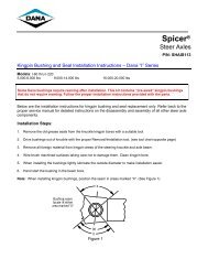
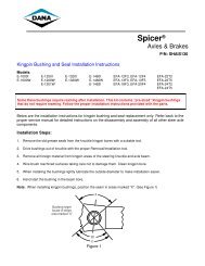
<strong>Spicer</strong> Axle <strong>Service</strong> and Maintenance Instructions<br />
Tandem Drive Axles<br />
Dual Range and Planetary Double Reduction Gearing<br />
Introduction<br />
Dana Corporation, Axle & Brake Division, presents this<br />
publication to aid in maintenance and overhaul of <strong>Spicer</strong><br />
tandem drive axles.<br />
<strong>Service</strong> and Maintenance instructions cover <strong>Spicer</strong> Dual<br />
Range (2-Speed) and Planetary Double Reduction Tandem<br />
Axles. Instructions are applicable to both gearing types<br />
unless specified otherwise.<br />
Five basic axle series are included in this book. Their design<br />
is common with differences in load capacity and two gearing<br />
types.<br />
Load<br />
Model Numbers<br />
Capacity Planetary<br />
(lbs.) Dual Range Double Reduction<br />
34,000 DT340, DT341 DP340, DP341<br />
38,000 DT380(P) DP380(P)<br />
38,000 * DT381(P) DP381(P)<br />
40,000 DT400-P, DT401-P DP400-P, DP401 -P<br />
40,000 DT402(P) DP402(P)<br />
45,000 DT451 -P DP451-P<br />
The suffix letter “P” in the Model No. indicates the axle<br />
is equipped with a gear-driven Lube Pump, designed to<br />
provide additional lubrication to the inter-axle differential<br />
and related parts.<br />
Instructions contained herein are applicable to all axle models<br />
unless specified otherwise.<br />
Typical Tandem Drive<br />
Axle (Dual Range illustrated).<br />
Design Variations:<br />
Two design variations of tandem<br />
axles are included in this manual.<br />
The major difference is in the shaft<br />
sp line design. Refer to page 5 for<br />
deails.<br />
For brake information and axle mounting suspension *NOTE: DS381 (P) axles manufactured<br />
systems, refer to pertinent truck manufacturer’s literature. after April 1985 are rated at 40,000 lbs,<br />
Contents<br />
Description and Operation<br />
● Disassemble Output Shaft<br />
Gearing and Torque Distribution<br />
● Assemble Output Shaft<br />
Lubrication<br />
● Assemble Inter-axle Differential<br />
Cleaning, Inspection, Replacement<br />
● Assemble Power Divider Cover<br />
Adjustments<br />
● Install Power Divider on Diff. Carrier<br />
• Wheel Bearings<br />
● Adjust Input Shaft End Play<br />
•Adjust Input Shaft End Play<br />
Differential Carrier Overhaul<br />
•Pinion Bearing Preload<br />
● Disassemble Differential Carrier<br />
•Differential Bearing Preload and<br />
● Disassemble Drive Pinion<br />
Ring Gear Backlash Adjustment<br />
• Disassemble Wheel Differential<br />
Ring Gear and Pinion Tooth Contact<br />
● Assemble Wheel Differential<br />
Fastener Tightening Specifications<br />
● Assemble Drive Pinion<br />
Rear Axle Differential<br />
● Forward Axle- Install Pinion<br />
Carrier Replacement<br />
● Forward Axle - Install Helical Gear<br />
Forward Axle Differential<br />
Carrier Replacement<br />
● Forward Axle - Install Differential<br />
Assembly in Carrier<br />
Power Divider Replacement<br />
● Rear Axle - Install Pinion and<br />
Power Divider Overhaul<br />
Differential in Carrier<br />
•Remove Power Divider<br />
from Differential Carrier<br />
•Disassemble power Divider Cover<br />
•Disassemble Inter-axle Differential<br />
Misc. Torque Fastening Chart<br />
DuaI Range Axle Shift System<br />
*<strong>Service</strong> Bulletin Supplement (Checking Input Shaft End Play — Axle Models with Thrust Button<br />
2 Price $3.50<br />
,
I<br />
Axle and Carrier Assembly Model Identification<br />
Axle Specification Number<br />
The complete axle is identified by the specification<br />
number stamped on the rear right-hand side of the<br />
axle. housing. This number identifies all component<br />
parts of the axle as built by <strong>Spicer</strong>, including special<br />
OEM requirements such as yoke or flange.<br />
In addition, some axles<br />
may include a metal<br />
identification tag (see<br />
illustration).<br />
Ring Gear and Drive Pinion<br />
are matched parts and must<br />
be replaced in sets. Check the<br />
appropriate <strong>Spicer</strong> Axle parts book<br />
for part numbers and ordering<br />
instructions.<br />
To aid in identifying gear sets, both<br />
parts are stamped with such information<br />
as number of pinion and<br />
ring gear teeth, individual part<br />
number and matched set number<br />
(refer to adjacent drawing).<br />
Metal Identification Tag<br />
Ring Gear and Pinion Identification<br />
<strong>Spicer</strong><br />
<strong>Spicer</strong> Axle<br />
<strong>Spicer</strong> Axle<br />
3
<strong>Spicer</strong> ¬<br />
Dual Range Tandem Drive Axles<br />
4<br />
Description and Operation<br />
<strong>Spicer</strong> Dual Range Tandems are<br />
basically 2-Speed, shiftable drive<br />
axles. They provide two gearing<br />
ratios (low and high ranges) and<br />
are designed for heavy-duty service<br />
in on-off highway operations. Low<br />
range for deep gear reduction and<br />
slow speed hauling off highway.<br />
High range for cruising speeds on<br />
highway.<br />
The complete tandem axle<br />
assembly includes two axle units,<br />
each with double gear reduction<br />
capability coupled by a 2-gear S Dual Range Gearing<br />
power divider.<br />
with Lube Pump<br />
Power Divider<br />
In operation, the power divider accepts the torque from the vehicle<br />
drivelne and distributes it equally to the two axles.<br />
This assembly is of the two-gear design consisting of an input shaft,<br />
inter-axle differential, output shaft and two constant-mesh helical<br />
gears.<br />
The inter-axle differential compensates for axle speed variations in the<br />
same way the wheel differential works between the two wheels of a<br />
single drive axle. This unit also acts as a central point in distribution<br />
of torque to the two axles.<br />
The power divider also includes a driver-controlled, air-operated<br />
lockout. When lockout is engaged, it mechanically prevents inter-axle<br />
differentiation for better performance under poor traction conditions.<br />
Lube Pump<br />
Tandem Axles with suffix letter "P" in Model No. are equipped with a<br />
lube pump to provide positive lubrication to the inter-axle differential<br />
and other power divider parts. This pump is operated by a drive gear<br />
engaged with the input shaft splines. When vehicle is moving in a<br />
forward direction, pressurized lube is delivered to the vital power<br />
divider parts.<br />
Dual Range Tandem Shift System<br />
Range selection is accomplished<br />
by an air shift system and is drivercontrolled<br />
through a cab-mounted<br />
air control valve.<br />
The control valve operates two<br />
shift units (one for each axle)<br />
which mechanically engages or<br />
disengages the planetary gearing.<br />
For operation description, refer<br />
to Shift System section in this<br />
manual.<br />
Lube Pump System<br />
The pump lube system<br />
incorporates a magnetic strainer<br />
screen. To keep the system clean,<br />
the magnet traps minute particles<br />
and the screen blocks out large<br />
particles of foreign material.<br />
Forward Axle Rear Ax/e<br />
Shift Unit Shift Unit
<strong>Spicer</strong> Planetary Double Reduction Axles<br />
Description and Operation<br />
The Planetary Double Reduction<br />
Tandem Axle shares its basic<br />
design concepts and many<br />
components with the Dual Range<br />
Tandem. The principle variation<br />
is the permanent engagement of<br />
the double reduction feature. A<br />
stationary sun gear, fixed in<br />
engagement with the low-speed<br />
clutch plate, replaces the sliding<br />
clutch gear and provides continuous<br />
double reduction operation in the<br />
same manner as the dual range<br />
axle when in Low Range.<br />
Torque distribution and power flow<br />
is same as Dual Range Gearing in<br />
Low Range (see page 7).<br />
Design Variations (Dual Range and Planetary Double Reduction Axles)<br />
NOTE: To assist in identifying the axle being serviced, here are the<br />
major design variations within the axle series covered by this manual.<br />
D341, 381(P)<br />
D340, 380(P) 401-P, 402(P),<br />
Axle Series<br />
400-P<br />
451-P<br />
Output Shaft Splines<br />
Side Gear End 16<br />
Output End 10<br />
Input Shaft Splines<br />
Input End 16<br />
Diff. End 36<br />
Helical Gear 7 pitch<br />
Drive Pinion Splines<br />
Forward Axle 10<br />
Rear Axle 10<br />
Drive Pinion Nut<br />
Forward Axle 1-1/2"-18<br />
self-locking<br />
Rear Axle 1-1/2"-18<br />
self-locking<br />
Axle Shaft &<br />
Side Gear Splines D340,380(P)-16<br />
D400-P-33<br />
16<br />
34<br />
44<br />
36<br />
5 pitch<br />
41<br />
39<br />
1-5/8"-18<br />
self-locking or<br />
slotted nut with<br />
roll pin M42 x 1.5<br />
after 7/1 /95<br />
1-1/2"-18<br />
self locking<br />
M36 x 1.5after<br />
7/1/95<br />
D341-39<br />
D381(P), D402(P) -41<br />
D401-R D451-P -33<br />
Lube Pump Drive Shaft. The drive shaft on early<br />
pump models is equipped with a woodruff key. On<br />
late pump models, the key is eliminated. The drive<br />
shaft end has two machined flats and the drive gear<br />
mounting hole is shaped to accommodate these flats.<br />
5
Gearing and Torque Distribution<br />
6<br />
Dual Range Gearing<br />
The gearing for each axle is a<br />
combination of a spiral bevel ring<br />
gear and pinion and a planetary<br />
unit.<br />
First reduction (High Range) is<br />
provided by the spiral bevel<br />
gearing.<br />
Second reduction (Low Range) is<br />
through the planetary gearing.<br />
Four planetary idler pinions are<br />
confined within the ring gear and<br />
mesh with the ring gear internal<br />
teeth. The planetary gears rotate<br />
around a sliding clutch gear.<br />
Each axle is equipped with a shift<br />
unit, which operates the sliding<br />
clutch gear to provide means for<br />
selecting the axle range. Range<br />
selection is accomplished through<br />
the movement of the sliding clutch<br />
gear in and out of engagement<br />
with low and high-speed clutch<br />
plates.<br />
Torque Distribution in High Range<br />
Torque (power flow) from the vehicle driveline is<br />
transmitted to the input shaft and the inter-axle<br />
differential spider. At this point, the differential<br />
distributes torque equally to both sides.<br />
For the forward axle, torque is transmitted from<br />
the helical-side gear to the pinion helical gear,<br />
drive pinion, ring gear, wheel differential and axle<br />
shafts.<br />
For the rear axle, torque is transmitted from the<br />
output shaft side gear, through the output shaft,<br />
inter-axle driveline, to the drive pinion, ring gear,<br />
wheel differential and axle shafts.<br />
The sliding clutch gear is locked<br />
into the high-speed clutch plate<br />
and rotates as part of the differential<br />
assembly. The planetary pinions<br />
are stationary and the axle<br />
uses only the single reduction of<br />
the ring gear and pinion. Power<br />
flow is through the drive pinion,<br />
ring gear, differential unit and axle<br />
shafts.<br />
The sliding clutch gear is shifted<br />
into engagement with the lowspeed<br />
clutch plate (an integral<br />
part of the bearing adjuster). The<br />
sliding clutch is held stationary and<br />
the planetary pinions are forced to<br />
rotate around it. Power flow is now<br />
through drive pinion, ring gear,<br />
planetary gearing, differential unit<br />
and axle shafts. The axle uses two<br />
reductions to multiply torque. The<br />
planetary unit adds approximately<br />
36¡/0 more reduction to the primary<br />
gear set. Torque is multiplied on<br />
an equivalent basis.<br />
INPUT<br />
TORQUE<br />
Torque is transmitted to both axles through inter-axle<br />
differential action.
Torque Distribution in High Range (cent’d)<br />
A lockout mechanism is incorporated in the power<br />
divider to enable the vehicle driver to lock out the INPUT<br />
inter-axle differential and provide maximum traction<br />
TORQUE<br />
under adverse road conditions.<br />
In operation, an air cylinder (controlled by a cabmounted<br />
valve) shifts a sliding clutch. To lock out<br />
inter-axle differential action, the clutch engages the<br />
helical-side gear and causes this gear, the input shaft<br />
and differential to rotate as one assembly. This action<br />
provides a positive drive to both axles.<br />
With lockout engaged, torque is distributed to both axles<br />
without differential action. The forward axle<br />
pinion and ring gear are driven by the helical-side<br />
gear. The rear axle gearing is driven from the output<br />
shaft side gear and inter-axle driveline.<br />
NOTE: Varied road surface conditions can result<br />
in unequal torque distribution between the two axle<br />
-<br />
assemblies.<br />
Torque Distribution in Low Range<br />
INPUT<br />
TORQUE<br />
Torque is transmitted to both axles without inter-axle<br />
differential action.<br />
INPUT<br />
TORQUE<br />
Torque is transmitted to both axles through inter-axle Torque is transmitted to both axles without inter-axle<br />
differential action. differential action.<br />
7
8<br />
<strong>Spicer</strong> Tandem Drive Axles<br />
Differential Carrier Assembly<br />
Forward Axle
Dual Range<br />
DT340, 310(P), 400-P<br />
DT341, 381(P), 401-P<br />
DT402(P), 451-P<br />
IMPORTANT: Seals,<br />
Yokes and Slingers.<br />
Before replacing<br />
these parts, refer to<br />
Repair and<br />
Replacement<br />
Instructions for<br />
interchangeability<br />
information.<br />
I<br />
Planetary Double Reduction<br />
DP340, 380(P), 400-P<br />
DP341, 381(P), 401-P<br />
DP402(P), 451-P<br />
9
<strong>Spicer</strong> ®<br />
Tandem Drive Axles<br />
10<br />
Differential Carrier Assembly<br />
Rear Axle<br />
Dual Range RT340, 341, 380, 381, 400, 401,402, 451<br />
Planetary Double Reduction RP340, 341, 380, 381, 400, 401, 402,451<br />
I
Lubrication<br />
The ability of a drive axle to deliver quiet, trouble-free<br />
operation over a period of years is largely dependent upon<br />
the use of good quality gear lubricant in correct quantity.<br />
The most satisfactory results can be obtained by following<br />
the directions contained in this manual.<br />
The following lubrication instructions represent the most<br />
current recommendations from the Axle & Brake Division of<br />
Dana Corporation.<br />
Approved Lubricants<br />
General-Gear lubrications acceptable under military<br />
specification (MILSPEC) MIL-L-2105D (Lubricating Oils,<br />
Gear, Multipurpose) are approved for use in <strong>Spicer</strong> Drive<br />
Axles. The MIL-L-2105D specification defines performance<br />
and viscosity requirements for multigrade oils. It supersedes<br />
both MIL-L-21 056, MIL-L-2105C and cold weather<br />
specification MlL-L-l 0324A. This specification applies to<br />
both petroleum-based and synthetic based gear lubricants<br />
if they appear on the most current “Qualified Products List”<br />
(QPL-2105) forMIL-L-2105D.<br />
Note: The use of separate oil additives and/or friction<br />
modifiers are not approved in Drive Axles.<br />
Synthetic based-Synthetic-based gear lubricants exhibit<br />
superior thermal and oxidation stability, and generally<br />
degrade at a lower rate when compared to petroleum-based<br />
lubricants. The performance characteristics of these lubricants<br />
include extended change intervals, improved fuel<br />
economy, better extreme temperature operation, reduced<br />
wear and cleaner component appearance. The family of<br />
<strong>Spicer</strong> ®<br />
gear lubricants represents a premium quality<br />
synthetic lube which fully meets or exceeds the<br />
requirements of MIL-L-2105D. These products, available in<br />
both 75W-90 and 80 W-1 40, have demonstrated superior<br />
performance in comparison to others qualified under the<br />
MILSPEC, as demonstrated by extensive laboratory and field<br />
testing. For a complete list of <strong>Spicer</strong>r ®<br />
approved synthetic<br />
lubricants contact your local <strong>Spicer</strong> representative. See<br />
back cover of this manual for appropriate phone number.<br />
Makeup Lube-Maximum amount of non-synthetic makeup<br />
lube is 100/o.<br />
Viscosity/Ambient Temperature Recommendations-The<br />
following chart lists the various SAE Grades covered by<br />
MIL-L-2105D and the associated ambient temperature range<br />
from each. Those SAE grades shown with an asterisk (*) are<br />
available in the <strong>Spicer</strong> family of synthetic gear lubricants.<br />
The lowest ambient temperatures covered by this chart are<br />
-40°F and -40°C. Lubrication recommendations for those<br />
applications which consistently operate below this temperature<br />
range, must be obtained through the Dana Corporation<br />
by contacting your local <strong>Spicer</strong> representative.<br />
Grade Ambient Temperature Range<br />
75W -40 o<br />
F to -15°F (-40 o<br />
C to -26 o<br />
C)<br />
75W-80 -40°F to 80 o<br />
F (-40°C to 21 o<br />
C)<br />
75W-90* -40 o<br />
F to 100 o<br />
F (-40 o<br />
C to 38 o<br />
C)<br />
75W-140 -40°F and above (-40 o<br />
C and above)<br />
80W-90 -15 0<br />
F to 100 o<br />
F (-26°C to -38 o<br />
C)<br />
80W-140* -15 0<br />
F and above (-26°C and above)<br />
85W-140 10 o<br />
F and above (-12°C and above)<br />
Lube Change Intervals<br />
This product combines the latest manufacturing and part<br />
washing technology. When filled with an approved<br />
synthetic lubricant at the factory, the initial drain is not<br />
required.<br />
Change the lubricant within the first 5,000 miles of<br />
operation when not using a approvedsynthetic<br />
lubricant in either a new axle or after a carrier<br />
head replacement. Base subsequent lubricant changes on<br />
a combination of the following chart and user assessment<br />
of the application and operating environment.<br />
Severe <strong>Service</strong> Lubrication Change Intervals - Severe<br />
service applications are those where the vehicle consistently<br />
operates at or near its maximum GCW or GVW<br />
ratings, dusty or wet environments, or consistent operation<br />
on grades greater than 8%. For these applications, the<br />
ON/OFF HIGHWAY portion of the chart should be used.<br />
Typical applications are construction, logging, mining and<br />
refuse removal.<br />
Note: Remove metallic particles from the magnetic filler<br />
plug and drain plugs. Clean or replace the breather at each<br />
lubricant change.<br />
I<br />
I Guidelines - Lube Change Intervals for Drive Axles I<br />
On Highway Maximum Change On/Off Highway Severe Maximum Change<br />
Lubricant Type Miles Interval <strong>Service</strong> Miles Interval<br />
Mineral 100,000 Yearly 40,000 Yearly<br />
Based<br />
<strong>Spicer</strong> - Approved 250,000 3 Years 100,000 Yearly<br />
Synthetic<br />
11
Lubrication<br />
12<br />
Changing Lube<br />
Draining<br />
Drain when the lube is at normal operating temperature. It will run freely<br />
and minimize the time necessary to fully drain the axle.<br />
Unscrew the magnetic drain plug on the underside of the axle housing<br />
and allow the lube to drain into a suitable container. Inspect drain plug<br />
for large quantities of metal particles. After initial oil change, these<br />
are signs of damage or extreme wear in the axle, and inspection of the<br />
entire unit may be warranted. Clean the drain plug and replace it after<br />
the lube has drained completely.<br />
Axles with Lube Pump: Remove the magnetic strainer from the power<br />
divider cover and inspect for wear material in the same manner as the<br />
drain plug. Wash the magnetic strainer in solvent and blow dry with<br />
compressed air to remove oil and metal particles.<br />
CAUTION: EXERCISE CARE TO DIRECT COMPRESSED AIR INTO<br />
SAFE AREA. WEAR SAFETY GLASSES.<br />
Filling<br />
Remove the filler hole plug from<br />
the center of the axle housing<br />
cover and fill the axle with<br />
approved lubricant until level<br />
with the bottom of the hole.<br />
Forward axles: Add two pints<br />
(0.94 liters) of lubricant through<br />
filler hole at the top of the differential<br />
carrier near the power<br />
divider cover.<br />
NOTE: Lube fill capacities in the<br />
adjacent chart are good guidelines<br />
but will vary somewhat on the<br />
basis of the angle the axle is<br />
installed in a particular chassis.<br />
Always use the filler hole as the<br />
final reference. If lube is level with<br />
the bottom of the hole, the axle is<br />
properly filled.<br />
Axle Installation Angles<br />
Axles installed at angles exceeding<br />
10 degrees or operated regularly<br />
in areas of continuous and lengthy<br />
grades may require standpipes to<br />
allow proper fill levels.<br />
For specific recommendations,<br />
contact your local <strong>Spicer</strong> representative.<br />
Lube Capacities*<br />
DO NOT OVERFILL AXLES<br />
Housings (Rectangular Arm)<br />
Dual Range and PDR Forward Rear<br />
Tandem Series Axle Axle<br />
Pints (liters) Pints (liters)<br />
340, 341 . . . . . . . . . . . . . . . . . . . . . . . . . . . 38 (18.0) 35 (16.6)<br />
380(P), 381 (P)<br />
400-P, 401-P<br />
402( P), 451-P . . . . . . . . . . . . . . . . . . . . . 37 (17.5) 34 (16.1)<br />
Forward Axles: Add an additional 2 pints (0.94 liters) axle lubricant<br />
through filler hole at the top of the differential carrier near the power<br />
divider cover. (See photo above.)<br />
*Capacities listed are approximate. The amount of lubricant will vary with angle of<br />
axle as installed in vehicle chassis. Figures do not apply to housings not designed<br />
or manufactured by <strong>Spicer</strong>.
Wheel End Lubrication<br />
IMPORTANT: In cases where wheel<br />
equipment is being installed, either new or<br />
after maintenance activity, the lube cavities<br />
are empty. Bearings and seals must be<br />
manually supplied with adequate lubricant<br />
or they will be severely damaged before the<br />
normal motion of the vehicle can supply<br />
lube to the hub ends of the housing.<br />
To avoid the risk of premature damage to being installed. There are three methods of<br />
wheel bearings and seals, they must be doing this. The correct method will depend<br />
“prelubed” any time the wheel equipment is on the type of wheel equipment being used.<br />
Lubrication When Hubs Have No Filler Holes (Preferred Method*)<br />
(Follow procedure in numerical sequence.)<br />
1. Fill axle with lube through axle housing cover filler hole.<br />
2. Jack up left side of axle.<br />
Maintain this position for<br />
one minute to allow lube to<br />
flow into wheel ends at<br />
right side.<br />
3. Jack up right side of<br />
axle. Maintain this position<br />
for one minute to allow<br />
lube to flow into wheel<br />
ends at left side.<br />
4. With vehicle level again, add lube<br />
through axle housing cover filler hole. The<br />
axle should require two additional pints of<br />
lube to bring level up to bottom of filler hole.<br />
*The above procedure is the preferred method since it optimizes the lube supply to the<br />
wheel end components and axle sump.<br />
Alternate Method of Wheel End Lubrication<br />
1. After the wheel hub seal has been installed, prepacked with a good quality grease instead<br />
charge the hub cavity with as much axle of axle lube. However, excess grease should<br />
lubricant as possible. be removed.<br />
2. Prelube the bearings with clean axle<br />
lubricant at installation.<br />
CAUTION: Exercise caution when<br />
mounting a precharged hub and drum<br />
NOTE: If the hub has no cavity to accept a assembly to prevent spilling lubricant on<br />
precharge of axle lube, the bearings can be the brake linings.<br />
Hubs Equipped with Lube Filler Holes<br />
Pour a pint of standard axle lubricant into<br />
the hub through the cavity filler hole<br />
provided.<br />
13
Cleaning, Inspection, Replacement<br />
14<br />
As the drive axle is disassembled, set all parts aside for thorough<br />
cleaning and inspection. Careful inspection will help determine whether<br />
parts should be reused. In many cases, the causes of premature wear or<br />
drive axle failure will also be revealed.<br />
Cleaning<br />
The differential carrier assembly may be steam-cleaned while mounted in<br />
the housing as long as all openings are tightly plugged. Once removed<br />
from its housing, do not steam clean differential carrier or any components.<br />
Steam cleaning at this time could allow water to be trapped in<br />
cored passages, leading to rust, lubricant contamination, and premature<br />
component wear. The only proper way to clean the assembly is to disassemble<br />
it completely. Other methods will not be effective except as<br />
preparatory steps in the process. Wash steel parts with ground or polished<br />
surfaces in solvent. There are many suitable commercial solvents available.<br />
Kerosene and diesel fuel are acceptable.<br />
WARNING: GASOLINE IS NOT AN ACCEPTABLE SOLVENT BECAUSE<br />
OF ITS EXTREME COMBUSTIBILITY. IT IS UNSAFE IN THE<br />
WORKSHOP ENVIRONMENT.<br />
Wash castings or other rough parts in solvent or clean in hot solution<br />
tanks using mild alkali solutions. If a hot solution tank is used, make<br />
sure parts are heated thoroughly, before rinsing.<br />
Rinse thoroughly to remove all traces of the cleaning solution. Dry parts<br />
immediately with clean rags.<br />
Lightly oil parts if they are to be reused immediately. Otherwise, coat<br />
with oil and wrap in corrosion-resistant paper. Store parts in a clean, dry<br />
place.<br />
Inspection<br />
Inspect steel parts for notches, visible steps or grooves created by wear.<br />
Look for pitting or cracking along gear contact lines. Scuffing, deformation<br />
or discoloration are signs of excessive heat in the axle, usually<br />
related to low lubricant levels or improper lubrication practices.<br />
Before reusing a gear set, inspect teeth for signs of excessive wear.<br />
Check tooth contact pattern for evidence of incorrect adjustment (see<br />
Adjustment Section for correct pattern).<br />
Inspect machined surfaces of cast or malleable parts. They must be free<br />
of cracks, scoring, and wear. Look for elongation of drilled holes, wear<br />
on surfaces machined for bearing fits and nicks or burrs in mating<br />
surfaces.<br />
Inspect fasteners for rounded heads, bends, cracks or damaged threads.<br />
The axle housing should be examined for cracks or leaks. Also look for<br />
loose studs or cross-threaded holes.<br />
Inspect machined surfaces for nicks and burrs.<br />
“
Repair and Replacement<br />
IMPORTANT: To achieve maximum value from an axle rebuild, replace<br />
lower-cost parts, such as thrust washers, seals, etc. These items protect<br />
the axle from premature wear or loss of lubricants. Replacing these<br />
parts will not increase rebuild cost significantly.<br />
It is also important to replace other parts which display signs of heavy<br />
wear even though not cracked or broken. A significant portion of such a<br />
part’s useful life has been expended and the damage caused, should the<br />
part fail, is far in excess of its cost.<br />
Steel Parts — Gear sets, differential parts and bearings are not repairable.<br />
Worn or damaged parts should be discarded without hesitation.<br />
Also discard mating parts in some cases. Gear sets for example,<br />
must be replaced in sets.<br />
Miscellaneous Parts — Seals and washers are routinely replaced. None<br />
of these parts can be reused if damaged. Fasteners using self-locking<br />
nylon “patches” may be reused if not damaged, but should be secured<br />
by a few drops of Loctite #277 on the threaded surface of the hole during<br />
installation and carefully torqued during installation.<br />
Axle Housings — Repairs are limited to removal of nicks or burrs on<br />
machined surfaces and the replacement of loose or broken studs.<br />
CAUTION: ANY DAMAGE WHICH AFFECTS THE ALIGNMENT OR<br />
STRUCTURAL INTEGRITY OF THE HOUSING REQUIRES HOUSING<br />
REPLACEMENT. REPAIR BY WELDING OR STRAIGHTENING<br />
SHOULD NOT BE ATTEMPTED. THIS PROCESS CAN AFFECT THE<br />
HOUSING HEAT TREATMENT AND CAUSE IT TO FAIL COMPLETELY<br />
WHEN UNDER LOAD.<br />
Silicone Rubber Gasket Compound — For more effective sealing, <strong>Spicer</strong><br />
uses silicone rubber gasket compound to seal the majority of metal-tometal<br />
mating surfaces.<br />
<strong>Spicer</strong> includes gasket compound and application instructions in many<br />
repair parts kits.<br />
It is recommended that this compound be used in place of conventional<br />
gaskets. The compound will provide a more effective seal against lube<br />
seepage and is easier to remove from mating surfaces when replacing<br />
parts.<br />
Seals, Yoke & Slinger <strong>Service</strong> Information<br />
During the 4th Quarter of 1990, <strong>Spicer</strong> began using new seals and yoke & slingers on the models in this<br />
publication. The new seals and slingers are noticeably different from the current seals and will affect<br />
interchangeability.<br />
● The upgraded Seals can be used on axles originally equipped with the old seals.<br />
● <strong>Spicer</strong> recommends the replacement of old yoke & slinger assemblies when the new seals are installed. The<br />
old yokes and slingers will work with the new seals, but new yoke and slinger assemblies provide maximum<br />
sealing protection and prevent premature seal wear due to poor yoke condition.<br />
● New yoke and slinger assemblies cannot be used with the old seal design on the tandem forward axles.<br />
● New yoke and slinger assemblies can be used with the old seal on the tandem rear pinions.<br />
● Yoke Assembly & Oil Seal Kits contain oil seal, yoke & slinger and instructions.<br />
● Most non-<strong>Spicer</strong> aftermarket seals will not be compatible with the new <strong>Spicer</strong> Yoke and Slinger assemblies.<br />
● Sicer recommends the use of special installation tools conveniently packaged in a single kit (listed below).<br />
• Refer to <strong>Spicer</strong> parts Book AXIP-0087 and <strong>Spicer</strong> Bulletin 90-06 for additional information.<br />
Seal Driver Installation Kit 212139<br />
Includes:<br />
• 126917 Driver (Rear Axle Pinion)<br />
• 127787 Adapter (use with 126917 Driver for Forward Axle Input)<br />
• 127786 Driver (Forward Axle Output)<br />
15
Adjustments<br />
Wheel Bearing Adjustment<br />
Wheel bearings should be adjusted at regular intervals<br />
using the following procedure:<br />
Wheel End Seal<br />
WARNING: Never work under<br />
a vehicle supported by<br />
only a jack. Always support<br />
vehicle with stands. Block<br />
the wheels and make sure<br />
the vehicle will not roll before<br />
releasing the brakes<br />
Important: Wheel end seals can be easily damaged during handling. Leave the seal in its package until installation to<br />
prevent damage or contamination.<br />
1. Remove:<br />
● The outer bearing and wheel.<br />
● The inner bearing.<br />
● The oil seal or grease retainer and discard.<br />
● The old wear sleeve (2-piece design only) with a ball peen hammer and discard.<br />
Caution: Do not cut through the old wear sleeve. Damage to the housing may result.<br />
2. Inspect:<br />
● The spindle journal and hub bore for scratches or burns. Recondition with emery cloth as required.<br />
Note: Deep gouges can be repaired by filling gouge with hardened gasket and smoothing with emery cloth.<br />
3. Clean<br />
● The hub cavity and bearing bores before reassembly. Be sure to remove contaminants from all recesses and corners.<br />
● The bearings thoroughly with solvent and examine for damage. Replace damaged or worn bearings.<br />
4. Before installation, lubricate with the same lubricant used in the axle sump.<br />
● The inner bearing.<br />
● The wheel seal following the directors provided by the seal supplier.<br />
IMPORTANT: Always use the seal installation tool specified by the seal manufacturer. Using an improper tool<br />
can distort or damage the seal and cause premature seaI failure.<br />
Wheel Bearing Adjustment<br />
1. Identify the wheel nut system being installed. Three systems are available:<br />
● Three piece Dowel-type wheel nut system-fig.1<br />
● Three piece Tang-type wheel nut system-Fig.2<br />
● Four piece Tang/Dowel type wheel nut system-Fig.3<br />
WARNING: Do not mix spindle nuts and lock washers from different systems. Mixing spindle nuts and lock washers can<br />
cause wheel separation.<br />
NOTE: The lock washer for a four piece-dowel-type wheel system is thinner than the lock washer for a three piece tangtype<br />
wheel nut system and is not designed to bear against the inner nut.<br />
16<br />
J
2. inspect the indle and nut threads for corrosion and ean thoroughly or replace as required.<br />
Note: Proper assembly and adjustment is not possible if the spindle or nut threads are corroded.<br />
● Inspect the tang-type washer (if used). Replace the washer if the tangs are broken, cracked, or damaged.<br />
3. Install the hub and drum on the spindle with care to prevent damage or distortion to the wheel seal.<br />
* CAUTION: A wheel dolly is recommended during installation to make sure that the wheel seal is not damaged<br />
by the weight of the hub and drum. Never support the hub on the spindle with just the inner bearing and seal.<br />
This can damage the seal and cause premature failure.<br />
● Completely fill the hub cavity between the inner and outer bearing races with the same lubricant used in the axle sump.<br />
4. Before installation, lubricate the outer bearing with the same lubricant used in the axle sump.<br />
Note: Lubricate only with clean axle lubricant of the same type used in the axle sump. Do not pack the bearing with<br />
grease before installation. Grease will prevent the proper circulation of axle lubricant and may cause wheel seal failure.<br />
5. ● Install the outer bearing on the spindle.<br />
● Install the inner nut on the spindle.<br />
● Tighten the inner nut to 200 lbs. ft. (271 N. M.) while rotating the wheel hub.<br />
* CAUTION: Never use an impact Wrench to adjust wheel bearings. A torque wrench is required to assure that<br />
the nuts are property tightened.<br />
6.<br />
7.<br />
8.<br />
Back-off the inner nut one full turn. Rotate the wheel hub.<br />
Re-tighten the inner nut to 50 lbs. ft. (68 N. M.) while rotating the wheel hub.<br />
Back-off the inner nut exactly 1/4 turn.<br />
Note: This adjustment procedure allows the wheel to rotate freely with 0.001”-0.005” (0.025mm to 0.1 27mm) end-play.<br />
9. Install the correct lock washer for the wheel nut system being used.<br />
THREE PIECE TANG-TYPE LOCK WASHER SYSTEM (see Fig. 2).<br />
*Install the Tang-type lock washer on the spindle.<br />
IMPORTANT: Never tighten the inner nut for alignment. This can preload the bearing and cause premature failure.<br />
*Install the outer nut on the spindle and tighten to 250 lbs. ft. (339 N.M.).<br />
*Verify end-play (see End Play Verification Procedure)<br />
*After verifying end play, secure wheel nuts by bending one of the locking<br />
washer tangs over the outer wheel nut and another tang over the inner wheel<br />
nut as shown in Figure 4. (below)<br />
THREE PIECE DOWEL-TYPE LOCK WASHER SYSTEM (see Fig.1)<br />
* Install the Dowel-type lock washer on the spindle.<br />
Note: If the dowel pin and washer are not aligned, remove washer, turn it over<br />
and reinstall. If required, loosen the inner nut just enough for alignment.<br />
IMPORTANT: Never tighten the inner nut for alignment. This can preload the bearing and cause premature failure.<br />
*Install the outer nut on the spindle and tighten to 350 lbs. ft. (475 N.M.).<br />
*Verify end-play (see End Play Verification Procedure)<br />
17
FOUR PIECE TANG/DOWEL-TYPE LOCK WASHER SYSTEM (see Fig. 3)<br />
* First, install the Dowel-type lock washer on the spindle.<br />
Note: If the dowel pin and washer are not aligned, remove washer, turn it over and reinstall. If required loosen the inner<br />
nut just enough for alignment.<br />
IMPORTANT: Never tighten the inner nut for alignment. This can preload the bearing and cause premature failure.<br />
* Install the Tang-type lock washer on the spindle.<br />
* Install the outer nut on the spindle and tighten to 250 lbs. ft. (339 N m.)<br />
* Verify end-play (see End Play Verification Procedure)<br />
* After verifying end play, secure the outer nut by bending two opposing (180ç apart) tangs of the locking washer<br />
over the outer nut as shown in Figure 5 (below).<br />
10. Install<br />
* New gasket at axle shaft flange.<br />
* axle shaft.<br />
* Axle flange nuts and tighten to specified torque.<br />
11. Lubricate axle wheel ends (see Wheel End Lubrication Procedure)<br />
End Play Verification Procedure<br />
Verify that end-play meets specification using a dial indicator. An indicator<br />
with 0.001" (0.03 mm) resolution is required. Wheel end play is the<br />
free movement of the tire and wheel assembly along the spindle axis.<br />
a. Attach a dial indicator with its magnetic base to the hub or brake drum as shown below:<br />
With indicator mounted at bottom,<br />
Push/Pull at sides of drum<br />
End Play Adjustment<br />
with Wheel hub<br />
Fig. 4 End Play Measurement<br />
b. Adjust the dial indicator so that its plunger or pointer is against the end of the spindle with its line of action approximately<br />
parallel to the axis of the spindle.<br />
c. Grasp the wheel assembly at the 3 o'clock and 9 o'clock positions. Push the wheel assembly in and out while<br />
oscillating it to seat the bearings. Read bearing end play as the total indicator movement.<br />
* CAUTION: If end play is not within specification, readjustment is required.<br />
End Play Re-adjustment Procedure<br />
Excessive End Play - If end play is greater than .005' (.127 mm), remove the outer nut and pull the lock washer away<br />
from the inner nut, but not off the spindle. Tighten the inner nut to the next alignment hole of the dowel-type washer (if<br />
used). Reassemble the washer and torque the outer nut. Verify end play with a dial indicator.<br />
Insufficient End Play - If end play is not present, remove the outer nut and pull the lock washer away from the inner<br />
nut, but not off the spindle. Loosen the inner nut to the next adjustment hole of the dowel-type washer (if used). Reassemble<br />
the washer and re-torque the outer nut. Verify end play with a dial indicator.<br />
Fine Tuning the End Play - If, after performing the readjustment procedures, end play is still not within the .001"-.005"<br />
(.025 mm to.127 mm) range, disassemble and inspect the components. If parts are found to be defective, replace the<br />
defective parts, reassemble and repeat wheel bearing adjustment procedure. Verify end play with a dial indicator.<br />
18<br />
I
I<br />
Differential Carrier<br />
Adjustments help provide optimum axle life and performance by correctly<br />
positioning bearings and gears under load.<br />
The tandem axles covered in this manual require the following adjustments:<br />
Bearing Preload: This adjustment is Ring Gear Tooth Contact: This adjust- Input Shaft End Play (Forward Axles):<br />
performed for both pinion and differ- ent positions ring gear and pinion This adjustment controls gear mesh<br />
ential bearings. It maintains proper for best contact under load. Correct in the inter-axle differential. Proper<br />
gear alignment by creating correct adjustment distributes torque evenly adjustment helps maximize life of all<br />
bearing cone and cup relationship for over gear teeth and helps maximize power divider parts.<br />
free rotation under load. The pinion gear set life.<br />
pilot bearing does not require a preload<br />
adjustment.<br />
Adjust Input Shaft End Play<br />
Specifications: Input shaft end play requirements will vary with operating<br />
conditions, mileage and rebuild procedures. These variations are<br />
shown in the following chart.<br />
Input Shaft End Play Chart<br />
New or Rebuild with new parts NOTE: Because of manufacturing<br />
0.003" to 0.007" variations in individual parts,<br />
correctly adjusted end play could<br />
Rebuild with reused parts vary 0.010", after the unit is<br />
0.013" to 0.017" rotated.<br />
Acceptable End Play Tolerances when measuring as<br />
a regular maintenance procedure with axle in truck.<br />
Up to 0.060" with over 100,000 NOTE: If end play exceeds limits,<br />
miles or 1 year service off-road. disassemble power divider and<br />
replace worn parts.<br />
Up to 0.040" with less than 100,000<br />
miles or 1 year service on-road.<br />
Measure and Adjust End Play<br />
IMPORTANT: In September 1988, <strong>Spicer</strong> added a Spring and a Thrust<br />
Button between the input and output shafts. End play tolerances are the<br />
same for axles with or without this Spring and Button. However, end play<br />
measurement procedure is different than-described below. Refer to <strong>Service</strong><br />
Bulletin Supplement at back of this manual for procedure variances.<br />
1. With power divider assembled to differential carrier, measure end<br />
pay with dial indicator positioned at yoke end of input shaft. Move<br />
input shaft axially and measure end play. If end play is not correct (see<br />
chart), adjust as follows.<br />
2. Remove input shaft nut, flat washer and yoke. Remove bearing cover<br />
cap screws and lockwashers. Remove cover and shim pack.<br />
3. To increase end play, add shims:<br />
desired end play . . . . . . . . . . . . . . . . . . . . . . . . . . . . . . . . 0.003" to 0.007"<br />
pleasured endplay (Step)....... . . . . . . . . . . . . . . . . 0.001" - 0.001"<br />
Add shims to provide desired end play . . . . . . . . . . . . . 0.002" to 0.006"<br />
4. To decrease end play, remove shims:<br />
Measured endplay (Step 1l) . . . . . . . . . . . . . . . . . . . . . . . 0.015" - 0.015"<br />
desired end play . . . . . . . . . . . . . . . . . . . . . . . . . . . . . . . . 0.003" to 0.007"<br />
Remove shims to provide desired end play . . . . . . . . . 0.012" to 0.008"<br />
5. To reassemble input shaft, install the adjusted shim pack and bearing<br />
cover. Install cap screws and lockwashers. Torque screws to 75-85<br />
ft-lbs. (101-115 N.m).<br />
NOTE: If difficulty is experienced in achieving correct torque on the<br />
input yoke nut, torque the nut with truck on the ground and axle shafts<br />
installed.<br />
6. Install yoke, flat washer and nut.<br />
Tighten nut snugly. Tap end of<br />
input shaft lightly to seat bearings.<br />
7. Measure input shaft end play<br />
with dial indicator. If end play is<br />
still incorrect, repeat Steps 2<br />
through 6.<br />
8. With end play correct, seal shim<br />
pack to prevent lube Ieakage, then<br />
torque input shaft nut and cover<br />
cap screws (see chart).<br />
NOTE: When power divider has<br />
been disassembled and reassembled,<br />
it may be desirable to adjust<br />
end play by measuring bearing<br />
cover clearance and calculating<br />
shim pack size. For procedures,<br />
see page 42.<br />
Torque Chart<br />
Input<br />
Shaft Nut Ft-lbs. N´m<br />
1-5/8-18 780-960 1057-1301<br />
*M42 X 1.5<br />
Bearing Cover<br />
Cap Screw<br />
840-1020 1140-1383<br />
1/2-13<br />
(Grade 5)<br />
75-85 101-115<br />
*Metric Nut used on Axles produced after 7/1 /95<br />
19
Adjustments<br />
I<br />
20<br />
Pinion Bearing Preload<br />
Most late model axles are provided with a “press-fit” outer bearing on<br />
the drive pinion. Some of the early model axles use an outer bearing<br />
which slips over the drive pinion. Procedures for adjusting both types<br />
of pinion bearing design are contained in this section.<br />
Adjust Pinion Bearing Preload for Axles with<br />
.<br />
“Press-fit” Outer Pinion Bearings<br />
Trial Build-up<br />
1. Assemble pinion bearing cage,<br />
bearings and spacer (without drive<br />
pinion or oil seal). Center bearing<br />
spacer between two bearing cones.<br />
NOTE: When new gear set or<br />
pinion bearings are used, select<br />
nominal size spacer from the specification<br />
chart below. If original<br />
parts are used, use spacer removed<br />
during disassembly.<br />
2. With the bearings well lubricated,<br />
place the assembly in the<br />
press. Position sleeve so that load<br />
is applied directly to the back-face<br />
of the outer bearing cone.<br />
3. Apply press load (see chart<br />
below) to the assembly and check<br />
rolling torque. Wrap soft wire<br />
around the bearing cage, attach<br />
spring scale and pull. Preload is<br />
correct when torque required to<br />
rotate the pinion bearing cage is<br />
from 10-20 inch-pounds. This<br />
specification is translated into<br />
spring scale readings in the chart<br />
below.<br />
4. If necessary, Adjust Pinion<br />
Bearing Preload by changing the<br />
pinion bearing spacer. A thicker<br />
spacer will decrease preload. A<br />
thinner spacer will increase<br />
preload.<br />
IMPORTANT: Once correct bearing<br />
preload has been established,<br />
note the spacer size used. Select a<br />
spacer 0.001” larger for use in the<br />
final pinion bearing cage assembly.<br />
The larger spacer compensates<br />
for slight “growth” in the bearings<br />
which occurs when they are<br />
pressed on the pinion shank. The<br />
trial build-up will result in proper<br />
pinion bearing preload in three<br />
of four cases.<br />
IMPORTANT: Do not assume that<br />
all assemblies will retain proper<br />
preload once bearings are pressed<br />
on pinion shank. FINAL PRELOAD<br />
TEST MUST BE MADE IN EVERY<br />
CASE.<br />
Assemble these Parts for<br />
Trial Build-up.<br />
INNER INNER BEARING OUTER OUTER<br />
BEARING BEARING SPACER BEARING BEARING<br />
CONE CUP (vARIABLE) CUP CONE<br />
Specifications for Pinion Bearing Spring<br />
Trial Build-up Preload Test<br />
(“Press-fit” Outer Pinion Bearings)<br />
Scale Reading<br />
(without<br />
pinion seal)<br />
(for 10-20<br />
Nominal Bearing<br />
Spacer Thickness Press Loads<br />
in-lbs. torque)<br />
(1.1-2.3 Nm)<br />
Axle Models<br />
Forward Axles<br />
in. mm Tons Metric Tons lbs. kgs.<br />
D340, 380(P),<br />
400-P<br />
D341, 381(P),<br />
0.638 16.21 13.5-15.5 12.2-14.0 3-7 1.4-3.2<br />
401-P, 402(P),<br />
451-P 0.496 12.60 17-19 15.4-17.2 3-7 1.4-3.2<br />
Rear Axles<br />
(ail models) 0.638 16.21 14-15 12.7-13.6 4-8 1.8-3.6
Final Pinion Bearing Preload Test<br />
1. Assemble the complete pinion bearing cage unit as recommended<br />
in the assembly section of this manual.<br />
NOTE: Forward axle pinion is equipped with helical gear. For easier<br />
disassembly during bearing adjustment procedure, use a dummy yoke<br />
if available) in place of helical gear.<br />
.2. Apply clamp load to the pinion bearing cage assembly. Either install<br />
the yoke (or helical gear) and torque the pinion nut to specifications or<br />
use a press to simulate nut torque (see chart below).<br />
Vise Method - If the yoke and nut are used, mount the assembly in a<br />
vise, clamping yoke firmly.<br />
Press Method - If a press is used, position a sleeve or spacer so that<br />
load is applied directly to the back-face of the outer bearing cone.<br />
.3. Measure Pinion Bearing Preload - Use a spring scale to test the<br />
assembly rolling torque. To use the spring scale, wrap soft wire around<br />
the bearing cage, attach the scale and pull. Preload is correct when<br />
torque required to rotate the pinion bearing cage is from 15 to 35 inch<br />
pounds. This specification is translated into spring scale readings in the<br />
chart below.<br />
4. Adjust Pinion Bearing Preload - If necessary, adjust pinion bearing<br />
preload. Disassemble the pinion bearing cage as recommended in this<br />
manual and change the pinion bearing spacer. A thicker spacer will<br />
decrease preload. A thinner spacer will increase preload.<br />
IMPORTANT: Use the correctly sized spacer. Do not use shim stock or<br />
grind spacers. These practices can lead to loss of bearing preload and<br />
gear or bearing failure.<br />
Specifications for Final Pinion<br />
Spring Scale Reading<br />
Bearing Preload Test<br />
(without pinion seal)<br />
("Press-fit" Outer Pinion Bearing)<br />
(for 15-35 in-lbs. torque)<br />
Nut Torque Press Loads<br />
(1.7-4 N.m)<br />
Axle Models Ft-lbs. N.m Tons Metric Tons lbs. kgs.<br />
Forward Axles SELF-LOCKING NUT<br />
D340, 380(P),<br />
400-P 560-700 759-949 13.5-15.5 12.2-14.0 5-12 2.3-5.4<br />
D341, 381(P), SELF-LOCKING NUT<br />
401-P, 402(P), 780-960 1057-1301 17-19 15.4-17.2 5-12 2.3-5.4<br />
451 -P SLOTTED NUT & ROLL PIN<br />
840* 1139* 17-19 15.4-17.2 5-12 2.3-5.4<br />
METRIC NUT (After 7-1-95)<br />
840-1020 1140-1383 17-19 15.4-17.2<br />
Rear Axles<br />
(all models) 560-700 759-949 14-15 12.7-13.6 6-14 2.7-6.4<br />
METRIC NUT (After 7-1-95)<br />
575-703 774-955<br />
*Torque nut to 840 ft-lbs. (1139 N´m), then continue tightening nut to align nut slot to nearest hole in pinion shank.<br />
21
Adjustments<br />
22<br />
Adjust Pinion Bearing Preload for Axles with<br />
ñSlip-fitî Outer Pinion Bearings<br />
1. Lubricate bearings and assemble the drive pinion, bearings, and<br />
pinion bearing cage as recommended in the assembly section of this<br />
manual. Use the pinion bearing spacer removed from the axle during<br />
disassembly. If the original spacer cannot be used, install the nominal<br />
spacer recommended in the adjacent chart.<br />
NOTE: Forward axle pinion is equipped with helical gear. For easier<br />
disassembly during bearing adjustment procedure, use a dummy yoke<br />
(if available) in place of helical gear.<br />
2. Apply clamp load to the pinion bearings. Install the yoke (or helical<br />
gear) and torque the nut to specification or use a press to simulate nut<br />
torque by applying pressure to the assembly (see chart below).<br />
Vise Method - If the yoke and nut are used, mount the assembly<br />
in a vise, clamping yoke firmly.<br />
Press Method - If a press is used, position a sleeve or spacer so that<br />
load is applied directly to the back-face of outer pinion bearing.<br />
3. Measure Pinion Bearing Preload - Use a spring scale to test the<br />
assembly rolling torque. To use the spring scale, wrap a soft wire around<br />
the bearing cage, attach the scale and pull. Preload is correct when<br />
torque required to rotate the pinion bearing cage is from 15 to 35 inch<br />
pounds. This specification is translated into spring scale readings in the<br />
chart below.<br />
4. Adjust Pinion Bearing Preload - If necessary, adjust pinion bearing<br />
preload. Disassemble the pinion bearing cage as recommended in this<br />
manual and change the pinion bearing spacer. A thicker spacer will<br />
decrease preload. A thinner spacer will increase preload.<br />
IMPORTANT: Use the correctly sized spacer. Do not use shim stock or<br />
grind spacers. These practices can lead to loss of bearing preload and<br />
gear or bearing failure.<br />
Axle Models<br />
Forward Axles<br />
D340, 380(P),<br />
400-P<br />
D341, 381 (P),<br />
401-P, 402(P),<br />
451-P<br />
Rear Axles<br />
(all models)<br />
Specifications for Final Pinion<br />
Bearing Preload Test<br />
("Press-fit" Outer Pinion Bearing)<br />
I<br />
Nut Torque Press Loads<br />
Ft-lbs. N.m Tons Metric Tons<br />
SELF-LOCKING NUT<br />
560-700 759-949 13.5-15.5 12.2-14.0<br />
SELF-LOCKING NUT<br />
780-960 1057-1301 17-19 15.4-17.2<br />
SLOTTED NUT & ROLL PIN<br />
840* 11 39* 17-19 15.4-17.2<br />
METRIC NUT (After 7-1-95)<br />
840-1020 1140-1383 17-19 15.4-17.2<br />
560-700 759-949 14-15 12.7-13.6<br />
METRIC NUT (After 7-1-95)<br />
575-703 774-955<br />
*Torque nut to 840 ft-lbs. (1.139 N´m), then continue tightening nut to align nut slot to nearest hole in pinion shank.<br />
Nominal Pinion<br />
Bearing Spacers<br />
Spacer Thickness<br />
Axle Model in. mm<br />
Forward Axles<br />
D340, 380(P), 400-P 0.638 16.205<br />
D341, 381(P), 401-P,<br />
402(P), 451-P 0.492 12.497<br />
Rear Axles<br />
(all models) 0.638 16.205<br />
Measuring Bearing Preload with<br />
Pinion in Vise.<br />
Measuring Bearing Preload with<br />
Pinion in Press.<br />
Spring Scale Reading<br />
(without pinion seal)<br />
(for 15-35 in-lbs. torque)<br />
(1.7-4 N.m)<br />
lbs. kgs.<br />
5-12 2.3-5.4<br />
5-12 2.3-5.4<br />
5-12 2.3-5.4<br />
6-14 2.7-6.4
Differential Bearing Preload and Ring Gear<br />
Backlash Adjustment<br />
Correct differential bearing preload insures proper location of these<br />
bearings under load and helps position the ring gear for proper gear<br />
tooth contact.<br />
(Follow procedures in numerical sequence.)<br />
Adjust Diff. Bearing Preload<br />
1. Lubricate differential bearings. NOTE: Ring gear position for rear 3. Loosen the bearing adjuster<br />
IMPORTANT: When installing axle is illustrated. on the same side as the ring gear<br />
bearing caps and adjuster, exert<br />
teeth until its first thread is<br />
care not to cross threads.<br />
visible.<br />
/<br />
2. Install adjusters and bearing<br />
caps. Tighten bearing cap screws /<br />
finger-tight. If this is difficult,<br />
use a hand wrench.<br />
4. Tighten the bearing adjuster<br />
on the back-face side of the ring<br />
gear until there is no backlash.<br />
This can be tested by facing the<br />
ring gear teeth and pushing the<br />
gear away from the body while<br />
gently rocking the gear from side<br />
to side. There should be no free<br />
movement.<br />
Rotate the ring gear and check<br />
for any point where the gear may<br />
bind. If such a point exists,<br />
loosen and retighten the back<br />
side adjuster. Make all further<br />
adjustments from the point of<br />
tightest mesh.<br />
Adjust Ring Gear Backlash<br />
To add backlash: Loosen the<br />
adjuster on the teeth side of the ring<br />
gear several notches. Loosen the<br />
opposite adjuster one notch.<br />
Return to adjuster on teeth side of<br />
the ring gear and tighten adjuster<br />
until it contacts the bearing cup.<br />
Continue tightening the same adjuster<br />
2 or 3 notches. Recheck<br />
backlash.<br />
5. At teeth side of ring gear,<br />
tighten adjuster until it contacts<br />
the bearing cup. Continue tightening<br />
adjuster two or three notches<br />
and this will preload bearings and<br />
provide backlash.<br />
6. Measure backlash with a dial indicator.<br />
USED GEARING — Reset to backlash recorded before disassembly.<br />
NEW GEARING — Backlash should be between 0.006” and 0.016”.<br />
If backlash is incorrect, proceed as described below to readjust.<br />
To remove backlash: Loosen the<br />
adjuster on the teeth side of the ring<br />
gear several notches. Tighten the<br />
opposite adjuster one notch.<br />
Return to adjuster on teeth side of<br />
ring gear and tighten adjuster until it<br />
contacts the bearing cup. Continue<br />
tightening the same adjuster 2 or 3<br />
notches. Recheck backlash.<br />
Moving adjuster one notch is the<br />
movement of the lead edge of one<br />
adjuster lug to the lead edge of the<br />
next lug past a preselected point.<br />
23
Adjustments<br />
24<br />
R ing Gear and Pinion Tooth Contact<br />
NOTE: Rear axle gearing is shown in the following instructions. Correct<br />
tooth contact patterns and adjustments are the same for forward and<br />
rear axles.<br />
Check Tooth Contact Pattern (NEW GEAR)<br />
Paint twelve ring gear teeth with marking compound<br />
and roll the gear to obtain a contact pattern. The correct<br />
pattern is well-centered on the ring gear tooth with<br />
lengthwise contact clear of the to the Iength of the<br />
pattern in an unloaded condition is approximately onehalf<br />
to two-thirds of the ring gear tooth in most models<br />
and ratios.<br />
RING GEAR TOOTH NOMENCLATURE<br />
Check Tooth Contact Pattern (USED GEAR)<br />
Used gearing will not usually display the square,<br />
even contact pattern found in new gear sets. The<br />
gear will normally have a “pocket” at the toward<br />
of the gear tooth which tails into a contact line<br />
along the root of tooth. The more use a gear has<br />
had, the more the line becomes the dominant<br />
characteristic of the pattern.<br />
Adjust used gear sets to display the same contact<br />
pattern observed before disassembly. A correct<br />
pattern is clear of the toe and centers evenly along<br />
the face width between the top land and root.<br />
Otherwise, the length and shape of the pattern are<br />
highly variable and is considered acceptable as<br />
long as it does not run off the tooth at any point.<br />
CORRECT PATTERN (NEW GEARING)<br />
CORRECT PATTERN (USED GEARING)<br />
● Pocket may be<br />
extended.<br />
● Pattern along the<br />
face width<br />
could be longer.
Adjust Tooth Contact Pattern<br />
If necessary, adjust the contact pattern by moving the ring gear and<br />
drive pinion. Ring gear position controls the backlash. This adjustment<br />
moves the contact pattern along the face width of the gear tooth. Pinion<br />
position is determined by the size of the pinion bearing cage shim pack. It<br />
controls contact on the tooth depth of the gear tooth.<br />
These adjustments are interrelated. As a result, they must be considered<br />
together even though the pattern is altered by two distinct<br />
operations. When making adjustments, first adjust the pinion, then the<br />
backlash. continue this sequence until the pattern is satisfactory.<br />
Adjust Pinion Position<br />
If the gear pattern shows incorrect tooth depth contact, change drive<br />
pinion position by altering the shim pack. Used gears should achieve<br />
proper contact with the same shims removed from the axle at disassembly.<br />
INCORRECT PATTERN<br />
/<br />
● Pattern too close to tooth top ‘land and off center.<br />
If the pattern is too close to the top land of the<br />
gear tooth, remove pinion shims.<br />
INCORRECT PATTERN<br />
Ž Pattern’ too close or off tooth root.<br />
If the pattern is too close to the root of the gear<br />
tooth, add pinion shims.<br />
NOTE: Check ring gear backlash after each shim change and adjust if necessary to maintain the 0.006” to<br />
0.016” specifications.<br />
If the gear pattern shows incorrect face width contact, change backlash.<br />
INCORRECT PATTERN<br />
● Pattern too close to edge of tooth toe.<br />
With the pattern concentrated at the toe (too far<br />
down the tooth), add backlash by loosening the<br />
bearing adjuster on the teeth side of ring gear sev-<br />
eral notches. Loosen the opposite adjuster one notch.<br />
INCORRECT PATTERN<br />
• Pattern too far along tooth toward tooth heel.<br />
If the pattern is concentrated at the heel (too<br />
far up the tooth), remove backlash by loosening the<br />
bearing adjuster on the teeth side of ring gear several<br />
notches. Tighten the opposite adjuster one notch<br />
Return to adjuster on teeth side of ring gear and Return to adjuster on teeth side of ring gear and<br />
tighten adjuster until it contacts the bearing cup. tighten adjuster until it contacts the bearing cup.<br />
Continue tightening the same adjuster 2 or 3 Continue tightening the same adjuster 2 or 3<br />
notches. Recheck backlash. notches. Recheck backlash.<br />
25
Fastener Tightening Specifications<br />
Specifications are for all axle models unless specified otherwise.<br />
26<br />
●<br />
●<br />
●<br />
●<br />
Correct tightening torque values are extremely important to assure<br />
long <strong>Spicer</strong> Axle life and dependable performance. Under-tightening<br />
of attaching parts is just as harmful as over-tightening.<br />
Exact compliance with recommended torque values will assure the<br />
best results.<br />
The data includes fastener size, grade and torque tightening values.<br />
Axle models are included to pinpoint identification of fasteners for<br />
your particular axle.<br />
To determine bolt or cap screw grade, check for designation stamped Grade 5 Grade 8<br />
on bolt head (see illustration).<br />
REFERENCE MISC. TORQUE FASTENING CHART ON PAGE 76 .<br />
NOTE 1: METRIC NUTS used on Axles produced after 7-1-95. Reference chart on page 76<br />
—
Dual Range Planetary Double Reduction<br />
DT340, DT380(P), DT400-P DP340, DP380(P), DP400-P,<br />
DT341, DT381(P), DT401-P DP341 , DP381(P), DP401-P,<br />
DT402(P), DT451-P DP402(P), DP451-P<br />
REFERENCE MISC. TORQUE FASTENING CHART ON PAGE 76<br />
NOTE 1: METRIC NUTS used on Axles produced after 7-1-95. Reference chart on page 76<br />
27
Fastener Tightening Specifications:<br />
Specifications are for all axle models unless specified otherwise.<br />
Rear Axles<br />
28<br />
Dual Range RT340, 341,380,<br />
Planetary Double Reduction<br />
●<br />
●<br />
●<br />
●<br />
Correct tightening torque values are extremely important to assure<br />
long <strong>Spicer</strong> Axle life and dependable performance. Under-tightening<br />
of attaching parts is just as harmful as over-tightening.<br />
Exact compliance with recommended torque values will assure the<br />
best results.<br />
The data includes fastener size, grade and torque tightening values.<br />
Axle models are included to pinpoint identification of fasteners for<br />
your particular axle.<br />
To determine bolt or cap screw grade, check for designation stamped<br />
on bolt head (see illustration).<br />
REFERENCE MISC. TORQUE FASTENING CHART ON PAGE 76<br />
381,400,401,402,451<br />
RP340, 341, 380, 381,400, 401, 402, 451<br />
&<br />
Bolt head markings<br />
for grade identification<br />
I<br />
Grade 5 Grade 8<br />
NOTE 1: METRIC NUTS used on Axles produced after 7-1-95. Reference chart on page 76
Rear Axle Differential Carrier Replacement<br />
Remove Differential Carrier Assembly from Axle Housing<br />
Install Differential Carrier Assembly<br />
IMPORTANT: Before installing<br />
carrier assembly, inspect and<br />
thoroughly clean interior of<br />
axle housing.<br />
NOTE: Use silicone rubber<br />
gasket compound on axle housing<br />
mating surface as shown<br />
in the illustration. Compound<br />
will set in 20 minutes. Install<br />
carrier before compound sets<br />
or reapply.<br />
1. Install differential carrier<br />
assembly in axle housing. Install<br />
stud nuts and lockwashers. Tighten<br />
to correct torque (see chart pg. 76).<br />
2. Install axle shafts and stud nuts.<br />
(If used, also install lockwashers<br />
and taper dowels.)<br />
3. Connect inter-axle driveline.<br />
4. Fill axle with correct lube (see<br />
Lubrication Section).<br />
5. Dual Range Axle Only. Install<br />
shift unit, nuts and lockwashers.<br />
Torque nuts to 55-61 ft.-lbs. (74-82<br />
N•m). Connect air line.<br />
IMPORTANT: When axle has been disassembled or housing, gears,<br />
axle shafts or wheel equipment replaced, check axle assembly for<br />
proper differential action before operating vehicle. Wheels must rotate<br />
freely and independently.<br />
Axle Housing Silicone Gasket<br />
Compound Pattern.<br />
29
Forward Axle Differential Carrier Replacement<br />
30<br />
Remove Differential Carrier Assembly from Axle Housing<br />
IMPORTANT:<br />
D341, 381(P), 401-P, 402(P), 451-P models do NOT use an output shaft Rear Bearing Retaining Washer<br />
WARNING: THE OUTPUT SHAFT REAR BEARING RETAINING WASHER IS FREQUENTLY LOST WHEN<br />
THE DIFFERENTIAL CARRIER ASSEMBLY IS REMOVED. IT MAY ADHERE TO THE YOKE, TO THE<br />
FACE OF THE OUTPUT SHAFT BEARING, FALL ON THE FLOOR OR INTO THE HOUSING. LOCATE<br />
THIS WASHER BEFORE CONTINUING! IF IT IS NOT REINSTALLED, THE END OF THE YOKE WILL<br />
WEAR THE OUTPUT SHAFT BEARING VERY QUICKLY. IF IT IS LEFT IN THE HOUSING, IT CAN BE<br />
PICKED UP BY THE RING GEAR MOTlON AND CAUSE PREMATURE AXLE FAILURE.<br />
(Follow procedure in numerical sequence.)<br />
NOTE 1: Flat washer not used on axles with metric threaded nuts.
Install Differential Carrier Assembly<br />
IMPORTANT:<br />
D341, 381(P), 401-P, 402(P), 451-P models do NOT use an output shaft Rear Bearing Retaining Washer<br />
WARNING: WHEN INSTALLING DIFFERENTIAL CARRIER ASSEMBLY, IT IS IMPORTANT TO<br />
FOLLOW CORRECT PROCEDURES TO ASSURE USEFUL LIFE. FAILURE TO CORRECTLY INSTALL<br />
REAR BEARING AND RETAINING WASHER COULD RESULT IN PREMATURE AXLE FAILURE.<br />
IMPORTANT: Before installing carrier assembly, inspect and thoroughly clean interior of axle housing.<br />
NOTE: Use silicone rubber<br />
gasket compound on axle housing<br />
mating surface as shown in the<br />
illustrations. Compound will set in<br />
20 minutes. Install carrier and axle<br />
housing cover before compound<br />
sets or reapply.<br />
SILICONE GASKET COMPOUND<br />
PATTERN. DIFFERENTIAL CARRIER<br />
MATING SURFACE.<br />
SILICONE GASKET COMPOUND<br />
PATTERN. HOUSING COVER<br />
MATING SURFACE.<br />
Location of hole in<br />
(Follow procedure in numerical sequence.) rear cover.<br />
1. Apply silicone gasket compound. 2. Axle Housing Cover and Output Shaft Bearing Parts. If removed,<br />
Install differential carrier assembly install cover and fasten with nuts, cap screws and lockwashers. Tighten<br />
in axle housing. Install nuts and “ to correct torque. If removed install bearing parts (see steps 3 through 6).<br />
lockwashers. Tighten to correct<br />
-3. Install output shaft rear bearing.<br />
torque. Reference torque chart<br />
Tap the outer race (with a sleeve or<br />
page 76.<br />
drift) until it is seated firmly in the<br />
machined pocket of the cover.<br />
Secure with snap ring.<br />
4. Lubricate and install the rear bearing<br />
sleeve on the output shaft. Make<br />
certain it fits snugly against the<br />
shoulder at the forward edge of the<br />
\ shaft splines.<br />
5. Install a new output shaft’<br />
seal in the axle housing cover *<br />
until flush with chamfer in bore.<br />
Lubricate the seal inner<br />
diameter to prevent damage<br />
during yoke installation.<br />
8. Install axle shafts, and stud<br />
nuts (if used, also install lockwashers<br />
and taper dowels).<br />
9. Connect main and inter-axle<br />
drivelines.<br />
10. Fill axle with correct lubricant<br />
(see Lubrication Section).<br />
6. Slide the rear bearing retaining<br />
washer over the splines of the<br />
outer shaft until it seats flush<br />
against the output shaft bearing.<br />
IMPORTANT: *D341, 381 (P),<br />
401-P, 402(P), 451-P models do<br />
NOT use an output shaft Rear<br />
Bearing Retaining Washer.<br />
11. Connect differential lockout<br />
air line.<br />
12. Dual Range Axle only — Install<br />
shift unit, nuts and lockwashers.<br />
Torque nuts to 55-61 ft.-lbs. (74-82<br />
N.m). Connect air line.<br />
*IMPORTANT See page 15 for service information on Seals, Yokes & Slingers.<br />
7. Install output yoke, flat washer<br />
and self-locking nut. Tighten to<br />
correct torque. Ref. chart on page<br />
26, 76.<br />
NOTE: Flat washer not used with<br />
metric threaded nuts.<br />
IMPORTANT: When axle has been<br />
disassembled or housing, gears,<br />
axle shafts or wheel equipment<br />
replaced, check axle assembly for<br />
proper differential action before<br />
operating vehicle. Wheels must<br />
rotate freely and independently.<br />
31
Power Divider Replacement<br />
(with differential carrier assembled to axle housing)<br />
32<br />
Removing and Installing Power Divider.<br />
The power divider can be replaced with the axle assembly in or out<br />
of chassis and with differential carrier assembled to axle housing.<br />
WARNING: DURING REMOVAL AND INSTALLATION, THE<br />
POWER DIVIDER ASSEMBLY MUST BE SUPPORTED AS A SAFETY<br />
PRECAUTION. DURING REMOVAL OR INSTALLATION, THE lNTER-<br />
AXLE DIFFERENTIAL MAY FALL FROM<br />
CARRIER. EXERCISE CAUTION TO PREVENT<br />
DAMAGE OR INJURY.<br />
With axle out of chassis, use chain hoist. Fasten<br />
chain to input yoke to remove power divider.<br />
NOTE: Lifting mechanism may create nicks and<br />
burrs on input yoke. Remove if present.<br />
With axle installed in chassis, use a transmission<br />
jackãor a chain hoist and a sling. Wrap sling<br />
strap around power divider and attach to chain<br />
hoist hook as shown in photos.<br />
Removing Power Divider with Chain Hoist and Sling.<br />
Remove Power Divider from Differential Carrier<br />
CAUTION: DURING REMOVAL of POWER DIVIDER, THE lNTER-<br />
AXLE DIFFERENTIAL MAY FALL FROM CARRIER. EXERT CAUTION<br />
TO PREVENT DAMAGE OR INJURY.<br />
6. Pull power divider assembly forward until it is completely free of carrier,<br />
then remove the assembly.<br />
7. Inter-axle Differential. With power divider removed, the inter-axle differential<br />
can be lifted off output shaft side gear (see photo on page 33).<br />
NOTE: Late Model Axles may be equipped with a Spring and Thrust<br />
Button mounted between input and output shafts (see <strong>Service</strong> Bulletin<br />
Supplement at back of this manual).<br />
8. Output Shaft. If necessary, remove output shaft as follows: Disconnect<br />
inter-axle driveline. Remove nut, flat washer and output shaft yoke. Pull<br />
output shaft assembly out of carrier (see photo on page 33).<br />
9. Axle Housing Cover and Output Shaft Bearing Parts. If necessary,<br />
remove these parts following instructions on page 30.
Install Power Divider on Differential Carrier<br />
ïwith carrier assembled to axle housing)<br />
NOTE: Lubricate all parts before installation.<br />
1. Axle Housing Covet and Output Shaft Bearing Parts. If removed,<br />
install these parts following instructions on page 31.<br />
-.<br />
2. Output Shaft. If removed,<br />
lubricate "O" rings, then install<br />
shaft assembly in differential carrier<br />
and housing cover. Lubricate<br />
seal lip. Make sure yoke is clean<br />
and dry, then install yoke, flat<br />
washer and self-locking nut.<br />
Torque nut to 480-600 ft.-lbs.<br />
(650-813 Nm),<br />
NOTE: Late Model Axles may be<br />
equipped with a spring and thrust<br />
button mounted in end of output<br />
shaft. (see page 74).<br />
3. Inter-axle Differential. Install<br />
this assembly on output shaft side<br />
gear (with nuts facing away from<br />
side gear).<br />
CAUTION: DURING INSTALLATION OF POWER DIVIDER, THE<br />
INTER-AXLE DIFFERENTIAL MAY FALL FROM CARRIER. EXERT<br />
CAUTION TO PREVENT DAMAGE OR INJURY.<br />
5. Make certain dowel pins are installed in carrier (see drawing above),<br />
then install power divider assembly.<br />
Use a transmission jack or a chain hoist and sling (see photo).<br />
During installation, rotate input shaft to engage input shaft splines with<br />
inter-axle differential. After installation, again rotate input shaft to check<br />
for correct assembly. Output shaft should turn when input shaft is<br />
rotated.<br />
6. Install power divider cover cap screws and lockwashers. On pump<br />
models only, install socket-head cap screw in correct location (see<br />
drawing on preceding page). Torque cap screw to 110-125 ft.-lbs.<br />
(149-170 Nm).<br />
7. Check and Adjust Input Shaft Play. With power divider assembled<br />
to differential carrier. Check end play with dial indicator. If necessary<br />
adjust end play (see page 19 or <strong>Service</strong> Bulletin Supplement Page 74).<br />
After input shaft end play is within specifications complete assembly<br />
procedure follows:<br />
8. Connect drivelines. Connect lockout air line.<br />
9. Fill axle to proper lube level (see Lubrication Section).<br />
IMPORTANT: When axle has been disassembled or housing, gears, axle<br />
shafts or wheel equipment replaced, check axle assembly for proper<br />
differential action before operating vehicle. Wheels must rotate freely<br />
and independently.<br />
Silicone Gasket Compound<br />
4. Power Divider Assembly. Use<br />
silicone rubber gasket compound<br />
on differential carrier mating surface<br />
as shown in the illustration.<br />
NOTE: Compound will set in 20<br />
minutes. Install power divider before<br />
compound sets or reapply.<br />
Installing Power Divider Assembly<br />
with Chain Hoist and Sling.<br />
Measuring Input Shaft End Play<br />
with Dial Indicator.<br />
33
Power Divider Overhaul<br />
34<br />
Remove Power Divider from Differential Carrier<br />
(with carrier removed from axle housing)<br />
NOTE: It is assumed that the differential carrier and power divider assembly<br />
have been removed from axle housing (see page 30) prior to starting<br />
the following procedures:<br />
1. Mount differential carrier in<br />
repair stand. Loosen input shaft<br />
nut.<br />
2. Remove power divider cover<br />
cap screws and lockwashers.<br />
CAUTION: DURING REMOVAL<br />
OF POWER DIVIDER, THE<br />
INTER-AXLE DIFFERENTIAL<br />
MAY FALL OFF INPUT SHAFT<br />
FROM DIFFERENTIAL CARRIER.<br />
EXERT CAUTION TO PREVENT<br />
DAMAGE OR INJURY.<br />
3. Attach chain hoist to input yoke<br />
and lift power divider off carrier. If<br />
power divider does not separate<br />
easily, strike the cover near the<br />
dowel pin locations with a mallet<br />
(see illustration).<br />
NOTE: Lifting mechanism may<br />
create nicks or burrs on input<br />
yoke. Remove if present.<br />
4. Inter-axle Differential. Lift differential<br />
assembly off output shaft<br />
side gear.<br />
5. Output Shaft. Tilt carrier and<br />
remove the output shaft assembly.<br />
Power Divider Cover<br />
Dowel Pin Location.<br />
Pump model illustrated<br />
6. Output Shaft Side Gear Bearing<br />
Cup. If replacement is necessary,<br />
use puller to remove bearing cup<br />
from carrier.<br />
NOTE: Late Model Axles may be equipped with a Spring and Thrust Button mounted between input and<br />
output shafts (see <strong>Service</strong> Bulletin at back of this manual).<br />
NOTE: For instructions on removing axle housing cover and output shaft rear bearing parts, see page 30.
Disassemble Power Divider Cover<br />
4. Remove cap screws, lockwashers<br />
and input bearing cover<br />
and shim pack.<br />
1. Remove snap ring from<br />
machined groove at rear of input<br />
shaft.<br />
WARNING: SNAP RING IS<br />
SPRING STEEL AND MAY POP<br />
OFF WEAR SAFETY GLASSES<br />
WHEN REMOVING. WITH SNAP<br />
RING REMOVED, THE HELlCAL<br />
SIDE GEAR MAY FALL OFF<br />
SHAFT. EXERT CARE TO<br />
PREVENT DAMAGE OR INJURY.<br />
Slide helical-side gear off input<br />
shaft, then remove bronze thrust<br />
washer and "D" washer from shaft.<br />
5. Slide input shaft assembly out<br />
of cover. Remove bearing spacer<br />
from shaft (used only on D340,<br />
380, 380-P, 400-P).<br />
2. Axles with Lube Pump. At this<br />
point in disassembly, it is desirable<br />
to remove lube pump drive gear<br />
nut. Hold input shaft yoke to<br />
secure drive gear, then loosen<br />
and remove drive gear nut.<br />
3. Remove nut, flat washer and<br />
yoke from input shaft.<br />
NOTE: Axles with metric threaded<br />
nuts do not use a flat washer.<br />
6. NOTE: Remove Lockout,<br />
Sliding Clutch and Shift Fork.<br />
Starting with axles built early in<br />
1991, the sliding clutch and helical<br />
slide gear curvic teeth diameter<br />
was increased to provide g rester<br />
tooth engagements. For additional<br />
parts and service information,<br />
refer to <strong>Spicer</strong> Bulletin 91-01.<br />
35
Power Divider Overhaul<br />
36<br />
Disassemble Power Divider Cover (Cont'd)<br />
Step 6 (cont'd).<br />
To remove the "larger-diameter"<br />
sliding clutch, first remove the<br />
lockout (see Shift System Section).<br />
Then remove the sliding clutch<br />
and shift fork (with the two parts<br />
engaged). Grasp the assembly<br />
by hand and maneuver the<br />
assembly past restrictions in<br />
the power divider cover.<br />
To remove the "smaller-diameter"<br />
sliding clutch, (used on earlier<br />
model axles), the clutch can be<br />
disengaged and removed without<br />
removal of the lockout and shift<br />
fork.<br />
9. Axles with Lube Pump: With<br />
drive gear locknut previously<br />
removed (step 2) and working<br />
through power divider cover input<br />
shaft bore, gently pry oil pump<br />
drive gear from its shaft. See<br />
steps 10 thru 12 for pump<br />
disassembly.<br />
12. Unscrew and remove<br />
magnetic screen from power<br />
divider cover.<br />
7. Remove oil seal from input<br />
bearing cover. Remove bearing<br />
cup from cover.<br />
10. Remove oil pump cover cap<br />
screws and lockwashers. Remove<br />
pump cover and "O" ring.<br />
8. Remove input shaft bearing<br />
cone. Temporarily place lockout<br />
sliding clutch over rear of input<br />
shaft, teeth toward bearing cone.<br />
Place shaft in press and remove<br />
bearing cone.<br />
11. *NOTE: When used, remove<br />
woodruff key from gear shaft,<br />
Remove pump gears from power<br />
divider cover.
Disassemble Inter-axle Differential<br />
1. Punch mark differential case<br />
halves for correct position during<br />
reassembly.<br />
2. Remove locknuts and bolts.<br />
Separate case halves and remove<br />
thrust washers, side pinions, bushings,<br />
and spider.<br />
NOTE: Side Pinion Bushings.<br />
Not used on tandems built after<br />
November 1, 1991. Use when<br />
originally equipped. Current<br />
production Inter-Axle Differential<br />
Assemblies are only serviced as a<br />
complete assembly.<br />
Disassemble Output Shaft<br />
1. Mount shaft assembly in vise,<br />
using brass vise jaw protectors.<br />
Remove outer snap ring, side gear<br />
and bearing cone assembly. If<br />
replacement is necessary, remove<br />
inner snap ring.<br />
WARNING: SNAP RING IS<br />
SPRING STEEL AND MAY POP<br />
OFF. WEAR SAFETY GLASSES<br />
WHEN REMOVING.<br />
"Non-Current Production" Inter-Axle Differential.<br />
2. Remove output shaft "O" rings.<br />
If replacement is necessary,<br />
remove bushing mounted in end<br />
of output shaft. (NOTE 1)<br />
3. Remove bearing cone from side<br />
gear using press and split-type<br />
puller.<br />
NOTE: For instructions covering<br />
output shaft rear bearing parts,<br />
see page 30.<br />
NOTE 1: Starting in June 1993, production axles were made with<br />
bushing less output shaft 128736. Do not attempt to install bushings in<br />
shafts with P/Nês 128736 or 129194* stamped into them. Ref. bulletin<br />
AXIB-93-06 *(output shaft w/metric threads used in axles after 1-3-95)<br />
Removing Bearing Cone from<br />
Output Shaft Side Gear.<br />
37
Power Divider Overhaul<br />
38<br />
Assemble Output Shaft<br />
NOTE: Lubricate parts with gear lube during assembly.<br />
Assemble Inter-axle Differential<br />
1. Install bushings, side pinions<br />
and thrust washers on inter-axle<br />
differential spider.<br />
2. Install spider assembly in one<br />
differential case half, align punch<br />
marks and install other case half.<br />
Secure assembly with bolts and<br />
locknuts. Tighten to correct torque<br />
(17-23 ft-lbs., 23-31 N´m).<br />
NOTE: Side Pinion Bushings.<br />
Not used on tandems built after<br />
November 1, 1991. Use when<br />
originally equipped.<br />
1. Press bearing cone on output<br />
shaft side gear.<br />
IMPORTANT: Provide protection<br />
against possible gear teeth<br />
damage during press operation.<br />
2. Mount output shaft in vise.<br />
Lubricate and install "O" rings. If<br />
removed, install bushing in end of<br />
output shaft.<br />
3. If removed, install inner snap<br />
ring on shaft, then install side gear<br />
and bearing cone assembly, and<br />
outer snap ring.<br />
WARNING: SNAP RING IS NOTE: Late Model Axles may<br />
SPRING STEEL AND MAY POP<br />
OFF. WEAR SAFETY GLASSES<br />
WHEN INSTALLING.<br />
be equipped with a spring and<br />
thrust button mounted between<br />
the input shaft and output shaft<br />
(see page 74).<br />
Assembling Non-Current Production Inter-Axle Differentials.<br />
NOTE 1: Starting in June 1993, production axles were made with<br />
bushingless output shaft 128736. Do not attempt to install bushings in<br />
shafts with P/NÍs 128736 or 129194* stamped into them. Ref. bulletin<br />
AXIB-93-06 *(output shaft w/metric threads used in axles after 1-3-95)
Assemble Power Divider Cover<br />
1. *See note on exploded view.<br />
Install pump gears in power divider<br />
cover (position gear with long shaft<br />
in opening adjacent to input shaft).<br />
2. Install "O" ring in pump cover,<br />
making sure "O" ring is seated<br />
firmly in cover. If removed, install<br />
dowel pins. Install pump cover on<br />
power divider cover and secure<br />
with cap screws and lockwashers.<br />
Tighten to correct torque (85-105<br />
IN-LBS., 10-12 Nm).<br />
3. Install Pump Drive Gear. Install<br />
drive gear on pump shaft end.<br />
NOTE: Some pump drive shafts use<br />
a woodruff key. When key is used.<br />
place key in shaft slot. Position<br />
LOCKOUT. FOR DESIGN VARIATIONS REFER<br />
TO LOCKOUT SERVICE INSTRUCTIONS.<br />
4. Install magnetic screen in power<br />
gear on shaft engaging key. Then divider cover. Tighten to correct<br />
install gear with driver and hammer. torque (40-60 Ft-lbs., 54-81 Nm).<br />
NOTE: Install and tighten drive<br />
gear nut after input shaft is assembled<br />
to power divider cover (see<br />
step 10).<br />
39
Power Divider Overhaul<br />
40<br />
Assemble Power Divider (Cont'd)<br />
5. Press bearing cone on input<br />
shaft.<br />
IMPORTANT: To prevent bearing<br />
damage, be careful to use sleeve<br />
that only contacts the inner race<br />
of bearing cone.<br />
SEAL INSTALLATION<br />
IMPORTANT: Before installing<br />
seal, refer to page 15 for service<br />
information on SeaIs, Yokes &<br />
Slingers.<br />
6. Press oil seal in cover using a<br />
seal driver or suitable sleeve.<br />
Press bearing cup in input<br />
bearing cover.<br />
IMPORTANT: For correct cup<br />
installation, use appropriate<br />
sleeve. Take care to make sure<br />
cup is not cocked and is firmly<br />
seated all around.<br />
NOTE 1: Helical Gears made after<br />
1/3/95 have a "step" at the end of<br />
Inner Bore. Bushings must be installed<br />
from the Curvic Tooth side of<br />
the Helical Gear inward towards this<br />
step. Press bushing flush against<br />
the shoulder of the step.<br />
7. Install bronze bushings in<br />
helical-side gear.<br />
8. NOTE: Check expansion plug in<br />
power divider cover (see photo<br />
above) to make sure it is in place<br />
and firmly seated. If loose, seat by<br />
tapping with a hammer. Replace<br />
plug if necessary.<br />
Assemble lockout shift fork and<br />
sliding clutch with clutch teeth<br />
facing the helical-side gear, then<br />
install this assembly in power<br />
divider cover.<br />
NOTE: At this point in reassembly,<br />
assemble and install lockout (see<br />
Shift System Section).<br />
9. Slide input shaft and bearing<br />
assembly into power divider cover<br />
from the front side. Engage shaft<br />
splines in lockout clutch.<br />
Install bearing spacer on input<br />
shaft (used only on D340, 380,<br />
380-P, 400-P). Temporarily install<br />
input bearing cover assembly, cap<br />
screws and lockwashers.<br />
NOTE: Do not install any shims<br />
under bearing cover at this time.<br />
Correct shim pack will be determined<br />
after the power divider is<br />
installed on differential carrier<br />
(Refer to "Adjust Input Shaft End<br />
play" page 42).<br />
IMPORTANT: For Axles with<br />
Spring and Thrust Button between<br />
input shaft and output shaft: For<br />
preliminary adjustment of input<br />
shaft end play, install a 0.045"<br />
(0.024 mm) shim pack under<br />
bearing cover (see <strong>Service</strong><br />
Bulletin Supplement, page 74).<br />
Tighten bearing cover cap screws<br />
finger-tight. Install input yoke, flat<br />
washer and nut. Temporarily<br />
tighten nut snugly.<br />
10. lMPORTANT - Axles with<br />
Lube Pump: Install and tighten<br />
lube pump drive gear locknut,<br />
holding input shaft to secure gear.<br />
Torque nut to 35-45 ft-lbs,<br />
(47-61 Nm).<br />
11. Slide "D" washer over input<br />
shaft<br />
,.<br />
up to base of sliding clutch<br />
splines.<br />
NOTE: Make sure flat part of<br />
washer inside diameter engages<br />
shaft properly.<br />
Install bronze washer, Install<br />
helical gear. Secure with snap ring.<br />
WARNING: SNAP RING IS<br />
SPRING STEEL AND MAY POP<br />
OFF. WEAR SAFETY GLASSES<br />
WHEN INSTALLING.<br />
12. Install power divider cover<br />
assembly on differential carrier<br />
(see page 41).
Install Power Divider on Differential Carrier<br />
(with carrier removed from axle housing)<br />
NOTE: The following instructions pertain to installation of power divider<br />
on differential carrier with carrier removed from axle housing.<br />
NOTE: Before installing power divider, install related parts as follows:<br />
1. Output Shaft Side Gear Bearing<br />
Cup. If removed, press bearing cup<br />
in carrier. Use a press and appropriate<br />
sleeve or use a brass drift<br />
and a mallet. Tap bearing cup into<br />
its' bore making certain cup is<br />
evenly and firmly seated.<br />
NOTE: Late Model Axles may<br />
be equipped with a spring and<br />
thrust button mounted between<br />
the input shaft and output shaft<br />
(see page 74).<br />
4. Apply silicone gasket compound<br />
on carrier mating surface<br />
(see illustration).<br />
2. Output Shaft. Lubricate "O"<br />
rings, then install output shaft<br />
assembly in carrier.<br />
5. Install Power Divider. Attach<br />
chain hoist to input yoke and<br />
install power divider assembly.<br />
During installation, rotate input<br />
shaft to engage input shaft splines<br />
with inter-axle differential. After<br />
installation, again rotate input<br />
shaft. Output shaft should turn<br />
when input shaft is rotated if<br />
assembly is correct.<br />
NOTE: Lifting mechanism may<br />
create nicks and burrs on input<br />
yoke. Remove if present.<br />
3. Inter-axle Differential. Install<br />
differential assembly on output<br />
shaft side gear (with nuts facing<br />
away from output shaft side gear).<br />
6. If removed, install dowel pins<br />
in carrier. Install power divider<br />
cover cap screws and lockwashers.<br />
(On pump models only,<br />
place socket-head cap screw at<br />
location shown on drawing. Torque<br />
cap screws to 110-125 ft-lbs.<br />
(149-170 Nm).<br />
7. Adjust Input Shaft End Play.<br />
Adjust end play with the power<br />
divider assembled to the differential<br />
carrier. (See page 42.)<br />
41
Power Divider Overhaul<br />
42<br />
Adjust Input Shaft End Play<br />
NOTE: After power divider overhaul and installation in power divider,<br />
check and adjust input shaft end play.<br />
Correct end play when new parts are used in overhaul is 0.003î to<br />
0.007î, with reused parts 0.01 3ñ to 0.01 7ñ. Refer to page 19 for other<br />
variations.<br />
Measure and Adjust End Play<br />
IMPORTANT: In September 1988, <strong>Spicer</strong> added a Spring and a Thrust<br />
Button between the input and output shafts. End play tolerances are the<br />
same for axles with or without this Spring and Button. However, end play<br />
measurement procedure is different than described below. Refer to <strong>Service</strong><br />
Bulletin Supplement at back of this manual for procedure variances.<br />
1. Remove input shaft nut, fiat washer and yoke. Remove input bearing<br />
cover cap screws and lockwashers. Remove bearing cover (and shim<br />
pack if installed).<br />
2. Reinstall bearing cover without shims. Hold in position with hand<br />
pressure and measure clearance between power divider cover and<br />
bearing cover, using a feeler gauge.<br />
3. The bearing cover clearance measured in Step 2 plus 0.005" will<br />
equal shim pack thickness required for desired end play (rebuild with<br />
new parts). Add 0.015" to shim pack for rebuild with used parts.<br />
4. Install shim pack and bearing cover. Install cap screws and lockwashers.<br />
Torque screws to 75-85 ft-lbs. (101-115 Nm).<br />
5. Install yoke, flat washer and nut. Tighten nut snugly. Tap end of<br />
input shaft lightly to seat bearings.<br />
6. Check input shaft end play with dial indicator positioned at yoke<br />
end of input shaft. Move input shaft axially and measure end play. If<br />
end play is correct, seal shim pack to prevent lube leakage then torque<br />
input shaft nut and cover cap screws (see chart).<br />
7. If end play is incorrect, change shim pack size, as follows:<br />
Add shims to increase end play.<br />
Example: Desired end play (New Parts) . . . . . . . . . . . . . . 0.003" to 0.007"<br />
Measured end play (Step 6) . . . . . . . . . . . . . . . 0.001" - 0.001"<br />
Add shims to provide desired end play . . . . . 0.002" to 0.006"<br />
Remove shims to decrease end play.<br />
Example: Measured end play (Step 6) . . . . . . . . . . . . . . . 0.015" - 0.015"<br />
Desired end play (New Parts) . . . . . . . . . . . . . . 0.003" to 0.007"<br />
Remove shims to provide desired end play . . 0.012" to 0.008"<br />
8. To add or remove shims, remove input shaft nut, flat washer and yoke.<br />
Remove cap screws, lockwashers and bearing cover. Add or remove<br />
shims as required.<br />
9. Install bearing cover, cap screws and lockwashers. Install yoke, flat<br />
washer and nut. Seal shim pack to prevent lube leakage then torque<br />
input shaft nut and cover cap screws (see chart).<br />
Tightening Yoke Nut.<br />
I<br />
Torque Chart<br />
Input Shaft Nut<br />
Ft-lbs. Nm<br />
1-5/8-18 780-960 1057-1301<br />
*M42 X 1.5 840-1020 1140-1383<br />
Bearing Cover Cap Screw<br />
1/2-13<br />
(Grade 5)<br />
75-85 101-115<br />
ñMetric Nut used on Axles produced after 7/1 /95<br />
Measuring Bearing Cover<br />
Clearance.<br />
Installing Bearing Cover and<br />
Shim Pack.<br />
Measuring End Play with Dial<br />
Indicator.<br />
NOTE: If difficulty is experienced<br />
in achieving correct torque on the<br />
input yoke nut, torque the nut with<br />
truck on the ground and axle shafts<br />
installed.
Differential Carrier Overhaul (Forward and Rear Axles)<br />
Disassemble Differential Carrier (with power divider removed)<br />
NOTE: If the gear set is to be<br />
reused, check tooth contact pattern<br />
and ring gear backlash before<br />
beginning disassembly. Best<br />
overhaul results are obtained when<br />
used gearing is adjusted to run in<br />
established wear patterns. Omit<br />
this step if the gear set is to be<br />
replaced.<br />
When reusing the gear set, remove<br />
the left-hand bearing cap, adjuster<br />
and lock as a unit. This will help<br />
return the gear set to its original<br />
adjustment during reassembly.<br />
1. Mount the differential carrier in<br />
a repair stand.<br />
NOTE: For easier disassembly,<br />
loosen but do not remove pinion<br />
self-locking nut. When forward<br />
axle pinion is equipped with<br />
slotted nut, remove roll pin with<br />
a pin punch then loosen nut.<br />
4. If reusing gear set, punch mark<br />
bearing adjusters for reference<br />
during assembly.<br />
Rear Axle Forward Axle<br />
2. Dual Range Axles Only:<br />
Remove shift fork seal and spring.<br />
Remove expansion plugs, then<br />
working at the lower (or small) plug<br />
hole, drive out the shift fork shaft.<br />
WARNING: WHEN USING A<br />
DRIFT, PUNCH OR SIMILAR<br />
TOOL, WEAR SAFETY GLASSES.<br />
5. On teeth-side of ring gear, cut<br />
lockwire and remove bearing cap<br />
screws. Remove cap, adjuster and<br />
lock.<br />
3. Dual Range Axles Only: Disengage<br />
shift fork yoke from sliding<br />
collar. Then remove clutch and<br />
shift fork.<br />
Planetary Double Reduction<br />
Axles: A sun gear is used in place<br />
of sliding clutch gear. To remove<br />
sun gear, remove cap screws and<br />
the retainer which holds gear in<br />
position, then remove sun gear.<br />
43
Differential Carrier Overhaul (Forward and Rear Axles)<br />
44<br />
Disassemble Differential Carrier (Cont'd)<br />
6. On back-side of ring gear, cut<br />
lockwire and remove bearing cap<br />
screws. If the gear set is to be<br />
reused, remove bearing cap,<br />
adjuster and lock as an assembly.<br />
This will facilitate correct positioning<br />
of ring gear during<br />
reassembly.<br />
9. Forward Axle: Remove pinion<br />
nut. When pinion is equipped with<br />
a slotted nut, remove roll pin with<br />
a pin punch then remove nut.<br />
Remove helical drive gear, using<br />
suitable puller if necessary.<br />
NOTE: Remove outer pinion<br />
bearing cone if "slip-fit" type.<br />
7. Remove bearing cups, then lift<br />
ring gear and differential assembly<br />
out of carrier.<br />
10. Forward Axle: Remove pinion<br />
bearing cage cap screws and lockwashers.<br />
Remove pinion and cage<br />
assembly from carrier. Remove<br />
shim pack.<br />
8. Rear Axle: Remove pinion<br />
bearing cage cap screws, then<br />
drive pinion, cage and yoke<br />
assembly out of carrier.<br />
IMPORTANT: Do not allow pinion<br />
to drop on hard surface. Remove<br />
shim pack.<br />
IMPORTANT: Forward and Rear<br />
Axle: If gear set is to be reused,<br />
keep pinion bearing cage shim<br />
pack intact for use in reassembly.<br />
If the original shims cannot be<br />
reused, record the number and<br />
size of shims in the pack.
Disassemble Drive Pinion<br />
NOTE: Sicer drive axles may be equipped with either "slip-fit" or "press-fit" outer pinion bearings.<br />
procedures are contained in this section for disassembly of both types.<br />
IMPORTANT: During the following<br />
yoke removal procedure, the drive<br />
pinion may fall out of bearings and<br />
cage. Do not allow pinion to drop<br />
on hard surface.<br />
1. Rear Axle Pinion Yoke:<br />
Remove yoke. If pinion nut was<br />
not loosened during earlier disassembly,<br />
clamp assembly in vise<br />
jaws, use brass pads to prevent<br />
damage.<br />
Loosen and remove pinion nut<br />
and flat washer.<br />
NOTE: Flat washers are not used<br />
with metric threaded nuts. Metric nuts<br />
went into production on 7-1-95.<br />
Removing "Sllp-Fit" Outer Bearing<br />
Cone (Rear Axle illustrated).<br />
2. Forward and Rear Axle Pinion<br />
Bearing Cage: For pinion with<br />
"press-fit" bearing cone, support<br />
cage and press pinion out of bearing<br />
cage and bearing cone.<br />
For pinion with "slip-fit" bearing<br />
cone, the cage, outer bearing and<br />
pinion can usually be disassembled<br />
easily without a press. If<br />
difficulty is experienced, use<br />
a press.<br />
3. Rear Axle Pinion Oil Seal and<br />
Outer Bearing Cone: Remove oil<br />
seal and bearing cone from cage.<br />
Discard oil seal. Remove bearing<br />
cups with suitable puller.<br />
Removing Bearing Cage (Rear<br />
Axle illustrated).<br />
45
46<br />
Differential Carrier Overhaul (Forward and Rear Axles)<br />
Disassemble Drive Pinion (Cont'd)<br />
4. Remove and retain<br />
bearing spacer from pinion.<br />
5. Remove pilot bearing and inner bearing cone from pinion, using a<br />
split-type puller. Use two procedure steps-to remove each bearing (see<br />
photos above).<br />
First, mount puller vertically to Second, mount puller horizontally<br />
split the bearing.<br />
to press pinion out of bearing.<br />
This action will force<br />
bearing off pinion.<br />
The same procedure<br />
inner bearing cone.<br />
puller halves under bearing and start moving<br />
can be used to remove pilot bearing and pinion
Disassemble Wheel Differential<br />
\<br />
1. Remove nuts and bolts fastening<br />
ring gear and support cases.<br />
5. Remove thrust washer from<br />
support case.<br />
2. Remove small support case and<br />
thrust washer.<br />
6. Invert differential assembly to<br />
remove idler pins, then remove<br />
idler pinions.<br />
3. Remove ring gear.<br />
NOTE: A soft-faced hammer or<br />
mallet may be required to dislodge<br />
gear from its mounting.<br />
4. To remove differential assembly,<br />
place support case assembly on a<br />
bench or on the floor. Position case<br />
on its side, then slowly roll the<br />
case and slide differential assembly<br />
out of the case.<br />
7. Punch mark differential cases<br />
for correct location in reassembly.<br />
Remove cap screws and separate<br />
case halves.<br />
47
Differential Carrier Overhaul (Forward and Rear Axles)<br />
48<br />
Disassemble Wheel Differential (Cont'd)<br />
8. Lift out thrust washer and side 9. Lift out spider, side pinions and 10. Remove side gear and thrust<br />
gear. thrust washers. washer.<br />
11. First, try to lift off high-speed clutch plate by hand. If it cannot be<br />
removed easily, press off plate as follows:<br />
a. Insert properly sized adapters<br />
(round metal stock) into two<br />
idler pin holes and invert the<br />
case assembly in a press. The<br />
clutch plate should be down.<br />
The adapter length should<br />
provide space for removal of the<br />
plate.<br />
Setup for Removing High-Speed<br />
Clutch Plate<br />
12. Remove bearing cones from<br />
support cases using suitable puller<br />
(see photo).<br />
NOTE: Holes are provided in case<br />
to enable removal of bearing cone<br />
with a pin punch (see photo). Tap<br />
alternately through each hole until<br />
cone is removed.<br />
WARNING: WHEN USING A<br />
DRIFT, PUNCH OR SIMILAR<br />
TOOL, WEAR SAFETY GLASSES.<br />
b. Use bar stock to block the center<br />
hole in the clutch plate and press<br />
against it with the press ram.<br />
C. Continue to press until the plate<br />
breaks loose from the plate<br />
dowel pins.<br />
Removing Bearing from Small<br />
Support Case using Puller.
Assemble Wheel Differential<br />
NOTE: Lubricate internal parts with gear lube during reassembly.<br />
1. Press bearing cones on support<br />
cases (see photos).<br />
IMPORTANT: To prevent bearing<br />
cone damage, use suitable sleeve<br />
that only contacts the inner race<br />
of the cone.<br />
Pressing Bearing Cone on Large<br />
Support Case<br />
2. Position high-speed clutch plate with chamfered end of clutch teeth<br />
toward idler pinions. Press clutch plate on case.<br />
IMPORTANT: It is important that the ends of the dowel pins are recessed<br />
1/8" below surface of the clutch plate. If pins extend beyond plate<br />
surface, press pins to proper depth. Don't press them in too far.<br />
Pressing Bearing Cone on Small<br />
Support Case<br />
3. Place thrust washer and side<br />
gear in differential case.<br />
49
Differential Carrier Overhaul (Forward and Rear Axles)<br />
50<br />
Assemble Wheel Differential (Cont'd)<br />
4. Assemble side pinions and<br />
thrust washers on spider. Place this<br />
assembly in differential case.<br />
7. Install idler pins and pinions.<br />
10. To install differential assembly,<br />
place support case and ring gear<br />
assembly on a bench or the floor.<br />
Position case on its side. Carefully<br />
lift and slide differential assembly<br />
into case. Engage idler pinions with<br />
ring gear teeth to complete the<br />
installation.<br />
NOTE: During differential installation,<br />
be sure thrust washer stays in<br />
its proper mounting position.<br />
5. Place side gear and thrust<br />
washer in position on side pinions.<br />
8. Place thrust washer in support<br />
case.<br />
11. Install thrust washer and small<br />
support case over differential<br />
assembly.<br />
6. Align punch marks and place<br />
plain case on case (with pins). install<br />
cap screws and torque to<br />
90-110 ft-lbs. (122-149 Nm).<br />
NOTE: Turn side gear hub to check<br />
for free differential rotation. Rotation<br />
may require up to 50 ft-lbs.<br />
(65 Nm).<br />
9. During installation of ring gear,<br />
temporarily use two bolts in mounting<br />
holes to assure bolt hole alignment.<br />
Place ring gear on support<br />
case (see photo), then remove the<br />
two bolts.<br />
12. Carefully install ring gear bolts, making certain flat on bolt head is<br />
seated against the outside diameter of the support case. Install nuts<br />
and torque to 110-130 ft-lbs. (149-176 Nm).<br />
NOTE: Temporarily install sliding clutch (or sun gear) and check<br />
planetary for free rotation.<br />
I
Assemble Drive pinion ("press-fit” outer pinion bearing)<br />
Forward Axle Pinion Illustrated.<br />
NOTE:<strong>Spicer</strong> drive<br />
axles may be equipped<br />
with either “slip-fit” or<br />
“press-fit” outer pinion<br />
bearings. Procedures<br />
are contained in this<br />
section for assembly<br />
of both types.<br />
NOTE: Lubricate parts<br />
with gear lube during<br />
reassembly.<br />
1. Using appropriate sleeve, press<br />
bearing cups in cage (see adjacent<br />
drawings).<br />
NOTE: On rear axles, do not install<br />
oil seal in cage until bearing<br />
preload is correctly adjusted.<br />
IMPORTANT: After bearing cups<br />
are installed, preselect pinion<br />
bearing spacer using the “trial<br />
build-up” procedure described in<br />
the Adjustments Section of this<br />
manual.<br />
*D341, 381 (P), 401-P, 402(P), 451-P use self-locking or slotted nut and roll pm.<br />
Metric threaded nuts used on axles starting 7-1-95<br />
D340, 380(P), 400-P use self-locklng nut only.<br />
Rear Axle Pinion Illustrated.<br />
PINION<br />
PILOT<br />
BEARING<br />
I<br />
BEARING<br />
CONE<br />
(INNER)<br />
BEARING BEARING<br />
SPACER CAGE<br />
(VARIABLE) SHIM<br />
I<br />
BEARING<br />
CAGE<br />
I<br />
BEARING<br />
CUP<br />
(OUTER)<br />
OIL SEAL<br />
& RETAINER<br />
I<br />
INPUT<br />
YOKE<br />
FLAT WASHER<br />
I<br />
I BEARING BEARING<br />
I<br />
DRIVE<br />
PINION<br />
CUP<br />
(INNER)<br />
I<br />
LOCKWASHER<br />
CAGE<br />
CAP<br />
SCREW<br />
CONE<br />
(OUTER)<br />
/ PINION<br />
FLAT<br />
NUT<br />
WASHER<br />
NOT USED<br />
WITH . .<br />
METRIC<br />
THREADED<br />
NUTS.<br />
Forward Axle Pinion.<br />
Press Bearing Cups<br />
in Cage.<br />
“A" Cups must be firmly seated in cage<br />
Check with feeler gauge (0.001”)<br />
after installation.<br />
NOTE: Install cups one at a time<br />
\<br />
Rear Axle Pinion.<br />
Press Bearing Cups<br />
in Cage.<br />
I I<br />
“A" - Cups must be firmly seated in cage.<br />
Check with feeler gauge (0.001”)<br />
after installation.<br />
NOTE: Install cups one at a time<br />
I<br />
51
Differential Carrier Overhaul (Forward and Rear Axles)<br />
Assemble Drive Pinion ("press-fit" outer pinion bearing) (Cont'd)<br />
2. Press pilot bearing on pinion.<br />
IMPORTANT: To prevent bearing<br />
damage, use suitable sleeve that<br />
only contacts inner bearing race.<br />
5. Install preselected bearing<br />
spacer on pinion.<br />
8. Rear Axle Only. With pinion<br />
installed and bearing preload adjustment<br />
complete, install oil seal<br />
with a press. **<br />
3. Stake pilot bearing using staking<br />
tool. This is essential to retain the<br />
bearing.<br />
NOTE: During pinion bearing installation,<br />
locate each part in same<br />
position that was used in "Trial<br />
Build-up" Preload Test.<br />
6. Install bearing cage on drive<br />
pinion.<br />
9. Rear Axle Only. Prior to installation<br />
of yoke, lubricate oil seal and<br />
make sure yoke is clean and dry.<br />
Install yoke, flat washer* and nut.<br />
Torque nut to correct specification.<br />
4. Press inner bearing cone on<br />
pinion.<br />
IMPORTANT: To prevent bearing<br />
damage, use suitable sleeve that<br />
only contacts inner race of bearing<br />
cone.<br />
7. Press outer bearing cone on<br />
pinion.<br />
IMPORTANT: To prevent bearing<br />
damage, use suitable sleeve that<br />
only contacts inner race of bearing<br />
cone.<br />
IMPORTANT: At this stage of<br />
assembly, "final-check" pinion bearing<br />
preload. See Adjustment Section<br />
of this manual.<br />
NOTE: After tightening pinion<br />
nut, recheck pinion bearing rolling<br />
torque. See Adjustment Section for<br />
"Press-fit' outer pinion bearing.<br />
10. Forward Axle Pinion Helical<br />
Gear and Nut: These parts are<br />
installed during pinion installation<br />
(see page 54).<br />
** IMPORTANT: Refer to page 15 for service information on Seals, Yokes & Slingers.<br />
52 * Flat washer not used on axles with metric threaded nuts.
Assemble Drive Pinion (*"Slip-fit" outer pinion bearing)<br />
3. Stake pilot bearing using staking<br />
tool and press. This is essential to<br />
retain the bearing.<br />
6. Install bearing cage on drive<br />
pinion.<br />
1. Using appropriate sleeve, press<br />
bearing cups in cage.<br />
4. Press inner bearing cone on<br />
pinion.<br />
IMPORTANT: To prevent bearing<br />
damage, use suitable sleeve that<br />
only contacts inner race of bearing<br />
cone.<br />
7. Install pinion outer bearing cone.<br />
NOTE: At this stage in assembly,<br />
check pinion bearing preload described<br />
in Adjustment Section of<br />
this manual for "slip-fit" outer pinion<br />
bearing. Rear Axle: Do not install<br />
oil seal until adjustment is complete.<br />
2. Press pilot bearing in pinion.<br />
IMPORTANT: To prevent bearing<br />
damage, use suitable sleeve that<br />
only contacts inner bearing race.<br />
5. Install bearing spacer on pinion.<br />
NOTE: When new gear set or pinion<br />
bearings are used, select nominal<br />
size spacer (see chart page 22). If<br />
original parts are used, use spacer<br />
removed during disassembly.<br />
8. Rear Axle Oil Seal and Yoke:<br />
Installation of these parts is the<br />
same for "slip-fit" and "press-fit"<br />
bearings. See page 52 (step 8 and<br />
9) for instructions.<br />
NOTE: For "slip-fit" bearings,<br />
pinion may be temporarily removed<br />
to simplify seaI installation.<br />
9. Forward Axle Helical Gear and<br />
Nut: See page 54 for instructions.<br />
53
.<br />
Differential Carrier Overhaul<br />
I<br />
Forward Axle - Install Pinion<br />
1. Output Shaft Side Gear Bearing<br />
Cup. If removed, press bearing<br />
cup in carrier.<br />
I<br />
Torque Chart<br />
Bearing Cage Cap Screw<br />
Size Ft-lbs. N.m<br />
9/16-12 155-175 210-237<br />
(Grade 8)<br />
Nominal Shim Pack<br />
In. mm<br />
0.024 0.609<br />
2. Place shim pack on carrier,<br />
making certain that holes in shims<br />
are aligned with carrier holes.<br />
NOTE: If gear set is to be reused,<br />
install same quantity and size of<br />
shims removed during disassembly.<br />
When installing a new gear<br />
set, use nominal shim pack<br />
(see chart).<br />
Forward Axle - Install Helical Gear<br />
1. Install helical gear on pinion,<br />
positioned as shown in the illustration.<br />
Install self-locking nut or<br />
slotted nut. Torque nut properly<br />
(see chart), using a suitable fixture<br />
to hold helical gear.<br />
NOTE: On axles equipped with<br />
slotted nut and roll pin, do not<br />
install roll pin until carrier<br />
adjustments are completed.<br />
Torque Chart<br />
Pinion SELF-LOCKING NUT<br />
Size Ft-lbs. Nm<br />
(D340, 380(P), 400-P)<br />
1-1/2-18 560-700 759-949<br />
(D341 ,381 (P), 401-P, 402(P), 451-P)<br />
1-518-18 780-960 1057-1301<br />
(D341 , 402(P), 451(P)<br />
produced after 7-1-95<br />
M42 X 1.5 840-1020 1140-1383<br />
Pinion SLOTTED NUT<br />
& ROLL PIN<br />
(D341, 381(P), 401-P, 402(P), 451-P)<br />
Pinion Helical Gear<br />
Mounting Position<br />
NOTE: See Torque Chart for<br />
Pinion Nut Variations<br />
POSITION LARGE CHAMFER<br />
TOWARD BEARING CONE<br />
3. Install drive pinion assembly.<br />
Install bearing cage cap screws<br />
and lockwashers. Torque cap<br />
screws (see chart).<br />
NOTE: The forward axle pinion is<br />
equipped with a helical gear. For<br />
easier disassembly during carrier<br />
adjustment procedure, use a dummy<br />
yoke (if available) in place of<br />
helical gear.<br />
Installing Pinion Helical Gear.<br />
I<br />
1-518-18 840* 1139*<br />
*IMPORTANT: Torque to 840 ft-lbs.<br />
(1139 Nm), then continue tightening<br />
nut to align slot with the nearest<br />
hole in pinion shank. Install roll<br />
pin.
Forward Axle -- Install Differential Assembly in Carrier<br />
1. Lubricate bearings during the<br />
following assembly procedure:<br />
Place ring gear and differential<br />
assembly in carrier. Insure that<br />
ring gear and drive pinion mesh<br />
properly.<br />
During installation, tilt carrier to<br />
allow support case pilot to rest in<br />
carrier bore, then install bearing<br />
cup as shown in photo, Also install<br />
bearing cup on opposite side of<br />
differential.<br />
4. At the teeth-side of ring gear,<br />
position bearing adjuster until its<br />
first thread is visible.<br />
At the back-side of ring gear,<br />
tighten adjuster until there is no<br />
backlash.<br />
2. If the same gear set is used,<br />
install the assembled bearing cap,<br />
adjuster and lock on the backface<br />
side of the ring gear. Otherwise<br />
install adjuster and cap separately.<br />
NOTE: When installing cap, it may<br />
be necessary to tap it lightly with a<br />
hammer. Be sure cap is fully seated<br />
and threads are aligned properly. If<br />
trouble is encountered, check for<br />
cross-threading of bearing adjuster<br />
and carrier threads.<br />
On teeth side of ring gear, install<br />
the other adjuster and bearing cap,<br />
observing same precautions to<br />
avoid cross-threading.<br />
3. Install and tighten bearing cap<br />
screws finger-tight. If this is<br />
difficult, use hand wrench.<br />
NOTE: With bearing adjusters and caps assembled to carrier, the<br />
carrier assembly is now ready for adjustment of bearing preload, ring<br />
gear backlash and gear toothe contact (see page 57).<br />
55
Differential Carrier Overhaul<br />
56<br />
Rear Axle - Install Pinion<br />
1. Place shim pack on carrier<br />
making sure lube hole is clear (see<br />
photo).<br />
NOTE: If the gear set is to be reused,<br />
use same quantity and size<br />
shims removed during disassembly.<br />
If a new gear set is to be installed,<br />
install a nominal shim pack<br />
(see chart).<br />
I<br />
Nominal Shim Pack<br />
in mm<br />
0.023 0.584<br />
Rear Axle - Install Differential in Carrier<br />
NOTE: Lubricate bearings during<br />
the following assembly procedure:<br />
1. Place ring gear and differential<br />
assembly in carrier. Insure that<br />
ring gear and drive pinion mesh<br />
properly.<br />
During installation, tilt carrier to<br />
allow support case pilot to rest in<br />
carrier bore, then install bearing<br />
cup as shown in photo. Also<br />
install bearing cup on opposite<br />
side of differential.<br />
2. If the same gear set is used,<br />
install the assembled bearing cap,<br />
adjuster and lock on the backface<br />
side of the ring gear. Otherwise<br />
install adjuster and cap separately.<br />
NOTE: When installing cap, it may<br />
be necessary to tap it lightly with a<br />
hammer. Be sure cap is fully<br />
seated and threads are aligned<br />
properly, If trouble is encountered,<br />
check for cross-threading of bearing<br />
adjuster and carrier threads.<br />
On teeth side of ring gear, install<br />
the other adjuster and bearing<br />
cap, observing same precautions<br />
to avoid cross-threading.<br />
I<br />
2. Install drive pinion assembly.<br />
NOTE: Make certain lube holes<br />
in carrier, shims and cage are<br />
aligned. install bearing cage cap<br />
screws and lockwashers. Torque<br />
cap screws to 110-125 ft-lbs.<br />
(149-170 Nm).<br />
3. Install and tighten bearing cap<br />
screws finger-tight. If this is difficult,<br />
use hand wrench.<br />
NOTE: The assembly is now ready<br />
for adjustment of differential bearing<br />
preloan, ring gear backlash<br />
and gear tooth contact (see page<br />
57).
Forward and Rear Axle -- Adjust Differential Bearing Preload:<br />
1. At the teeth-side of ring gear, position bearing adjuster until its first<br />
thread is visible.<br />
2. At the back-face side of ring gear, tighten adjuster until there is no<br />
backlash.<br />
3. At the teeth-side of ring gear, tighten adjuster until it contacts the<br />
bearing cup. Continue tightening adjuster two or three notches. This<br />
will preload bearings and provide backlash.<br />
4. Check Ring Gear Backlash. Measure backlash with a dial indicator.<br />
Specifications are listed below. Refer to page 23 for detailed instructions<br />
on adjusting backlash.<br />
Ring Gear Backlash Specifications<br />
USED GEARING - Reset to backlash recorded before disassembly.<br />
NEW GEARING - Backlash should be between 0.006" and 0.016".<br />
5. Check Ring Gear Tooth Contact. Pain ring gear teeth and check<br />
toothe contact pattern. Correct toothe patterns are illustrated below. For<br />
checking and adjusting procedures, see page 24.<br />
CORRECT PATTERN (USED GEARING)<br />
● Pocket may be<br />
extended.<br />
¥pattern along the<br />
face width<br />
could be longer.<br />
6. With ring gear and pinion adjusted correctly, align adjusters and<br />
locks, then tighten differential bearing cap screws to correct torque<br />
(see chart page 58). Install cotter pin in one adjuster lock. Install cap<br />
screws in opposite adjuster lock and tighten to correct torque (see<br />
chart page 58). Lockwire bearing and adjuster lock cap screws.<br />
Adjusting Bearing Adjuster.<br />
Checking Ring Gear Backlash.<br />
CORRECT PATTERN (NEW GEARING)<br />
¥Could vary in length.<br />
Pattern should cover<br />
1/2 tooth or more<br />
(face width).<br />
● pattern should<br />
be evenly centered<br />
between tooth -,<br />
top land and<br />
root.<br />
● Pattern should be clear of tooth toe.<br />
57
Differential Carrier Overhaul<br />
58<br />
Adjust Differential Bearing Preload (Cont'd)<br />
7. For planetary double reduction axles (on backface side of ring gear),<br />
install sun gear and retainer, then install cap screws that fasten both<br />
retainer and adjuster lock cap screws. Tighten screws to correct torque<br />
(see chart), and lockwire all cap screws.<br />
8. For dual range axles: Position shift fork in carrier opening, then<br />
install sliding clutch.<br />
9. With clutch installed, engage shift fork yoke with clutch collar. Then<br />
install shift fork shaft. Install expansion plugs to seal openings.<br />
10. Install shift unit seal and spring.<br />
Torque Chart<br />
Differential Bearing Cap<br />
Cap Screw<br />
Size Grade Ft.-lbs. Nm<br />
13/16-10 (8) 370-430 501-583<br />
Bearing Adjuster Lock and<br />
Sun Gear Retainer Cap Screw<br />
Size Grade Ft.-lbs. Nm<br />
5/8-1 1 (5) 160-176 217-239<br />
Installing Shift Fork Shaft.<br />
.
60<br />
Dual Range Axle Shift Systems<br />
There are two shift system designs predominantly used to<br />
select range of an <strong>Spicer</strong> dual range tandem axle.<br />
1. Standard System. For range selection, a cab-mounted air<br />
shifter valve operates two air shift units mounted on the axles.<br />
The inter-axle differential lockout is of the straight-air type<br />
and air-operated to engage lockout and spring-released to<br />
disengage lockout.<br />
2. Axle Range Interlock System. This system has an added<br />
feature to prevent axle shifting when the inter-axle differential<br />
is locked out. The axle range air shifter valve for this system<br />
includes an Interlock Pin Assembly to provide the interlock<br />
feature.<br />
The inter-axle differential lockout is of the straight-air type. It<br />
is equipped with an Interlock Control Valve which controls<br />
air pressure delivery to the shifter valve Interlock Pin,<br />
Detailed information on these systems is included in this<br />
manual.<br />
“Reverse-Air” Type Inter-axle Differential Lockout. Some<br />
shift systems may include this lockout design. It is springoperated<br />
to engage or “Lock” the differential and air-operated<br />
to disengage or “Unlock” the differential.
Dual Range Axle Shift Systems<br />
Standard System for Axle Range Selection<br />
and Inter-Ax/e Differential Lockout (straight-air type)<br />
Air pressure with axle in High Range,<br />
Inter-Axle Differential Engaged.<br />
Description<br />
The standard dual range shift system<br />
consists of:<br />
1. A manually-operated, air shifter<br />
valve to change axle range.<br />
2. A quick release valve which<br />
provides for fast release of air pressure<br />
from the axle shift units.<br />
3. Two air shift units mounted on the<br />
axles. These shift units are mechanically<br />
connected to the axle shift forks<br />
and sliding clutches which, in turn,<br />
shift axles into Low or High Range.<br />
For vehicles not equipped with automatic<br />
safety brakes, an ignitioncontrolled<br />
solenoid valve exhausts<br />
the system and downshifts the axles<br />
when the ignition switch is turned off.<br />
The electrical circuit is protected by a<br />
circuit breaker.<br />
For vehicles equipped with transmission-drive<br />
speedometers, the system<br />
includes a speedometer adapter which<br />
compensates speedometer readings<br />
when axle is in Low Range. The<br />
adapter is operated by an electrical<br />
switch mounted on or near the quickrelease<br />
valve. The switch is normallyclosed<br />
and is opened by air pressure.<br />
Pressure switch and speedometer adapter Solenold valve required for vehicles<br />
required for vehicles with transmission not equipped with automatic safety brakes.<br />
drive speedometers.<br />
With axles in Low Range, the switch<br />
is closed and the adapter is energized.<br />
The adapter operates with a ratio<br />
compatible with the axle Low Range<br />
for proper speed readings. With axle<br />
in High Range, the air lines are pressurized<br />
and the pressure switch is<br />
open. The adapter now operates<br />
with 1:1 ratio for proper speed<br />
readings in High Range.<br />
Axle Shift System Operation<br />
High Range. When shifter valve is<br />
moved to the High position, the valve<br />
is opened and air pressure is supplied<br />
through the quick release valve to<br />
both axle shift units. When driveline<br />
torque is interrupted, the shift units<br />
will shift both axles to High Range.<br />
Low Range. When shifter valve is<br />
moved to the Low position, the valve<br />
is closed. Air pressure in the shift<br />
units is exhausted through the quick<br />
release valve. When driveline torque<br />
is interrupted, both axles are shifted<br />
to Low Range and held in this position<br />
by shift unit return springs.<br />
Inter-Axle Diff. Lockout System<br />
The lockout air shift system<br />
consists of:<br />
1. A manually-operated air shifter<br />
valve which controls engagement<br />
or disengagement of the inter-axle<br />
differential.<br />
2. A lockout cylinder which operates<br />
under air pressure. This cylinder<br />
is mechanically-connected to a<br />
shift fork and sliding clutch. The<br />
clutch engages or disengages a<br />
differential helical-side gear to<br />
“Lock” or “Unlock” the differential.<br />
Lockout System Operation. For<br />
operation description, refer to the<br />
following page.<br />
.<br />
61
Dual Range Axle Shift Systems<br />
"Standard" Lockout (straight-air type)<br />
62<br />
Description: The “standard” lockout unit is of the straight-air type and is<br />
air-operated to engage lockout and spring-released to disengage lockout.<br />
The piston is mechanically connected to the shift fork and sliding clutch.<br />
The clutch engages or disengages the helical-side gear to lock or unlock<br />
the inter-axle differential.<br />
Disengage Lockout<br />
(Unlock Differential)<br />
When the air shifter valve lever<br />
is moved to the disengaged or<br />
“Unlock” position, the valve is<br />
closed and air pressure in the<br />
cylinder is exhausted.<br />
Air pressure at piston is released.<br />
Spring pressure moves piston, shift<br />
fork and sliding clutch. Clutch is<br />
disengaged from helical-side gear.<br />
Inter-axle differential is unlocked<br />
and functions normally.<br />
Engage Lockout<br />
(Lock Differential)<br />
When the air shifter valve Iever is<br />
moved to the engaged or “Lock”<br />
position, the valve is opened and<br />
supplies air to the lockout cylinder.<br />
Air pressure enters cover—moves<br />
piston, shift fork and sliding clutch.<br />
Clutch engages helical-side gear.<br />
Inter-axle differential is locked out<br />
(or not operating).
Axle Range Selection and Inter-Axle Differential Lockout System<br />
(with Axle Range Interlock and Straight-air type Lockout)<br />
Air pressure with axle in High Range,<br />
Inter-Axle Differential Engaged, and<br />
Axle Shifter Valve Lever Blocked.<br />
Description and Operation<br />
Pressure switch and speedometer adapter<br />
required for vehicles with transmission<br />
drive speedometers.<br />
The Axle Range Interlock feature in this system is designed to prevent<br />
axle shifting when the inter-axle differential is locked out (or when<br />
lockout is engaged).<br />
The basic shift system operates the same as the standard shift system to<br />
shift axle and engage or disengage lockout. However, it varies by adding<br />
an Interlock Pin Assembly to the axle range shifter valve and an Interlock<br />
Control Valve to the lockout cylinder. These two components are interconnected<br />
with air lines (see illustration above). In operation, the Interlock<br />
Pin Assembly blocks movement of the axle range shifter valve lever when<br />
air pressure is present. Refer to the following page for operation<br />
description.<br />
Solenoid valve required for vehicles<br />
not equipped with automatic safety brakes.<br />
63
Dual Range Axle ShiFt Systems<br />
64<br />
Axle Range Interlock Operation<br />
Engage Lockout (Lock Differential) (Axle in High or Low Range)<br />
Disengage Lockout (Unlock Differential) (Axle in High or Low Range)
Trouble Shooting<br />
Check for Air Pressure and<br />
Air Leaks<br />
A simple method for quickly locating<br />
troubles in a shift system can be accomplished<br />
by listening for possible air<br />
leaks and for sound which would<br />
indicate mechanical shifting.<br />
Axle Shift System<br />
1. When system includes a solenoid<br />
valve, turn ignition “ON” to energize<br />
and open the solenoid valve.<br />
If electrical system is functioning, air<br />
pressure should be present at valve<br />
outlet connection.<br />
2. Move axle shifter valve lever to<br />
High Range. In this position, air pressure<br />
should be present in the entire<br />
system. Check for air leaks.<br />
3. Move axle shifter valve lever to Low<br />
Range. In this position, air pressure<br />
should be present only up to axle<br />
shifter valve.<br />
4. To check axle for shifting, operate<br />
shifter Iever back and forth from “LO”<br />
to “HI”. If the shift unit is operating, a<br />
definite reaction will be evident by<br />
sound of parts movement.<br />
5. If air pressure is satisfactory and<br />
shift unit does not operate, disassemble<br />
and inspect shift unit.<br />
Check Pressure Switch.<br />
In Low Range, the pressure switch is<br />
closed and electrical circuit is complete<br />
to the speedometer adapter. In<br />
High Range, air pressure opens the<br />
pressure switch, breaks the electric<br />
circuit to the speedometer adapter.<br />
To check pressure switch operation,<br />
shift to High Range and probe switch<br />
terminals. No voltage should be<br />
present. Replace a faulty pressure<br />
switch as an assembly.<br />
Check Quick Release Valve.<br />
The quick release valve provides a<br />
means of quickly exhausting air from<br />
system when axle is shifted from High<br />
to Low Range.<br />
To check valve operation, listen for<br />
audible air exhaust from valve when<br />
shifting axle from High to Low Range.<br />
Replace a faulty quick release valve<br />
as an assembly.<br />
Check Lockout (standard).<br />
With shifter valve in the “Lock” position,<br />
air pressure is present in the<br />
entire lockout system. Check for air<br />
leaks with lockout engaged. Repair<br />
leaks.<br />
NOTE: If lockout will not engage with<br />
air pressure present at cover connection,<br />
remove and check lockout<br />
cylinder.<br />
Check Lockout (with axle<br />
range interlock).<br />
With shifter valve in “Lock” position,<br />
lockout is engaged and air pressure<br />
is present in all lines and components<br />
of the lockout and interlock system.<br />
Check for air leaks with lockout<br />
engaged. Repair leaks.<br />
If lockout will not engage with air<br />
pressure present at cylinder cover<br />
side connection, remove and check<br />
cylinder.<br />
Check Interlock Control Valve<br />
Air pressure is present at the<br />
inlet connection at all times.<br />
With lockout engaged, the valve<br />
should open and air pressure<br />
should be present at the valve<br />
side connection.<br />
With lockout disengaged, valve<br />
should be closed, blocking air<br />
at the side connecton.<br />
Check valve operation in both<br />
lockout positions. If valve operation<br />
is faulty, replace the<br />
assembly.<br />
Check Interlock Pin Assembly<br />
Air pressure is present at the axle<br />
range shifter valve cover connection<br />
when lockout is engaged. Air pressure<br />
should operate locking pin to<br />
block movement of the axle shifter<br />
valve lever.<br />
To check operation, move the lockout<br />
shifter lever to the “Lock” position.<br />
If lever operation is not blocked,<br />
check for air pressure at the Interlock<br />
Pin connection. If air pressure is<br />
present, repair Interlock Pin Assembly.<br />
Check Electrical System<br />
Check Solenoid Valve<br />
1. When ignition switch is "ON";<br />
solenoid valve is energized and air<br />
pressure is available to operate the<br />
system. When ignition switch is “OFF;<br />
solenoid valve is de-energized and<br />
exhausts the system which downshifts<br />
axle to low range. Check wiring<br />
and circuit breaker for defects that<br />
would cause shorts or open circuits.<br />
2. Make sure valve has a good ground<br />
connection to the frame. With power<br />
at valve, check operation as follows:<br />
Disconnect lead wire and air line<br />
outlet at valve and install air pressure<br />
gauge.<br />
Apply power to valve and observe air<br />
gauge reading. Operating pressure<br />
should be approximate reservoir<br />
pressure.<br />
If gauge indicates approximate pressure,<br />
valve is okay.<br />
If gauge indicates low or no pressure,<br />
valve is faulty. Replace valve assembly.<br />
Check Speedometer Adapter<br />
1. Make sure adapter is grounded to<br />
vehicle chassis.<br />
2. Check wiring for shorts or grounds<br />
and trace electrical circuit from ignition<br />
switch through circuit breaker,<br />
pressure switch to adapter.<br />
3. Check for power supply at adapter<br />
terminal. With axle shifter valve in<br />
High Range, pressure switch is open<br />
and power is not delivered to adapter.<br />
With shifter valve in Low Range, the<br />
pressure switch is closed and power<br />
is delivered to operate the speedometer<br />
adapter. If power supply is<br />
okay, adapter is faulty. Replace<br />
adapter assembly.<br />
65
Axle Shift System Components<br />
I<br />
I<br />
Air Shifter<br />
Valves (Standard System)<br />
NOTE: For air shifter valve repair instruction, refer to pertinent manufacturer’s<br />
literature. See instructions below for Interlock Pin Assembly repair.<br />
I<br />
I<br />
66<br />
Typical Air<br />
Shifter Valve for<br />
Standard System,<br />
Axle Range Selection<br />
and Inter-axle<br />
Differential Lockout.<br />
Air Shifter Valve (Axle Range Interlock System)<br />
Axle Range Interlock<br />
Air Shifter Valve.<br />
The Valve for the Interax/e<br />
Differential/ Lockout<br />
is the same as the Standard<br />
System.<br />
Ax/e Range Selector Name Plate<br />
(Standard System)<br />
Axle Range Shifter Valve Interlock Pin Assembly<br />
NOTE: The interlock pin assembly<br />
may be disassembled for cleaning<br />
and inspection. However, parts are<br />
only available as a complete assembly<br />
(shifter valve and interlock<br />
assembly).<br />
Disassemble Pin. Remove snap<br />
ring, then remove piston stop,<br />
piston and spring from piston<br />
housing.<br />
.<br />
Inter-Axle Differential<br />
Lockout Name Plate<br />
Ax/e Range Selector Name P/ate<br />
(System with Axle Range Interlock)<br />
NOTE: Before reassembly, lubricate<br />
“O” rings with a high-viscosity<br />
silicone oil or barium grease “O”<br />
ring lubricant.<br />
Assemble Pin. Install “O” rings<br />
on piston and piston stop. Insert<br />
spring, piston and piston stop in<br />
housing and secure with snap ring.<br />
NOTE: Interlock pin and piston<br />
must reciprocate freely in the piston<br />
housing when compressed against<br />
the compression return spring.<br />
NOTE: For ease of assembly,<br />
insert a pin or drill bit (5/64” max.<br />
diameter) into the piston stop to<br />
guide the piston stop as it is<br />
installed into the piston housing.
● Planetary Double Reduction Tandem Axles<br />
• Dual Range Tandem Axles with “standard” Axle Range Selection “Reverse-Air” Lockout. The<br />
System.<br />
“Reverse-Air” lockout is springoperated<br />
to engage the lockout and<br />
Two “Standard” designs are used on these axles and are identified as air-operated to disengage the<br />
“Standard” “Current” or “Standard” “Non-Current” Models. Both designs lockout. This model is similar to<br />
are air-operated to engage the lockout and spring-released to disengage the “non-current” “standard”<br />
the lockout. <strong>Spicer</strong> Axles may be equipped with either of these lockouts. lockout. It is not available in the new<br />
The “Current” model is interchangeable with the “Non-Current” model “current” lockout.<br />
as an assembly. For service information, refer to the following page.<br />
“Standard” “Current” Model Lockout Overhaul<br />
Disassemble and Remove Lockout.<br />
NOTE: With axle installed in<br />
vehicle, place differential lock<br />
selector valve in the disengaged<br />
(or unlocked) position. Disconnect<br />
the air line at the lockout piston<br />
housing.<br />
“Standard” “Current” Model Lockout<br />
1. Remove cap screws and 2. Remove locknut, Piston with NOTE: The shift fork and Push rod<br />
lockwashers fastening mounting “O” ring, compression spring and cannot be removed with power<br />
bracket to power divider cover. shoulder washer from push rod. divider cover installed (see Power<br />
Remove bracket and piston Divider instructions).<br />
housing.<br />
Assemble and Install Lockout<br />
1. With shift fork and sliding clutch<br />
installed, place the shoulder<br />
washer (white plastic) over push<br />
rod. The large diameter side of the<br />
washer must face the power<br />
divider cover.<br />
2. Install compression spring on<br />
push rod.<br />
3. Lubricate “O” ring with siliconebased<br />
lubricant and install “O” ring<br />
on piston.<br />
4. Place piston assembly on push<br />
rod. The large diameter end of<br />
piston must face power divider<br />
cover.<br />
5. Install locknut on push rod and<br />
tighten to 13-17 lbs. -ft. (18-23 N•m).<br />
6. Install piston housing, making<br />
sure the housing IS correctly seated<br />
and piloted in the shoulder washer,<br />
7. Place mounting bracket over<br />
housing and position on power<br />
divider cover. Install. cap screws<br />
and lockwashers and tighten to<br />
48-56 Ib.-ft. (65-76 N•m).<br />
NOTE: If axle is installed in vehicle,<br />
apply sealant to air line fitting and<br />
connect air line. When tightening<br />
air line, hold piston housing in<br />
mounting position using a wrench<br />
applied to the hexagon configuration<br />
at outer end of housing.<br />
NOTE: A new style “Inter-Axle Differential Lockout” was being released as<br />
this publication was being printed. If the Inter-Axle Differential Lockout<br />
Assembly on your axle is not shown in this publication, call your local<br />
<strong>Spicer</strong> representative.<br />
67
I<br />
Axle Shift Components.<br />
68<br />
Retrofit “Non-Current” to “Current” Model Lockout<br />
The “current” model (only as an<br />
assembly) is interchangeable with<br />
the “non-current” lockout. The<br />
original shift fork and push rod can<br />
be used for either model lockout<br />
and need not be replaced.<br />
Retrofit Kits are available to convert<br />
the “non-current” model to the<br />
“current” lockout. Parts (except the<br />
shift fork), included in these kits are 2. Assemble and install “current”<br />
shown in the illustration on the lockout following instructions on<br />
preceding page. For additional preceding page.<br />
information, refer to <strong>Spicer</strong> Parts NOTE: Do not use mounting screws<br />
Books (see inside back cover). from “non-current” model. They<br />
are too long to use with the new<br />
1. Disassemble and remove<br />
“current” model.<br />
“non-current” lockout. Refer to<br />
instructions below.<br />
“Standard” "Non-Current” Model Lockout Overhaul<br />
<strong>Service</strong> Parts Availability. The<br />
“non-current” lockout assembly,<br />
body, piston and body cover are<br />
no longer available. If any of these<br />
items are not serviceable, replace<br />
lockout with the new “current”<br />
model per instructions above. For<br />
other parts, a <strong>Service</strong> Parts Kit<br />
(see illustration) is available to<br />
service the “non-current” lockout.<br />
Disassemble and Remove Lockout<br />
1. Remove cap screws and<br />
lockwashers fastening cover to the<br />
body. Remove cover and “O’’ ring.<br />
2. Remove nut, flat washer and<br />
“O’’ ring from push rod.<br />
Assemble and Install Lockout<br />
With shift fork and sliding clutch<br />
installed in power divider cover,<br />
assemble and install lockout as<br />
follows.<br />
1. Apply silicone gasket compound<br />
to mounting surface on power<br />
divider cover. See illustration.<br />
2. Install lockout body. Secure with<br />
cap screws and lockwashers.<br />
Torque cap screws to 48-56 Ibs.-ft.<br />
(65-76 N•m).<br />
NOTE: Before installation, soak<br />
piston felt oilers in SAE 30 engine<br />
oil and lubricate “O’’ rings with a<br />
high-viscosity silicone oil or barium<br />
grease “O’’ ring lubricant.<br />
“Standard” “Non-Current” Model Lockout<br />
*Asterisk Identifies parts included in <strong>Service</strong> Kit 277207<br />
NOTE: Axles with Lube Pumps: These axle models are equipped with a<br />
piston stop located at base of piston. It is important that this stop be<br />
reinstalled in reassembly.<br />
3. Remove body cap screws and NOTE: The shift fork and push rod<br />
lockwashers, then remove body cannot be removed with power<br />
and piston as an assembly. Remove divider cover installed (see Power<br />
“O’’ ring and felt oilers from the Divider instructions).<br />
piston.<br />
3. Install felt oilers and large<br />
“O” ring on piston.<br />
Axles with Lube Pump. Before<br />
installing piston, place piston stop<br />
at base of lockout body.<br />
4. Install compression spring over<br />
shift fork push rod. Install piston in<br />
body and secure with “O” ring, flat<br />
washer and nut. Torque nut to<br />
20-26 Ibs.-ft. (27-35 N•m).<br />
5. install “O’’ ring in lockout body<br />
cover. Install cover and secure with<br />
cap screws and lockwashers.<br />
Torque cap screws to 96-108<br />
LBS.-IN (10-12 N•m).
Inter-Axle Differential Lockout (with Interlock Control Valve)<br />
(straight-air type)<br />
Lockout Cylinder<br />
Disassemble Cylinder.<br />
1. Remove cap screws, lockwashers,<br />
cover assembly and "O" ring,<br />
2. Remove hex-nut piston and<br />
"O" rings.<br />
3. Remove body cap screws and<br />
lockwashers, then remove body<br />
and piston as an assembly.<br />
Assemble Cylinder.<br />
1. Apply gasket compound to<br />
mounting surface on power divider<br />
cover.<br />
2. Install lockout body. Secure<br />
with cap screws and lockwashers.<br />
Torque cap screws to 48-56 ft-lbs.<br />
(65-76 Nm).<br />
NOTE: Before installation, soak<br />
piston felt oilers in SAE 30 engine<br />
oil and lubricate "O" rings with a<br />
high-viscosity silicone oil or barium<br />
grease "O" ring lubricant.<br />
3. Install felt oilers and "O" ring on<br />
piston.<br />
Axles with Lube Pump: Before<br />
installing piston, place piston stop<br />
at base of lockout body.<br />
4. Install compression spring over<br />
shift fork push rod. Install piston in<br />
body. Install "O" ring over push rod<br />
and in piston. Install hex-nut piston<br />
and tighten to 20-26 ft-lbs. (27-35<br />
N«m). Install "O" ring on piston.<br />
Speedometer Adapter<br />
The speedometer adapters are<br />
lubricated and sealed for life of<br />
the unit. No maintenance is<br />
required. Replace a faulty unit.<br />
5. Install "O" ring in lockout body cover. Install cover assembly and<br />
secure with cap screws and lockwashers. Torque cap screws to<br />
96-108 IN-LBS. (10-12 N«m).<br />
6. Adjust interlock control valve.<br />
Interlock Control Valve<br />
Replace faulty valve as an assembly,<br />
Repair and Replacement.<br />
Remove Valve.<br />
1. Loosen locknut and unscrew valve body from cylinder cover.<br />
Install and Adjust Valve.<br />
NOTE: If button is not assembled to valve stem, install as follows: Insert<br />
valve stem to full depth of the button. Lock in place with set screw. Torque<br />
set screw to 6 IN-LBS. (0.7 Nm).<br />
1. With button assembled to valve, install locknut and Iockwasher on<br />
valve body. With lockout cylinder exhausted, screw the valve assembly<br />
into the lockout cylinder cover until the valve is seated on hex-nut piston.<br />
2. To adjust, unscrew control valve until the valve air-delivery port is<br />
aligned with the lockout cylinder air-inlet port.<br />
NOTE: Do not unscrew valve more than 360 o .<br />
Lock the valve in place with locknut. Torque locknut to 35 IN-LBS.<br />
(3.9 Nm).<br />
Solenoid<br />
Valve<br />
Replace solenoid valve as an<br />
assembly. The valve should<br />
not be serviced.<br />
Quick Release Valve<br />
ã<br />
If quick release<br />
valve fails to<br />
operate properly,<br />
it may be<br />
repaired as<br />
follows: Disassemble<br />
valve.<br />
Inspect valve<br />
body, valve seat<br />
and spring (if<br />
used) for evidence<br />
of faulty operation. Replace<br />
faulty parts, then reassemble valve.<br />
,. .. .<br />
Pressure<br />
Switch<br />
Replace pressure<br />
switch as an assembly.<br />
69
Axle Shift System Components<br />
Air Shift Unit<br />
70<br />
Description and Operation<br />
I<br />
Air Shift Unit-Exploded View<br />
(Forward Axle Unit Illustrated)<br />
The Piston Air-Shift Units are<br />
engineered for efficient performante<br />
and built for reliable,<br />
service-free operation.<br />
Operation of each unit is<br />
as follows: The shift units are<br />
mechanically connected to the axle<br />
shift forks and shift axles into Low<br />
or High range.<br />
The unit consists of an air chamber,<br />
piston, compression spring and<br />
mechanical linkage. When air is<br />
admitted to the chamber or cylinder,<br />
the piston travels downward against<br />
a compression spring, transferring<br />
motion through a push rod and<br />
actuating lever to the shift fork,<br />
shifting the axle into High range.<br />
Exhaust of air pressure permits the<br />
heavy-duty spring to return the axle<br />
gearing to Low range.<br />
, .
I<br />
Air Shift Unit Replacement<br />
Remove Unit Install Unit<br />
Disconnect air line at shift unit<br />
cover. Remove nuts, flat washers<br />
and piston air-shift unit from differential<br />
carrier.<br />
1. Lubricate shift fork. Slide seal<br />
and spring assembly over fork and<br />
seal on differential carrier studs.<br />
Shift axle into Low Range.<br />
3. When axle is installed in vehi-<br />
cle, fill shift unit housing to level<br />
of filler plug with SAE 10 oil or<br />
automatic transmission fluid (see<br />
NOTE: When shift unit is removed,<br />
provide container to catch oil that<br />
escapes from reservoir. Remove<br />
shift fork seal and spring.<br />
2. Place shift unit on mounting<br />
studs and make certain shift fork<br />
actuating lever engages slot in shift<br />
fork. Install flat washers and stud<br />
nuts. Tighten nuts to 55-61 ft-lbs.<br />
Lubrication on following page).<br />
Coat threads of filler plug with<br />
sealer and install plug.<br />
4. Connect air lines to shift unit<br />
cover.<br />
Air Shift Unit Overhaul<br />
Disassemble Unit<br />
1. Remove cap screws, lock<br />
washers, cover and gasket from<br />
housing. Drain lubricant.<br />
2. Remove bolts, locknuts, cover<br />
at piston end of housing.<br />
Remove "O" ring.<br />
CAUTION: DURING THE<br />
FOLLOWING PROCEDURE, THE<br />
PISTON WILL POP OUT OF<br />
HOUSING UNDER SPRING<br />
PRESSURE. EXERCISE CAUTION<br />
TO PREVENT POSSIBLE INJURY.<br />
3. Remove locknut, flat washer,<br />
and piston from push rod.<br />
Remove "O" ring and felt oilers<br />
from piston.<br />
(74-82 Nm).<br />
4. Remove compression spring<br />
and piston stop from bore of shift<br />
unit housing.<br />
5. Remove clevis pin, then remove<br />
push rod from shift unit housing.<br />
Remove "O" Ring from push rod.<br />
6. Remove actuating lever and pin<br />
assembly from shift unit housing.<br />
Do not disassemble actuating lever.<br />
Parts Inspection<br />
Shift Fork Seal - Inspect shift fork<br />
seal for defects and tight fit on<br />
shift fork. A spring is used to<br />
assure a closer fit of seal around<br />
shift fork. If this spring is not<br />
present on axle being serviced,<br />
install one when reassembling unit.<br />
"O" Rings, Felt Oilers and Gasket -<br />
Replace "O" rings, felt oilers<br />
and cover gasket when piston airshift<br />
unit is disassembled for repair.<br />
Compression Spring - Inspect<br />
spring for distortion, cracks, or<br />
other visual defects, Replace a<br />
faulty spring.<br />
Actuating Lever and Pins -<br />
Inspect lever pins and bearings<br />
for worn or grooved condition.<br />
Inspect actuating lever and pus<br />
rod for worn or elongated holes<br />
at point where they are connected.<br />
Replace faulty parts.<br />
Piston - inspect piston friction<br />
surface for worn, grooved or<br />
damaged condition which will<br />
affect the piston movement in<br />
cylinder. Replace a faulty piston.<br />
71
Axle Shift System Components<br />
Air Shift Unit Overhaul (Cont'd) 1<br />
Assemble Unit<br />
NOTE: Prior to assembly, the<br />
piston felt oilers should be soaked<br />
in SAE 10 oil for one hour. Lubricate<br />
"O" rings with a high-viscosity<br />
silicone oil or barium grease "O"<br />
ring lubricant.<br />
1. Assemble pin to actuating lever<br />
and install this assembly in shift<br />
unit housing.<br />
2. Assemble "O" ring and piston<br />
to push rod and fasten with flat<br />
washer and locknut. Tighten nut<br />
to a torque of 120-150 IN-LBS.<br />
(14-17 Nm). Install felt oilers and<br />
"O" ring in piston.<br />
CAUTION: DURING THE<br />
FOLLOWING PROCEDURE<br />
USING A PRESS, MAKE CERTAIN<br />
COMPONENTS ARE PROPERLY<br />
ALIGNED IN PRESS TO PREVENT<br />
POSSIBLE PERSONAL INJURY<br />
OR DAMAGE TO PARTS.<br />
3. Insert piston stop and compression<br />
spring in shift unit housing.<br />
Place piston and push rod assembly<br />
in housing. Position housing<br />
assembly in arbor press.<br />
4. Apply pressure to piston until<br />
actuating lever is in alignment<br />
with push rod end. Install clevis<br />
pin. Release press.<br />
5. Place cover gasket in position<br />
on shift unit housing then install<br />
cover and bearing assembly and<br />
fasten with cap screw and lockwashers.<br />
If necessary, use a sealer<br />
on threads of cap screws to prevent<br />
any leaking. Tighten screws<br />
to a torque of 90-110 IN-LBS.<br />
(10-12 N.m).<br />
6. Place "O" ring in groove of<br />
shift unit housing, then install<br />
housing cover and secure with<br />
bolts and locknuts. Tighten locknuts<br />
evenly to a torque of 108-132<br />
IN-LBS. (12-15 N.m).<br />
7. Fill shift unit with SAE 10 oil or<br />
automatic transmission fluid (see<br />
Lubrication) when axle is installed<br />
in vehicle.<br />
72<br />
Shift Unit Housing in Press.<br />
Installing Push Rod Clevis Pin.<br />
Lubrication<br />
Lubricant-Use SAE 10 motor oil*<br />
for temperature above 0 o F (-18 o C).<br />
For temperatures below 0 o F<br />
(-18 o C), mix three parts of SAE<br />
10 motor oil with one part of kerosene.<br />
This cold weather mixture<br />
can be safely used up to 32oF (0 o<br />
C).<br />
*NOTE: Commercially available<br />
automatic transmission fluid may<br />
be used in place of SAE 10 motor<br />
oil. Automatic transmission fluid<br />
can be used for all temperatures.<br />
Do not mix kerosene with automatic<br />
transmission fluid.<br />
Lubricant Check and Level -<br />
Each 20,000 miles or six months,<br />
remove pipe plug in shift unit housing<br />
cover to check lubricant level.<br />
Lube should be level with bottom<br />
of filler hole.<br />
Lubricant Change - At least once<br />
a year remove shift unit housing<br />
cover and drain old lubricant.<br />
Wash parts thoroughly and air dry.<br />
Reinstall cover. Remove pipe plug<br />
in cover. Fill through pipe plug<br />
opening until lube is level with<br />
bottom of filler hole.
Air Shifter Valve<br />
(Optional Axle Range Shifter Valve Mounted on Gear Shift Lever).<br />
CAUTION: AIR SUPPLY TO<br />
VALVE MUST BE SHUT OFF BEã<br />
FORE THE VALVE IS SERVICED.<br />
The shifter valve can be disassembled<br />
for service without removing<br />
the assembly from the gear shift<br />
lever.<br />
1. Remove screw from cover,<br />
then lift off cover and remove<br />
shifter knob, knob spring, shifter<br />
plate, "O" ring guide and "O"<br />
ring from valve housing,<br />
2. If housing requires replacement,<br />
disconnect air lines, loosen<br />
jam nut, then unscrew housing<br />
from shift lever.<br />
Inspection and Lubrication<br />
Each 50,000 miles, disassemble,<br />
inspect and clean, then lubricate<br />
moving parts with barium-base<br />
grease. No other type lubricant<br />
should be used.<br />
Assemble and Install Valve<br />
1. If housing was removed, install jam nut on shift lever. Thread housing<br />
on shift lever and tighten jam nut. Connect air lines. Air shift valve knob<br />
should be positioned at 9:00 o'clock. Lubricate moving parts with bariumbase<br />
grease during assembly.<br />
2. Place shifter plate in mounting 3. Pre-assemble guide and "O"<br />
position on valve housing. ring, then place this assembly in<br />
mounting position in shifter plate.<br />
4. Hold shifter plate in position<br />
with one hand, then install spring<br />
and shifter knob. Install cover and<br />
fasten with screw.<br />
73
<strong>Service</strong> Bulletin Supplement.<br />
Input Shaft End Play for Axle Models equipped with an Input Shaft Axial Spring<br />
and Thrust Button.<br />
In September 1988, <strong>Spicer</strong> added an Axial<br />
Spring and Thrust Button between the input<br />
and output shafts. The addition of these parts<br />
reduces shaft end play movement by loading<br />
the shafts axially in the direction of the yoke.<br />
End play tolerances are the same for axles<br />
with or without the new Spring and Thrust<br />
Button. However, end play measurement<br />
procedure is different as described below.<br />
Measure and Adjust Input Shaft End<br />
Play.<br />
NOTE: The addition of the Spring and<br />
Thrust Button between the input and output<br />
shafts necessitates the fabrication of a “U”<br />
bracket to assist in measuring the shaft end<br />
play. Proceed as follows:<br />
1. Fabricate a “U” bracket from 1“ flat stock<br />
(minimum thickness 0.125”) as specified in<br />
the illustration.<br />
2. If axle is disassembled, build up a 0.045”<br />
(0.024 mm) thick shim pack and place shim<br />
pack and bearing cover on power divider<br />
cover. Then proceed with Step 3.<br />
If axle is assembled, remove input shaft<br />
nut, flat washer and yoke. (NOTE: Axles<br />
built with metric threaded nuts do not use<br />
flat washers.) Then proceed with Step 3.<br />
I<br />
Location of Axial Spring and Thrust Button.<br />
Input Shaft End Play Chart<br />
New or Rebuild with new NOTE: Because of manufacparts<br />
0.003” to 0.007” turing variations in individual<br />
parts, correctly adjusted end<br />
Rebuild with reused parts play could vary 0.010,” after<br />
0.013" to 0.017" the unit is rotated.<br />
Acceptable End Play Tolerances when measuring as a<br />
regular maintenance procedure with axle in truck.<br />
Up to 0.060” with over NOTE: If end play exceeds<br />
100,000 miles or 1 year limits, disassemble power<br />
service off-road. divider and replace worn<br />
parts.<br />
Up to 0.040” with less than<br />
100,000 miles or 1 year<br />
service on-road.<br />
“U” Bracket Specifications.<br />
NOTE 1: Bushing no longer used in current production axles, see pages 37 & 38.<br />
74
Measure and Adjust Input Shaft End<br />
Play Cont’d.<br />
3. Install the “U” bracket on bearing cover,<br />
using two bearing cover cap screws (see<br />
illustration). install all other cover cap screws<br />
and torque to 75-85 Ibs.-ft. (101-115 N•m).<br />
4. Position a dial indicator on the end of the<br />
input shaft (see illustration).<br />
5. Insert a pry bar through the “U” bracket<br />
with the end of the bar resting on the end of<br />
the input shaft. (see illustration).<br />
6. Zero the dial indicator and lift up on the<br />
pry bar to move the input shaft axially until it<br />
bottoms out within the bearing cover.<br />
Measure the end play.<br />
7. If end play is acceptable (see chart), remove<br />
“U” bracket and bearing cover. Seal shim pack<br />
to prevent lube leakage. Reinstall bearing<br />
cover and cap screws. Torque cap screws to<br />
75-85 Ibs.-ft. (101-115 N.m). Continue axle<br />
assembly as necessary.<br />
8. If end play is incorrect, change shim pack<br />
size as follows:<br />
Add shims to increase end play.<br />
Desired end play . . . . . . . . . . . . . . . . . . . 0.003” to 0.007”<br />
Measured end play (Step 6). . . . . . . . . . . . 0.001” - 0.001”<br />
Add shims to provide desired end play . . . . 0.002” to 0.006”<br />
Remove shims to decrease end play.<br />
Measured endplay (Step 6). . . . .. . . . . . . . . . 0.015” - 0.015”<br />
Desired end play . . . . . . . . . . . . . . . 0.003” to 0.007”<br />
Remove shims to provide desired end play . . . . . . 0.012“ to 0.008”<br />
9. Recheck end play and adjust as necessary<br />
until end play is within acceptable tolerance.<br />
10. When end play is correct, remove “U”<br />
bracket and bearing cover. Seal shim pack to<br />
prevent lube leakage. Reinstall bearing cover<br />
and cap screws. Torque cap screws to 75-85<br />
Ibs.-ft. (101-115 N.m). Continue axle assembly<br />
as necessary.<br />
Note: Air lockout unit not shown.<br />
“U” Bracket Installation<br />
Dial Indicator Mounting Position and Checking<br />
Input Shaft End Play.<br />
.<br />
75
Parts Books<br />
Single Reduction Tandem Drive Axles<br />
■ 34,000 — 45,000 lbs. (340, 380,400, 341, 381, 401, 402, 403, 451) . . . . . .AXIP-0089<br />
■ 34,000 — 45,000 lbs. (344, 404, 454) . . . . . . . . . . . . . . . . . . . . . . . . . . . . . AXIP-0200<br />
■ 34,000 — 52,000 lbs. (With Controlled Traction Differentials) . . . . . . . . . . . .AXIP-0084<br />
Dual Range, Planetary Double Reduction Tandem Drive Axles<br />
■ 34,000 — 45,000 lbs. . . . . . . . . . . . . . . . . . . . . . . . . . . . . . . . . . . . . . . . . . . AXIP-0087<br />
Single Reduction, Dual Range, Planetary Double Reduction Tandem Drive<br />
Axles)<br />
■ 46,000 — 65,000 lbs. (Axle Series 461, 521, 581, 601 ,651, 652) . . . . . . . AXIP-0085<br />
(Diff. Lock Models 461,521, 581) . . . . . . . . . . . . . . AXIP-0085A<br />
<strong>Spicer</strong> Axle Brakes<br />
■ All Models . . . . . . . . . . . . . . . . . . . . . . . . . . . . . . . . . . . . . . . . . . . . . . . . . ..BRIP-0065<br />
<strong>Spicer</strong> Steer Axles<br />
■ All Models . . . . . . . . . . . .. . . . . . . . . . . . . . . . . . . . . . . . . . . . . . . . . . . . . . . . . . . . . . . . . . . AXIP-0074<br />
<strong>Service</strong> <strong>Manual</strong>s<br />
Single Reduction Tandem Drive Axles<br />
■ 34,000— 45,000 lbs. (Axle Series 340 — 402, 451) . . . . . . . . . . . . . . . . . AXSM-0041<br />
■ 34,000 — 45,000 lbs. (Axle Series 344, 404, 454) . . . . . . . . . . . . . . . . . . .AXSM-0046<br />
■ 44,000 — 58,000 lbs. (Axle Series 440, 460 — 651) . . . . . . . . . . . . . . . . . AXSM-0042<br />
Dual Range and Planetary Double Reduction Tandem Drive Axles<br />
■ 34,000 — 45,000 lbs. (Axles Series 340 — 402, 451) . . . . . . . . . . . . . . . . AXSM-0045<br />
■ 44,000 — 65,000 lbs. (Axle Series 440, 460 — 651) . . . . . . . . . . . . . . . . . AXSM-0044<br />
<strong>Spicer</strong> ®<br />
Axle Brakes<br />
■ EB & ES Brakes . . . . . . . . . . . . . . . . . . . . . . . . . . . . . . . . . . . . . . . . . . . . . AXSM-0033<br />
<strong>Spicer</strong> ®<br />
Steer Axles<br />
■ E-1000I, E-1200I, E-1320I, E-1460I . . . . . . . . . . . . . . . . . . . . . . . . . . . . . . AXSM-0038<br />
■ EFA12F3, 12F4, 13F3, 13F5, 20F4, 22T21T5, 24T21T5 . . . . . . . . . . . . . . .AXSM-0037<br />
These publications may all be ordered through the <strong>Spicer</strong> publications order system. An order<br />
form may be obtained by calling Dana ®<br />
®<br />
<strong>Spicer</strong> <strong>Service</strong> Support. Phone numbers are<br />
listed on back cover.
For Dana spec‘ing Aftermarket or service assistance, Group call 1.800.621.8084 or visit our website at www.spicerparts.com<br />
PO Box 321<br />
Toledo, Ohio 43697-0321<br />
Dana Warehouse Commercial Distributor: Vehicle 1.800.621.8084<br />
Products Group<br />
3939<br />
OE<br />
Technology<br />
Dealers: 1.877.777.5360<br />
Drive<br />
Maumee, Ohio, USA 43537<br />
www.spicerparts.com<br />
www.dana.com<br />
AXSM-0045 Printed in U.S.A.<br />
Copyright Dana Limited, 2012.<br />
All rights reserved. Dana Limited.