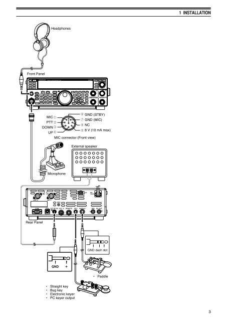
1 INSTALLATION UTILIZING THE BAIL This transceiver is equipped with a bail so that you can angle the transceiver. The bail is located on the bottom of the transceiver. Pull the bail forward to the limit as shown. REPLACING FUSES The following fuses are used in the <strong>TS</strong>-<strong>590S</strong> transceiver. If a fuse blows, determine the cause then correct the problem. Only after the problem has been resolved, replace the blown fuse with a new one with the specified ratings. If newly installed fuses continue to blow, disconnect the power plug and contact a <strong>Kenwood</strong> service center or your dealer for assistance. 2 Fuse Location Fuse Current Rating 4 A <strong>TS</strong>-<strong>590S</strong> Transceiver (for external antenna tuner) Supplied DC power cable 25 A Fuse (4 A) Fuse (25 A) Fuse (25 A) ACCESSORY CONNECTIONS FRONT PANEL ■ Headphones (PHONES) Connect monaural or stereo headphones with a 4 to 32 Ω (normal 8 Ω) impedance. This jack accepts a 6.3 mm (1/4") diameter, 2-conductor (mono) or 3-conductor (stereo) plug. After connecting the headphones, you will hear no sound from the internal (or optional external) Speaker/Microphone (MIC). Note: Using a high impedance headphone set causes the volume to be louder. ■ Microphone (MIC) Connect a microphone with a 250 to 600 Ω impedance. Fully insert the connector, then screw the retaining ring clockwise until secure. Compatible microphones include the MC-43S, MC-47, MC-52DM, MC-60A, MC-80, MC-85, and MC-90. Note: Do not use the MC-44, MC-44DM, MC-45, MC-45E, MC-45DM, MC-45DME, or MC-53DM microphones. REAR PANEL ■ External Speaker (EXT.SP) On the rear panel of the transceiver, there is an external speaker jack. If an external speaker is connected to EXP.SP, the transceiver internal speaker will mute. Use only external speakers with an impedance of 4 to 8 Ω (8 Ω nominal). This jack accepts only 3.5 mm (1/8") diameter, 2-conductor (mono) plugs. Do not connect headphones to this jack. The high audio output of this jack could damage your hearing. ■ Keys for CW (PADDLE and KEY) For CW operation while using the internal electronic keyer, connect a keyer paddle to the PADDLE jack. For CW operation without using the internal electronic keyer, connect a straight key, semi-automatic key (bug), electronic keyer, or the CW keyed output from a Multimode Communications Processor (MCP) to the KEY jack. The PADDLE and KEY jacks mate with a 6.3 mm (1/4") 3-conductor plug and a 3.5 mm (1/8") 2-conductor plug, respectively. External electronic keyers or MCPs must use positive keying to be compatible with this transceiver. Use a shielded cable between the key and the transceiver. Note: Due to the functionality of the internal electronic keyer, you may find it unnecessary to connect both a paddle and another type of keyer unless you want to use a PC-based keyer for CW. Read the “ELECTRONIC KEYER” section {page 33} to become familiar with the internal keyer.
Front Panel Rear Panel MIC PTT DOWN UP Headphones MIC connector (Front view) Microphone • Straight key • Bug key • Electronic keyer • PC keyer output GND (STBY) GND (MIC) NC 8 V (10 mA max) External speaker • Paddle 1 INSTALLATION 3