TS-590S - Kenwood
TS-590S - Kenwood
TS-590S - Kenwood

You also want an ePaper? Increase the reach of your titles
YUMPU automatically turns print PDFs into web optimized ePapers that Google loves.
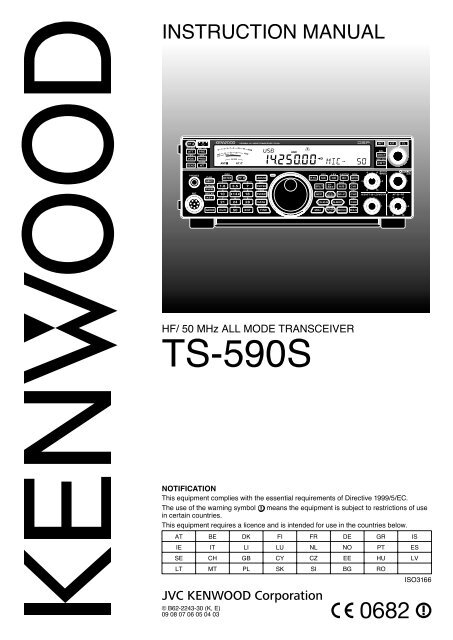
INSTRUCTION MANUAL<br />
HF/ 50 MHz ALL MODE TRANSCEIVER<br />
<strong>TS</strong>-<strong>590S</strong><br />
NOTIFICATION<br />
This equipment complies with the essential requirements of Directive 1999/5/EC.<br />
The use of the warning symbol means the equipment is subject to restrictions of use<br />
in certain countries.<br />
This equipment requires a licence and is intended for use in the countries below.<br />
AT BE DK FI FR DE GR IS<br />
IE IT LI LU NL NO PT ES<br />
SE CH GB CY CZ EE HU LV<br />
LT MT PL SK SI BG RO<br />
ISO3166<br />
© B62-2243-30 (K, E)<br />
09 08 07 06 05 04 03
THANK YOU<br />
Thank you for choosing this <strong>Kenwood</strong> <strong>TS</strong>-<strong>590S</strong><br />
transceiver. It has been developed by a team of<br />
engineers determined to continue the tradition of<br />
excellence and innovation in <strong>Kenwood</strong> transceivers.<br />
This transceiver features a Digital Signal Processing<br />
(DSP) unit to process IF and AF signals. By taking<br />
maximum advantage of DSP technology, the <strong>TS</strong>-<strong>590S</strong><br />
transceiver gives you enhanced interference reduction<br />
capabilities and improves the quality of audio. You will<br />
notice the differences when you fight QRM and QRN.<br />
As you learn how to use this transceiver, you will also<br />
find that <strong>Kenwood</strong> is pursuing “user friendliness”.<br />
For example, each time you change the Menu No. in<br />
Menu mode, you will see scrolling messages on the<br />
display, telling you what you are selecting.<br />
Though user friendly, this transceiver is technically<br />
sophisticated and some features may be new to you.<br />
Consider this manual to be a personal tutorial from the<br />
designers. Allow the manual to guide you through the<br />
learning process now, then act as a reference in the<br />
coming years.<br />
FEATURES<br />
• All mode operation from HF to 50 MHz amateur<br />
radio band<br />
• 500 Hz/ 2.7 kHz roofing filter<br />
• Superior C/N response by the DDS largely<br />
decreases the noise of the undesired signal.<br />
• IF DSP through the adoption of 32-bit floating point<br />
DSP<br />
• Digital Noise Blanker<br />
• PC interface via a Universal Serial Bus port<br />
(B-type)<br />
• Drive output and RX only antenna connector<br />
• Direct band keys<br />
• Built-in Antenna Tuner for the HF/ 50 MHz band<br />
• 100 W output power for SSB, CW, FSK, FM, and<br />
25 W output power for AM.<br />
Firmware Copyrights<br />
The title to and ownership of copyrights for firmware embedded<br />
in <strong>Kenwood</strong> product memories are reserved for JVC KENWOOD<br />
Corporation.<br />
NOTICE TO THE USER<br />
One or more of the following statements may be<br />
applicable for this equipment.<br />
FCC WARNING<br />
This equipment generates or uses radio frequency energy.<br />
Changes or modifications to this equipment may cause harmful<br />
interference unless the modifications are expressly approved<br />
in the instruction manual. The user could lose the authority to<br />
operate this equipment if an unauthorized change or modification<br />
is made.<br />
INFORMATION TO THE DIGITAL DEVICE USER REQUIRED<br />
BY THE FCC<br />
This equipment has been tested and found to comply with the<br />
limits for a Class B digital device, pursuant to Part 15 of the<br />
FCC Rules. These limits are designed to provide reasonable<br />
protection against harmful interference in a residential<br />
installation.<br />
This equipment generates, uses and can generate radio<br />
frequency energy and, if not installed and used in accordance<br />
with the instructions, may cause harmful interference to radio<br />
communications. However, there is no guarantee that the<br />
interference will not occur in a particular installation. If this<br />
equipment does cause harmful interference to radio or television<br />
reception, which can be determined by turning the equipment off<br />
and on, the user is encouraged to try to correct the interference<br />
by one or more of the following measures:<br />
• Reorient or relocate the receiving antenna.<br />
• Increase the separation between the equipment and<br />
receiver.<br />
• Connect the equipment to an outlet on a circuit different from<br />
that to which the receiver is connected.<br />
• Consult the dealer for technical assistance.<br />
BEFORE STARTING<br />
Amateur radio regulations vary from country to<br />
country. Confirm your local amateur radio regulations<br />
and requirements before operating the transceiver.<br />
Depending on the size and type of vehicle, the<br />
maximum transmission output power for the mobile<br />
operation will vary. The maximum transmission output<br />
power is usually specified by the car manufacturer<br />
to avoid interference with other electric devices used<br />
in the vehicle. Consult your car manufacturer and<br />
amateur radio equipment dealer for the requirements<br />
and installation.<br />
MARKET CODES<br />
K-type: The Americas<br />
E-type: Europe<br />
The market code is shown on the carton box.<br />
Refer to the specifications {page 81} for information<br />
on the available operating frequencies.<br />
Information on Disposal of Old Electrical and Electronic Equipment<br />
and Batteries (applicable for EU countries that have adopted<br />
separate waste collection systems)<br />
Products and batteries with the symbol (crossed-out wheeled<br />
bin) cannot be disposed as household waste.<br />
Old electrical and electronic equipment and batteries should<br />
be recycled at a facility capable of handling these items and<br />
their waste byproducts.<br />
Contact your local authority for details in locating a recycle<br />
facility nearest to you.<br />
Proper recycling and waste disposal will help conserve<br />
resources whilst preventing detrimental effects on our health<br />
and the environment.<br />
i
WRITING CONVENTIONS FOLLOWED<br />
The writing conventions described below have<br />
been followed to simplify instructions and avoid<br />
unnecessary repetition.<br />
ii<br />
Instruction Action<br />
Press [KEY]. Press and release KEY.<br />
Press Mic [KEY].<br />
Press and hold [KEY].<br />
Hold [KEY].<br />
Press [KEY] + [ ].<br />
Press and release KEY on<br />
the microphone.<br />
Press and hold KEY down<br />
for a moment, then release<br />
KEY.<br />
Press and hold KEY down<br />
until instructed to release<br />
KEY.<br />
With the transceiver power<br />
OFF, press and hold KEY,<br />
then switch the transceiver<br />
power ON by pressing [ ].<br />
SUPPLIED ACCESSORIES<br />
After carefully unpacking the transceiver, identify the<br />
items listed in the table below. We recommend you<br />
keep the box and packing materials in case you need<br />
to repack the transceiver in the future.<br />
Accessory Comment<br />
Quantity<br />
K-type E-type<br />
Microphone 1 1<br />
DC power cable 1 1<br />
Line filter (with<br />
retaining band)<br />
– 1<br />
Fuse<br />
25 A; for DC<br />
power cable<br />
4 A; for an<br />
1 1<br />
Fuse<br />
external<br />
antenna tuner<br />
1 1<br />
DIN plug 7-pin 1 1<br />
DIN plug 13-pin 1 1<br />
Screw set For bracket 1 1<br />
Plastic spacer For bracket 4 4<br />
English 1 1<br />
French 1 1<br />
Instruction Manual<br />
Spanish<br />
German<br />
–<br />
–<br />
1<br />
1<br />
Italian – 1<br />
Dutch – 1<br />
Schematic<br />
diagram<br />
2 –<br />
Warranty Card 1 1
PRECAUTIONS<br />
Please observe the following precautions to prevent<br />
fire, personal injury, and transceiver damage:<br />
• Connect the transceiver only to a power source<br />
as described in this manual or as marked on the<br />
transceiver itself.<br />
• Route all power cables safely. Ensure the power<br />
cables can neither be stepped upon nor pinched<br />
by items placed near or against the cables.<br />
Pay particular attention to locations near AC<br />
receptacles, AC outlet strips, and points of entry to<br />
the transceiver.<br />
• Take care not to drop objects or spill liquid into the<br />
transceiver through enclosure openings. Metal<br />
objects, such as hairpins or needles, inserted into<br />
the transceiver may contact voltages resulting in<br />
serious electrical shocks. Never permit children to<br />
insert any objects into the transceiver.<br />
• Do not attempt to defeat methods used for<br />
grounding and electrical polarization in the<br />
transceiver, particularly involving the power input<br />
cable.<br />
• Adequately ground all outdoor antennas for this<br />
transceiver using approved methods. Grounding<br />
helps protect against voltage surges caused by<br />
lightning. It also reduces the chance of a build-up<br />
of static charge.<br />
ELECTRIC SERVICE<br />
EQUIPMENT<br />
EXAMPLE OF ANTENNA GROUNDING<br />
GROUND<br />
CLAMP<br />
ANTENNA<br />
LEAD IN<br />
WIRE<br />
ANTENNA<br />
DISCHARGE UNIT<br />
GROUNDING<br />
CONDUCTORS<br />
GROUND CLAMPS<br />
POWER SERVICE<br />
GROUNDING ELECTRODE<br />
SYSTEM<br />
• Minimum recommended distance for an outdoor<br />
antenna from power lines is one and one-half<br />
times the vertical height of the associated antenna<br />
support structure. This distance allows adequate<br />
clearance from the power lines if the support<br />
structure fails for any reason.<br />
• Locate the transceiver so as not to interfere with its<br />
ventilation. Do not place books or other equipment<br />
on the transceiver that may impede the free<br />
movement of air. Allow a minimum of 10 cm<br />
(4 inches) between the rear of the transceiver and<br />
the wall or operating desk shelf.<br />
• Do not use the transceiver near water or sources<br />
of moisture. For example, avoid use near a<br />
bathtub, sink, swimming pool, or in a damp<br />
basement or attic.<br />
• The presence of an unusual odor or smoke is often<br />
a sign of trouble. Immediately turn the power OFF<br />
and remove the power cable. Contact a <strong>Kenwood</strong><br />
service station or your dealer for advice.<br />
• Locate the transceiver away from heat sources<br />
such as a radiator, stove, amplifier or other devices<br />
that produce substantial amounts of heat.<br />
• Do not use volatile solvents such as alcohol, paint<br />
thinner, gasoline, or benzene to clean the cabinet<br />
of the transceiver. Use only a clean cloth with<br />
warm water or a mild detergent.<br />
• Disconnect the input power cable from the power<br />
source when the transceiver is not used for long<br />
periods of time.<br />
• Remove the transceiver’s enclosure only to do<br />
accessory installations described in this manual or<br />
accessory manuals. Follow provided instructions<br />
carefully, to avoid electrical shocks. If unfamiliar<br />
with this type of work, seek assistance from an<br />
experienced individual, or have a professional<br />
technician do the task.<br />
• Enlist the services of qualified personnel in the<br />
following cases:<br />
a) The power supply or plug is damaged.<br />
b) Objects have fallen into or liquid has spilled into<br />
the transceiver.<br />
c) The transceiver has been exposed to rain.<br />
d) The transceiver is operating abnormally or<br />
performance has seriously degraded.<br />
e) The transceiver has been dropped or the<br />
enclosure damaged.<br />
• Do not attempt to perform any kind of configuration<br />
or menu setup while driving.<br />
• Do not wear headphones while driving.<br />
• Install the transceiver in a safe and convenient<br />
position inside your vehicle so as not to subject<br />
yourself to danger while driving. Consult your car<br />
dealer for the transceiver installation to ensure<br />
safety.<br />
• HF/ 50 MHz mobile antennas are larger and<br />
heavier than VHF/ UHF antennas. Therefore, use<br />
a strong and rigid mount to safely and securely<br />
install the HF/ 50 MHz mobile antenna.<br />
iii
CONTEN<strong>TS</strong><br />
iv<br />
THANK YOU ............................................................ i<br />
FEATURES .............................................................. i<br />
NOTICE TO THE USER ........................................... i<br />
BEFORE STARTING ............................................... i<br />
MARKET CODES ..................................................... i<br />
WRITING CONVENTIONS FOLLOWED .................ii<br />
SUPPLIED ACCESSORIES .....................................ii<br />
PRECAUTIONS ......................................................iii<br />
CONTEN<strong>TS</strong> .............................................................iv<br />
CHAPTER 1 INSTALLATION<br />
ANTENNA CONNECTION ...................................... 1<br />
GROUND CONNECTION ....................................... 1<br />
LIGHTNING PROTECTION .................................... 1<br />
DC POWER SUPPLY CONNECTION .................... 1<br />
UTILIZING THE BAIL .............................................. 2<br />
REPLACING FUSES .............................................. 2<br />
ACCESSORY CONNECTIONS .............................. 2<br />
FRONT PANEL ................................................... 2<br />
Headphones (PHONES) ................................ 2<br />
Microphone (MIC)........................................... 2<br />
REAR PANEL ...................................................... 2<br />
External Speaker (EXT.SP)............................ 2<br />
Keys for CW (PADDLE and KEY) .................. 2<br />
CHAPTER 2 GETTING ACQUAINTED<br />
FRONT PANEL ....................................................... 4<br />
LCD DISPLAY ......................................................... 7<br />
REAR PANEL .......................................................... 9<br />
MICROPHONE ........................................................ 9<br />
CHAPTER 3 OPERATING BASICS<br />
SWITCHING POWER ON/ OFF ............................ 10<br />
ADJUSTING THE VOLUME .................................. 10<br />
AF (AUDIO FREQUENCY) GAIN ...................... 10<br />
RF (RADIO FREQUENCY) GAIN ..................... 10<br />
SELECTING VFO A OR VFO B ............................ 10<br />
SELECTING A BAND ............................................ 11<br />
SELECTING A MODE ........................................... 11<br />
ADJUSTING THE SQUELCH................................ 12<br />
TUNING A FREQUENCY ...................................... 12<br />
MULTI-FUNCTION METER .................................. 12<br />
TRANSMITTING ................................................... 13<br />
SELECTING TRANSMISSION POWER ........... 13<br />
MICROPHONE GAIN ........................................ 13<br />
CHAPTER 4 MENU SETUP<br />
WHAT IS A MENU? .............................................. 14<br />
MENU A/ MENU B ................................................ 14<br />
MENU ACCESS .................................................... 14<br />
QUICK MENU ....................................................... 14<br />
PROGRAMMING THE QUICK MENU .............. 14<br />
USING THE QUICK MENU ............................... 14<br />
MENU CONFIGURATION ..................................... 15<br />
CHARACTER ENTRY ........................................... 20<br />
CHAPTER 5 BASIC COMMUNICATIONS<br />
SSB TRANSMISSION ........................................... 21<br />
FM TRANSMISSION ............................................. 21<br />
AM TRANSMISSION ............................................. 22<br />
NARROW BANDWIDTH FOR FM......................... 22<br />
CW TRANSMISSION ............................................ 22<br />
AUTO ZERO-BEAT ........................................... 23<br />
TX SIDETONE/ RX PITCH FREQUENCY ........ 23<br />
CARRIER LEVEL .................................................. 23<br />
POWER ON MESSAGE ........................................ 23<br />
CHAPTER 6 ENHANCED COMMUNICATIONS<br />
SPLIT-FREQUENCY OPERATION....................... 24<br />
TF-SET (TRANSMISSION FREQUENCY SET) 24<br />
FM REPEATER OPERATION ............................... 25<br />
TRANSMITTING A TONE ................................. 25<br />
Activating the Tone Function ........................ 26<br />
Selecting a Tone Frequency ........................ 26<br />
TONE FREQUENCY ID SCAN ......................... 26<br />
FM CTCSS OPERATION ...................................... 26<br />
CTCSS FREQUENCY ID SCAN ....................... 27<br />
CROSS TONE ....................................................... 27<br />
CHAPTER 7 COMMUNICATING AIDS<br />
RECEPTION ......................................................... 28<br />
SELECTING YOUR FREQUENCY ................... 28<br />
Direct Frequency Entry................................. 28<br />
Frequency Entry History ............................... 28<br />
Using the MHz key ....................................... 28<br />
Quick QSY.................................................... 28<br />
Fine Tuning .................................................. 29<br />
Tuning Control Adjustment Rate .................. 29<br />
Equalizing VFO Frequencies (A=B) ............. 29<br />
RIT (RECEIVE INCREMENTAL TUNING) ............ 29<br />
AGC (AUTOMATIC GAIN CONTROL) .............. 29<br />
AGC Time Constant Adjustment .................. 29<br />
TRANSMISSION ................................................... 30<br />
VOX (VOICE-OPERATED TRANSMISSION) ... 30<br />
Microphone Input Level ................................ 30<br />
Delay Time ................................................... 30<br />
Anti-VOX Adjustment ................................... 30<br />
Data VOX ..................................................... 30<br />
Data VOX Delay Time .................................. 31<br />
USB/ ACC2 VOX Gain ................................. 31<br />
SPEECH PROCESSOR .................................... 31<br />
peech Processor Effect ................................ 31<br />
XIT (TRANSMIT INCREMENTAL TUNING) ..... 31<br />
CUSTOMIZING TRANSMISSION SIGNAL<br />
CHARACTERISTICS ........................................ 32<br />
TX Filter Bandwidth (SSB/ AM) .................... 32<br />
TX Filter Bandwidth (LSB-DATA/ USB-DATA) .32<br />
TX Equalizer (SSB/ AM/ FM)........................ 32<br />
TRANSMIT INHIBIT .......................................... 32<br />
BUSY LOCKOUT .............................................. 32<br />
CHANGING FREQUENCY WHILE<br />
TRANSMITTING ............................................... 32<br />
CW BREAK-IN ...................................................... 33<br />
USING SEMI BREAK-IN OR FULL BREAK-IN ..... 33<br />
ELECTRONIC KEYER .......................................... 33<br />
ELECTRONIC KEYER MODE .......................... 33<br />
CHANGING KEYING SPEED ........................... 33<br />
Invalid Break-In Operation............................ 33<br />
RISE TIME OF CW ........................................... 34<br />
AUTO WEIGHTING ........................................... 34<br />
Reverse Keying Weight Ratio ...................... 34<br />
BUG KEY FUNCTION ....................................... 34<br />
CW MESSAGE MEMORY ................................ 34<br />
Storing CW Messages.................................. 34<br />
Checking CW Messages without<br />
Transmitting.................................................. 35
Transmitting CW Messages ......................... 35<br />
Changing the Inter-message Interval Time ... 35<br />
Changing the CW Sidetone Volume............. 35<br />
Insert Keying ................................................ 35<br />
FREQUENCY CORRECTION FOR CW ........... 35<br />
AUTO CW TX IN SSB MODE ........................... 36<br />
MIC UP/ DWN KEY PADDLE MODE ................ 36<br />
SWAP DOT AND DASH PADDLE POSITIONS 36<br />
CHAPTER 8 DATA COMMUNICATIONS<br />
RADIO TELETYPE (RTTY) ................................... 37<br />
PHASE-SHIFT KEYING 31 BAUD (PSK31).......... 37<br />
CHAPTER 9 REJECTING INTERFERENCE<br />
DSP FILTERS ....................................................... 38<br />
CHANGING THE DSP FILTER BANDWIDTH .. 38<br />
SSB/ FM/ AM Mode...................................... 38<br />
CW/ FSK Mode ............................................ 38<br />
Data Mode .................................................... 38<br />
IF Filter A and B ........................................... 38<br />
AUTO NOTCH FILTER (SSB) ............................... 39<br />
AUTO NOTCH TRACKING SPEED .................. 39<br />
MANUAL NOTCH FILTER (SSB/ CW/ FSK) ......... 39<br />
Notch Filter Bandwidth ................................. 39<br />
BEAT CANCEL (SSB/ AM) ............................... 39<br />
NOISE REDUCTION (ALL MODES) ................. 39<br />
Setting the NR1 Level Adjustment ............... 40<br />
Setting the NR2 Time Constant.................... 40<br />
NOISE BLANKER ................................................. 40<br />
PRE-AMPLIFIER ................................................... 40<br />
ATTENUATOR ...................................................... 40<br />
CW REVERSE (RECEPTION) .............................. 40<br />
CHAPTER 10 MEMORY FEATURES<br />
MEMORY CHANNELS .......................................... 41<br />
STORING DATA IN MEMORY .......................... 41<br />
Simplex Channels ........................................ 41<br />
Split-Frequency Channels ............................ 41<br />
MEMORY RECALL AND SCROLL ................... 42<br />
Memory Recall ............................................. 42<br />
Memory Scroll .............................................. 42<br />
Temporary Frequency Changes................... 42<br />
MEMORY TRANSFER ...................................... 42<br />
Memory ➡ VFO Transfer .............................. 42<br />
Channel ➡ Channel Transfer ....................... 42<br />
STORING FREQUENCY RANGES .................. 43<br />
Confirming Start/ End Frequencies .............. 44<br />
Programmable VFO ..................................... 44<br />
MEMORY CHANNEL LOCKOUT ...................... 44<br />
ERASING MEMORY CHANNELS .................... 44<br />
MEMORY CHANNEL NAME ............................. 44<br />
QUICK MEMORY .................................................. 44<br />
NUMBER OF QUICK MEMORY CHANNELS ... 45<br />
STORING INTO QUICK MEMORY ................... 45<br />
RECALLING QUICK MEMORY CHANNELS .... 45<br />
TEMPORARY FREQUENCY CHANGES ......... 45<br />
QUICK MEMORY ➡ VFO TRANSFER ............. 45<br />
ERASING QUICK MEMORY CHANNELS ........ 45<br />
CHAPTER 11 SCAN<br />
NORMAL SCAN .................................................... 46<br />
VFO SCAN ........................................................ 46<br />
PROGRAM SCAN ............................................. 46<br />
CONTEN<strong>TS</strong><br />
PROGRAM SCAN PARTIALLY SLOWED ........ 47<br />
SCAN HOLD ..................................................... 48<br />
MEMORY SCAN ................................................... 48<br />
SCAN RESUME ................................................ 48<br />
ALL-CHANNEL SCAN ....................................... 48<br />
GROUP SCAN .................................................. 49<br />
Memory Group ............................................. 49<br />
Scan Group Select ....................................... 49<br />
Performing Group Scan................................ 49<br />
QUICK MEMORY SCAN ....................................... 49<br />
CHAPTER 12 OPERATOR CONVENIENCES<br />
ANTENNAS ........................................................... 50<br />
ANT 1/ ANT 2 .................................................... 50<br />
RX ANT ............................................................. 50<br />
DRV ................................................................... 50<br />
APO (Auto Power OFF) ......................................... 50<br />
AUTOMATIC ANTENNA TUNER .......................... 50<br />
PRESETTING ................................................... 51<br />
AUTO MODE ......................................................... 51<br />
BEEP FUNCTION ................................................. 52<br />
DISPLAY ............................................................... 53<br />
BRIGHTNESS ................................................... 53<br />
BACKLIGHT COLOR ........................................ 53<br />
PANEL KEY DOUBLE FUNCTION RESPONSE<br />
TIME ...................................................................... 53<br />
LINEAR AMPLIFIER CONTROL ........................... 53<br />
LOCK FUNCTIONS ............................................... 53<br />
FREQUENCY LOCK FUNCTION ..................... 53<br />
PROGRAMMABLE FUNCTION KEYS.................. 54<br />
TRANSCEIVER FRONT PANEL ....................... 54<br />
MICROPHONE KEYS ....................................... 54<br />
DSP RX EQUALIZER ............................................ 55<br />
Equalizing Receiving Audio .......................... 55<br />
RX MONITOR ................................................... 55<br />
TIME-OUT TIMER ................................................. 55<br />
TRANSVERTER .................................................... 55<br />
FREQUENCY DISPLAY .................................... 55<br />
TRANSMISSION OUTPUT POWER ................. 56<br />
TX MONITOR ........................................................ 56<br />
TX POWER ........................................................... 56<br />
TX TUNE ............................................................... 56<br />
QUICK DATA TRANSFER .................................... 56<br />
SETTING UP ..................................................... 56<br />
Equipment Needed....................................... 56<br />
Connections ................................................. 56<br />
USING QUICK TRANSFER .............................. 57<br />
Transferring Data ......................................... 57<br />
Receiving Data ............................................. 57<br />
COMPUTER CONTROL ....................................... 57<br />
SETTING UP ..................................................... 57<br />
Equipment Needed....................................... 57<br />
Connections ................................................. 57<br />
COMMUNICATION PARAMETERS ................. 57<br />
EXTERNAL AUDIO SETTINGS ........................ 58<br />
Selecting a Data Transmission Line ............. 58<br />
Audio Level Settings..................................... 58<br />
TERMINAL ........................................................ 58<br />
CONTROLLING THE <strong>TS</strong>-<strong>590S</strong> FROM A PC .... 58<br />
REMOTELY CONTROLLING THE <strong>TS</strong>-<strong>590S</strong> ON<br />
THE NETWORK ................................................ 58<br />
OPTIONAL VGS-1 VOICE GUIDE & STORAGE<br />
UNIT ...................................................................... 58<br />
v
CONTEN<strong>TS</strong><br />
vi<br />
RECORDING MESSAGES ............................... 58<br />
MESSAGE PLAYBACK ..................................... 59<br />
Checking Messages ..................................... 59<br />
Sending Messages ....................................... 59<br />
Erasing a Recorded Message ...................... 59<br />
Changing Inter-message Interval Time ........ 59<br />
Changing Message Playback Volume.......... 60<br />
CONSTANT RECORDING ................................ 60<br />
VOICE GUIDE ................................................... 60<br />
Voice Guide Announcement Volume .......... 62<br />
Voice Guide Announcement Speed ............ 62<br />
Voice Guide Announcement Language ....... 62<br />
EMERGENCY CALL (K TYPE ONLY) .................. 62<br />
CROSSBAND REPEATER .................................. 63<br />
OPERATION ..................................................... 63<br />
DX PACKETCLUSTER TUNE............................... 63<br />
SKY COMMAND SYSTEM II................................. 64<br />
SKY COMMAND SYSTEM II DIAGRAM ........... 64<br />
PREPARATION ................................................. 64<br />
CHAPTER 13 CONNECTING PERIPHERAL EQUIPMENT<br />
TERMINAL DESCRIPTIONS ................................ 65<br />
COM CONNECTOR .......................................... 65<br />
ACC2 CONNECTOR ......................................... 65<br />
REMOTE CONNECTOR ................................... 66<br />
EXT.AT CONNECTOR (FOR AT-300) .............. 66<br />
MIC CONNECTOR ............................................ 66<br />
COMPUTER .......................................................... 67<br />
COMPATIBLE TRANSCEIVER ............................. 67<br />
RTTY OPERATION ............................................... 68<br />
HF/ 50 MHz LINEAR AMPLIFIER ......................... 68<br />
ANTENNA TUNER ................................................ 69<br />
TNC AND MCP ..................................................... 69<br />
DX PACKETCLUSTER TUNE............................... 70<br />
CROSSBAND REPEATER ................................... 70<br />
CHAPTER 14 INSTALLING OPTIONS<br />
REMOVING THE BOTTOM CASE........................ 71<br />
VGS-1 VOICE GUIDE & STORAGE UNIT ............ 71<br />
SO-3 TCXO ........................................................... 72<br />
REFERENCE FREQUENCY CALIBRATION ....... 72<br />
MB-430 MOBILE BRACKET ................................. 73<br />
PRECAUTIONS ................................................ 73<br />
CHAPTER 15 TROUBLESHOOTING<br />
GENERAL INFORMATION ................................... 74<br />
SERVICE ........................................................... 74<br />
SERVICE NOTE ................................................ 74<br />
CLEANING ........................................................ 74<br />
TROUBLESHOOTING .......................................... 75<br />
MICROPROCESSOR RESET............................... 78<br />
INITIAL SETTINGS ........................................... 78<br />
VFO RESET ...................................................... 78<br />
FULL RESET ..................................................... 78<br />
OPERATION NOTICES ........................................ 79<br />
DC POWER SUPPLY ....................................... 79<br />
INTERNAL COOLING FAN ............................... 79<br />
INTERNAL BEA<strong>TS</strong> ............................................ 79<br />
AGC ................................................................... 79<br />
60m BAND OPERATION (K-TYPE/ USA ONLY) ..79<br />
CHAPTER 16 OPTIONAL ACCESSORIES<br />
OPTIONAL ACCESSORIES ................................. 80<br />
CHAPTER 17 SPECIFICATIONS<br />
SPECIFICATIONS ................................................ 81
INSTALLATION<br />
ANTENNA CONNECTION<br />
An antenna system consists of an antenna, feed<br />
line, and ground. The transceiver can give excellent<br />
results if the antenna system and its installation are<br />
given careful attention. Use a properly adjusted 50 Ω<br />
antenna of good quality, a high-quality 50 Ω coaxial<br />
cable, and top-quality connectors. All connections<br />
must be clean and tight.<br />
After making the connections, match the impedance<br />
of the coaxial cable and antenna so that the SWR is<br />
1.5:1 or less. High SWR will cause the transmit output<br />
to drop and may lead to radio frequency interference<br />
with consumer products such as stereo receivers<br />
and televisions. You may even cause interference<br />
with your own transceiver. Reports that your signal is<br />
distorted could indicate that your antenna system is<br />
not efficiently radiating your transceiver’s power.<br />
Connect your primary HF/ 50 MHz antenna feed<br />
line to ANT 1 on the rear of the transceiver. If you<br />
are using two HF/ 50 MHz antennas, connect the<br />
secondary antenna to ANT 2. Refer to page 9 for the<br />
location of the antenna connectors.<br />
The LF band is outputed only from the DRV terminal.<br />
Note:<br />
◆ Transmitting without connecting an antenna or other<br />
matched load may damage the transceiver. Always connect<br />
the antenna to the transceiver before transmitting.<br />
◆ All fixed stations should be equipped with a lightning arrester<br />
to reduce the risk of fire, electric shock, and transceiver<br />
damage.<br />
◆ The transceiver’s protection circuit will activate when<br />
the SWR is greater than 1.5:1; however, do not rely on<br />
protection to compensate for a poorly functioning antenna<br />
system.<br />
GROUND CONNECTION<br />
At a minimum, a good DC ground is required to<br />
prevent such dangers as electric shock. For superior<br />
communications, a good RF ground is required<br />
against which the antenna system can operate. Both<br />
of these conditions can be met by providing a good<br />
earth ground for your station. Bury one or more<br />
ground rods or a large copper plate under the ground,<br />
then connect this to the transceiver GND terminal.<br />
Use heavy gauge wire or a copper strap, cut as short<br />
as possible, for this connection. Do not use a gas<br />
pipe, an electrical conduit, or a plastic water pipe as a<br />
ground.<br />
<strong>TS</strong>-<strong>590S</strong><br />
LIGHTNING PROTECTION<br />
Even in areas where lightning storms are less<br />
common, there is always a chance that a storm will<br />
occur each year. Consider carefully how to protect<br />
your equipment and home from lightning. The<br />
installation of a lightning arrestor is a start, but there<br />
is more that you can do. For example, terminate<br />
your antenna system transmission lines at an entry<br />
panel that you install outside your home. Ground this<br />
entry panel to a good outside ground, then connect<br />
the appropriate feed lines between the entry panel<br />
and your transceiver. When a lightning storm occurs,<br />
disconnecting the feed lines from your transceiver will<br />
ensure additional protection.<br />
DC POWER SUPPLY CONNECTION<br />
In order to use this transceiver, you need a separate<br />
13.8 V DC power supply that must be purchased<br />
separately. Do not directly connect the transceiver<br />
to an AC outlet. Use the supplied DC power cable to<br />
connect the transceiver to a regulated power supply.<br />
Do not substitute a cable with smaller gauge wires.<br />
The current capacity of the power supply must be<br />
20.5 A peak or more.<br />
First, connect the DC power cable to the regulated DC<br />
power supply; the red lead to the positive terminal and<br />
the black lead to the negative terminal. Next, connect<br />
the DC power cable to the transceiver’s DC power<br />
connector.<br />
• Press the connectors firmly until the locking tab<br />
clicks.<br />
• Attach the line filter to the DC cable as shown<br />
below (E-type only).<br />
Note:<br />
◆ Before connecting the DC power supply to the transceiver,<br />
be sure to switch OFF the DC power supply and transceiver.<br />
◆ Do not plug the DC power supply into an AC outlet until you<br />
make all connections.<br />
E-type only<br />
DC Power supply<br />
(20.5 A or more)<br />
Black (−)<br />
Fuse (25 A)<br />
Red (+)<br />
1
1 INSTALLATION<br />
UTILIZING THE BAIL<br />
This transceiver is equipped with a bail so that you<br />
can angle the transceiver. The bail is located on the<br />
bottom of the transceiver. Pull the bail forward to the<br />
limit as shown.<br />
REPLACING FUSES<br />
The following fuses are used in the <strong>TS</strong>-<strong>590S</strong><br />
transceiver. If a fuse blows, determine the cause<br />
then correct the problem. Only after the problem has<br />
been resolved, replace the blown fuse with a new<br />
one with the specified ratings. If newly installed fuses<br />
continue to blow, disconnect the power plug and<br />
contact a <strong>Kenwood</strong> service center or your dealer for<br />
assistance.<br />
2<br />
Fuse Location Fuse Current Rating<br />
4 A<br />
<strong>TS</strong>-<strong>590S</strong> Transceiver<br />
(for external<br />
antenna tuner)<br />
Supplied DC power cable 25 A<br />
Fuse (4 A)<br />
Fuse (25 A)<br />
Fuse (25 A)<br />
ACCESSORY CONNECTIONS<br />
FRONT PANEL<br />
■ Headphones (PHONES)<br />
Connect monaural or stereo headphones with a<br />
4 to 32 Ω (normal 8 Ω) impedance. This jack<br />
accepts a 6.3 mm (1/4") diameter, 2-conductor<br />
(mono) or 3-conductor (stereo) plug. After<br />
connecting the headphones, you will hear no<br />
sound from the internal (or optional external)<br />
Speaker/Microphone (MIC).<br />
Note: Using a high impedance headphone set causes the<br />
volume to be louder.<br />
■ Microphone (MIC)<br />
Connect a microphone with a 250 to 600 Ω<br />
impedance. Fully insert the connector, then<br />
screw the retaining ring clockwise until secure.<br />
Compatible microphones include the MC-43S,<br />
MC-47, MC-52DM, MC-60A, MC-80, MC-85, and<br />
MC-90.<br />
Note: Do not use the MC-44, MC-44DM, MC-45, MC-45E,<br />
MC-45DM, MC-45DME, or MC-53DM microphones.<br />
REAR PANEL<br />
■ External Speaker (EXT.SP)<br />
On the rear panel of the transceiver, there is an<br />
external speaker jack. If an external speaker is<br />
connected to EXP.SP, the transceiver internal<br />
speaker will mute. Use only external speakers with<br />
an impedance of 4 to 8 Ω (8 Ω nominal). This jack<br />
accepts only 3.5 mm (1/8") diameter, 2-conductor<br />
(mono) plugs.<br />
Do not connect headphones to this jack. The high audio<br />
output of this jack could damage your hearing.<br />
■ Keys for CW (PADDLE and KEY)<br />
For CW operation while using the internal<br />
electronic keyer, connect a keyer paddle to the<br />
PADDLE jack.<br />
For CW operation without using the internal<br />
electronic keyer, connect a straight key,<br />
semi-automatic key (bug), electronic keyer,<br />
or the CW keyed output from a Multimode<br />
Communications Processor (MCP) to the KEY<br />
jack.<br />
The PADDLE and KEY jacks mate with a 6.3 mm<br />
(1/4") 3-conductor plug and a 3.5 mm (1/8")<br />
2-conductor plug, respectively. External electronic<br />
keyers or MCPs must use positive keying to be<br />
compatible with this transceiver. Use a shielded<br />
cable between the key and the transceiver.<br />
Note: Due to the functionality of the internal electronic<br />
keyer, you may find it unnecessary to connect both a paddle<br />
and another type of keyer unless you want to use a<br />
PC-based keyer for CW. Read the “ELECTRONIC KEYER”<br />
section {page 33} to become familiar with the internal keyer.
Front Panel<br />
Rear Panel<br />
MIC <br />
PTT <br />
DOWN <br />
UP <br />
Headphones<br />
MIC connector (Front view)<br />
Microphone<br />
• Straight key<br />
• Bug key<br />
• Electronic keyer<br />
• PC keyer output<br />
GND (STBY)<br />
GND (MIC)<br />
NC<br />
8 V (10 mA max)<br />
External speaker<br />
• Paddle<br />
1 INSTALLATION<br />
3
GETTING ACQUAINTED<br />
FRONT PANEL<br />
4<br />
A<br />
B<br />
—— A ——<br />
[ ]<br />
Press and hold to switch the transceiver power ON<br />
and OFF {page 10}.<br />
[PF A]<br />
You can assign a function to this Programmable<br />
Function key {page 54}.<br />
[ATT (RX ANT)]<br />
Press to turn the receiver attenuator ON or OFF<br />
{page 40}. Press and hold to enable or disable the<br />
RX-ANT terminal {page 50}.<br />
[PRE (ANT 1/2)]<br />
Press to turn the pre-amplifier ON or OFF {page 40}.<br />
Press and hold to select either ANT 1 or ANT 2<br />
{page 50}.<br />
[VOX (LEV)]<br />
In voice mode, press to turn the VOX (Voice-Operated<br />
Transmit) function ON or OFF {page 30}. In CW<br />
mode, press to turn the Break-in function ON or OFF<br />
{page 33}. Press and hold to adjust the microphone<br />
input gain for VOX operation.<br />
[PROC (LEV)]<br />
Press to turn the Speech Processor ON or OFF<br />
{page 31}. Press and hold to adjust the Speech<br />
Processor input level.<br />
[SEND]<br />
Press to turn transmission ON or OFF.<br />
[AT (TUNE)]<br />
Press to turn the internal antenna tuner ON or<br />
OFF {page 50}. Press and hold to start tuning the<br />
automatic antenna tuner.<br />
—— B ——<br />
PHONES jack<br />
Mate with a 6.3 mm (1/4") diameter, 2-conductor<br />
(mono) or 3-conductor (stereo) plug for connecting a<br />
set of headphones {page 2}.<br />
MIC connector<br />
Connect a microphone to this connector {page 2}.<br />
C D E<br />
F<br />
—— C ——<br />
[METER (DRV)]<br />
Press to switch the meter type {page 12}. Press and<br />
hold to turn the Drive Out function ON or OFF {page 50}.<br />
[PF B]<br />
You can assign a function to this Programmable<br />
Function key {page 54}.<br />
[MIC (CAR)]<br />
Press to adjust the microphone gain {page 13}. While<br />
the Speech Processor function is ON, press to adjust<br />
the Speech Processor output level {page 31}. Press<br />
and hold to adjust the carrier level {page 23}.<br />
[PWR (TX MONI)]<br />
Press to adjust the transmission output power<br />
{pages 13, 565}. Press and hold to turn the<br />
transmission signal monitor function ON or OFF<br />
{page 56}.<br />
[KEY (DELAY)]<br />
Press to adjust the internal electronic keyer speed<br />
{page 33}. Press and hold to adjust the VOX delay<br />
time for voice mode {page 30} or Break-in time (Full<br />
Break-in/ Semi Break-in time) for CW mode.<br />
[GENE]<br />
Press to select the general coverage band memory<br />
{page 11}.<br />
[1.8 (1)]<br />
Press to select the 1.8 MHz band memory {page 11}<br />
or enter keypad number 1.<br />
[3.5 (2)]<br />
Press to select the 3.5 MHz band memory {page 11}<br />
or enter keypad number 2.<br />
[7 (3)]<br />
Press to select the 7 MHz band memory {page 11} or<br />
enter keypad number 3.<br />
[10 (4)]<br />
Press to select the 10 MHz band memory {page 11} or<br />
enter keypad number 4.<br />
[14 (5)]<br />
Press to select the 14 MHz band memory {page 11} or<br />
enter keypad number 5.<br />
[18 (6)]<br />
Press to select the 18 MHz band memory {page 11} or<br />
enter keypad number 6.<br />
G<br />
H
[21 (7)]<br />
Press to select the 21 MHz band memory {page 11} or<br />
enter keypad number 7.<br />
[24 (8)]<br />
Press to select the 24 MHz band memory {page 11} or<br />
enter keypad number 8.<br />
[28 (9)]<br />
Press to select the 28 MHz band memory {page 11} or<br />
enter keypad number 9.<br />
[50 (0)]<br />
Press to select the 50 MHz band memory {page 11} or<br />
enter keypad number 0.<br />
[CLR]<br />
Press to exit from, abort, or reset various functions.<br />
Press and hold to clear a memory channel {page 44}.<br />
[ENT]<br />
Press to enter your desired frequency using the<br />
10-key keypad {page 28}.<br />
—— D ——<br />
[LSB/USB]<br />
Press to select LSB or USB mode {page 11}.<br />
[CW/FSK (REV)]<br />
Press to select CW or FSK mode {page 11}. Press<br />
and hold to select a sideband (CW/ CW-R or FSK/<br />
FSK-R).<br />
[FM/AM (FM-N)]<br />
Press to select FM or AM mode {page 11}. Press and<br />
hold to select Narrow FM mode.<br />
[DATA]<br />
Press to select a Data mode (LSB/ LSB-DATA, USB/<br />
USB-DATA, or FM/ FM-DATA) {page 11}.<br />
[FINE (F.LOCK)]<br />
Press to activate the Fine tuning function to allow<br />
more precise tuning {page 29}. Press and hold to<br />
activate the Frequency Lock function {page 53}.<br />
—— E ——<br />
Central (Tuning) control<br />
Turn to select the desired frequency {page 12}. Use<br />
the convenient finger-tip cavity for continuous tuning.<br />
Slide the lever underneath the Tuning control to the<br />
left or right to adjust the torque level of the control.<br />
Left makes the control light and right makes it heavy.<br />
light<br />
heavy<br />
TX-RX LED<br />
Lights red while transmitting and green when the<br />
squelch opens while receiving.<br />
—— F ——<br />
[IF FIL]<br />
Press to toggle between IF Filter A and IF Filter B<br />
{page 38}. You can adjust the filter bandwidth using<br />
the LO/WIDTH and HI/SHIFT controls. Press and<br />
hold [IF FIL] to momentarily display each setting value<br />
of the current DSP filter DSP filter bandwidth {page<br />
38}.<br />
2 GETTING ACQUAINTED<br />
[NB (LEV)]<br />
Press to cycle through Noise Blanker 1, Noise Blanker<br />
2, and OFF. Press and hold to adjust the Noise<br />
Blanker level {page 40}.<br />
[NR (LEV)]<br />
Press to cycle through the DSP Noise Reduction<br />
types: NR1, NR2, or OFF {page 39}. When the<br />
Noise Reduction function is turned ON, press and<br />
hold to change the parameters of the Noise Reduction<br />
function {page 40}.<br />
[BC (A.NOTCH)]<br />
Press to select the DSP Beat Cancel function, BC1<br />
(Beat Cancel 1), BC2 (Beat Cancel 2) or OFF<br />
{page 39}. Press and hold to toggle the Auto<br />
Notch Filter ON and OFF {page 39}.<br />
[NOTCH (WIDE)]<br />
Press to toggle the IF Notch Filter ON or OFF<br />
{page 39}. Press and hold to set up the IF Notch<br />
bandwidth {page 39}.<br />
[SPLIT]<br />
Press to enter split-frequency operation, allowing<br />
you to use different transmission and reception<br />
frequencies {page 24}.<br />
[TF-SET]<br />
During split-frequency operation, press to monitor or<br />
change your transmit frequency {page 24}.<br />
[A/B (A=B)]<br />
Press to select either VFO A or VFO B {page 24}.<br />
Press and hold to duplicate the data in the current<br />
VFO to the other VFO {page 25}. While in Menu<br />
mode, press to select Menu A or Menu B. While in<br />
Program Memory Channel mode, press to recall the<br />
start or end frequency.<br />
[M/V]<br />
Press to toggle between Memory and VFO modes.<br />
[M.IN]<br />
Press to enter Memory Scroll mode and to store data<br />
to a Memory channel {page 41}.<br />
[M>V]<br />
Press to transfer the current Memory Channel<br />
contents to the VFO.<br />
[Q-M.IN]<br />
Press to store data to the Quick Memory {page 44}.<br />
[Q-MR]<br />
Press to recall data from the Quick Memory {page 45},<br />
while in VFO mode. Press to enter Memory Name<br />
Edit mode, while in Memory Channel mode {page 44}.<br />
[MHz]<br />
Press to turn the MHz Up/ Down function ON or OFF.<br />
The MHz digit increases or decreases when you turn<br />
the MULTI/CH control. In Menu mode, press to turn<br />
the Quick Menu ON or OFF {page 14}.<br />
[SCAN (SG.SEL)]<br />
Press to start or stop the Scan function {page 46}.<br />
Press and hold to select a Scan group {page 49}.<br />
[MENU]<br />
Press to enter Menu mode {page 14}.<br />
5
2 GETTING ACQUAINTED<br />
[CH1 (REC)]<br />
Press to play back a CW {page 34} or voice message<br />
(requires VGS-1 option) {page 58}. Press and hold<br />
to record a CW {page 34} or voice message (requires<br />
VGS-1 option) {page 59}.<br />
[CH2 (REC)]<br />
Press to play back a CW {page 34} or voice message<br />
(requires VGS-1 option) {page 59}. Press and hold<br />
to record a CW {page 34} or voice message (requires<br />
VGS-1 option) {page 59}.<br />
[CH3 (REC)]<br />
Press to play back a CW {page 34} or voice message<br />
(requires VGS-1 option) {page 59}. Press and hold<br />
to record a CW {page 34} or voice message (requires<br />
VGS-1 option) {page 59}.<br />
[RX/4 (REC)]<br />
Press to play back a CW {page 34} or voice message<br />
(requires VGS-1 option) {page 59}, or the constantly<br />
recorded signal (requires VGS-1 option) {page 60}.<br />
Press and hold to activate the constant recorder<br />
(requires VGS-1 option) {page 60}.<br />
6<br />
A<br />
B<br />
—— G ——<br />
[AGC/T (SEL)]<br />
Press to toggle the fast or slow response time for<br />
the Automatic Gain Control (AGC) {page 29}. In<br />
FM mode, press to cycle through the Tone settings:<br />
Tone, CTCSS, CTCSSx, or OFF {page 26}. When<br />
Tone is activated in FM mode, press and hold to<br />
select a Tone frequency {page 26}. When CTCSS<br />
is activated in FM mode, press and hold to select a<br />
CTCSS frequency {page 27}.<br />
[CW T. (AGC OFF)]<br />
Press to start CW auto tuning {page 23}. Press and<br />
hold to turn AGC OFF {page 29}.<br />
[RIT]<br />
Press to turn the RIT (Receive Incremental Tuning)<br />
function ON or OFF {page 29}.<br />
[XIT]<br />
Press to turn the XIT (Transmit Incremental Tuning)<br />
function ON or OFF {page 31}.<br />
[CL]<br />
Press to clear the RIT/ XIT frequency to zero<br />
{pages 29, 31}.<br />
C D E<br />
F<br />
RIT/ XIT control<br />
When the RIT/ XIT function is ON, turn to adjust<br />
the offset frequency. The RIT/ XIT offset frequency<br />
appears on the sub-display {pages 29, 31}. While<br />
scanning, turn to adjust the scan speed.<br />
—— H ——<br />
SQL control<br />
Turn to select the desired squelch level {page 12}.<br />
NOTCH control<br />
Turn to select the desired Notch frequency {page 39}.<br />
MULTI/CH control<br />
In VFO mode, rotate to step the operating frequency<br />
up or down {page 28}. In Memory Channel mode,<br />
rotate to select a Memory Channel {page 41}.<br />
Also, used for selecting Menu numbers when<br />
accessing the Menu mode {page 14} and for various<br />
configurations. The MULTI/CH LED lights when the<br />
MULTI/CH control is not being used to adjust the step<br />
frequency.<br />
HI/SHIFT control<br />
Rotate to adjust the DSP filter bandwidth (high-cut) or<br />
to adjust the DSP filter bandwidth (filter band shift)<br />
{page 38}.<br />
LO/WIDTH control<br />
Rotate to adjust the DSP filter bandwidth (high-cut or<br />
shift) {page 38}.<br />
AF control<br />
Turn to adjust the AF gain level {page 10}.<br />
RF control<br />
Turn to adjust the RF gain level {page 10}.<br />
G<br />
H
LCD DISPLAY<br />
A B C D<br />
E F<br />
—— A ——<br />
While receiving, the meter serves as an S-meter to<br />
measure and display the received signal strength.<br />
While transmitting, it serves as a power meter plus an<br />
ALC meter, an SWR meter, or a Speech Processor<br />
compression meter. The Peak Hold function holds<br />
each reading for approximately half a second. While<br />
adjusting the IF filter bandwidth, the meter displays an<br />
adjustment state.<br />
—— B ——<br />
Appears when the Auto Mode function is ON and<br />
while in Auto Mode frequency setup {page 51}.<br />
Displays the operating mode (USB, LSB, FM, AM,<br />
CW, CWR, FSK, or FSR) {page 11}.<br />
Appears while in Menu mode {page 14}.<br />
Appears while in Memory Scroll mode {page 42}.<br />
Appears while in Memory Channel mode or Memory<br />
Scroll mode {page 42}.<br />
In normal operating mode and various configuration<br />
modes, it displays the Memory Channel number,<br />
Quick Memory number, and entry log number. In<br />
Menu mode, it displays the Menu No.<br />
—— C ——<br />
Appears while in Data mode {page 38}.<br />
Appears while in narrow FM mode {page 11}.<br />
Appears when the receiver pre-amplifier is ON {page<br />
40}.<br />
Appears when the receiver’s attenuator is ON {page<br />
40}.<br />
2 GETTING ACQUAINTED<br />
Appears when the Noise Blanker 1 or 2 is ON<br />
{page 40}.<br />
“ ” (fast) or “ ” (slow) appears when the<br />
Automatic Gain Control function is ON. “ ”<br />
appears when the AGC is OFF {page 29}.<br />
Appears when IF filter A is selected {page 38}.<br />
Appears when IF filter B is selected {page 38}.<br />
—— D ——<br />
“ ” appears when manual notch is set to Normal.<br />
“ ” appears when Manual Notch is set to Wide.<br />
“ ” appears when Auto Notch is selected {page<br />
39}.<br />
Appears when the Fine Tuning function is ON {page<br />
29}.<br />
Appears when the MHz Step function is ON {page<br />
28}. Also appears when the Quick Menu function is<br />
ON {page 14}.<br />
“ ” or “ ” appears, depending on whether<br />
DSP Noise Reduction 1 or Noise Reduction 2 is<br />
selected {page 39}.<br />
“ ” appears when the RX Equalizer function is ON<br />
{page 55}. “ ” appears when the TX Equalizer<br />
function is ON {page 32}.<br />
“ ” or “ ” appears, when you select the DSP<br />
Beat Cancel 1 or Beat Cancel 2 {page 39}.<br />
“ ” appears when the Tone function is ON {page 25},<br />
and blinks during Tone scan. “ ” appears when the<br />
CTCSS (Continuous Tone Coded Squelch System)<br />
function is ON, and blinks during CTCSS scan {page<br />
26}. “ ” appears when the Cross Tone function is<br />
ON {page 27}.<br />
7
2 GETTING ACQUAINTED<br />
Appears when the VOX (Voice Operated<br />
Transmission) function is ON or the Break-in function<br />
is ON for CW mode {page 30}.<br />
Appears when the Frequency Lock function is ON<br />
{page 53}.<br />
Appears when the Speech Processor function is ON<br />
{page 31}.<br />
Appears when the constant recording function is ON<br />
{page 60}.<br />
Reserved for future updates.<br />
Appears when the selected Menu No. is in the<br />
Quick Menu list {page 14}. It also appears when the<br />
transceiver is scanning the frequencies between the<br />
slow down frequency points {page 47}.<br />
Appears when Receive Incremental Tuning function is<br />
ON {page 29}.<br />
Appears when Transmit Incremental Tuning function<br />
is ON {page 31}.<br />
8<br />
A B C D<br />
E F<br />
—— E ——<br />
Appears when the RX ANT terminal is enabled {page<br />
50}.<br />
Either “ ” or “ ” appears, depending on<br />
which antenna connector is selected {page 50}.<br />
“ ” appears while the internal antenna tuner<br />
{page 61} is in-line for operation. “ ” appears while<br />
receiving when the internal antenna tuner is in-line for<br />
operation. “ ” and “ ” blink while tuning is in progress<br />
{page 50}.<br />
Appears when the DRV terminal is enabled {page 50}.<br />
—— F ——<br />
(Main DIsplay)<br />
In normal operating mode and various configuration<br />
modes, it displays the transceiver operating<br />
frequency. In Menu mode, it displays the various<br />
menus, and in Adjustment mode, it displays the<br />
adjustment values.<br />
(Sub-display)<br />
When recalling a memory channel, it displays<br />
the Memory Channel name (if one has been<br />
programmed). During split frequency operation,<br />
it displays the frequency. When the following<br />
indications occur simultaneously, information is<br />
displayed in the following order: RIT/XIT frequency,<br />
Split frequency, Memory Name. In Menu mode, it<br />
displays a menu title. In other modes, it displays the<br />
configuration parameters.<br />
Appears when the split-frequency operation is ON<br />
{page 24}.<br />
“ ” appears while VFO A is selected. “ ”<br />
appears while transmitting on a split channel in VFO<br />
A {page 10}. “ ” appears while Menu A is being<br />
accessed in Menu mode {page 14}.<br />
“ ” appears while VFO B is selected. “ ” appears<br />
while transmitting on a split channel in VFO B {page<br />
10}. “ ” appears while Menu B is being accessed in<br />
Menu mode {page 14}.<br />
“ ” appears while a simplex memory channel<br />
is selected. “ ” appears while a split memory<br />
channel is selected {page 41}.
REAR PANEL<br />
ANT 1 and ANT 2 connectors<br />
Connect your primary HF/ 50 MHz antenna to ANT 1<br />
connector. If you are using 2 antennas for the HF/<br />
50 MHz band, connect the secondary antenna to the<br />
ANT 2 connector {page 1}.<br />
GND post<br />
Connect a heavy gauge wire or copper strap between<br />
the ground post and the nearest earth ground {page 1}.<br />
AT connector<br />
Mates with the connector from the cable supplied with<br />
the AT-300 external antenna tuner {pages 66, 68}.<br />
Refer to the instruction manual supplied with the tuner<br />
for more information.<br />
DC 13.8 V connector<br />
Connect a regulated 13.8 V DC power source to this<br />
connector {page 1}. Use the DC cable supplied with<br />
the transceiver.<br />
COM connector<br />
Mates with a DB-9 female connector for connecting a<br />
computer or compatible transceiver {pages 57, 65}.<br />
Also used with the Quick Data Transfer function {page<br />
57} and DX PacketCluster Tune function {page 63}.<br />
(USB) connector<br />
Mates with a USB connector for connecting a<br />
computer via one of its USB ports {pages 57, 67}.<br />
EXT.SP 8Ω jack<br />
Mate with a 3.5 mm (1/8"), 2-conductor (mono) plug<br />
for connecting an external speaker {page 2}.<br />
ACC 2 connector<br />
Mates with a 13-pin male DIN connector for<br />
connecting various accessory equipment, such as<br />
an external TNC/ MCP or a RTTY terminal<br />
{page 65}.<br />
REMOTE connector<br />
Mates with a 7-pin male DIN connector for connecting<br />
an HF/ 50 MHz linear amplifier {page 65, 68}.<br />
KEY and PADDLE jacks<br />
The KEY jack mates with a 3.5 mm (1/8") 2-conductor<br />
plug for connecting an external key for CW operation.<br />
The PADDLE jack mates with a 6.3 mm (1/4")<br />
3-conductor plug for connecting a keyer paddle to<br />
the internal electronic keyer. Refer to “Keys for CW<br />
(PADDLE and KEY)” {page 2} before using these jacks.<br />
2 GETTING ACQUAINTED<br />
DRV connector<br />
Connect a drive device to this RCA connector {page<br />
50}.<br />
RX ANT connector<br />
Connect a separate receive-only antenna for HF low<br />
bands to this RCA connector {page 50}.<br />
MICROPHONE<br />
PTT (Push-to-Talk) switch<br />
The transceiver is placed in Transmission mode when<br />
this non-locking switch is held down. Releasing the<br />
switch returns the transceiver to Reception mode.<br />
/ Mic [UP]/ [DWN]<br />
Use these keys to step the VFO frequency, Memory<br />
Channels, or Menu selections up and down.<br />
Press and hold these keys to continuously change the<br />
settings.<br />
You can also change the operational function of these<br />
keys {page 54}<br />
9
OPERATING BASICS<br />
SWITCHING POWER ON/ OFF<br />
1 Switch the DC power supply ON.<br />
2 Press [ ] to switch the transceiver ON.<br />
• If you hold the power switch for more than<br />
approximately 2 seconds, the transceiver will<br />
switch back OFF.<br />
• Upon power up, “HELLO” appears on the main<br />
display, followed by the current frequency and<br />
other indicators.<br />
3 To switch the transceiver OFF, press [ ] again.<br />
4 Switch the DC power supply OFF.<br />
• You may skip step 3. After switching the<br />
transceiver ON, you can switch it OFF or ON<br />
using only the power switch of the DC power<br />
supply. The transceiver remembers the power<br />
switch position when the DC power source is<br />
switched OFF.<br />
ADJUSTING THE VOLUME<br />
AF (AUDIO FREQUENCY) GAIN<br />
Turn the AF control clockwise to increase the audio<br />
level and counterclockwise to decrease it.<br />
Note: The position of the AF control does not affect the volume<br />
of beeps caused by pressing keys nor the CW TX sidetone. The<br />
audio level for Digital mode operation is also independent of the<br />
AF control setting.<br />
10<br />
RF (RADIO FREQUENCY) GAIN<br />
The RF gain is normally configured to the maximum<br />
level regardless of the operating modes. The<br />
transceiver has been configured to the maximum<br />
level at the factory. However, you may decrease the<br />
RF gain slightly when you have trouble hearing the<br />
desired signal due to excessive atmospheric noise or<br />
interference from other stations.<br />
First, take note of the peak S-meter reading of<br />
the desired signal. Then, turn the RF control<br />
counterclockwise until the S-meter reads the peak<br />
value that you noted.<br />
• Signals that are weaker than this level will be<br />
attenuated and reception of the station will become<br />
easier.<br />
Depending on the type and gain of your antenna and<br />
the condition of the band, adjust the RF gain. When<br />
using FM mode, always adjust the RF gain to the<br />
maximum level.<br />
SELECTING VFO A OR VFO B<br />
Two VFOs are available for controlling the frequency<br />
on the transceiver. Each VFO (VFO A and VFO B)<br />
works independently so that a different frequency and<br />
mode can be selected. For example, when SPLIT<br />
operation is activated, VFO A is used for reception<br />
and VFO B is used for transmission. The opposite<br />
combination is also possible.<br />
Press [A/B (A=B)] to toggle between VFO A and B.
SELECTING A BAND<br />
Press [1.8 (1)] ~ [50 (0)] or [GENE] to select your<br />
desired band.<br />
• Press each key to cycle through the 3 default<br />
settings as shown in the table below.<br />
• Each setting can be modified with your personal<br />
preference for frequency and mode. After<br />
modifying the setting, pressing the key again will<br />
save that setting.<br />
Key Type<br />
[1.8 (1)]<br />
[3.5 (2)]<br />
[7 (3)]<br />
K<br />
E<br />
K<br />
E<br />
K<br />
E<br />
Frequency<br />
Range<br />
(MHz)<br />
1.62 ~ 2<br />
3 ~ 4<br />
6.5 ~ 7.5<br />
[10 (4)] All 10 ~ 10.5<br />
[14 (5)] All 13.5 ~ 14.5<br />
[18 (6)] All 18 ~ 19<br />
[21 (7)] All 20.5 ~ 21.5<br />
[24 (8)] All 24 ~ 25<br />
[28 (9)] All 27.5 ~ 30<br />
[50 (0)]<br />
[GENE]<br />
K<br />
E<br />
K<br />
E<br />
50 ~ 54<br />
0.03 ~ 60<br />
Default Setting (MHz)/<br />
Mode<br />
1 2 3<br />
1.8/<br />
CW<br />
1.83/<br />
CW<br />
3.5/<br />
LSB<br />
7.0/<br />
LSB<br />
10.1/<br />
CW<br />
14.0/<br />
USB<br />
18.068/<br />
USB<br />
21.0/<br />
USB<br />
24.89/<br />
USB<br />
28/<br />
USB<br />
50/<br />
USB<br />
0.1357/<br />
CW<br />
1.82/<br />
CW<br />
1.84/<br />
CW<br />
3.7/<br />
LSB<br />
7.1/<br />
LSB<br />
7.05/<br />
LSB<br />
10.12/<br />
CW<br />
14.1/<br />
USB<br />
18.11/<br />
USB<br />
21.15/<br />
USB<br />
24.93/<br />
USB<br />
28.3/<br />
USB<br />
1.84/<br />
CW<br />
1.81/<br />
CW<br />
3.8/<br />
LSB<br />
3.79/<br />
LSB<br />
7.2/<br />
LSB<br />
7.1/<br />
LSB<br />
10.14/<br />
CW<br />
14.2/<br />
USB<br />
18.15/<br />
USB<br />
21.3/<br />
USB<br />
24.95/<br />
USB<br />
29/<br />
FM<br />
50.125/<br />
USB 51/<br />
50.15/ FM<br />
USB<br />
5.3305/<br />
USB 5.4035/<br />
5.2585/<br />
USB<br />
USB<br />
SELECTING A MODE<br />
3 OPERATING BASICS<br />
Press one of the following keys to select your desired<br />
mode set: [LSB/USB], [CW/FSK (REV)], or [FM/AM<br />
(FM-N)].<br />
[LSB/USB]<br />
Press to select LSB or USB mode. Press again to<br />
toggle between LSB and USB mode.<br />
While in LSB mode, press [DATA] to toggle between<br />
LSB and LSB-DATA mode. Likewise, while in USB<br />
mode press [DATA] to toggle between USB and USB-<br />
DATA mode.<br />
Additionally, while in LSB-DATA or USB-DATA mode,<br />
you can press [LSB/USB] to toggle between LSB-<br />
DATA and USB-DATA mode.<br />
[CW/FSK (REV)]<br />
Press to select CW or FSK mode. Press again to<br />
toggle between CW and FSK mode.<br />
While in CW mode, press and hold [CW/FSK (REV)]<br />
to toggle between CW and CW-R mode. Likewise,<br />
while in FSK mode press and hold [CW/FSK (REV] to<br />
toggle between FSK and FSK-R mode.<br />
Additionally, while in CW-R or FSK-R mode, you can<br />
press [CW/FSK (REV)] to toggle between CW-R and<br />
FSK-R mode.<br />
[FM/AM (FM-N)]<br />
Press to select FM or AM mode. Press again to<br />
toggle between FM and AM mode.<br />
While in FM mode, press and hold [FM/AM (FM-N)]<br />
to toggle between FM and FM-NAR mode, or press<br />
[DATA] to toggle between FM and FM-DATA mode.<br />
Additionally, while in FM-NAR mode, press [DATA] to<br />
toggle between FM-NAR and FM-NAR-DATA mode<br />
and while in FM-DATA mode, press and hold [FM/AM<br />
(FM-N)] to toggle between FM-DATA and FM-NAR-<br />
DATA mode.<br />
Access Menu No. 23 then press [M.IN] to select “on”<br />
to turn the Auto Mode selection ON. When it is ON,<br />
“ ” appears. As a default, if you change the<br />
frequency above or below 9.5 MHz, the transceiver<br />
automatically switches modes; LSB for frequencies<br />
under 9.5 MHz and USB for frequencies 9.5 MHz and<br />
over. You can further add the frequency borders to the<br />
Auto Mode selection {page 51}.<br />
11
3 OPERATING BASICS<br />
ADJUSTING THE SQUELCH<br />
The purpose of the Squelch is to mute the speaker<br />
when no signals are present. With the squelch level<br />
correctly set, you will hear sound only while actually<br />
receiving signals. The higher the selected squelch<br />
level, the stronger the signals must be to receive. The<br />
appropriate squelch level depends on the ambient RF<br />
noise conditions.<br />
Turn the SQL control when there are no signals<br />
present to select the squelch level at which the<br />
background noise is just eliminated; the green TX-RX<br />
LED will turn off. Many ham operators prefer leaving<br />
the SQL control fully counterclockwise unless<br />
operating on a full-carrier mode such as FM. The<br />
squelch level for the transceiver is preset at the<br />
factory to approximately the 9 o’clock position for FM<br />
and 11 o’clock for SSB and AM.<br />
TUNING A FREQUENCY<br />
Turn the Tuning control clockwise or press Mic [UP<br />
to increase the frequency. Turn the Tuning control<br />
counterclockwise or press Mic [DWN] to decrease the<br />
frequency.<br />
You may prefer directly entering a frequency using<br />
the numeric keypad if the desired frequency is far<br />
from the current frequency. Press [ENT], then press<br />
the numeric keys as necessary. For details, refer to<br />
“Direct Frequency Entry” {page 28}.<br />
12<br />
MULTI-FUNCTION METER<br />
The multi-function meter measures the parameters<br />
in the table below. The S-meter and FILTER scales<br />
appears when the transceiver is in receive mode, and<br />
the PWR meter appears when it is in transmit mode.<br />
Each press of [METER (DRV)] cycles between the<br />
ALC, COMP, and SWR meters. Peak readings for the<br />
S-meter, ALC, SWR, COMP, and PWR functions are<br />
held momentarily.<br />
ALC<br />
COMP<br />
SWR<br />
Meter Name Parameters Measured<br />
S Strength of received signals<br />
PWR Transmission output power<br />
ALC Automatic level control status<br />
SWR Antenna system standing wave ratio<br />
Speech compression level when<br />
COMP using the Speech Processor<br />
{page 31}<br />
FILTER IF filter width {page 38}<br />
Note:<br />
◆ The COMP meter functions only when the Speech<br />
Processor is ON for SSB, FM, or AM mode.<br />
◆ Peak Hold readings cannot be deactivated.<br />
◆ The S-meter responds differently in FM mode, compared to<br />
other modes. This is not a malfunction.
TRANSMITTING<br />
For voice communications, press and hold Mic [PTT]<br />
and speak into the microphone in your normal voice.<br />
When you finish speaking, release Mic [PTT] to<br />
receive.<br />
To transmit CW, press [VOX (REV)] to turn the Breakin<br />
function ON. “ ” appears. Close the key or<br />
keyer paddle. Connect a key or keyer paddle {page<br />
2}, then select CW using [CW/FSK (REV)].<br />
For a detailed explanation on transmitting, refer to<br />
“BASIC COMMUNICATIONS”, beginning on page 21.<br />
SELECTING TRANSMISSION POWER<br />
It is wise to select a lower transmission power if<br />
communication is still reliable. This lowers the risk of<br />
interfering with others on the band. When operating<br />
from battery power, selecting a lower transmission<br />
power allows you more operating time before<br />
recharging is necessary. This transceiver allows<br />
you to change the transmission power even while<br />
transmitting.<br />
1 Press [PWR (TX MONI)].<br />
• The current transmission power appears.<br />
2 Turn the MULTI/CH control counterclockwise to<br />
reduce the power or clockwise to increase the<br />
power.<br />
3 Press [PWR (TX MONI)] or [CLR] to complete the<br />
setting.<br />
Note: You can access Menu No. 48, and select “on” to change<br />
the step size from 5 W to 1 W {page 56}.<br />
3 OPERATING BASICS<br />
MICROPHONE GAIN<br />
The microphone gain must be adjusted when SSB<br />
or AM mode is selected without using the speech<br />
processor {pages 21, 22}.<br />
1 Press [MIC (CAR)].<br />
• The current microphone gain level appears.<br />
The range is from 0 to 100 with a default of 50.<br />
2 Press and hold Mic [PTT].<br />
• The TX-RX LED lights red.<br />
3 SSB: While speaking into the microphone, adjust<br />
the MULTI/CH control so that the ALC meter<br />
reflects your voice level but does not exceed the<br />
ALC limit.<br />
AM: While speaking into the microphone, adjust<br />
the MULTI/CH control so that the power meter<br />
slightly reflects your voice level.<br />
FM: Access Menu No. 47 and select “1” (Normal),<br />
“2” (Medium), or “3” (High) for the microphone gain<br />
if necessary {page 21}.<br />
4 Release Mic [PTT] to receive.<br />
• The TX-RX LED lights green or turns off,<br />
depending on the SQL control setting.<br />
5 Press [MIC (CAR)] or [CLR] to exit the Microphone<br />
gain adjustment.<br />
Note: When using the MC-90 microphone in FM mode, select<br />
“3” (High) for the microphone gain. The microphone sensitivity<br />
is low in FM mode. This may cause insufficient modulation. For<br />
other microphones, select either “1” (Normal) or “2” (Medium).<br />
13
MENU SETUP<br />
WHAT IS A MENU?<br />
Many functions on this transceiver are selected or<br />
configured via a software-controlled Menu, rather than<br />
through the physical controls of the transceiver. Once<br />
familiar with the Menu system, you will appreciate the<br />
versatility it offers. You can customize the various<br />
timings, settings, and programming functions on this<br />
transceiver to meet your needs without using many<br />
controls and switches.<br />
MENU A/ MENU B<br />
This transceiver has 2 menus: Menu A and Menu B.<br />
These menus contain identical functions and can be<br />
configured independently. The transceiver, therefore,<br />
allows you to switch between 2 different environments<br />
quickly and easily. For example, you can configure<br />
Menu A for DXing and contesting while Menu B is<br />
for relaxed local ragchewing. By switching from<br />
Menu A to Menu B, you can instantly change the<br />
Menu configuration and key assignment to suit your<br />
current operating style. Or, 2 operators may share<br />
a single transceiver by dedicating one Menu to each<br />
operator. Both operators can always enjoy their own<br />
configuration.<br />
MENU ACCESS<br />
1 Press [MENU].<br />
• The Menu No. and setting appear on the<br />
display, and the explanation of the menu<br />
appears on the sub-display.<br />
2 Press [A/B (A=B)] to select Menu A or B.<br />
• “ ” or “ ” appears, indicating which Menu is<br />
selected.<br />
3 Press [Q-M.IN]/ [Q-MR] or turn the MULTI/CH<br />
control to select the desired Menu No.<br />
• Each time you change the Menu No.,<br />
a different scrolling message appears on the<br />
sub-display, describing the Menu No.<br />
4 Press [M.IN]/ [SCAN (SG.SEL)], or Mic [UP]/<br />
[DWN] to select a parameter.<br />
5 Press [MENU] to exit Menu mode.<br />
14<br />
QUICK MENU<br />
Because the number of functions this transceiver<br />
provides is extraordinary, there are numerous items<br />
in each Menu. If you find accessing desired Menu<br />
Nos. to be too time consuming, use the Quick Menu to<br />
create your own customized, abbreviated Menu. You<br />
can then add those Menu Nos. which you frequently<br />
use, to the Quick Menu. Copying Menu Nos. to the<br />
Quick Menu has no effect on the Menu.<br />
PROGRAMMING THE QUICK MENU<br />
1 Press [MENU].<br />
2 Press [Q-M.IN]/ [Q-MR] or turn the MULTI/CH<br />
control to select the desired Menu No.<br />
3 Press [FINE (F.LOCK)].<br />
• “ ” appears, indicating that the Menu item has<br />
been added to the Quick Menu.<br />
• To remove the item from the Quick Menu, press<br />
[FINE (F.LOCK)] again. “ ” disappears.<br />
4 Press [MENU] to exit Menu mode.<br />
USING THE QUICK MENU<br />
1 Press [MENU].<br />
2 Press [MHz].<br />
• “ ” appears.<br />
3 Press [Q-M.IN]/ [Q-MR] or turn the MULTI/CH<br />
control to select the desired Quick Menu No.<br />
4 Press [M.IN]/ [SCAN (SG.SEL)], or Mic [UP]/<br />
[DWN] to change the current setting for the<br />
selected Menu No.<br />
• When the Menu is registered to the Quick Menu<br />
list, “ ” appears.<br />
5 Press [MENU] to exit Quick Menu mode.<br />
Note: If the Quick Menu has not been programmed, Press [Q-<br />
M.IN]/[Q-MR] or turning the MULTI/CH control in step 2 causes<br />
“CHECK” to be output in Morse code.
MENU CONFIGURATION<br />
Category No.<br />
Operator<br />
Interface<br />
Volume<br />
Voice Guide<br />
Tuning<br />
00<br />
01<br />
02<br />
03<br />
04<br />
05<br />
06<br />
07<br />
08<br />
09<br />
10<br />
11<br />
12<br />
13<br />
14<br />
4 MENU SETUP<br />
Description Settings** Ref.<br />
Page<br />
Display* Default**<br />
Display brightness<br />
Off, 1: minimum, 6: maximum<br />
OFF/ 1 ~ 6<br />
DISPLAY BRIGHTNESS 4<br />
Display backlight color<br />
1: amber, 2: green<br />
1/ 2<br />
BACKLIGHT COLOR 1<br />
Panel key response for double function<br />
1: 0.2 second, 2: 0.5 second, 3: 1 second<br />
PANEL KEY RESPONSE FOR DOUBLE<br />
FUNCTIONS<br />
1/ 2/ 3<br />
Beep output level<br />
OFF, 1: minimum, 9: maximum<br />
OFF/ 1 ~ 9 (1 step)<br />
BEEP VOLUME 4<br />
Sidetone volume<br />
OFF, 1: minimum, 9: maximum<br />
OFF/ 1 ~ 9 (1 step)<br />
SIDETONE VOLUME 4<br />
VGS-1 message playback volume<br />
OFF, 1: minimum, 9: maximum<br />
OFF/ 1 ~ 9 (1 step)<br />
MESSAGE PLAYBACK VOLUME 4<br />
VGS-1 announcement volume<br />
OFF, 1: minimum, 7: maximum<br />
OFF/ 1~ 7 (1 step)<br />
VOICE GUIDE VOLUME 4<br />
VGS-1 announcement speed<br />
0: slow, 4: fast<br />
0 ~ 4 (1 step)<br />
VOICE GUIDE SPEED 1<br />
VGS-1 announcement language<br />
EN: English, JP: Japanese<br />
EN/ JP<br />
VOICE GUIDE LANGUAGE EN<br />
VGS-1 auto announcement OFF/ ON<br />
AUTO ANNOUNCEMENT ON<br />
MHz step 0.1/ 0.5/ 1 [MHz]<br />
MHZ STEP 1<br />
Tuning control adjustment rate 250/ 500/ 1000 [Hz]<br />
TUNING CONTROL CHANGE RATE PER<br />
REVOLUTION<br />
Rounds off VFO frequencies changed by using the<br />
MULTI/CH control<br />
FREQUENCY ROUNDING OFF WHEN USING<br />
MULTI/CH CONTROL<br />
9 kHz frequency step size for the MULTI/CH<br />
control in AM mode on the AM broadcast band<br />
MULTI/CH CONTROL 9KHZ STEP CHANGE IN<br />
AM BROADCAST BAND<br />
2<br />
1000<br />
OFF/ ON<br />
ON<br />
OFF/ ON<br />
K type: OFF<br />
E type: ON<br />
Frequency step size for the MULTI/CH control in<br />
SSB/ CW/ FSK mode<br />
0.5/ 1/ 2.5/ 5/ 10 [kHz]<br />
MULTI/CH CONTROL 5<br />
53<br />
53<br />
53<br />
52<br />
23, 35<br />
59<br />
62<br />
62<br />
61<br />
60<br />
28<br />
29<br />
28<br />
28<br />
28<br />
15
4 MENU SETUP<br />
16<br />
Category No.<br />
Tuning<br />
(continued)<br />
Memory Channel<br />
Scan<br />
15<br />
16<br />
17<br />
18<br />
19<br />
20<br />
21<br />
22<br />
Auto Mode 23<br />
DSP Function<br />
Equalizer<br />
24<br />
25<br />
26<br />
27<br />
28<br />
29<br />
30<br />
31<br />
Description Settings** Ref.<br />
Page<br />
Display* Default**<br />
Frequency step size for the MULTI/CH control in<br />
AM mode<br />
AM MULTI/CH CONTROL 5<br />
Frequency step size for the MULTI/CH control in<br />
FM mode<br />
FM MULTI/CH CONTROL 10<br />
5/ 6.25/ 10/ 12.5/ 15/ 20/<br />
25/ 30/ 50/ 100 [kHz] 28<br />
5/ 6.25/ 10/ 12.5/ 15/ 20/<br />
25/ 30/ 50/ 100 [kHz] 28<br />
Number of quick memory channels 3/ 5/ 10 [ch]<br />
NUMBER OF QUICK MEMORY CHANNELS 5<br />
Tunable memory recall frequencies OFF/ ON<br />
TUNABLE MEMORY RECALL FREQUENCIES OFF<br />
Program scan partially slowed OFF/ ON<br />
PROGRAM SCAN PARTIALLY SLOWED ON<br />
Slow down frequency range for the program scan<br />
100/ 200/ 300/ 400/ 500<br />
[Hz] 47<br />
PROGRAM SLOW-SCAN RANGE 300<br />
Program scan hold OFF/ ON<br />
PROGRAM SCAN HOLD OFF<br />
Scan resume method TO/ CO<br />
SCAN RESUME METHOD TO<br />
Auto mode operation ON/ OFF<br />
AUTO MODE OPERATION OFF<br />
Auto notch tracking speed 0 ~ 4 (1 step)<br />
AUTO NOTCH TRACKING SPEED 2<br />
TX filter for SSB/AM low cut<br />
10/ 100/ 200/ 300/ 400/<br />
500 [Hz] 32<br />
TX FILTER FOR SSB/AM LOW CUT 300<br />
TX filter for SSB/AM high cut<br />
2500/ 2600/ 2700/ 2800/<br />
2900/ 3000 [Hz] 32<br />
TX FILTER FOR SSB/AM HIGH CUT 2700<br />
TX filter for SSB-DATA low cut<br />
10/ 100/ 200/ 300/ 400/<br />
500 [Hz] 32<br />
TX FILTER FOR SSB-DATA LOW CUT 300<br />
TX filter for SSB-DATA high cut<br />
2500/ 2600/ 2700/ 2800/<br />
2900/ 3000 [Hz] 32<br />
TX FILTER FOR SSB-DATA HIGH CUT 2700<br />
Speech processor effect SOFT/ HARD<br />
SPEECH PROCESSOR EFFECT HARD<br />
DSP TX equalizer<br />
oFF: Off, Hb1: High boost1, Hb2: High boost2, FP:<br />
Formant pass, bb1: Bass boost1,<br />
bb2: Bass boost2, c: Conventional,<br />
U: User (Reserved for ARCP software)<br />
DSP TX EQUALIZER OFF<br />
DSP RX equalizer<br />
oFF: Off, Hb1: High boost1, Hb2: High boost2, FP:<br />
Formant pass, bb1 Bass boost1,<br />
bb2: Bass boost2, FLAT: Flat<br />
U: User (Reserved for ARCP software)<br />
DSP RX EQUALIZER OFF<br />
45<br />
42<br />
47<br />
47<br />
48<br />
51<br />
39<br />
31<br />
OFF/ HB1/ HB2/ FP/ BB1/<br />
BB2/ C/ U 32<br />
OFF/ HB1/ HB2/ FP/ BB1/<br />
BB2/ FLAT/ U 55
CW<br />
FSK<br />
Category No.<br />
32<br />
33<br />
34<br />
35<br />
36<br />
37<br />
38<br />
39<br />
40<br />
41<br />
42<br />
43<br />
44<br />
45<br />
46<br />
FM 47<br />
TX Control<br />
48<br />
49<br />
Transverter 50<br />
4 MENU SETUP<br />
Description Settings** Ref.<br />
Page<br />
Display* Default**<br />
Electronic keyer mode A/ B<br />
ELECTRONIC KEYER MODE B<br />
Keying priority over playback OFF/ ON<br />
KEYING PRIORITY OVER PLAYBACK OFF<br />
CW RX pitch/ TX sidetone frequency 300 ~ 1000 (50 [Hz] step)<br />
CW RX PITCH/TX SIDETONE FREQUENCY 800<br />
CW rise time 1/ 2/ 4/ 6 [ms]<br />
CW RISE TIME 6<br />
CW keying dot, dash weight ratio<br />
AUTO/ 2.5 ~ 4.0<br />
(0.1 step) 33<br />
CW WEIGHTING AUTO<br />
Reverse CW keying auto weight ratio OFF/ ON<br />
REVERSED CW WEIGHTING OFF<br />
Bug key function OFF/ ON<br />
BUG KEY FUNCTION OFF<br />
Reversed dot and dash keying OFF/ ON<br />
REVERSED DOT AND DASH KEYING OFF<br />
MIC UP/DWN key paddle function<br />
PF: PF key PA: Paddle<br />
PF/ PA<br />
MIC UP/DWN KEY FUNCTION PF<br />
Auto CW TX when keying in SSB OFF/ ON<br />
AUTO CW TX WHEN KEYING IN SSB OFF<br />
Frequency correction for changing SSB to CW OFF/ ON<br />
FREQUENCY CORRECTION FOR SSB-TO-CW<br />
CHANGE<br />
OFF<br />
No Break-in operation while adjusting keying<br />
speed<br />
OFF/ ON<br />
NO BK-IN WHILE ADJUSTING KEYING SPEED OFF<br />
FSK shift 170/ 200/ 425/ 850 [Hz]<br />
FSK SHIFT 170<br />
FSK keying polarity OFF/ ON<br />
REVERSED FSK KEY-DOWN POLARITY OFF<br />
FSK tone frequency 1275/ 2125 [Hz]<br />
FSK TONE FREQUENCY 2125<br />
MIC gain for FM<br />
1: Low, 2: Mid, 3: Hi<br />
1 ~ 3<br />
FM MIC GAIN 1<br />
Fine transmission power tuning OFF/ ON<br />
FINE TRANSMIT POWER CHANGE STEPS OFF<br />
Time-out timer<br />
OFF/ 3/ 5/ 10/ 20/ 30<br />
(min) 55<br />
TIME-OUT TIMER OFF<br />
Xverter/ power down of Xverter OFF/ 1/ 2<br />
XVERTER/ POWER DOWN OF XVERTER OFF<br />
33<br />
34<br />
23<br />
33<br />
33<br />
34<br />
36<br />
36<br />
36<br />
36<br />
33<br />
37<br />
37<br />
37<br />
21<br />
56<br />
55<br />
17
4 MENU SETUP<br />
18<br />
Category No.<br />
Antenna Tuner<br />
Linear Amp<br />
Message<br />
Split/ Transfer<br />
51<br />
52<br />
53<br />
54<br />
55<br />
56<br />
57<br />
58<br />
59<br />
TX Inhibit 60<br />
PC<br />
(Communication)<br />
External Audio<br />
(Input/ Output)<br />
61<br />
62<br />
63<br />
64<br />
65<br />
66<br />
67<br />
68<br />
Description Settings** Ref.<br />
Page<br />
Display* Default**<br />
TX hold when AT completes the tuning OFF/ ON<br />
ANTENNA TUNER TX HOLD OFF<br />
In-line AT while receiving OFF/ ON<br />
ANTENNA TUNER FOR RECEPTION OFF<br />
Linear amplifier control relay for HF band OFF/ 1/ 2/ 3<br />
HF LINEAR AMPLIFIER CONTROL RELAY OFF<br />
Linear amplifier control relay for 50 MHz band OFF/ 1/ 2/ 3<br />
50MHZ LINEAR AMPLIFIER CONTROL RELAY OFF<br />
Constant recording OFF/ ON<br />
CONSTANT RECORDING ON<br />
Repeat the playback OFF/ ON<br />
PLAYBACK REPEAT OFF<br />
Interval time for repeating the playback 0 ~ 60 [s] (1 step)<br />
PLAYBACK INTERVAL TIME 10<br />
Split frequency transfer in master/ slave operation OFF/ ON<br />
TRANSFER SPLIT FREQUENCY DATA TO<br />
ANOTHER TRANSCEIVER<br />
OFF<br />
Permit to write the transferred Split frequencies to<br />
the target VFOs<br />
OFF/ ON<br />
COPY SPLIT FREQUENCY DATA TO VFO OFF<br />
TX inhibit OFF/ ON<br />
TX INHIBIT OFF<br />
50<br />
50<br />
53<br />
53<br />
60<br />
36, 59<br />
36, 59<br />
COM port communication speed***<br />
4800/ 9600/ 19200/<br />
38400/ 57600/ 115200 57<br />
COM PORT BAUDRATE 9600 (bps)<br />
USB port communication speed***<br />
4800/ 9600/ 19200/<br />
38400/ 57600/ 115200<br />
USB PORT BAUDRATE 115200 (bps)<br />
Audio input line selection for data communications ACC2/ USB<br />
AUDIO INPUT LINE SELECT FOR DATA<br />
COMMUNICATIONS<br />
ACC2<br />
Audio level of USB input for data communications 0 ~ 9 (1 step)<br />
AUDIO LEVEL OF USB INPUT FOR DATA<br />
COMMUNICATIONS<br />
Audio level of USB output for data communications 0 ~ 9 (1 step)<br />
AUDIO LEVEL OF USB OUTPUT FOR DATA<br />
COMMUNICATIONS<br />
Audio level of ACC2 input for data communications 0 ~ 9 (1 step)<br />
AUDIO LEVEL OF ACC2 INPUT FOR DATA<br />
COMMUNICATIONS<br />
AUDIO level of ACC2 output for data<br />
communications<br />
AUDIO LEVEL OF ACC2 OUTPUT FOR DATA<br />
COMMUNICATIONS<br />
4<br />
4<br />
4<br />
0 ~ 9 (1 step)<br />
Mixing beep tones for ACC2/USB audio output OFF/ ON<br />
MIXING BEEP TONES FOR ACC2/USB AUDIO<br />
OUTPUT<br />
4<br />
OFF<br />
57<br />
57<br />
32<br />
57<br />
58<br />
58<br />
58<br />
58<br />
58<br />
58
Category No.<br />
External<br />
Accessory<br />
Control<br />
69<br />
70<br />
71<br />
72<br />
73<br />
74<br />
75<br />
76<br />
77<br />
Timer 78<br />
PF Keys<br />
79<br />
80<br />
81<br />
82<br />
83<br />
84<br />
85<br />
86<br />
Message 87<br />
4 MENU SETUP<br />
Description Settings** Ref.<br />
Page<br />
Display* Default**<br />
Data VOX OFF/ ON<br />
VOX OPERATION WITH DATA INPUT OFF<br />
Data VOX delay time 0 ~ 100 (5 step)<br />
DATA VOX DELAY TIME 50<br />
Data VOX gain for the USB audio input 0 ~ 9 (1 step)<br />
USB VOX GAIN 4<br />
Data VOX gain for the ACC2 terminal 0 ~ 9 (1 step)<br />
ACC2 VOX GAIN 4<br />
PKS polarity OFF/ ON<br />
REVERSED PKS POLARITY OFF<br />
Busy lockout (TX) OFF/ ON<br />
BUSY FREQUENCY TRANSMISSION LOCKOUT OFF<br />
CTCSS mute control 1/ 2<br />
CTCSS MUTE CONTROL 1<br />
PSQ control signal logic LO/ OPEN<br />
PSQ OUTPUT LOGIC LO<br />
PSQ source output condition<br />
OFF/ BSY/ SQL/ SND/<br />
BSY-SND/ SQL-SND<br />
PSQ SOURCE SQL<br />
APO (Auto Power Off) function OFF/ 60/ 120/ 180 [min]<br />
AUTO POWER OFF OFF<br />
Front panel PF A key assignment<br />
0 ~ 87, 100 ~ 134,<br />
200 ~ 208, OFF 54<br />
FRONT PANEL PF A KEY ASSIGNMENT 200 [VOICE1]<br />
Front panel PF B key assignment<br />
0 ~ 87, 100 ~ 134,<br />
200 ~ 208, OFF 54<br />
FRONT PANEL PF B KEY ASSIGNMENT 201 [VOICE2]<br />
Microphone PF 1 key assignment<br />
0 ~ 87, 100 ~ 134,<br />
200 ~ 208, OFF 54<br />
MIC PF 1 KEY ASSIGNMENT 130 [A/B]<br />
Microphone PF 2 key assignment<br />
0 ~ 87, 100 ~ 134,<br />
200 ~ 208, OFF 54<br />
MIC PF 2 KEYASSIGNMENT 128 [SPLIT]<br />
Microphone PF 3 key assignment<br />
0 ~ 87, 100 ~ 134,<br />
200 ~ 208, OFF 54<br />
MIC PF 3 KEY ASSIGNMENT 132 [M>V]<br />
Microphone PF 4 key assignment<br />
0 ~ 87, 100 ~ 134,<br />
200 ~ 208, OFF 54<br />
MIC PF 4 KEY ASSIGNMENT 203 [MONITOR]<br />
Microphone DWN key assignment<br />
0 ~ 87, 100 ~ 134,<br />
200 ~ 208, OFF 54<br />
MIC DOWN KEY ASSIGNMENT 206 [DOWN]<br />
Microphone UP key assignment<br />
0 ~ 87, 100 ~ 134,<br />
200 ~ 208, OFF 54<br />
MIC UP KEY ASSIGNMENT 207 [UP]<br />
Power on message HELLO/ EDIT<br />
POWER ON MESSAGE KENWOOD<br />
* The bolded lettering of the display message is what appears on the display while paused.<br />
** Settings and default values may be modified.<br />
*** After changing this setting via the menu, turn the power OFF and then back ON to implement the change.<br />
30<br />
30<br />
31<br />
31<br />
63<br />
32<br />
58<br />
58<br />
58<br />
50<br />
23<br />
19
4 MENU SETUP<br />
CHARACTER ENTRY<br />
When character entry is required, a cursor will appear<br />
on the display.<br />
1 Move the cursor to the left or right by pressing [Q-<br />
M.IN] or [Q-MR].<br />
2 Turn the MULTI/CH control or press [M.IN]/<br />
[SCAN (SG.SEL)] to select your desired character.<br />
• You can delete the selected character by<br />
pressing [CL].<br />
3 Repeat steps 1 and 2 to enter the remaining<br />
characters.<br />
4 Press [MENU] to set the entry and to exit character<br />
entry mode.<br />
• Press [CLR] at any time to cancel character<br />
entry mode and return to the Menu selection.<br />
Available alphanumeric characters:<br />
A B C D E F G H I J K L M N O P Q(q) R S T U V W X<br />
Y Z (space) + – / 0 1 2 3 4 5 6 7 8 9<br />
Note: Refer to page 23 to change the Power On message, and<br />
page 43 to register a Memory Channel name.<br />
20
BASIC COMMUNICATIONS<br />
SSB TRANSMISSION<br />
SSB is the most commonly-used mode on the HF<br />
Amateur radio bands. Compared with other voice<br />
modes, SSB requires only a narrow bandwidth for<br />
communications. SSB also allows long distance<br />
communications with minimum transmission power.<br />
If necessary, refer to “OPERATING BASICS”,<br />
beginning on page 10, for details on how to receive.<br />
1 Select an operating frequency.<br />
2 Press [LSB/USB] until “USB” or “LSB” appears on<br />
the operating mode display.<br />
• If the desired sideband (“USB” or “LSB”) does<br />
not appear, select the other sideband first.<br />
Then, press [LSB/USB]. The mode indicator<br />
changes to your desired sideband.<br />
• “USB” represents the upper sideband and<br />
“LSB” represents the lower sideband. Normally,<br />
USB is used for the communications for<br />
10 MHz and above while LSB is used for the<br />
frequencies below 10 MHz.<br />
3 Press [MIC (CAR)] to adjust the Microphone gain.<br />
• The current gain level appears on the subdisplay.<br />
4 Press and hold Mic [PTT].<br />
• The TX-RX LED lights red.<br />
• Refer to “VOX” {page 30} for information on<br />
automatic TX/ RX switching.<br />
5 Speak into the microphone and turn the<br />
MULTI/CH control so that the ALC meter reflects<br />
your voice level but does not exceed the ALC limit.<br />
• Speak in your normal tone and level of voice.<br />
Speaking too close to the microphone or too<br />
loudly may increase distortion and reduce<br />
intelligibility at the receiving end.<br />
• You may want to use the Speech Processor.<br />
Refer to “SPEECH PROCESSOR” {page 31}<br />
for details.<br />
6 Release Mic [PTT] to return to Reception mode.<br />
• The TX-RX LED lights green or turns off,<br />
depending on the SQL control position.<br />
7 Press [MIC (CAR)] or [CLR] to exit the Microphone<br />
gain adjustment.<br />
Refer to “COMMUNICATING AIDS”, beginning on<br />
page 28, for information on additional useful operation<br />
functions.<br />
FM TRANSMISSION<br />
FM is a common mode for communicating on VHF or<br />
UHF frequencies. As for HF and the 6 m band,<br />
29 MHz and 51-54 MHz bands are commonly used<br />
for FM operation. You can also utilize 10 m/ 6 m band<br />
repeaters to reach your friends when they are outside<br />
or skipped over from your coverage. Although FM<br />
requires a wider bandwidth when compared to SSB<br />
or AM mode, it has the finest audio quality among<br />
these modes. When combined with the full-quieting<br />
aspect of FM signals, which suppresses background<br />
noise on the frequency, FM can be the best method<br />
for maintaining casual communications with your local<br />
friends.<br />
If necessary, refer to “OPERATING BASICS”,<br />
beginning on page 10, for details on how to receive.<br />
1 Select an operating frequency.<br />
2 Press [FM/AM (FM-N)] until “FM” appears.<br />
• If “FM” does not appear, select “AM”, then press<br />
[FM/AM (FM-N)]. The mode indicator changes<br />
to “FM”.<br />
3 Press and hold Mic [PTT].<br />
• The TX-RX LED lights red.<br />
• Refer to “VOX” {page 30} for information on<br />
automatic TX/ RX switching.<br />
4 Speak into the microphone in your normal voice.<br />
• Speaking too close to the microphone or too<br />
loudly may increase distortion and reduce<br />
intelligibility at the receiving end.<br />
• You can switch the Microphone gain for FM<br />
between 1 (Normal), 2 (Medium), and 3 (High)<br />
by using Menu No. 47. 1 (Normal) is usually<br />
appropriate; however, select 3 (High) if other<br />
stations report that your modulation is weak.<br />
5 Release Mic [PTT] to return to Reception mode.<br />
• The TX-RX LED lights green or turns off,<br />
depending on the SQL control position.<br />
Refer to “COMMUNICATING AIDS”, beginning on<br />
page 28, for additional information on useful operation<br />
functions.<br />
Note: Microphone gain adjustment for SSB or AM has no<br />
effect in FM mode. In FM mode, you must select 1 (Normal), 2<br />
(Medium), or 3 (High) in Menu No. 47.<br />
21
5 BASIC COMMUNICATIONS<br />
AM TRANSMISSION<br />
Each mode used on the HF Amateur bands has its<br />
own advantages. Although long distance DX contacts<br />
may be less common while using AM, the superior<br />
audio quality characteristic of AM operation is one<br />
reason why some hams prefer this mode.<br />
If necessary, refer to “OPERATING BASICS”,<br />
beginning on page 10, for details on how to receive.<br />
1 Select an operating frequency.<br />
2 Press [FM/AM (FM-N)] until “AM” appears.<br />
• If “AM” does not appear, select “FM” first, then<br />
press [FM/AM (FM-N)]. The mode indicator<br />
changes to “AM”.<br />
3 Press [MIC (CAR)] to enter the Microphone gain<br />
adjustment mode.<br />
• The current gain level appears on the subdisplay.<br />
4 Press and hold Mic [PTT].<br />
• The TX-RX LED lights red.<br />
• Refer to “VOX” {page 30} for information on<br />
automatic TX/ RX switching.<br />
5 Speak into the microphone and adjust the<br />
MULTI/CH control so that the power meter slightly<br />
reflects your voice level.<br />
• Speak in your normal tone and level of voice.<br />
Speaking too close to the microphone or too<br />
loudly may increase distortion and reduce<br />
intelligibility at the receiving end.<br />
• You may want to use the Speech Processor.<br />
Refer to “SPEECH PROCESSOR” {page 31}<br />
for details.<br />
6 Release Mic [PTT] to return to Reception mode.<br />
• The TX-RX LED lights green or turns off,<br />
depending on the SQL control position.<br />
7 Press [MIC (CAR)] or [CLR] to exit the Microphone<br />
gain adjustment mode.<br />
Refer to “COMMUNICATING AIDS”, beginning on<br />
page 28, for information on additional useful operation<br />
functions.<br />
Note: When the TX power meter reading exceeds the value that<br />
you specified in the TX Power setting {page 56}, decrease the<br />
microphone gain or adjust your tone and level of voice.<br />
22<br />
NARROW BANDWIDTH FOR FM<br />
Select wide band or narrow band TX deviation<br />
depending on whether the other station is using wide<br />
band or narrow band filter for FM mode. While “NAR”<br />
appears, the <strong>TS</strong>-<strong>590S</strong> transceiver transmits signals in<br />
narrow band FM but the reception IF filter bandwidth<br />
remains unchanged (Wide). The deviation selection<br />
is crucial to avoid audio distortion or insufficient<br />
intelligibility that the other station will encounter.<br />
1 Press [FM/AM (FM-N)] until “FM” appears.<br />
• If “FM” does not appear, select “AM” first, then<br />
press [FM/AM (FM-N)]. The mode indicator<br />
changes to “FM”.<br />
2 Press and hold [FM/AM (FM-N)] to toggle the<br />
selection between wide and narrow TX deviation.<br />
• “ ” appears when narrow TX deviation is<br />
selected.<br />
CW TRANSMISSION<br />
CW operators know that this mode is very reliable<br />
when communicating under worst conditions. It may<br />
be true that newer digital modes rival CW as being<br />
equally as useful in poor conditions. These modes,<br />
however, do not have the long history of service nor<br />
the simplicity that CW provides.<br />
This transceiver has a built-in electronic keyer that<br />
supports a variety of functions. For details on using<br />
these functions, refer to “ELECTRONIC KEYER”<br />
{page 33}.<br />
If necessary, refer to “OPERATING BASICS”,<br />
beginning on page 10, for details on how to receive.<br />
1 Select the operating frequency.<br />
2 Press [CW/FSK (REV)] until “CW” appears.<br />
• If “CW” does not appear, select “FSK” first, then<br />
press [CW/FSK (REV)]. The mode indicator<br />
changes to “CW”.<br />
• To precisely tune in another station, use Auto<br />
Zero-beat. Refer to “AUTO ZERO-BEAT”<br />
{page 23}.<br />
3 Press [SEND].<br />
• The TX-RX LED lights red.<br />
4 Operate the Keys or Paddle.<br />
• As you transmit, you should hear a sidetone<br />
that lets you monitor your own transmission.<br />
5 Press [SEND] to return to Reception mode.<br />
• The TX-RX LED lights green or turns off,<br />
depending on the SQL control setting.
AUTO ZERO-BEAT<br />
Use Auto Zero-beat before transmitting to tune in a<br />
CW station. Auto Zero-beat automatically and exactly<br />
matches your transmit frequency with the station you<br />
are receiving. Neglecting to do this will reduce your<br />
chances of being heard by the other station.<br />
1 Tune to the CW signal using the Tuning control.<br />
2 Press [CW T. (AGC OFF)] to start Auto Zero-beat<br />
while CW is selected for the operating mode.<br />
• “CW TUNE” appears.<br />
• Your reception frequency automatically<br />
changes so that the pitch (tone) of the received<br />
signal exactly matches the TX sidetone/ RX<br />
pitch frequency that you have selected. Refer<br />
to “TX SIDETONE/ RX PITCH FREQUENCY”<br />
{below}.<br />
• When matching is completed, “CW TUNE”<br />
disappears.<br />
• If matching is unsuccessful, the previous<br />
frequency is restored.<br />
3 To quit Auto Zero-beat, press [CW T. (AGC OFF)]<br />
or [CLR].<br />
Note:<br />
◆ When using Auto Zero-beat, the matching error is normally<br />
within ±5 Hz.<br />
◆ Auto Zero-beat may fail if the keying speed of the target<br />
station is too slow or if some interference is present.<br />
◆ When the RIT function is ON, only RIT frequencies change<br />
to make the Auto Zero-beat adjustment.<br />
TX SIDETONE/ RX PITCH FREQUENCY<br />
As you send CW, you will hear tones from<br />
the transceiver speaker. These are called TX<br />
(transmission) sidetones. Listening to these tones,<br />
you can monitor what you are transmitting. You may<br />
also use the tones to ensure that your key contacts<br />
are closing, the keyer is functioning, or to practice<br />
sending without actually putting a signal on the air.<br />
RX (reception) pitch refers to the frequency of CW<br />
that you hear after tuning in a CW station.<br />
On this transceiver, the frequency of the sidetone and<br />
RX pitch are equal and selectable. Access Menu No.<br />
34 to select the frequency that is most comfortable for<br />
you. The selectable range is from 300 Hz to 1000 Hz<br />
in steps of 50 Hz (default is 800 Hz).<br />
To change the volume of the TX sidetone, access<br />
Menu No. 4. The selections range from 1 to 9 and<br />
OFF (default is 5).<br />
Note:<br />
◆ The position of the AF control does not affect the volume of<br />
the TX sidetone.<br />
◆ When changing the CW pitch/ side tone, the shift amount<br />
of the receive filter is automatically applied to the CW pitch/<br />
side tone. (In Quick Memory mode, the CW pitch/ side tone<br />
is not revised since the receive filter information stored in the<br />
Quick Memory has priority.)<br />
CARRIER LEVEL<br />
5 BASIC COMMUNICATIONS<br />
When using AM, CW, or FSK mode, you can adjust<br />
the carrier level.<br />
1 Press and hold [MIC (CAR].<br />
• The current gain level appears on the sub<br />
display.<br />
2 Turn the MULTI/CH control so that the ALC meter<br />
reads within the limits of the ALC zone.<br />
• For AM mode, adjust the MULTI/CH control so<br />
that the ALC meter just begins to indicate.<br />
3 Press and hold [MIC (CAR] again or press [CLR]<br />
to complete the setting.<br />
POWER ON MESSAGE<br />
Each time you switch the transceiver ON,<br />
“KENWOOD” (default) appears on the sub display<br />
for approximately 2 seconds. You can program your<br />
favorite message in place of the default message.<br />
You can enter a message using up to 8 characters.<br />
1 Press [MENU], then press [Q-M.IN]/ [Q-MR] or<br />
turn the MULTI/CH control to access Menu No 87.<br />
2 Press [M.IN]/ [SCAN (SG.SEL)] to begin editing<br />
the message.<br />
3 Move the cursor to the left or right by pressing [Q-<br />
M.IN] or [Q-MR].<br />
4 Press [M.IN]/ [SCAN (SG.SEL)] or turn the<br />
MULTI/CH control to select your desired character.<br />
• You can delete the selected character by<br />
pressing [CL].<br />
5 Repeat steps 3 and 4 to enter the remaining<br />
characters.<br />
6 Press [MENU] to set the entry and exit character<br />
entry mode.<br />
• Press [CLR] at any time to cancel character<br />
entry mode and exit the Menu mode.<br />
23
ENHANCED COMMUNICATIONS<br />
SPLIT-FREQUENCY OPERATION<br />
Usually you can communicate with other stations<br />
using a single frequency for receiving and<br />
transmitting. In this case, you select only one<br />
frequency on either VFO A or VFO B. However, there<br />
are cases where you must select one frequency for<br />
receiving and a different frequency for transmitting.<br />
This requires the use of 2 VFOs. This is referred to<br />
as “split-frequency operation”. One typical case which<br />
requires this type of operation is when you use an FM<br />
repeater {page 25}. Another typical case is when you<br />
call a rare DX station.<br />
When a rare or desirable DX station is heard, that<br />
operator may immediately get many simultaneous<br />
responses. Often, such a station is lost under the noise<br />
and confusion of many calling stations. If you find that<br />
you are suddenly being called by many operators, it<br />
is your responsibility to control the situation. You may<br />
announce that you will be “listening up 5 (kHz, from<br />
your present transmission frequency)”, or “listening<br />
down between 5 and 10 (kHz)”.<br />
1 Press [A/B (A=B)] to select VFO A or VFO B.<br />
• “ ” or “ ” appears to show which VFO is<br />
selected.<br />
2 Select an operating frequency.<br />
• This frequency will be used for transmission.<br />
• To copy the selected VFO frequency to the<br />
other VFO, press and hold [A/B (A=B)].<br />
3 Press [A/B (A=B)] to select the other VFO.<br />
4 Select an operating frequency.<br />
• This frequency will be used for reception.<br />
5 Press [SPLIT].<br />
• “ ” appears.<br />
• Each time you press [A/B (A=B)], the reception<br />
and transmission frequencies are swapped.<br />
6 To quit split-frequency operation, press [SPLIT]<br />
again.<br />
• “ ” disappears.<br />
24<br />
TF-SET (TRANSMISSION FREQUENCY SET)<br />
TF-SET allows you to temporarily switch your<br />
transmission frequency and reception frequency.<br />
Canceling this function immediately restores the<br />
original transmission and reception frequencies.<br />
By activating TF-SET, you can listen on your transmit<br />
frequency, and change it while listening. This allows<br />
you to check whether or not the newly selected<br />
transmission frequency is free of interference.<br />
1 Configure split-frequency operation as explained in<br />
the previous section.<br />
2 Press and hold [TF-SET], then turn the Tuning<br />
control or press Mic [UP]/ [DWN] to change the<br />
transmission frequency.<br />
• The transceiver receives on the frequency as<br />
you change, but the frequency shown on the<br />
sub-display (the original reception frequency)<br />
stays unchanged.<br />
3 Release [TF-SET].<br />
• You are now receiving again on your original<br />
reception frequency.<br />
Successfully contacting a DX station in a pileup<br />
often depends on making a well-timed call on a clear<br />
frequency. That is, it is important to select a relatively<br />
clear transmission frequency and to transmit at the<br />
exact instant when the DX station is listening but the<br />
majority of the groups aren’t transmitting. Switch<br />
your reception and transmission frequencies by using<br />
the TF-SET function and listen to your transmission<br />
frequency. You will soon learn the rhythm of the<br />
DX station and the pileup. The more proficient you<br />
become at using this function, the more DX stations<br />
you will contact.<br />
Note:<br />
◆ TF-SET is disabled while transmitting.<br />
◆ You can change the transmission frequency even when the<br />
Frequency lock function is ON.<br />
◆ An RIT offset frequency is not added; however, an XIT offset<br />
frequency is added to the transmit frequency during TF-SET.
FM REPEATER OPERATION<br />
Most Amateur radio voice repeaters use a separate<br />
reception and transmission frequency. The<br />
transmission frequency may be higher or lower than<br />
the reception frequency. In addition, some repeaters<br />
may require the transceiver to transmit a subtone<br />
before the repeater can be used.<br />
Compared to simplex communication, you can<br />
usually transmit over much greater distances by<br />
using a repeater. Repeaters are typically located<br />
on a mountain top or other elevated location. Often<br />
they operate at higher ERP (Effective Radiated<br />
Power) than a typical station. This combination of<br />
elevation and high ERP allows communications over<br />
considerable distances.<br />
HF/ 6 m band repeaters usually operate in the<br />
29 MHz FM sub-band and 51-54 MHz band. This<br />
special service combines the advantages of FM<br />
operation, good fidelity with noise and interference<br />
immunity, with the excitement of HF DX (long<br />
distance) communications. Even on a quiet day,<br />
10 m FM provides reliable around-town<br />
communications with the potential for sudden DX from<br />
across the country or around the world.<br />
Note:<br />
◆ When programming 2 separate frequencies using 2 VFOs,<br />
be sure to select FM mode on both VFOs.<br />
◆ When operating through a repeater, over deviation caused<br />
by speaking too loudly into the microphone can cause your<br />
signal to “talk-off” (break up) through the repeater.<br />
29.520 MHz<br />
88.5 Hz<br />
29.620 MHz<br />
29.620 MHz<br />
29.520 MHz<br />
88.5 Hz<br />
1 Press [A/B (A=B)] to select VFO A or VFO B.<br />
• “ ” or “ ” appears to show which VFO is<br />
selected.<br />
2 Turn the Tuning control or the MULTI/CH control<br />
to select the reception frequency.<br />
3 Press [FM/AM (FM-N)] to select FM mode.<br />
4 Press and hold [A/B (A=B)] to duplicate the<br />
frequencies and other data to the other VFO.<br />
5 Turn the Tuning control or the MULTI/CH control<br />
to select the transmission frequency.<br />
6 ENHANCED COMMUNICATIONS<br />
6 Press [AGC/T (SEL] to turn the Tone function ON<br />
if the repeater requires a subtone.<br />
• “ ” appears.<br />
• Refer to “Selecting a Tone Frequency” for more<br />
details on the subtone {page 26}.<br />
• To quit the Subtone function, press [AGC/T (SEL)]<br />
twice.<br />
7 Press [SPLIT].<br />
• “ ” appears.<br />
8 Press [A/B (A=B)] to return to the original<br />
reception frequency.<br />
9 Press Mic [PTT] to transmit.<br />
• The VFO changes to the other VFO to transmit.<br />
• Each time you press [A/B (A=B)], the reception<br />
and transmission frequencies are swapped.<br />
10 Press [SPLIT] to quit split-frequency operation.<br />
• “ ” disappears.<br />
The data that you select in steps 1 to 8 can be stored<br />
in memory. Refer to “Split-Frequency Channels”<br />
{page 41}.<br />
Note:<br />
◆ When operating through a repeater, over deviation caused<br />
by speaking too loudly into the microphone can cause your<br />
signal to “talk-off” (break up) through the repeater.<br />
◆ To check the tone frequency stored in a memory channel,<br />
recall the desired memory channel and press [AGC/T<br />
(SEL)].<br />
TRANSMITTING A TONE<br />
In general, FM repeaters require the transceiver to<br />
transmit a sub-audible tone to prevent other repeaters<br />
on the same frequency from locking each other up.<br />
The required tone frequency differs among repeaters.<br />
Repeaters also differ in their requirements for either<br />
continuous or burst tones. For the appropriate<br />
selections for your accessible repeaters, consult your<br />
local repeater reference.<br />
After completing the tone settings, pressing and<br />
holding Mic [PTT] causes the transceiver to transmit<br />
the selected tone. If you have selected a 1750 Hz<br />
tone, the transceiver sends a 500 ms tone burst each<br />
time transmission starts.<br />
Note: If you store tone settings in a memory channel, you need<br />
not reprogram each time. Refer to “MEMORY FEATURES”<br />
{page 41}.<br />
25
6 ENHANCED COMMUNICATIONS<br />
■ Activating the Tone Function<br />
26<br />
1 Confirm that FM mode has been selected on<br />
the VFO(s) {page 10}.<br />
• When using 2 VFOs, you must select FM<br />
mode on both VFOs.<br />
2 Press [AGC/T (SEL)].<br />
• “ ” appears.<br />
Note: You cannot use the Tone function with the CTCSS<br />
function.<br />
■ Selecting a Tone Frequency<br />
1 While “ ” appears (Tone function is ON), press<br />
and hold [AGC/T (SEL)].<br />
• The current tone frequency appears.<br />
The default is 88.5 Hz.<br />
2 Turn the MULTI/CH control to select the desired<br />
tone frequency.<br />
• The available tone frequencies are listed in<br />
the table below.<br />
3 Press and hold [AGC/T (SEL)] or press [CLR]<br />
to complete the setting.<br />
No. Freq.<br />
(Hz)<br />
No. Freq.<br />
(Hz)<br />
No. Freq.<br />
(Hz)<br />
No. Freq.<br />
(Hz)<br />
00 67.0 11 97.4 22 141.3 33 206.5<br />
01 69.3 12 100.0 23 146.2 34 210.7<br />
02 71.9 13 103.5 24 151.4 35 218.1<br />
03 74.4 14 107.2 25 156.7 36 225.7<br />
04 77.0 15 110.9 26 162.2 37 229.1<br />
05 79.7 16 114.8 27 167.9 38 233.6<br />
06 82.5 17 118.8 28 173.8 39 241.8<br />
07 85.4 18 123.0 29 179.9 40 250.3<br />
08 88.5 19 127.3 30 186.2 41 254.1<br />
09 91.5 20 131.8 31 192.8 42 1750<br />
10 94.8 21 136.5 32 203.5 -- --<br />
Note:<br />
◆ You can select a tone frequency independent of a<br />
CTCSS frequency.<br />
◆ When 1750 Hz is selected, the transceiver sends a<br />
500 ms tone burst each time transmission starts. You<br />
cannot transmit 1750 Hz tone manually.<br />
TONE FREQUENCY ID SCAN<br />
This function scans through all tone frequencies to<br />
identify the incoming tone frequency on a received<br />
signal. You may find this useful when you do not<br />
know the tone frequency that the repeater uses.<br />
1 While the Tone function is ON (“ ” is visible), press<br />
and hold [AGC/T (SEL)].<br />
• The current tone frequency appears.<br />
2 Press [SCAN (SG.SEL)] to activate the Tone<br />
frequency ID scan.<br />
• While the transceiver is receiving a signal, “ ”<br />
blinks and every tone frequency is scanned.<br />
When the tone frequency is identified, the<br />
transceiver stops scanning and the identified<br />
frequency is displayed.<br />
• Press [SCAN (SG.SEL)] or [CLR] to stop<br />
scanning while the tone frequency ID scan is<br />
active.<br />
• Press [SCAN (SG.SEL)] again to resume<br />
scanning.<br />
Note: Received signals are audible while scanning is in<br />
progress.<br />
FM CTCSS OPERATION<br />
You may sometimes want to hear calls only from<br />
specific persons. When using FM mode, the<br />
Continuous Tone Coded Squelch System (CTCSS)<br />
allows you to ignore (not hear) unwanted calls from<br />
other persons who are using the same frequency.<br />
A CTCSS tone is sub-audible and is selectable from<br />
among the 42 tone frequencies. Select the same<br />
CTCSS tone as the other stations in your group. You<br />
will not hear calls from stations other than those using<br />
the same CTCSS tone.<br />
Note: CTCSS does not cause your conversation to be private.<br />
It only relieves you from listening to unwanted conversations.<br />
1 Press [A/B (A=B)] to select VFO A or VFO B.<br />
• “ ” or “ ” appears to show which VFO is<br />
selected.<br />
2 Select the 29 MHz band or the 51-54 MHz band<br />
using [28 (9)] or [50 (0)].<br />
3 Select the desired frequency with the Tuning<br />
control or MULTI/CH control.<br />
4 Press [FM/AM (FM-N)] to select FM mode.<br />
5 Turn the SQL control to adjust the squelch.<br />
6 Press [AGC/T (SEL)] until “ ” appears.<br />
7 While “ ” is visible, press and hold [AGC/T<br />
(SEL)].<br />
• The current CTCSS frequency appears (default<br />
is 88.5 Hz).
8 Turn the MULTI/CH control to select the<br />
appropriate CTCSS frequency.<br />
• The selectable CTCSS frequencies are listed in<br />
the table below.<br />
9 Press and hold [AGC/T (SEL)] or press [CLR] to<br />
complete the setting.<br />
No. Freq.<br />
(Hz)<br />
No. Freq.<br />
(Hz)<br />
No. Freq.<br />
(Hz)<br />
No. Freq.<br />
(Hz)<br />
00 67.0 11 97.4 22 141.3 33 206.5<br />
01 69.3 12 100.0 23 146.2 34 210.7<br />
02 71.9 13 103.5 24 151.4 35 218.1<br />
03 74.4 14 107.2 25 156.7 36 225.7<br />
04 77.0 15 110.9 26 162.2 37 229.1<br />
05 79.7 16 114.8 27 167.9 38 233.6<br />
06 82.5 17 118.8 28 173.8 39 241.8<br />
07 85.4 18 123.0 29 179.9 40 250.3<br />
08 88.5 19 127.3 30 186.2 41 254.1<br />
09 91.5 20 131.8 31 192.8 -- --<br />
10 94.8 21 136.5 32 203.5 -- --<br />
You will hear calls only when the selected tone is<br />
received. To answer the call, press and hold Mic<br />
[PTT], then speak into the microphone.<br />
Skip steps 7 and 8 if you have already programmed<br />
the appropriate CTCSS frequency.<br />
Note:<br />
◆ When using split-frequency operation, select FM mode on<br />
both VFOs to use CTCSS.<br />
◆ You can select a CTCSS frequency independent of a tone<br />
frequency.<br />
◆ You cannot use the CTCSS function with the Tone function.<br />
CTCSS FREQUENCY ID SCAN<br />
This function scans through all CTCSS frequencies to<br />
identify the incoming CTCSS frequency on a received<br />
signal. You may find this useful when you cannot<br />
recall the CTCSS frequency that the other persons in<br />
your group are using.<br />
1 While the CTCSS function is ON, press and hold<br />
[AGC/T (SEL)].<br />
• The current CTCSS frequency appears.<br />
2 Press [SCAN (SG.SEL)] to activate the CTCSS<br />
frequency ID scan.<br />
• While the transceiver is receiving a signal, “ ”<br />
blinks and every CTCSS frequency is scanned.<br />
When the CTCSS frequency is identified, the<br />
transceiver stops scanning and the identified<br />
frequency is displayed.<br />
6 ENHANCED COMMUNICATIONS<br />
• Press [SCAN (SG.SEL)] or [CLR] to stop<br />
scanning while the CTCSS frequency ID scan is<br />
active.<br />
• Press [SCAN (SG.SEL)] again to resume<br />
scanning.<br />
Note: Received signals are audible while scanning is in<br />
progress.<br />
CROSS TONE<br />
Use this feature when using different uplink and<br />
downlink tones to access a repeater. You can set a<br />
transmission Tone frequency and reception CTCSS<br />
frequency to different frequencies.<br />
To set the transmission tone:<br />
1 Press [A/B (A=B)] to select VFO A or VFO B.<br />
2 Select your desired transmission frequency.<br />
3 Press [FM/AM (FM-N)] to select FM.<br />
4 Press [AGC/T (SEL)] until “ ” appears.<br />
5 Press and hold [AGC/T (SEL)], then rotate the<br />
MULTI/CH control to select your desired Tone<br />
frequency.<br />
6 Press and hold [AGC/T (SEL)] or press [CLR] to<br />
complete the setting.<br />
To set the reception tone:<br />
1 Press [A/B (A=B)] to select the other VFO.<br />
2 Select your desired reception frequency.<br />
3 Press [FM/AM (FM-N)] to select FM.<br />
4 Press [AGC/T (SEL)] until “ ” appears.<br />
5 Press and hold [AGC/T (SEL)], then rotate the<br />
MULTI/CH control to select your desired CTCSS<br />
frequency.<br />
6 Press and hold [AGC/T (SEL)] or press [CLR] to<br />
complete the setting.<br />
To set the Cross tone:<br />
1 Press [SPLIT].<br />
• “SPLIT” appears on the display.<br />
2 Press [AGC/T (SEL)] until “ ” appears.<br />
Note: hen the cross tone function is ON, the Tone and CTCSS<br />
frequency cannot be changed. To change the Tone or CTCSS<br />
frequency, press [AGC/T (SEL)] to turn Tone or CTCSS ON,<br />
then change the setting.<br />
27
COMMUNICATING AIDS<br />
RECEPTION<br />
SELECTING YOUR FREQUENCY<br />
In addition to turning the Tuning control or pressing<br />
Mic [UP]/ [DWN], there are several other ways<br />
to select your frequency. This section describes<br />
additional methods of frequency selection that may<br />
save you time and effort.<br />
■ Direct Frequency Entry<br />
When the desired frequency is far removed from<br />
the current frequency, directly entering a frequency<br />
from the numeric keypad is usually the fastest<br />
method.<br />
1 Press [ENT].<br />
• “ - - . - - - . - - ” appears.<br />
28<br />
2 Press the numeric keys ([50 (0)] to [28 (9)]) to<br />
enter your desired frequency.<br />
• Pressing [ENT] at any time fills the<br />
remaining digits (the digits you did not enter)<br />
with 0 and completes the entry.<br />
To select 1.85 MHz for example, press<br />
[ENT], [50 (0)], [1.8 (1)], [24 (8)], [14 (5)],<br />
then press [ENT] to complete the input (6<br />
key strokes).<br />
• Pressing [CLR] before pressing [ENT]<br />
cancels the entry and restores the current<br />
VFO frequency.<br />
Note:<br />
◆ You can enter a frequency in the range of 30.00 kHz<br />
to 59.999.99 MHz. Refer to the specifications for the<br />
available frequency range.<br />
◆ Attempting to enter a frequency that is outside the<br />
selectable frequency range causes an alarm to sound<br />
and the entered frequency is rejected.<br />
◆ When the entered frequency does not meet the current<br />
VFO frequency step size requirement, the nearest<br />
available frequency is automatically selected after the<br />
entered frequency is changed.<br />
◆ When the 10 Hz digit (last displayed digit) is entered,<br />
the digit 0 is automatically entered for the 1 Hz digit,<br />
and frequency entry is completed. The 1 Hz digit is not<br />
displayed.<br />
◆ When an entered frequency is accepted, RIT or XIT will<br />
be switched OFF, but the RIT or XIT offset frequency is<br />
not cleared.<br />
■ Frequency Entry History<br />
The last 10 frequencies you entered are stored in<br />
the Frequency Entry History. You can access the<br />
history to easily re-enter a recently used frequency.<br />
1 Press [ENT].<br />
2 Turn the MULTI/CH control.<br />
• The entered frequency along with its log<br />
number appears. The most recent entered<br />
frequency is logged as number E0 and the<br />
oldest frequency is logged as number E9.<br />
3 Press [ENT] to set the selected frequency to<br />
the VFO.<br />
Note: When entering a frequency using the numeric<br />
keys, if you turn the MULTI/CH control in the middle of the<br />
frequency entry, the frequency will be entered into the log.<br />
■ Using the MHz key<br />
You can use the MULTI/CH control to change the<br />
operating frequency in steps of 1 MHz.<br />
1 Press [MHz].<br />
• “ ” appears.<br />
2 Turn the MULTI/CH control.<br />
• Clockwise increases the frequency and<br />
counter-clockwise decreases the frequency.<br />
3 Press [MHz] again to exit.<br />
• “ ” disappears.<br />
If you prefer to change the frequency in steps of<br />
100 kHz or 500 kHz, rather than 1 MHz, access<br />
Menu No. 10 and select 100 kHz, 500 kHz, or<br />
1 MHz.<br />
Note: Even if 100 kHz or 500 kHz is assigned for the [MHz]<br />
key, “ ” appears on the display.<br />
■ Quick QSY<br />
To move up or down the frequency quickly, use the<br />
MULTI/CH control. Turning this control changes<br />
the operating frequency in steps of 5 kHz for SSB/<br />
CW/ FSK/ AM and steps of 10 kHz for FM.<br />
• If you want to change the default frequency<br />
step size, access Menu No. 14 (SSB/CW/FSK),<br />
15 (AM), or 16 (FM). Press [M.IN]/ [SCAN (SG.<br />
SEL)] to select 500 Hz, 1 kHz, 2.5 kHz, 5 kHz,<br />
or 10 kHz for SSB/ CW/ FSK, and 5 kHz, 6.25<br />
kHz, 10 kHz, 12.5 kHz, 15 kHz, 20 kHz, 25 kHz,<br />
30 kHz, 50 kHz, or 100 kHz for AM/ FM. The<br />
default frequency step size is 5 kHz for SSB/<br />
CW/ FSK/ AM and 10 kHz for FM.<br />
• When changing the operating frequency by<br />
using the MULTI/CH control, frequencies<br />
are rounded such that new frequencies are<br />
multiples of the frequency step size. To disable<br />
this function, access Menu No. 12 and select<br />
“oFF” (default is ON).<br />
• Within the AM broadcast band, the step size<br />
automatically defaults to the frequency step<br />
value in Menu No. 13. This frequency step size<br />
can be switched between 9 kHz (“on”) and<br />
5 kHz (“oFF”) via Menu No. 13.<br />
Note: The programmed frequency step size for the<br />
MULTI/CH control is stored independently for the HF and<br />
50 MHz bands. You can also set a different frequency step<br />
size for SSB/ CW/ FSK, AM and FM modes.
■ Fine Tuning<br />
The default frequency step size when turning the<br />
Tuning control to change the frequency is 10<br />
Hz for SSB/ CW/ FSK, and 100 Hz for AM/ FM.<br />
However, you can change the frequency step size<br />
to 1 Hz for SSB/ CW/ FSK, and 10 Hz for AM/ FM.<br />
1 Press [FINE (F.LOCK)].<br />
• “ ” appears.<br />
2 Turn the Tuning control to select the exact<br />
frequency.<br />
3 To quit the function, press [FINE (F.LOCK)]<br />
again.<br />
• “ ” disappears.<br />
■ Tuning Control Adjustment Rate<br />
The default Tuning control adjustment rate is 500.<br />
This represents the number of pulses the Tuning<br />
control generates in a complete revolution. Each<br />
pulse changes the tuning frequency based on the<br />
current frequency step size (the frequency step<br />
size for the Tuning control is 10 Hz for SSB/ CW/<br />
FSK and 100 Hz for AM/ FM). For example, in<br />
SSB mode the frequency step size is 10 Hz, so the<br />
frequency would change by 5,000 Hz in a complete<br />
revolution of the Tuning control. The adjustment<br />
rate of the Tuning control can be lowered to 250<br />
pulses per revolution or increased to 1000 pulses<br />
per revolution.<br />
1 Press [MENU], then press [Q-M.IN]/ [Q-MR] or<br />
turn the MULTI/CH control to select Menu No.<br />
11.<br />
2 Press [M.IN]/ [SCAN (SG.SEL)] to select “250”,<br />
“500”, or “1000” (default).<br />
3 Press [MENU] to exit Menu mode.<br />
■ Equalizing VFO Frequencies (A=B)<br />
This function allows you to copy the frequency and<br />
modulation mode of the active VFO to the inactive<br />
VFO.<br />
1 Select the frequency and mode on VFO A or<br />
VFO B.<br />
2 Press and hold [A/B (A=B)].<br />
• The frequency and mode selected in step 1<br />
are duplicated to the inactive VFO.<br />
3 Press [A/B (A=B)] to confirm that the frequency<br />
was copied to other VFO.<br />
7 COMMUNICATING AIDS<br />
RIT (RECEIVE INCREMENTAL TUNING)<br />
RIT provides the ability to change your reception<br />
frequency by ±9.99 kHz in steps of 10 Hz without<br />
changing your transmission frequency. If the Fine<br />
Tuning ([FINE (F.LOCK)]) function is ON, the<br />
frequency step size becomes 1 Hz (±9.999 kHz). RIT<br />
works equally well with all modulation modes and<br />
while using VFO or Memory Recall mode.<br />
1 Press [RIT].<br />
• “ ” and the RIT offset appear.<br />
2 If required, press [CL] to reset the RIT offset to 0.<br />
3 Turn the RIT/ XIT control to change your reception<br />
frequency.<br />
4 To turn RIT OFF, press [RIT].<br />
• The reception frequency is returned to the<br />
frequency that was selected prior to step 1.<br />
Note: When storing the frequency in a Memory channel with<br />
the RIT function ON, the RIT offset frequency is added to or<br />
subtracted from the VFO frequency. The calculated data is then<br />
stored in the Memory channel.<br />
AGC (AUTOMATIC GAIN CONTROL)<br />
When using a mode other than FM, AGC selects the<br />
time constant for the Automatic Gain Control circuit.<br />
Selecting a slow time constant will cause the receiver<br />
gain and S-meter readings to react slowly to large<br />
input changes. A fast time constant causes the<br />
receiver gain and the S-meter to react quickly to<br />
changes in the input signal. A fast AGC setting is<br />
particularly useful in the following situations:<br />
• Tuning rapidly<br />
• Receiving weak signals<br />
• Receiving high-speed CW<br />
For your convenience, the following default AGC time<br />
constant has already been programmed.<br />
SSB: Slow (“ ”) CW: Fast (“ ”)<br />
FSK: Fast (“ ”) AM: Slow (“ ”)<br />
■ AGC Time Constant Adjustment<br />
You can pre-set up to 20 values (1 ~ 20) for the<br />
FAST/SLOW time constant (release time).<br />
To change the default time constant:<br />
1 Press [AGC/T (SEL)] to select FAST or SLOW.<br />
• The AGC time constant icon appears on the<br />
display (“ ”: Slow, “ ”: Fast).<br />
2 Press and hold [AGC/T (SEL)] to display the<br />
time constant pre-set value.<br />
3 Turn the MULTI/CH control to set your desired<br />
time constant value.<br />
4 If you want to turn the AGC OFF, press and<br />
hold [CW T. (AGC OFF)].<br />
• “ ” appears on the display.<br />
Note: You cannot adjust the time constant in FM mode.<br />
29
7 COMMUNICATING AIDS<br />
TRANSMISSION<br />
VOX (VOICE-OPERATED TRANSMISSION)<br />
VOX eliminates the necessity of manually switching<br />
to the transmission mode each time you want to<br />
transmit. The transceiver automatically switches to<br />
transmission mode when VOX senses that you have<br />
begun speaking into the microphone.<br />
When using VOX, develop the habit of pausing<br />
between thoughts to allow the transceiver to drop<br />
back to reception mode briefly. You will then hear if<br />
anybody wants to interrupt, plus you will have a short<br />
period to gather your thoughts before speaking again.<br />
Your listeners will appreciate your consideration as<br />
well as respect your more articulate conversation.<br />
Press [VOX (LEV)] to toggle between VOX ON and<br />
OFF.<br />
• “ ” appears when the VOX function is ON.<br />
■ Microphone Input Level<br />
To enjoy the VOX function, take the time to<br />
properly adjust the VOX gain. This level controls<br />
the capability of VOX to detect the presence or<br />
absence of your voice.<br />
In CW mode, this level cannot be adjusted.<br />
1 Select USB, LSB, FM, or AM mode.<br />
2 Press [VOX (LEV)] to switch the VOX function<br />
ON.<br />
• “ ” appears.<br />
30<br />
3 Press and hold [VOX (LEV)].<br />
• The current VOX gain level appears on the<br />
sub-display.<br />
4 While speaking into the microphone using<br />
your normal tone of voice, adjust the setting<br />
(default is 4) using the MULTI/CH control until<br />
the transceiver reliably switches to transmission<br />
mode each time you speak.<br />
• The selectable gain range is from 0 to 9.<br />
• The setting should not allow background<br />
noise to switch the transceiver to transmit<br />
mode.<br />
Note: The VOX gain level can be adjusted even if VOX is<br />
switched OFF or while you are transmitting.<br />
■ Delay Time<br />
If the transceiver returns to reception mode too<br />
quickly after you stop speaking, your final word<br />
may not be transmitted. To avoid this, select an<br />
appropriate delay time that allows all of your words<br />
to be transmitted without an overly long delay after<br />
you stop speaking.<br />
1 Select USB, LSB, FM, or AM mode.<br />
2 Press [VOX (LEV)] to switch the VOX function ON.<br />
• “ ” appears.<br />
3 Press and hold [KEY (DELAY)].<br />
• The current setting appears on the<br />
sub-display. The default is 50 (1500 ms).<br />
4 While speaking into the microphone using your<br />
normal tone of voice, turn the MULTI/CH control<br />
such that the transceiver switches to reception<br />
mode after you have stopped talking.<br />
• The selectable range is from 5 to 100<br />
(150 ms to 3000 ms) in steps of 5, or OFF.<br />
5 Press [CLR] to store the parameter and exit the<br />
setting mode.<br />
■ Anti-VOX Adjustment<br />
The <strong>TS</strong>-<strong>590S</strong> transceiver has a DSP IC to improve<br />
and customize incoming/ outgoing audio signals.<br />
When the VOX function is turned ON, the DSP<br />
IC adjusts the Anti-VOX level automatically,<br />
comparing the reception sound level and<br />
microphone input level. So, you never have to<br />
worry about adjusting the anti-VOX level.<br />
Note: When connecting a headphone to the Phone jack,<br />
Anti-VOX will not function.<br />
■ Data VOX<br />
Although the microphone is normally used for<br />
VOX transmission, you can also utilize the audio<br />
input of the ACC2 or USB connector. When the<br />
transceiver detects an audio signal on the ACC2<br />
or USB connector, it automatically transmits.<br />
You can select ACC2 or USB via Menu No. 63<br />
(“Selecting a Data Transmission Line”) {page 58}.<br />
1 Select USB, LSB, FM, or AM mode.<br />
2 Press [MENU], then press [Q-M.IN]/ [Q-MR] or<br />
turn the MULTI/CH control to select Menu No.<br />
69.<br />
3 Press [M.IN] to set the VOX with DATA input<br />
function ON.<br />
4 If necessary, adjust the VOX gain level for the<br />
ACC2 or USB connector {page 31}.<br />
Note: While VOX with DATA input is set to ON (Menu No.<br />
69), speaking into the microphone also activates the VOX<br />
function and you can still transmit using Mic [PTT]. Anti-<br />
VOX does not function with Data VOX.<br />
While the Data VOX function remains ON and the<br />
transceiver is connected to a sound source, such as a PC,<br />
the transceiver may begin transmitting due to the sounds<br />
emitted from the sound source. To avoid unintended<br />
transmission while the transceiver is connected to the<br />
sound source, turn the Data VOX function OFF.
■ Data VOX Delay Time<br />
Select an appropriate delay time for after the audio<br />
signal input to the ACC2 or USB connector ends.<br />
1 Press [MENU], then press [Q-M.IN]/ [Q-MR] or<br />
turn the MULTI/CH control to select Menu No.<br />
70.<br />
2 Press [M.IN]/ [SCAN (SG.SEL)] to set your<br />
desired delay time.<br />
3 Press [MENU] to exit Menu mode.<br />
■ USB/ ACC2 VOX Gain<br />
When using the ACC2 or USB connector for VOX<br />
transmission, take the time to properly adjust the<br />
VOX gain.<br />
1 Press [MENU], then press [Q-M.IN]/ [Q-MR]<br />
or turn the MULTI/CH control to select Menu<br />
No. 71 (USB connector) or Menu No. 72 (ACC2<br />
connector).<br />
2 While sending an audio signal to the ACC2 or<br />
USB connector, adjust the value (default is 4)<br />
using [M.IN]/ [SCAN (SG.SEL)] until the<br />
transceiver reliably switches to transmit mode<br />
each time you send an audio signal to the<br />
connector.<br />
3 Press [MENU] to exit Menu mode.<br />
SPEECH PROCESSOR<br />
The Speech Processor levels out large fluctuations in<br />
your voice while you speak. When using SSB, AM, or<br />
FM mode, this leveling action effectively raises<br />
the average TX power (SSB/AM) or raises the<br />
deviation to an adequate level (FM), resulting in a<br />
more understandable signal. The amount of voice<br />
compression is fully adjustable. Using the Speech<br />
Processor makes it easier to be heard by distant<br />
stations.<br />
Level<br />
Speech<br />
Processor<br />
OFF<br />
Level<br />
Speech<br />
Processor<br />
ON<br />
Time<br />
Time<br />
1 Select USB, LSB, AM, or FM mode.<br />
2 Press [PROC (LEV)] to turn the Speech Processor<br />
ON.<br />
• “ ” appears.<br />
3 Press and hold [PROC (LEV)] to enter the Speech<br />
Processor input level adjustment mode.<br />
4 As you speak into the microphone, turn the<br />
MULTI/CH control so that the compression meter<br />
indicates that the compression level is around<br />
10 dB while you speak.<br />
7 COMMUNICATING AIDS<br />
• Using higher compression will not improve<br />
your signal clarity or apparent signal strength.<br />
Excessively compressed signals are more<br />
difficult to understand due to distortion and are<br />
less pleasant to hear than signals with less<br />
compression.<br />
5 Press and hold [PROC (LEV)] to exit the Speech<br />
Processor input level adjustment mode.<br />
6 Press [MIC (CAR)] to enter the Speech Processor<br />
output level adjustment mode.<br />
• As you speak into the microphone, turn the<br />
MULTI/CH control so that the ALC meter<br />
reflects according to your voice level, but does<br />
not exceed the ALC limit. Press [MIC (CAR)] to<br />
exit when you finish the adjustment.<br />
■ Speech Processor Effect<br />
When using the Speech Processor, you can<br />
change its effect.<br />
1 Press [MENU], then press [Q-M.IN]/ [Q-MR] or<br />
turn the MULTI/CH control to select Menu No.<br />
29.<br />
2 Press [M.IN]/ [SCAN (SG.SEL)] to set the<br />
Processor Effect to SOFT or HARD (default).<br />
3 Press [MENU] to exit Menu mode.<br />
XIT (TRANSMIT INCREMENTAL TUNING)<br />
Similar to RIT, XIT provides the ability to change your<br />
transmission frequency by ±9.99 kHz in steps of<br />
10 Hz without changing your reception frequency. If<br />
the Fine Tuning function is ON, the frequency step<br />
size becomes 1 Hz (±9.999 kHz).<br />
1 Press [XIT].<br />
• “ ” and the XIT offset appear.<br />
2 If required, press [CL] to reset the XIT offset to 0.<br />
3 Turn the RIT/ XIT control to change your transmit<br />
frequency.<br />
4 To turn XIT OFF, press [XIT].<br />
• “ ” and the offset frequency disappear. The<br />
transmission frequency is returned to the<br />
frequency that was selected prior to step 1.<br />
Note:<br />
◆ If the Fine Tuning function is ON, you can adjust the<br />
frequency within ±9.99 kHz.<br />
◆ The frequency shift set by the XIT control is also used by the<br />
RIT function. Therefore, changing or clearing the XIT offset<br />
also affects the RIT offset.<br />
◆ When the XIT frequency goes beyond the available<br />
transmission frequency, the transceiver automatically stops<br />
transmitting.<br />
31
7 COMMUNICATING AIDS<br />
CUSTOMIZING TRANSMISSION SIGNAL<br />
CHARACTERISTICS<br />
The quality of your transmission signal is important,<br />
regardless of which on-air activity you pursue.<br />
However, it is easy to be casual and overlook this fact<br />
since you don’t listen to your own signal.<br />
The following sub-sections provide information that<br />
will help you tailor your transmission signal.<br />
■ TX Filter Bandwidth (SSB/ AM)<br />
Use Menu No. 25 to select one of the following TX<br />
low-cut filters: 10, 100, 200, 300 (default), 400, or<br />
500 Hz.<br />
Use Menu No. 26 to select one of the following TX<br />
high-cut filters: 2500, 2600, 2700 (default), 2800,<br />
2900, or 3000 Hz.<br />
■ TX Filter Bandwidth (LSB-DATA/ USB-DATA)<br />
Use Menu No. 27 to select one of the following TX<br />
low-cut filters: 10, 100, 200, 300 (default), 400, or<br />
500 Hz.<br />
Use Menu No. 28 to select one of the following TX<br />
high-cut filters: 2500, 2600, 2700 (default), 2800,<br />
2900, or 3000 Hz.<br />
■ TX Equalizer (SSB/ AM/ FM)<br />
Use Menu No. 30 to change the transmission<br />
frequency characteristics of your signal. You can<br />
select from 1 of 6 different transmission profiles<br />
including the default flat response. Selecting any<br />
of the following items from the Menu causes<br />
“ ” to appear on the display.<br />
• Off (oFF):<br />
The flat frequency response for SSB, FM, and<br />
AM (default).<br />
• High boost 1 (Hb1)/ High boost 2 (Hb2):<br />
Emphasizes higher audio frequencies; effective<br />
for a bassi voice. High boost 2 does not reduce<br />
the low frequency as much as High boost 1.<br />
• Formant pass (FP):<br />
Improves clarity by suppressing audio<br />
frequencies outside the normal voice frequency<br />
range.<br />
• Bass boost 1 (bb1)/ Bass boost 2 (bb2):<br />
Emphasizes lower audio frequencies;<br />
effective for a voice with more high frequency<br />
components. Bass boost 2 emphasizes more<br />
low frequency response.<br />
• Conventional (c):<br />
Emphasizes by 3 dB frequencies at 600 Hz and<br />
higher.<br />
• User (U):<br />
Reserved for the optional ARCP software.<br />
Off (oFF) is programmed at the factory as a<br />
default.<br />
32<br />
Frequency Response Curves<br />
Amplitude<br />
oFF<br />
Hb2<br />
HP<br />
bb1<br />
c<br />
0.1 1.0 2.0<br />
Audio frequency (kHz)<br />
Note: When using the ARCP-590, you can temporarily change<br />
each preset value.<br />
TRANSMIT INHIBIT<br />
Transmit Inhibit prevents the transceiver from being<br />
placed in transmission mode. No signal can be<br />
transmitted when this function is ON, even if Mic [PTT]<br />
is pressed.<br />
• TX Inhibit OFF: Transmission is allowed.<br />
• TX Inhibit ON: Transmission is not allowed.<br />
Switch this function ON or OFF via Menu No. 60.<br />
The default is OFF.<br />
BUSY LOCKOUT<br />
Busy Lockout prevents the transceiver from being<br />
placed in transmit mode if the current operating<br />
frequency is busy; in other words, if the squelch is<br />
open, you cannot transmit.<br />
• Busy Lockout OFF: Transmission is allowed.<br />
• Busy Lockout ON: Transmission is not allowed.<br />
Switch this function ON or OFF via Menu No. 74.<br />
The default is OFF.<br />
CHANGING FREQUENCY WHILE TRANSMITTING<br />
Moving your frequency while transmitting is usually an<br />
unwise practice due to the risk of interfering with other<br />
stations. However, if necessary, by using the Tuning<br />
control you can change the operating frequency while<br />
transmitting. You also can change the XIT offset<br />
frequency while in transmission mode.<br />
While transmitting, if you select a frequency outside<br />
the transmission frequency range, the transceiver is<br />
automatically forced to return to reception mode.
CW BREAK-IN<br />
Break-in allows you to transmit CW without manually<br />
switching between transmission and reception modes.<br />
Two types of Break-ins are available: Semi Break-in<br />
and Full Break-in.<br />
Semi Break-in:<br />
When the key contacts open, the transceiver<br />
automatically waits for the duration of the time<br />
period you selected. The transceiver then returns to<br />
reception mode.<br />
Full Break-in:<br />
As soon as the key contacts open, the transceiver<br />
returns to reception mode.<br />
USING SEMI BREAK-IN OR FULL BREAK-IN<br />
1 Press [CW/FSK (REV)] until you select CW mode.<br />
• “CW” appears.<br />
2 Press [VOX (LEV)].<br />
• “ ” appears.<br />
3 Press and hold [KEY (DELAY)].<br />
• The current setting (FBK or delay time)<br />
appears. The default is 50 (500 ms).<br />
4 Turn the MULTI/CH control to select “FBK” (Full<br />
Break-in) or a delay time for Semi Break-in.<br />
• Delay time ranges from 5 to 100 (50 ms to<br />
1000 ms) in steps of 5.<br />
5 Begin sending.<br />
• The transceiver automatically switches to<br />
transmission mode.<br />
• When FBK (Full Break-in) is selected:<br />
The transceiver immediately switches to<br />
reception mode when the key opens.<br />
• When a delay time is selected:<br />
The transceiver switches to reception mode<br />
after the delay time that you have selected has<br />
passed.<br />
6 Press [CLR] to exit.<br />
Note: FBK (Full Break-in) cannot be used with the TL-922/<br />
922A linear amplifier.<br />
ELECTRONIC KEYER<br />
7 COMMUNICATING AIDS<br />
This transceiver has a built-in electronic keyer that<br />
can be used by connecting a keyer paddle to the<br />
transceiver’s rear panel. Refer to “Keys for CW<br />
(PADDLE and KEY)” {page 2} for details regarding<br />
this connection. The built-in keyer supports lambic<br />
(squeeze) operation.<br />
ELECTRONIC KEYER MODE<br />
There are 2 modes of operation when using an<br />
electronic keyer for lambic keying operation. Mode A<br />
completes the current key sequence you are sending<br />
when you release the paddles. Mode B sends one<br />
more key, opposite the current key you are sending,<br />
upon releasing the paddles.<br />
1 Press [MENU], then press [Q-M.IN]/ [Q-MR] or<br />
turn the MULTI/CH control to select Menu No. 32.<br />
2 Press [M.IN]/ [SCAN (SG.SEL)] to select “A” or “B”<br />
(default).<br />
3 Press [MENU] to exit Menu mode.<br />
CHANGING KEYING SPEED<br />
The keying speed of the electronic keyer is fully<br />
adjustable. Selecting the appropriate speed is<br />
important in order to send error-free CW that other<br />
operators can copy solidly. Selecting a speed that is<br />
beyond your keying ability will only result in mistakes.<br />
You will obtain the best results by selecting a speed<br />
that is close to the speed used by the other station.<br />
1 Press [CW/FSK (REV)] until you select CW mode.<br />
• “CW” appears.<br />
2 Press [KEY (DELAY)].<br />
• The current keying speed appears. The default<br />
is 20 (wpm).<br />
3 While keying the paddle and listening to the TX<br />
(transmission) sidetone, turn the MULTI/CH control<br />
to select the appropriate speed.<br />
• The speeds range from 4 to 60 wpm, in steps of<br />
1 wpm. The larger the number, the faster the<br />
speed.<br />
4 Press [KEY (DELAY)] again to complete the<br />
setting.<br />
Note: When using the semi-automatic “Bug” function, the<br />
selected speed applies only to the rate that dots are sent.<br />
■ Invalid Break-In Operation<br />
You can make break-in operation invalid while<br />
performing the keying speed adjustment.<br />
To switch this function ON, access Menu No. 43,<br />
and select “on” (default is “oFF”).<br />
• “VOX” blinks when break-in operation is<br />
enabled.<br />
33
7 COMMUNICATING AIDS<br />
RISE TIME OF CW<br />
The rise time of a CW signal is the time for the RF<br />
output to rise to its maximum power after the key is<br />
closed.<br />
1 Press [MENU], then press [Q-M.IN]/ [Q-MR] or<br />
turn the MULTI/CH control to select Menu No. 35.<br />
2 Press [M.IN]/ [SCAN (SG.SEL)] to select “1”, “2”,<br />
“4”, or “6” (default).<br />
• The default setting of 6 ms is fine for slow or<br />
medium keying speeds and normal weighting<br />
(dot/ dash ratio). 1, 2, or 4 ms are good for<br />
faster keying speeds.<br />
3 Press [MENU] to exit Menu mode.<br />
AUTO WEIGHTING<br />
The electronic keyer can automatically change the<br />
dot/ dash weighting. Weighting is the ratio of dash<br />
length to dot length. The weighting changes with your<br />
keying speed automatically, thus making your keying<br />
easier for other operators to copy (default).<br />
Access Menu No. 36 to select “AUto” or “2.5” ~ “4.0”<br />
(in steps of 0.1) fixed weight ratio. The default is<br />
“auto”. When a fixed weight ratio is selected, the dot/<br />
dash weight ratio is locked, irregardless of the keying<br />
speed.<br />
■ Reverse Keying Weight Ratio<br />
Auto Weighting increases the weighting as you<br />
increase your keying speed. However, the<br />
electronic keyer also can decrease the weighting<br />
as you increase your keying speed.<br />
To switch this function ON, access Menu No. 37,<br />
and select “on”. The default is OFF.<br />
When setting Menu No. 36 to “Auto”, refer to the<br />
following.<br />
34<br />
Reverse<br />
Keying<br />
Keying Speed (wpm)<br />
Weight 4 ~ 24 25 ~ 44 45 ~ 60<br />
OFF 1:2.8 1:3.0 1:3.2<br />
ON 1:3.2 1:3.0 1:2.8<br />
BUG KEY FUNCTION<br />
The built-in electronic keyer can also be used as a<br />
semi-automatic key. Semi-automatic keys are also<br />
known as “Bugs”. When this function is ON, dots are<br />
generated in the normal manner by the electronic<br />
keyer. Dashes, however, are manually generated by<br />
the operator by holding the keyer paddle closed for<br />
the appropriate length of time.<br />
To switch this function ON, access Menu No. 38 and<br />
select “on”. The default is OFF.<br />
Note: When the Bug Key function is ON, CW Message Memory<br />
(see below) cannot be used.<br />
CW MESSAGE MEMORY<br />
This transceiver has 4 memory channels for storing<br />
CW messages. Each memory channel can store<br />
approximately 50 characters (equivalent of 250 dots).<br />
These memory channels are ideal for storing contest<br />
exchanges that you want to send repeatedly. Stored<br />
messages can be played back to check message<br />
content or for transmitting.<br />
The electronic keyer has a function that allows you<br />
to interrupt playback and manually inject your own<br />
keying. To switch this function ON, access Menu<br />
No. 33 and select “on”. The default is OFF.<br />
The electronic keyer can also repeatedly play back<br />
the message that you stored. To switch this function<br />
ON, access Menu No. 56 and select “on”. The default<br />
is OFF.<br />
For repetitive message playback, you can change<br />
the interval between each series of messages. Use<br />
Menu No. 57 and select the time in the range of 0 to<br />
60 seconds, in steps of 1 second.<br />
Note:<br />
◆ This function cannot be used when the Bug Key function is<br />
ON.<br />
◆ Operating the keyer paddle while Menu No. 33 is OFF,<br />
cancels message playback. Even if message playback does<br />
not stop because of your keying start timing, you can cancel<br />
playback by pressing [CLR].<br />
◆ When the constant recording function of the optional VGS-1<br />
is ON, you cannot use [RX/4 (REC)].<br />
■ Storing CW Messages<br />
1 Press [CW/FSK (REV)] until you select CW<br />
mode.<br />
• “CW” appears.<br />
2 Press and hold [CH1 (REC)], [CH2 (REC)],<br />
[CH3 (REC)], or [RX/4 (REC)] to select a<br />
memory channel to be recorded.<br />
• If Constant Recording is ON (Menu No.<br />
55), you cannot store a message to [RX/4<br />
(REC)] {page 60}. The default is ON.<br />
3 Begin sending using the keyer paddle.<br />
• The message you send is stored in memory.<br />
4 To complete the message storage, press [CLR]<br />
or [CH1 (REC)]/ [CH2 (REC)]/ [CH3 (REC)]/<br />
[RX/4 (REC)] to stop.<br />
• When the number reaches 100(%), the<br />
memory becomes full and recording<br />
automatically stops.<br />
Note: If you do not operate the keyer paddle after starting to<br />
record a message, a pause is stored in the channel.
7 COMMUNICATING AIDS<br />
AUTO CW TX IN SSB MODE<br />
If you operate both SSB and CW modes, you can<br />
configure the transceiver to change the operating<br />
mode from SSB (USB or LSB) to CW and then<br />
transmit in CW mode automatically when you operate<br />
the CW keyers.<br />
The mode automatically changes from USB to CW<br />
and LSB to CWR, regardless of the setting for Menu<br />
No. 42 (Frequency correction for changing SSB to<br />
CW). Therefore, when the CW signal is received in<br />
SSB mode, you can operate the paddle or keyer to<br />
immediately communicate CW with another station.<br />
1 Press [MENU], then press [Q-M.IN]/ [Q-MR] or<br />
turn the MULTI/CH control to access Menu No. 41.<br />
2 Press [M.IN] to select “on”.<br />
3 Press [MENU] to exit Menu mode.<br />
Note: You must switch the CW Break-in function ON to change<br />
the mode and transmit in CW mode {page 32}.<br />
MIC UP/ DWN KEY PADDLE MODE<br />
This function allows you to send CW messages<br />
without using an optional paddle {page 2}. The Mic<br />
[UP] key can be used as the dot paddle and the Mic<br />
[DWN] key can be used as the dash paddle.<br />
To activate Mic UP/ DWN key Paddle mode:<br />
1 Press [MENU], then press [Q-M.IN]/ [Q-MR] or<br />
turn the MULTI/CH control to access Menu No. 40.<br />
2 Press [M.IN] to select “PA”.<br />
3 Press [MENU] to exit Menu mode.<br />
• Press and hold Mic [DWN] to send dots or Mic<br />
[UP] to send dashes in CW mode.<br />
4 To exit Mic UP/ DWN key Paddle mode, access<br />
Menu No. 40 and select “PF”.<br />
SWAP DOT AND DASH PADDLE POSITIONS<br />
This function reverses the position of the dot and dash<br />
paddle positions. As a default, the left paddle sends<br />
dots and the right paddle sends dashes. When this<br />
function is ON, the left paddle will send dashes and<br />
the right paddle will send dots.<br />
1 Press [MENU], then press [Q-M.IN]/ [Q-MR] or<br />
turn the MULTI/CH control to access Menu No. 39.<br />
2 Press [M.IN] to select “on”.<br />
3 Press [MENU] to exit Menu mode.<br />
• The left paddle now sends dashes and the right<br />
paddle now sends dots. To return to the normal<br />
paddle positions, access Menu No. 39 and<br />
select “oFF”.<br />
36
DATA COMMUNICATIONS<br />
RADIO TELETYPE (RTTY)<br />
RTTY is the data communications mode with the<br />
longest history. It was originally designed for use with<br />
mechanical teletypewriters which were often used<br />
before personal computers became common. Now<br />
you can easily start operating RTTY with a personal<br />
computer and MCP. Unlike Packet, each time you<br />
type a letter, it is transmitted over the air. What you<br />
type is transmitted and displayed on the computer<br />
screen of the recipient.<br />
RTTY operation uses frequency shift keying (FSK)<br />
and the 5-bit Baudot code or the 7-bit ASCII code to<br />
transmit information.<br />
For cable connections, refer to “RTTY OPERATION”<br />
{page 68}.<br />
For further information, consult reference books about<br />
Amateur Radio.<br />
1 Access Menu No. 44 and select an FSK shift.<br />
• FSK shift is the difference in frequencies<br />
between a mark and a space.<br />
• The 170 Hz shift (default) is normally used on<br />
the Amateur bands for the RTTY.<br />
2 Access Menu No. 45 and select a key-down<br />
polarity.<br />
• Select “oFF” (default) to transmit a mark when<br />
keying down or “on” to transmit a space.<br />
3 Access Menu No. 46 and select “2125” (high tone)<br />
or “1275” (low tone) for mark.<br />
• High tone (default) is commonly used<br />
nowadays.<br />
4 Select an operating frequency.<br />
5 Press [CW/FSK (REV)] to select FSK mode.<br />
• “FSK” appears.<br />
• If necessary, access Menu No. 67 to configure<br />
the appropriate audio output level for your<br />
MCP. The audio output level of ANO (ACC2<br />
connector/ pin 3) changes {page 65}. The AF<br />
control cannot be used to adjust the audio level<br />
for your MCP.<br />
6 Some stations may be operating in Reverse shift.<br />
In this case, press and hold [CW/FSK (REV)] to<br />
reverse the shift (the upper sideband is used).<br />
• “FSR” appears.<br />
• Traditionally, the lower sideband is used for<br />
FSK operation. Press and hold [CW/FSK<br />
(REV)] again to return to the lower sideband.<br />
“FSK” appears.<br />
7 Follow the instructions provided with your MCP<br />
and enter a command from your computer to<br />
transmit.<br />
• The TX-RX LED changes from green (RX) to<br />
red (TX).<br />
8 Begin sending data from your computer.<br />
• Press and hold [PWR (TX MONI)] to monitor<br />
your signals. Press and hold [PWR (TX MONI)]<br />
again to quit this function.<br />
9 When finished transmitting, enter a command from<br />
your computer to return to reception mode.<br />
• The TX-RX LED changes from red (TX) to<br />
green (RX).<br />
The following frequencies (measured in kHz) are<br />
commonly used for RTTY operation:<br />
U.S.A./ Canada<br />
IARU Region 1<br />
(Europe/ Africa)<br />
1800 ~ 1840 1838 ~ 1842<br />
3605 ~ 3645 (DX: 3590) 3580 ~ 3620<br />
7080 ~ 7100 (DX: 7040) 7035 ~ 7045<br />
10140 ~ 10150 10140 ~ 10150<br />
14070 ~ 14099.5 14080 ~ 14099.5<br />
18100 ~ 18110 18101 ~ 18109<br />
21070 ~ 21100 21080 ~ 21120<br />
24920 ~ 24930 22920 ~ 24929<br />
28070 ~ 28150 28050 ~ 28150<br />
PHASE-SHIFT KEYING 31 BAUD (PSK31)<br />
PSK31 is a digital modulation method used in<br />
amateur radio communications. You can perform data<br />
communications in real-time using a keyboard, like<br />
RTTY. Additionally, because of the narrow bandwidth<br />
(31.25 Hz) you can even use PSK31 on congested<br />
frequencies. Another merit to PSK31 is that it can<br />
be enjoyed with a simple antenna and low transmit<br />
power.<br />
Using the sound function of your PC along with<br />
PSK31 software, many amateur radio operators enjoy<br />
PSK31.<br />
• Refer to “TNC AND MCP” {page 69} for<br />
connections.<br />
• When managing PSK31 using the sound capability<br />
of a PC, use SSB mode.<br />
• Set AGC to fast.<br />
• Turn off the speech processor.<br />
• Refer to “EXTERNAL AUDIO SETTINGS”<br />
{page 58} for Audio Settings.<br />
For further information, consult reference books about<br />
Amateur Radio.<br />
37
REJECTING INTERFERENCE<br />
DSP FILTERS<br />
<strong>Kenwood</strong> digital signal processing (DSP) technology<br />
is adapted to this transceiver. Using DSP filtering<br />
(AF), you can control the bandwidth, cancel the<br />
multiple jamming beat, and reduce the noise level.<br />
CHANGING THE DSP FILTER BANDWIDTH<br />
For improving interference reduction capability, this<br />
transceiver also provides IF filters designed using<br />
DSP technology. When in SSB, FM, or AM mode, you<br />
can change the filter bandwidth by altering its low and/<br />
or high cut-off frequency. For CW, FSK, and DATA<br />
modes, you can change the filter bandwidth by directly<br />
specifying a bandwidth. Changing the filter bandwidth<br />
does not affect the current receive frequency.<br />
• The meter display changes, based on the<br />
bandwidth you are setting up.<br />
■ SSB/ FM/ AM Mode<br />
1 Select SSB, FM, or AM mode.<br />
2 Turn the LO/WIDTH control clockwise to raise<br />
the low cut-off frequency, or counterclockwise<br />
to lower the low cut-off frequency.<br />
38<br />
Mode Low cut Frequency (Hz) Default<br />
SSB/<br />
FM<br />
0, 50, 100, 200, 300, 400,<br />
500, 600, 700, 800, 900, 1000<br />
300 Hz<br />
AM 0, 100, 200, 300 100 Hz<br />
Turn the HI/SHIFT control clockwise to raise the<br />
high cut-off frequency, or counterclockwise to<br />
lower the high cut-off frequency.<br />
Mode High cut Frequency (Hz) Default<br />
SSB/<br />
FM<br />
1000, 1200, 1400, 1600,<br />
1800, 2000, 2200, 2400,<br />
2600, 2800, 3000, 3400,<br />
4000, 5000<br />
2600 Hz<br />
AM 2500, 3000, 4000, 5000 5000 Hz<br />
Interfering<br />
signal<br />
Low cut-off frequency<br />
High cut-off frequency<br />
Desired signal<br />
0 Hz 1 KHz 5 KHz<br />
Interfering<br />
signal<br />
Note: The cut-off frequencies can be adjusted<br />
independently for each operating mode. When you change<br />
the operating mode, the previous setting is recalled for each<br />
operating mode.<br />
■ CW/ FSK Mode<br />
1 Select CW or FSK mode.<br />
2 Turn the LO/WIDTH control clockwise<br />
to increase the bandwidth (wide), or<br />
counterclockwise to decrease the bandwidth<br />
(narrow).<br />
Desired signal<br />
Interfering<br />
signal<br />
Before<br />
Interfering<br />
signal<br />
After<br />
Mode Bandwidth Selection (Hz) Default<br />
CW<br />
50, 80, 100, 150, 200, 250,<br />
300, 400, 500, 600, 1000,<br />
1500, 2000, 2500<br />
500 Hz<br />
FSK 250, 500, 1000, 1500 500 Hz<br />
3 As for CW, you can further adjust the shift<br />
frequency for the pass band. Turn the<br />
HI/SHIFT control clockwise to increase the<br />
shift frequency (high), or counterclockwise to<br />
decrease the shift frequency (low).<br />
Shift Frequency (Hz) Default<br />
300, 350, 400, 450, 500, 550, 600,<br />
650, 700, 750, 800, 850, 900, 950, 800 Hz<br />
1000<br />
■ Data Mode<br />
1 Select Data mode (USB-DATA/LSB-DATA).<br />
2 Turn the LO/WIDTH control clockwise<br />
to increase the bandwidth (wide), or<br />
counterclockwise to decrease the bandwidth<br />
(narrow).<br />
Bandwidth Selection (Hz) Default<br />
50, 80, 100, 150, 200, 250, 300, 400,<br />
2500 Hz<br />
500, 600, 1000, 1500, 2000, 2500<br />
3 Turn the HI/SHIFT control clockwise to increase<br />
the shift frequency (high), or counterclockwise<br />
to decrease the shift frequency (low).<br />
Shift Frequency (Hz) Default<br />
1000, 1100, 1200, 1300, 1400, 1500,<br />
1600, 1700, 1800, 1900, 2000, 2100, 1500 Hz<br />
2210<br />
■ IF Filter A and B<br />
This transceiver has 2 built-in IF filters: A and<br />
B. The IF Filter settings are stored with the last<br />
settings of the LO/WIDTH and HI/SHIFT controls.<br />
Press [IF FIL] to toggle between IF Filter setting A<br />
and B.<br />
• “ ” appears when IF filter setting A is selected<br />
and “ ” appears when IF filter setting B is<br />
selected.
Press and hold [IF FIL] to momentarily display each<br />
setting value of the DSP filter band as follows:<br />
SSB/ AM/ FM mode:<br />
High cut Frequency > Low cut Frequency<br />
CW/ SSB data mode:<br />
Shift Frequency > Bandwidth<br />
FSK mode: Bandwidth only<br />
AUTO NOTCH FILTER (SSB)<br />
The Auto Notch filter automatically locates and<br />
attenuates any single interfering tone within the<br />
receive pass band. This function operates digitally<br />
at the IF filter level, hence it can affect your S-meter<br />
reading and may also affect (slightly attenuate) your<br />
desired signal. However, controlling the AGC level by<br />
notching out the strong interfering beat signals could<br />
bring up the desired SSB signal that is covered by the<br />
interfering beat signal. If the interfering tone is weak,<br />
you may find that Beat Cancel eliminates them more<br />
effectively.<br />
Interfering<br />
tones<br />
Before<br />
Receive pass band<br />
After<br />
Desired<br />
signal<br />
Press and hold [BC (A.NOTCH)] to toggle the Auto<br />
Notch Filter ON and OFF.<br />
• “ ” appears when this function is ON.<br />
• The interfering beat signals are notched out.<br />
■ Auto Notch Tracking Speed<br />
If the interfering beat signals change the tone<br />
frequency randomly, you can adjust the Auto Notch<br />
tracking speed.<br />
1 Press [MENU], then press [Q-M.IN]/ [Q-MR] or<br />
turn the MULTI/CH control to select Menu No.<br />
24<br />
2 Press [M.IN]/ [SCAN (SG.SEL)] to select the<br />
level from FIX (0), and 1 to 4.<br />
• Level 1 is the slowest beat tone tracking<br />
speed and Level 4 is the fastest. FIX<br />
terminates the beat tone tracking. Adjust<br />
this parameter manually to remove the beat<br />
signal if necessary.<br />
3 Press [MENU] to exit Menu mode.<br />
MANUAL NOTCH FILTER (SSB/ CW/ FSK)<br />
Use manual notch when you want to vary the width of<br />
the notch while verifying the interfering signal.<br />
1 Press [NOTCH (WIDE)] to toggle the Manual<br />
Notch Filter ON and OFF.<br />
• “ ” appears when this function is ON.<br />
2 Turn the NOTCH control to adjust to the point<br />
where beat noise just disappears.<br />
■ Notch Filter Bandwidth<br />
9 REJECTING INTERFERENCE<br />
Press and hold [NOTCH (WIDE)] to toggle the<br />
Notch filter bandwidth between NORMAL and<br />
WIDE.<br />
• “ ” appears when the Notch filter<br />
bandwidth is set to WIDE.<br />
BEAT CANCEL (SSB/ AM)<br />
Two types of Beat Cancel DSP filters are available.<br />
Beat Cancel 1 (BC1) is effective for removing a weak<br />
beat or continuous beat signals. Beat Cancel 2 (BC2)<br />
is effective for removing intermittent beat signals, such<br />
as CW signals.<br />
Interfering<br />
tones<br />
Before<br />
Filter pass band (AF)<br />
After<br />
Desired<br />
signal<br />
Press [BC (A.NOTCH)] to cycle through Beat Cancel<br />
1, Beat Cancel 2, and OFF.<br />
• “ ” or “ ” appears when the Beat Cancel<br />
•<br />
function is ON.<br />
The interfering beat signals are removed.<br />
NOISE REDUCTION (ALL MODES)<br />
This transceiver provides 2 types of Noise Reduction<br />
functions (NR1 and NR2) for reducing random noise<br />
which interferes with the desired signal.<br />
NR1 differs, depending on the reception mode.<br />
When receiving a voice call in SSB/ FM/ AM mode,<br />
noise reduction uses a spectrum subtraction system.<br />
When receiving a non-voice call in CW/ FSK mode,<br />
noise reduction uses a LMS adaptive filter which<br />
emphasizes the periodic signal.<br />
NR2 uses a SPAC format, which extracts a periodic<br />
signal from within the received signal.<br />
Press [NR (LEV)] to cycle between NR1, NR2, and<br />
OFF.<br />
• “ ” or “ ” appears, depending on which<br />
noise reduction filter is selected.<br />
39
9 REJECTING INTERFERENCE<br />
■ Setting the NR1 Level Adjustment<br />
40<br />
NR1 uses an adaptive filter to reduce the noise<br />
element from the received signals. When the S/N<br />
ratio is reasonably good in SSB, using NR1 will<br />
improve the S/N further.<br />
While NR1 is ON, you can further adjust the noise<br />
reduction level by pressing and holding [NR (LEV)],<br />
then turning the MULTI/CH control to select the<br />
level from 1 to 10. The default is 5. The level is<br />
saved separately for SSB/FM/AM and CW/FSK.<br />
■ Setting the NR2 Time Constant<br />
You can change the correlation time for NR2<br />
(SPAC). When in SSB mode, select the correlation<br />
time that allows you to hear signals with clarity.<br />
When receiving CW, it is best to select the longest<br />
correlation time that allows reliable reception. The<br />
longer the correlation time, the better the S/N ratio.<br />
When NR2 is ON, press and hold [NR (LEV)], then<br />
turn the MULTI/CH control to select the correlation<br />
time from 2 to 20 ms. The default is 20 ms.<br />
Note:<br />
◆ When using Noise Reduction 1 in SSB, FM, or AM<br />
mode, the beat signal is suppressed along with the<br />
normal signal. This is not a malfunction.<br />
◆ Using Noise Reduction 2 in SSB mode may lower the<br />
clarity of signals or induce pulse noise, depending on the<br />
conditions.<br />
NOISE BLANKER<br />
The Noise Blanker is designed to reduce pulse noise<br />
such as that generated by automobile ignitions. The<br />
Noise Blanker does not function in FM mode.<br />
• NB1 performs blanking through an analog circuit.<br />
NB2 performs blanking using DSP.<br />
Press [NB (LEV)] to cycle between Noise Blanker 1,<br />
Noise Blanker 2, and OFF.<br />
• “ ” or “ ” appears, depending on which<br />
Noise Blanker is selected.<br />
You can further adjust the Noise Blanker level from<br />
1 to 10. The default level is 6. Press and hold [NB<br />
(LEV)], then turn the MULTI/CH control to adjust the<br />
Noise Blanker level.<br />
• “NB LV.” and the current level appear on the<br />
sub-display.<br />
Note:<br />
◆ The Noise Blanker is available only for SSB, CW, FSK, and<br />
AM modes.<br />
◆ Increasing the Noise Blanker level degrades the<br />
intermodulation characteristics of the transceiver.<br />
◆ For effective Noise Blanker operation, experiment with both<br />
NB1 and NB2 on each band.<br />
◆ When using Noise Blanker 2 and a CW signal is received,<br />
there are times when the received signal may be distorted.<br />
This is not a malfunction.<br />
PRE-AMPLIFIER<br />
Switching the pre-amplifier OFF may help reduce<br />
interference from adjacent frequencies.<br />
Press [PRE (ANT 1/2)] to toggle the pre-amplifier ON<br />
and OFF.<br />
• “ ” appears when this function is ON.<br />
The ON/ OFF setting will be automatically stored in<br />
the current band. Each time you select the same<br />
band, the same setting will be automatically selected<br />
The frequency range of each band is provided in the<br />
table below (under “ATTENUATOR”).<br />
ATTENUATOR<br />
The Attenuator reduces the level of received<br />
signals. This function is useful when there is strong<br />
interference from adjacent frequencies.<br />
Press [ATT (RX ANT)] to toggle the attenuator ON<br />
and OFF.<br />
• “ ” appears when this function is ON.<br />
The ON/ OFF setting will be automatically stored<br />
in the current band. Each time you select the<br />
same frequency band, the attenuator setting will be<br />
automatically recalled. The frequency range of each<br />
band is shown below.<br />
Frequency<br />
Band (MHz)<br />
Pre-amplifier<br />
(Default)<br />
Attenuator<br />
(Default)<br />
0.03 ~ 0.522 OFF OFF<br />
0.522 ~ 2.5 OFF OFF<br />
2.5 ~ 4.1 OFF OFF<br />
4.1 ~ 6.9 OFF OFF<br />
6.9 ~ 7.5 OFF OFF<br />
7.5 ~ 10.5 ON OFF<br />
10.5 ~ 14.5 ON OFF<br />
14.5 ~ 18.5 ON OFF<br />
18.5 ~ 21.5 ON OFF<br />
21.5 ~ 25.5 ON OFF<br />
25.5 ~ 30.0 ON OFF<br />
30.0 ~ 60.0 ON OFF<br />
CW REVERSE (RECEPTION)<br />
This function pivots the BFO from the default position<br />
(USB) to another position (LSB) in CW mode. It is<br />
sometimes effective to remove the interfering signals<br />
from the IF passband by pivoting the BFO.<br />
1 Press [CW/FSK (REV)] until “CW” appears.<br />
2 Press and hold [CW/FSK (REV)].<br />
• “CW” changes to “CWR”.<br />
3 To recover the default BFO position, press and<br />
hold [CW/FSK (REV)] again.<br />
• “CWR” changes to “CW”.
MEMORY FEATURES<br />
MEMORY CHANNELS<br />
This transceiver provides you with 110 memory<br />
channels, numbered 00 to 99 and P0 to P9, for<br />
storing operating frequency data, modes, and other<br />
information. Memory channels 00 to 99 are called<br />
Conventional Memory Channels. Memory channels<br />
P0 to P9 are designed for programming VFO tuning<br />
ranges and scan ranges. The data you can store is<br />
listed below.<br />
Conventional memory channels are used for storing<br />
data you will often recall. For example, you may store<br />
the frequency where you regularly meet your club<br />
members.<br />
Parameter<br />
Channel<br />
00 ~ 99<br />
Channel<br />
P0 ~ P9<br />
RX Frequency Yes Yes1 TX Frequency Yes (simplex)<br />
Mode for RX Yes Yes1 Mode for TX Yes (simplex)<br />
Programmable VFO<br />
Start/ End Frequencies<br />
No Yes<br />
Tone Frequency Yes Yes<br />
CTCSS Frequency Yes Yes<br />
Tone/ CTCSS ON/ OFF<br />
Status<br />
Yes Yes<br />
Memory Name Yes Yes<br />
Memory Channel Lockout<br />
ON/ OFF<br />
Yes1 Yes1 1 Changing the data after recalling a memory channel overwrites<br />
the contents of the channel.<br />
STORING DATA IN MEMORY<br />
There are 2 methods used for storing transmission/<br />
reception frequencies and associated data in memory<br />
channels 00 to 99. Use either method, depending<br />
on the relationship of the reception and transmission<br />
frequencies you store:<br />
• Simplex channels:<br />
RX frequency = TX frequency<br />
• Split-frequency channels:<br />
RX frequency ≠ TX frequency<br />
Memory channels P0 to P9 can also be used as<br />
simplex channels.<br />
Note: When RIT or XIT is ON, the frequency that includes the<br />
RIT or XIT offset will be stored.<br />
■ Simplex Channels<br />
1 Press [A/B (A=B)] to select VFO A or VFO B.<br />
• “ ” or “ ” appears to show which VFO<br />
is selected.<br />
2 Select the frequency, mode, etc., to be stored.<br />
3 Press [M.IN] to enter Memory Scroll mode.<br />
• “ ” appears.<br />
• To exit Memory Scroll mode and abort the<br />
storage process, press [CLR].<br />
4 Turn the MULTI/CH control, or press Mic [UP]/<br />
[DWN] to select a memory channel.<br />
• You can also select a channel by entering<br />
a 2-digit number, such as 12, using the<br />
numeric keys. Press [1.8 (1)], [3.5 (2)] for<br />
example.<br />
5 Press [M.IN] again to store the data.<br />
• The previous data stored in the channel is<br />
overwritten.<br />
■ Split-Frequency Channels<br />
1 Press [A/B (A=B)] to select VFO A or VFO B.<br />
• “ ” or “ ” appears to show which VFO<br />
is selected.<br />
2 Select the frequency, mode, etc., to be stored.<br />
• This frequency and mode will be used for<br />
transmitting.<br />
3 Press [A/B (A=B)] to select the other VFO.<br />
4 Select the reception frequency and mode.<br />
5 Press [SPLIT].<br />
• “ ” appears.<br />
6 Press [M.IN] to enter Memory Scroll mode.<br />
• To exit Memory Scroll mode and abort the<br />
storage process, press [CLR].<br />
7 Turn the MULTI/CH control, or press Mic [UP]/<br />
[DWN] to select a memory channel.<br />
• You can also select a channel by entering<br />
a 2-digit number, such as 12, using the<br />
numeric keys. Press [1.8 (1)], [3.5 (2)] for<br />
example.<br />
8 Press [M.IN] to store the data.<br />
• The previous data stored in the channel is<br />
overwritten.<br />
Note: When subtone frequencies differ between TX and RX<br />
while performing memory-VFO split operation, the subtone<br />
frequency for TX will be stored in the memory channel.<br />
41
10 MEMORY FEATURES<br />
MEMORY RECALL AND SCROLL<br />
There are 2 modes which allow you to retrieve<br />
frequencies and associated data that you stored in a<br />
memory channel: Memory Recall and Memory Scroll.<br />
■ Memory Recall<br />
In this mode, the transceiver receives and<br />
transmits using a frequency that you retrieve.<br />
You can temporarily change the frequency and<br />
associated data without overwriting the contents<br />
of the memory channel when Menu No. 18 is ON<br />
(default is OFF).<br />
1 Press [M/V] to enter Memory Recall mode.<br />
• The memory channel that was last selected<br />
appears.<br />
42<br />
2 Turn the MULTI/CH control, or press Mic [UP]/<br />
[DWN] to select a memory channel.<br />
• Continuously holding down Mic [UP]/ [DWN]<br />
steps the transceiver through the memory<br />
channels until the key is released.<br />
• Memory channels which contain no data are<br />
skipped.<br />
• You cannot change memory channels while<br />
transmitting.<br />
3 To exit Memory Recall mode, press [M/V].<br />
Note: If Menu No. 18 is set to “on”, the frequency of the<br />
memory channel can be changed.<br />
■ Memory Scroll<br />
Use this mode to check the contents of the<br />
memory channels without changing the current<br />
reception frequency. In this mode, frequencies you<br />
retrieve are not used for receiving and transmitting.<br />
1 Press [M.IN] to enter Memory Scroll mode.<br />
• The memory channel that was last selected<br />
appears.<br />
2 Turn the MULTI/CH control, or press Mic [UP]/<br />
[DWN] to step through the memory channels.<br />
• You can also change channels by entering<br />
a 2-digit number. Press [24 (8)], [28 (9)] for<br />
example.<br />
3 To exit Memory Scroll mode, press [CLR].<br />
• The transceiver re-displays the memory<br />
channel or VFO frequency that was selected<br />
before you activated Memory Scroll.<br />
Note: Do not press [M.IN] again after entering Memory<br />
Scroll mode. Pressing [M.IN] results in over-writing the<br />
current VFO data to the memory channel you selected.<br />
■ Temporary Frequency Changes<br />
After retrieving frequencies and associated data in<br />
Memory Recall mode, you can temporarily change<br />
the data without overwriting the contents of the<br />
memory channel.<br />
1 Access Menu No. 18 and select “on”.<br />
• Skip this step when changing only the<br />
associated data (not the frequency).<br />
2 Recall a memory channel.<br />
3 Change the frequencies and associated data.<br />
• Use only the Tuning control to select a<br />
frequency.<br />
4 If necessary, for future use, store the changed<br />
data in another memory channel. Refer to<br />
“Channel ➡ Channel Transfer” {below}.<br />
Note: If Menu No. 18 is set to “on”, the frequency of the<br />
memory channel can be changed.<br />
MEMORY TRANSFER<br />
■ Memory ➡ VFO Transfer<br />
After retrieving frequencies and associated data<br />
from Memory Recall mode, you can copy the data<br />
to the VFO. This function is useful, for example,<br />
when the frequency you want to monitor is near the<br />
frequency stored in a memory channel.<br />
1 Recall the desired memory channel.<br />
2 Press [M>V].<br />
• When a simplex channel is recalled, the data<br />
is copied to VFO A or VFO B, depending on<br />
which VFO was used to recall the channel.<br />
• When a split channel is recalled, the RX<br />
data is copied to VFO A and the TX data is<br />
copied to VFO B.<br />
Note: Pressing [M>V] after temporarily changing the<br />
retrieved data copies the new data to the VFO.<br />
■ Channel ➡ Channel Transfer<br />
You can also copy channel information from one<br />
memory channel to another. This function is useful<br />
when storing frequencies and associated data that<br />
you temporarily change in Memory Recall mode.<br />
1 Recall the desired memory channel.<br />
2 Press [M.IN] to enter Memory Scroll mode.<br />
• To exit Memory Scroll mode, press [CLR].<br />
3 Select the memory channel where you would<br />
like the data copied, using the MULTI/CH<br />
control.<br />
4 Press [M.IN].
Channel 00 ~ 99 ➡ Channel 00 ~ 99<br />
RX frequency ➡ RX frequency<br />
TX frequency ➡ TX frequency<br />
Mode for RX ➡ Mode for RX<br />
Mode for TX ➡ Mode for TX<br />
Tone frequency ➡ Tone frequency<br />
CTCSS frequency ➡ CTCSS frequency<br />
Tone/ CTCSS<br />
ON/ OFF status<br />
➡<br />
Tone/ CTCSS<br />
ON/ OFF status<br />
Memory Name ➡ Memory Name<br />
Memory Channel<br />
Lockout ON/ OFF<br />
➡<br />
Memory Channel<br />
Lockout OFF<br />
Channel 00 ~ 99 ➡ Channel P0 ~ P9<br />
➡ TX/RX frequency<br />
RX frequency ➡ Start frequency<br />
➡ End frequency<br />
Mode for RX ➡ Mode for TX/RX<br />
TX frequency ➡ ––<br />
Mode for TX ➡ ––<br />
Tone frequency ➡ Tone frequency<br />
CTCSS frequency ➡ CTCSS frequency<br />
Tone/ CTCSS/ Cross<br />
tone ON/ OFF status<br />
➡<br />
Tone/ CTCSS/ Cross<br />
tone ON/ OFF status<br />
Memory Name ➡ Memory Name<br />
Memory Channel<br />
Lockout ON/ OFF<br />
➡<br />
Memory Channel<br />
Lockout OFF<br />
Channel P0 ~ P9 ➡ Channel 00 ~ 99<br />
TX/RX frequency<br />
➡<br />
➡<br />
RX frequency<br />
TX frequency<br />
Mode for TX/RX<br />
➡<br />
➡<br />
Mode for RX<br />
Mode for TX<br />
Start frequency ➡ ––<br />
End frequency ➡ ––<br />
Tone frequency ➡ Tone frequency<br />
CTCSS frequency ➡ CTCSS frequency<br />
Tone/ CTCSS/ Cross<br />
tone ON/ OFF status<br />
➡<br />
Tone/ CTCSS/ Cross<br />
tone ON/ OFF status<br />
Memory Name ➡ Memory Name<br />
Memory Channel<br />
Lockout ON/ OFF<br />
➡<br />
Memory Channel<br />
Lockout OFF<br />
10 MEMORY FEATURES<br />
Channel P0 ~ P9 ➡ Channel P0 ~ P9<br />
TX/RX frequency ➡ TX/RX frequency<br />
Start frequency ➡ Start frequency<br />
End frequency ➡ End frequency<br />
Mode for TX/RX ➡ Mode for TX/RX<br />
Tone frequency ➡ Tone frequency<br />
CTCSS frequency ➡ CTCSS frequency<br />
Tone/ CTCSS/ Cross<br />
tone ON/ OFF status<br />
➡<br />
Tone/ CTCSS/ Cross<br />
tone ON/ OFF status<br />
Memory Name ➡ Memory Name<br />
Memory Channel<br />
Lockout ON/ OFF<br />
➡<br />
Memory Channel<br />
Lockout OFF<br />
Note: After copying, the Memory Channel Lockout turns OFF.<br />
STORING FREQUENCY RANGES<br />
Memory channels P0 to P9 allow you to store<br />
frequency ranges for VFO tuning and Program Scan.<br />
Program Scan is described in the next chapter. To<br />
tune or scan frequencies within a specified range,<br />
store the start and end frequencies for that range in<br />
advance.<br />
1 Press [A/B (A=B)] to select VFO A or VFO B.<br />
2 Select the desired start frequency.<br />
3 Press [M.IN] to enter Memory Scroll mode.<br />
• To exit Memory Scroll mode and abort the<br />
storage process, press [CLR].<br />
4 Turn the MULTI/CH control, or press Mic [UP]/<br />
[DWN] to select a memory channel in the range of<br />
P0 to P9.<br />
5 Press [M.IN] to store the start frequency in the<br />
memory channel.<br />
• “ENDINPUT” appears on the sub-display.<br />
6 Turn the Tuning control or MULTI/CH control to<br />
select the end frequency.<br />
7 Press [M.IN] to store the end frequency in the<br />
memory channel.<br />
• The previous data stored in the channel is<br />
overwritten.<br />
43
10 MEMORY FEATURES<br />
■ Confirming Start/ End Frequencies<br />
44<br />
Use this procedure to check the start and end<br />
frequencies that you stored in channels P0 to P9.<br />
1 Press [M/V] to enter Memory Recall mode.<br />
2 Turn the MULTI/CH control or press Mic [UP]/<br />
[DWN] to select a memory channel from P0 to<br />
P9.<br />
3 Press [A/B (A=B)] to check the start frequency,<br />
then press [A/B (A=B)] again to check the end<br />
frequency.<br />
■ Programmable VFO<br />
Using the start and end frequencies that you stored<br />
in channels P0 to P9, Programmable VFO restricts<br />
the frequency range that you can tune with the<br />
Tuning control. One application of this function is<br />
to help you operate within the authorized frequency<br />
limits of your license.<br />
1 Press [M/V] to enter Memory Recall mode.<br />
2 Turn the MULTI/CH control or press Mic [UP]/<br />
[DWN] to select a memory channel from P0 to<br />
P9.<br />
You can now only tune from the start frequency to<br />
the end frequency, using the Tuning control.<br />
Note: Pressing Mic [UP]/ [DWN] or turning the MULTI/CH<br />
control changes the memory channel number while in<br />
Programmable VFO mode.<br />
MEMORY CHANNEL LOCKOUT<br />
You can lock out memory channels that you prefer<br />
not to monitor during Memory Scan. Memory Scan is<br />
described in the next chapter {page 48}.<br />
1 Press [M/V] to enter Memory Recall mode.<br />
2 Turn the MULTI/CH control or press Mic [UP]/<br />
[DWN] to select the desired memory channel.<br />
3 Press [CLR].<br />
• Do not hold down the [CLR] key. Holding<br />
[CLR] for more than approximately 2 seconds<br />
will erase the contents of the memory channel.<br />
• A dot appears beside the right-most digit of<br />
the memory channel number to indicate the<br />
channel has been locked out.<br />
• Repeatedly pressing [CLR] toggles between<br />
adding and removing the channel from the scan<br />
list.<br />
ERASING MEMORY CHANNELS<br />
If there are memory channels that you will not recall<br />
in the future, you may prefer erasing the contents of<br />
those channels.<br />
1 Press [M/V] to enter Memory Recall mode.<br />
2 Turn the MULTI/CH control or press Mic [UP]/<br />
[DWN] to select the desired memory channel.<br />
• You can also select a channel by entering a<br />
2-digit number. Press [ENT], [7 (3)], [10 (4)]<br />
for example.<br />
3 Press and hold [CLR].<br />
• A long beep sounds to confirm that the channel<br />
data has been erased.<br />
MEMORY CHANNEL NAME<br />
You can assign a name to each memory channel, with<br />
a maximum of 8 alpha-numeric characters.<br />
Note: You cannot name the Quick Memory channels.<br />
1 Press [M/V] to enter Memory Recall mode.<br />
2 Turn the MULTI/CH control or press Mic [UP]/<br />
[DWN] to select a memory channel.<br />
3 Press [Q-MR].<br />
4 Turn the MULTI/CH control or press [M.IN]/ [SCAN<br />
(SG.SEL)] to select the desired alpha-numeric<br />
character. You can move the cursor to the left<br />
by pressing [Q-M.IN], or to the right by pressing<br />
[Q-MR]. Press [CL] to erase the character at the<br />
cursor.<br />
5 After selecting all the necessary characters for the<br />
memory channel name, press [MENU] to store the<br />
name.<br />
6 When you recall a memory channel with a name,<br />
the name is displayed on the sub-display along<br />
with the memory channel number.<br />
QUICK MEMORY<br />
Quick Memory is designed to quickly and temporarily<br />
save data without specifying a particular memory<br />
channel. Use Quick Memory to store data you will not<br />
use in future operating sessions. For example, as you<br />
tune across the band looking for DX, it is convenient<br />
to store stations that you want to contact. You can<br />
quickly jump between several different memory<br />
channels as you monitor them.<br />
Quick Memory channels can store the following data:<br />
VFO A frequency and<br />
operating mode<br />
VFO B frequency and<br />
operating mode<br />
RIT ON/ OFF XIT ON/ OFF<br />
RIT/ XIT offset frequency FINE ON/ OFF<br />
Noise Blanker ON/ OFF DSP Beat Cancel<br />
OFF/ 1/ 2<br />
DSP Noise Reduction<br />
OFF/ 1/ 2<br />
IF Notch<br />
DSP filter bandwidth Simplex/ Split
NUMBER OF QUICK MEMORY CHANNELS<br />
This transceiver provides up to 10 Quick Memory<br />
channels. You can adjust the number of available<br />
channels by accessing Menu No. 17 and selecting “3”,<br />
“5” (default), or “10”.<br />
STORING INTO QUICK MEMORY<br />
Each time you store a new frequency, all previously<br />
stored frequencies are bumped to the next respective<br />
Quick Memory channel. When all 10 memory<br />
channels contain frequencies, storing one more<br />
frequency bumps the contents of memory channel 9<br />
off the stack (the data is lost).<br />
The following diagram illustrates how the Quick<br />
Memory stacks the data in memory each time you<br />
press [Q-M.IN].<br />
New data<br />
24.911<br />
Memory 0<br />
50.015<br />
Memory 5<br />
New data<br />
21.005<br />
Memory 0<br />
18.111<br />
Memory 5<br />
New data<br />
14.085<br />
Memory 0<br />
14.250<br />
Memory 5<br />
14.005<br />
Memory 1<br />
7.082<br />
Memory 6<br />
24.911<br />
Memory 1<br />
50.015<br />
Memory 6<br />
21.005<br />
Memory 1<br />
18.111<br />
Memory 6<br />
14.235<br />
Memory 2<br />
29.610<br />
Memory 7<br />
14.005<br />
Memory 2<br />
7.082<br />
Memory 7<br />
24.911<br />
Memory 2<br />
50.015<br />
Memory 7<br />
14.250<br />
Memory 3<br />
3.545<br />
Memory 8<br />
14.235<br />
Memory 3<br />
29.610<br />
Memory 8<br />
14.005<br />
Memory 3<br />
7.082<br />
Memory 8<br />
18.111<br />
Memory 4<br />
14.195<br />
Memory 9<br />
14.250<br />
Memory 4<br />
3.545<br />
Memory 9<br />
14.235<br />
Memory 4<br />
29.610<br />
Memory 9<br />
You can store data in the Quick Memory only when<br />
you operate the transceiver in VFO mode.<br />
1 Select the frequency, mode, etc., on the<br />
transceiver VFO.<br />
2 Press [Q-M.IN].<br />
• Each time you press [Q-M.IN], the current VFO<br />
data is written to the Quick Memory.<br />
Note: When RIT or XIT is ON, the ON status and the offset will<br />
also be stored.<br />
10 MEMORY FEATURES<br />
RECALLING QUICK MEMORY CHANNELS<br />
You can recall a Quick Memory channel only when<br />
you operate the transceiver in VFO mode.<br />
1 Press [Q-MR].<br />
• The current memory channel number appears.<br />
• If there is no data stored in any Quick Memory<br />
channel, the data cannot be recalled to the<br />
current VFO; an error beep sounds.<br />
2 Turn the MULTI/CH control to select a Quick<br />
Memory channel.<br />
• You cannot change memory channels while<br />
transmitting.<br />
3 To exit, press [Q-MR] again.<br />
Note: Memory channels cannot be changed while using the<br />
TF-SET function.<br />
TEMPORARY FREQUENCY CHANGES<br />
After recalling a Quick Memory channel, you can<br />
temporarily change the data without overwriting<br />
the contents of the channel. You can change the<br />
frequency even when you select “oFF” in Menu<br />
No. 18.<br />
1 Press [Q-MR].<br />
2 Turn the MULTI/CH control to select a Quick<br />
Memory channel.<br />
3 Change the frequencies and associated data.<br />
4 To store the changed data in the Quick Memory,<br />
press [Q-M.IN].<br />
• This action stores the new data in the current<br />
channel and bumps the old frequency to the<br />
next higher Quick Memory channel.<br />
5 To exit, press [Q-MR] again.<br />
Note: Memory channel data can also be changed while using<br />
the TF-SET function.<br />
QUICK MEMORY ➡ VFO TRANSFER<br />
This function copies the contents of the recalled<br />
memory channel to the VFO.<br />
1 Recall a Quick Memory channel.<br />
2 Press [M>V].<br />
Note: Pressing [M>V] after temporarily changing the recalled<br />
data copies the new data to the VFO.<br />
ERASING QUICK MEMORY CHANNELS<br />
1 Recall a Quick Memory channel.<br />
2 Press and hold [CLR].<br />
• A confirmation message appears on the<br />
display.<br />
3 Press [CLR].<br />
• The channel data has been erased.<br />
45
SCAN<br />
Scan is a useful function for hands-off monitoring of<br />
your favorite frequencies. By becoming comfortable<br />
with all types of Scan, you will increase your operating<br />
efficiency.<br />
This transceiver provides the following types of scans:<br />
Normal<br />
Scan<br />
Memory<br />
Scan<br />
46<br />
Scan Type Purpose<br />
VFO Scan<br />
Program<br />
Scan<br />
All-Channel<br />
Scan<br />
Group Scan<br />
Quick Memory Scan<br />
Scans the entire frequency<br />
range of the transceiver.<br />
Scans the specific frequency<br />
ranges stored in Memory<br />
channels P0 ~ P9.<br />
Scans all Memory channels,<br />
from 00 ~ 99 and P0 ~ P9<br />
Scans the specific Memory<br />
channel groups.<br />
Scans the Quick Memory<br />
channels.<br />
Note:<br />
◆ While using CTCSS in FM mode, Scan stops only for the<br />
signals that contain the same CTCSS tone that you selected.<br />
◆ Pressing Mic [PTT] causes Scan to stop.<br />
NORMAL SCAN<br />
While operating the transceiver in VFO mode, 2 types<br />
of scanning are available.<br />
• VFO Scan<br />
The transceiver scans the entire frequency<br />
range of the transceiver. For example, if you are<br />
operating and receiving on the transceiver’s<br />
VFO A at 14.195.00 MHz, it scans all the<br />
frequencies in the range of 30.00 kHz to<br />
59.999.99 MHz. (Refer to the available VFO<br />
frequency range in the specifications.)<br />
• Program Scan<br />
By programming the start and end frequency<br />
in Memory channels P0 ~ P9, you can limit the<br />
scanning frequency range. Since there are<br />
10 memory channels (P0 ~ P9) available for<br />
specifying the start and end frequencies, you can<br />
select 1 or more (a maximum of 10) ranges to<br />
scan. This is useful when you are waiting for a DX<br />
station on a certain frequency but the station may<br />
appear on a slightly higher or lower frequency.<br />
VFO SCAN<br />
VFO Scan scans the entire frequency range that is<br />
available for the current VFO. When the Program<br />
Scan frequency range is not programmed or no<br />
Scan Group is selected for the Program Scan, the<br />
transceiver also scans the entire frequency range<br />
available for the current VFO.<br />
The memory channel numbers P0 ~ P9 have alias<br />
names, “VGROUP”. “VGROUP–0” represents<br />
channel P0, “VGROUP–1” represents channel P1,<br />
“VGROUP–2” represents channel P2, and so on up to<br />
“VGROUP–9” which represents channel P9.<br />
If one or more Program Scan frequency ranges are<br />
programmed in VGROUP–0 to 9 (Memory channel<br />
numbers P0 ~ P9 in other words):<br />
1 Press and hold [SCAN (SG.SEL)] in VFO mode.<br />
• “VGROUP–n” appears on the sub-display<br />
(where n represents a number from 0 to 9).<br />
2 Turn the MULTI/CH control to select the Program<br />
Scan memory (VGROUP–0 to VGROUP–9). As<br />
you select the channel, “on” or “oFF” appears<br />
on the frequency display. “on” signifies that the<br />
selected VGROUP is active for the Program Scan<br />
and “oFF” signifies that the selected VGROUP is<br />
inactive for the Program Scan.<br />
Configure all P.SCAN channels (VGROUP–0 ~<br />
VGROUP–9) as “oFF” by pressing [SCAN (SG.<br />
SEL)].<br />
3 Press and hold [SCAN (SG.SEL)] or press [CLR]<br />
to return to the current VFO mode.<br />
4 Press [SCAN (SG.SEL)] to start the VFO Scan.<br />
5 Press [SCAN (SG.SEL)] or [CLR] to stop the VFO<br />
Scan.<br />
Note:<br />
◆ While scanning, you can change the scan speed by<br />
turning the RIT/ XIT control. Turn the control clockwise/<br />
counterclockwise to decrease/ increase the scan speed.<br />
The speed indicator appears on the sub-display, where P1 is<br />
the fastest speed and P9 is the slowest.<br />
◆ You cannot change the VFO Scan speed in FM mode.<br />
PROGRAM SCAN<br />
Program Scan monitors the range between the<br />
start and end frequencies that you have stored in<br />
Memory channels P0 ~ P9 (VGROUP–0 ~ 9). Refer<br />
to “STORING FREQUENCY RANGES” {page 43} for<br />
details on how to store the start and end frequencies<br />
to these Memory channels.<br />
You can select a maximum of 10 memory channels<br />
(VGROUP–0 to 9) and sequentially scan the<br />
frequency ranges that you stored in these channels.<br />
If the current VFO frequency falls within the selected<br />
VGROUP frequency range, Program Scan starts from<br />
the VGROUP number and then continues to scan<br />
the next larger VGROUP number. If the current VFO<br />
frequency is outside all of the VGROUP frequency<br />
ranges, Program Scan starts from the smallest<br />
VGROUP number that is selected as “on” (each<br />
VGROUP can be set to either “on” or “oFF”).<br />
Note: At least one of the valid Program Scan channels (from P0<br />
to P9) must be programmed and selected to perform Program<br />
Scan. If no P.SCAN (memory channel P0 ~ P9) is selected for<br />
Program Scan, the transceiver performs VFO Scan {above}.<br />
1 Press [A/B (A=B)] to select VFO A or VFO B.<br />
2 Press and hold [SCAN (SG.SEL)].
3 Turn the MULTI/CH control or press Mic [UP]/<br />
[DWN] to select the memory channel (VGROUP–0<br />
to VGROUP–9). As you select the Memory<br />
Channel, “on” or “oFF” appears on the main<br />
frequency display. “on” signifies that the memory<br />
channel is active for the Program Scan and “oFF”<br />
signifies that the memory channel group is inactive<br />
for the Program Scan.<br />
4 To activate the Program Scan frequency range,<br />
select the desired VGROUP number by turning the<br />
MULTI/CH control. Then, press [M.IN] to select<br />
“on” for the VGROUP (channel). When a channel<br />
is activated for Program Scan, “on” appears on the<br />
display.<br />
5 Press and hold [SCAN (SG.SEL)] or press [CLR]<br />
to return to the current VFO mode.<br />
6 Press [SCAN (SG.SEL)] to start the Program<br />
Scan.<br />
• To quickly move toward a desired frequency<br />
while scanning, turn the Tuning control or the<br />
MULTI/CH control, or press Mic [UP]/ [DWN].<br />
• Turning the RIT/ XIT control clockwise<br />
decreases the scan speed and<br />
counterclockwise increases the speed, except<br />
while in FM mode. The current scan speed is<br />
shown on the display; P1 is the fastest speed<br />
and P9 is the slowest.<br />
• While in FM mode, Scan automatically stops<br />
on a frequency where a signal is present. The<br />
transceiver will either remain on that channel<br />
for a short time (Time-Operated mode) or until<br />
the signal drops out (Carrier-Operated mode),<br />
depending on which mode you select via Menu<br />
No. 22 {page 48}.<br />
7 To stop Scan, press [SCAN (SG.SEL)] or [CLR].<br />
Note:<br />
◆ If you have turned the SQL control clockwise, far beyond the<br />
squelch threshold while in FM mode, Scan may fail to stop<br />
at a channel where a signal is present. If this happens, turn<br />
the SQL control slightly counterclockwise.<br />
◆ If you press [SCAN (SG.SEL)] before storing any frequency<br />
range for memory channels P0 to P9, the transceiver starts<br />
VFO scan.<br />
◆ When the current receive frequency is within one of the<br />
ranges that you selected with channel numbers, Scan starts<br />
with the current frequency. The operating mode stored in<br />
the memory channel is used.<br />
◆ The operating mode can be changed while scanning, but the<br />
memory channel will be overwritten with the changed mode.<br />
◆ When the current Scan range is smaller than a single step of<br />
the MULTI/CH control, turning the control clockwise causes<br />
Scan to jump to the start frequency, and counterclockwise to<br />
the end frequency.<br />
◆ Starting Program Scan switches OFF the RIT and XIT<br />
functions.<br />
◆ While in FM mode, Program Scan monitors rounded off<br />
frequencies regardless of the Menu No. 12 setting.<br />
PROGRAM SCAN PARTIALLY SLOWED<br />
11 SCAN<br />
You can specify a maximum of 5 frequency points for<br />
each memory channel from P0 to P9 so that Program<br />
Scan slows down the scanning speed. To specify the<br />
slow down frequency points, first program the start<br />
and end frequencies into a memory channel (P0 ~ P9).<br />
1 Access Menu No. 19 to confirm that the function is<br />
ON (default is ON).<br />
2 You can further configure the slow down frequency<br />
width. Access Menu No. 20 to select the range<br />
from 100 Hz to 500 Hz (default is 300 Hz).<br />
Note: If you select, for example, 500 Hz for Menu No. 20,<br />
the Program Scan slows down to a ±500 Hz width, centering<br />
the frequency you marked below.<br />
3 Press [M/V], then turn the MULTI/CH control to<br />
recall the memory channel (P0 ~ P9) for which you<br />
want to specify the scan slow down frequencies.<br />
4 Turn the Tuning control to the center frequency<br />
point that you want the Program Scan to slow<br />
down. Then, press [Q-M.IN] to mark the slow<br />
down frequency point.<br />
• “ ” appears.<br />
5 Repeat step 4 to specify the center slow down<br />
frequency points.<br />
• You can specify a maximum of 5 frequency<br />
points for each channel.<br />
6 If you want to clear a slow down frequency point<br />
that you previously stored, select the frequency<br />
that you stored, then press [Q-M.IN] at this<br />
frequency spot where “ ” appears.<br />
• A confirmation beep sounds and “ ”<br />
disappears.<br />
• To clear all slow down frequency points, press<br />
and hold [Q-M.IN].<br />
7 Press [M/V] to return to VFO mode.<br />
8 Press [SCAN (SG.SEL)] to start the Program Scan<br />
with the slow down frequency point(s).<br />
Note:<br />
◆ During Program Scan, you can turn the RIT/ XIT control<br />
to adjust the scanning speed. Turn the control clockwise/<br />
counterclockwise to slow down/ speed up the scan. The<br />
Program Scan speed indicator appears on the main display<br />
during Program Scan; P1 is the fastest speed and P9 is the<br />
slowest.<br />
◆ You cannot change the Program Scan speed in FM mode.<br />
◆ Although you can specify the Program Scan slow down<br />
frequency point in FM mode, it does not function.<br />
◆ When copying a Program Memory Channel, all frequency<br />
points are cleared.<br />
47
11 SCAN<br />
SCAN HOLD<br />
This function stops Program Scan for approximately<br />
5 seconds, then resumes Scan when you jump to the<br />
desired frequency by turning the Tuning control or the<br />
MULTI/CH control, or by pressing Mic [UP]/ [DWN].<br />
To use this function, access Menu No. 21, and select<br />
“on”. The default is OFF.<br />
MEMORY SCAN<br />
Memory Scan monitors all memory channels in which<br />
you have stored frequencies (All-channel Scan) or only<br />
a desired group of memory channels (Group Scan).<br />
Scan automatically stops at a channel where a signal<br />
is present, regardless of the operating mode. The<br />
transceiver will either remain on that channel for a<br />
short time (Time-Operated mode) or until the signal<br />
drops out (Carrier-Operated mode). Use Menu No.<br />
22 to select the mode. The default is “to” (Time-<br />
Operated).<br />
SCAN RESUME<br />
The transceiver stops scanning at the frequency<br />
(or memory channel) where a signal is detected. It<br />
then continues scanning according to which resume<br />
mode you have selected. You can choose one of the<br />
following modes. The default is Time-Operated mode.<br />
• Time-Operated mode (“to”)<br />
The transceiver remains on a busy frequency (or<br />
memory channel) for approximately 6 seconds,<br />
then continues to scan, even if the signal is still<br />
present.<br />
• Carrier-Operated mode (“co”)<br />
The transceiver remains on the busy frequency (or<br />
memory channel) until the signal drops out. There<br />
is a 2 second delay between signal dropout and<br />
scan resumption.<br />
1 Press [MENU], then press [Q-M.IN]/ [Q-MR] or<br />
turn the MULTI/CH control to select Menu No. 22.<br />
2 Press [M.IN]/ [SCAN (SG.SEL)] to select “to”<br />
(Time-Operated) or “co” (Carrier-Operated).<br />
3 Press [MENU] to exit Menu mode.<br />
You can lock out the memory channels that you<br />
prefer not to monitor while scanning (refer to “Memory<br />
Channel Lockout”).<br />
48<br />
ALL-CHANNEL SCAN<br />
Use the following procedure to scan all the memory<br />
channels that contain frequency data in sequence,<br />
ignoring the Memory Group number.<br />
1 Select Time-Operated or Carrier-Operated mode<br />
via Menu No. 22.<br />
2 Press [M/V] to enter Memory Recall mode.<br />
3 Turn the SQL control to adjust the squelch<br />
threshold to mute the speaker.<br />
4 Press and hold [SCAN (SG.SEL)] to enter Scan<br />
Group Select mode.<br />
• Turn the MULTI/CH control to select the<br />
Memory channel group.<br />
• MGROUP–0 represents Memory channels<br />
0 ~ 9, MGROUP–1 represents Memory<br />
channels 10 ~ 19 and so on up to MGROUP–9<br />
which represents Memory channels 90 ~ 99<br />
and MGROUP–P which represents Memory<br />
channels P0 ~ P9.<br />
5 As you select the Memory Groups using the<br />
MULTI/CH control, press [M.IN] to select “on” for<br />
all Memory Groups.<br />
6 Press and hold [SCAN (SG.SEL)] to return to<br />
Memory Recall mode.<br />
7 Press [SCAN (SG.SEL)] to start All-channel Scan.<br />
• Scan starts from the current memory channel<br />
and ascends up through the channel numbers.<br />
(The scan direction cannot be changed.)<br />
• To jump to a desired channel while scanning,<br />
turn the MULTI/CH control, or press Mic [UP]/<br />
[DWN].<br />
8 To stop Scan, press [SCAN (SG.SEL)] or [CLR].<br />
Note:<br />
◆ If you have turned the SQL control clockwise, far beyond the<br />
squelch threshold, Scan may fail to stop at a channel where<br />
a signal is present. If this happens, turn the SQL control<br />
slightly counterclockwise.<br />
◆ Starting Memory Scan switches OFF the RIT and XIT<br />
functions.
GROUP SCAN<br />
110 memory channels are divided into 11 groups<br />
so that you can select one or more groups to be<br />
scanned, depending on the situation.<br />
■ Memory Group<br />
When you store frequency data in a memory<br />
channel, the memory channel belongs to one of 11<br />
groups as shown below.<br />
MGROUP-0 Memory Channel Nos. 00 ~ 09<br />
MGROUP-1 Memory Channel Nos. 10 ~ 19<br />
MGROUP-2 Memory Channel Nos. 20 ~ 29<br />
MGROUP-3 Memory Channel Nos. 30 ~ 39<br />
MGROUP-4 Memory Channel Nos. 40 ~ 49<br />
MGROUP-5 Memory Channel Nos. 50 ~ 59<br />
MGROUP-6 Memory Channel Nos. 60 ~ 69<br />
MGROUP-7 Memory Channel Nos. 70 ~ 79<br />
MGROUP-8 Memory Channel Nos. 80 ~ 89<br />
MGROUP-9 Memory Channel Nos. 90 ~ 99<br />
MGROUP-P Memory Channel Nos. P0 ~ P9<br />
■ Scan Group Select<br />
You can select one or more groups to be scanned.<br />
First, select the groups to be scanned.<br />
1 Press [M/V] to enter Memory Recall mode.<br />
• “ ” appears.<br />
2 Press and hold [SCAN (SG.SEL)] to enter Scan<br />
Group Select mode.<br />
3 As you turn the MULTI/CH control, the<br />
MGROUP number on the sub-display changes.<br />
• MGROUP–0 represents Memory channels<br />
0 ~ 9, MGROUP–1 represents Memory<br />
channels 10 ~ 19 and so on up to<br />
MGROUP–9 which represents Memory<br />
channels 90 ~ 99 and MGROUP-P which<br />
represents Memory channels P0 ~ P9.<br />
4 Press [M.IN] to select “on” to add the group to<br />
the Group Scan list.<br />
• If you do not want to scan the selected<br />
Group, press [SCAN (SG.SEL)] to select<br />
“oFF”.<br />
5 Press and hold [SCAN (SG.SEL)] or [CLR]. to<br />
exit the Scan Group Select mode.<br />
■ Performing Group Scan<br />
11 SCAN<br />
Group Scan starts with the smallest group number<br />
and repeats the sequence. For example, if you<br />
selected “on” for MGROUP–3, MGROUP–5, and<br />
MGROUP–7, the transceiver scans the channels<br />
in MGROUP–3 > MGROUP–5 > MGROUP–7 ><br />
MGROUP–3 and so on.<br />
1 Select Time-Operated or Carrier-Operated<br />
mode via Menu No. 22.<br />
2 Press [M/V] to enter Memory Recall mode.<br />
3 Turn the SQL control to adjust the squelch<br />
threshold.<br />
4 Press [SCAN (SG.SEL] to start Memory Group<br />
Scan.<br />
• Scan ascends up through the channel<br />
numbers. (The scan direction cannot be<br />
changed.)<br />
• To jump to a desired channel while<br />
scanning, turn the MULTI/CH control or<br />
press and hold Mic [UP]/ [DWN].<br />
5 To stop Scan, press [SCAN (SG.SEL)] or<br />
[CLR].<br />
Note:<br />
◆ If you have turned the SQL control clockwise, far beyond<br />
the squelch threshold, Scan may fail to stop at a channel<br />
in which a signal is present. If this happens, turn the<br />
SQL control slightly counterclockwise.<br />
◆ When the current channel is within one of the groups<br />
that you selected, Scan starts with the current channel.<br />
◆ When the current channel is outside all the groups that<br />
you selected, Scan starts with the group number that<br />
is larger than and closest to the group number of the<br />
current channel.<br />
◆ Starting Memory Scan switches OFF the RIT and XIT<br />
functions.<br />
QUICK MEMORY SCAN<br />
1 Press [Q-MR] to enter Quick Memory mode.<br />
2 Press [SCAN (SG.SEL] to start Quick Memory<br />
Scan.<br />
• Scan starts from the current quick memory<br />
channel and ascends up through the channel<br />
numbers. (The scan direction cannot be<br />
changed.)<br />
3 To stop Scan, press [SCAN (SG.SEL)] or [CLR].<br />
49
OPERATOR CONVENIENCES<br />
ANTENNAS<br />
ANT 1/ ANT 2<br />
Two antenna connectors are available for the HF/<br />
50 MHz band on the TX/ RX unit rear panel.<br />
Press and hold [PRE (ANT 1/2)] to select ANT 1 or<br />
ANT 2.<br />
• “ ” or “ ” appears to indicate which<br />
antenna is selected.<br />
RX ANT<br />
Press and hold [ATT (RX ANT)] to toggle the RX ANT<br />
between enabled and disabled.<br />
• “ ” appears when the RX ANT is enabled.<br />
DRV<br />
Press and hold [METER (DRV)] to switch the DRV<br />
between enabled and disabled.<br />
Use the standard input of 1 mW for the linear amplifier<br />
and other connections.<br />
• “ ” appears when the DRV is enabled<br />
The ANT 1, ANT 2, RX ANT, and DRV settings will<br />
automatically be stored in the antenna band memory.<br />
The next time you select the same band, the same<br />
antenna will be automatically selected.<br />
Antenna Selection Frequency Range (MHz)<br />
0.03 ~ 0.522 10.5 ~ 14.5<br />
0.522 ~ 2.5 14.5 ~ 18.5<br />
2.5 ~ 4.1 18.5 ~ 21.5<br />
4.1 ~ 6.9 21.5 ~ 25.5<br />
6.9 ~ 7.5 25.5 ~ 30.0<br />
7.5 ~ 10.5 30.0 ~ 60.0<br />
Note:<br />
◆ Connect an external tuner to the ANT 1 connector only,<br />
then select ANT 1. The internal antenna tuner will be<br />
automatically bypassed when the transceiver is switched<br />
ON.<br />
◆ The RX ANT can be used with less than 30 MHz.<br />
APO (Auto Power OFF)<br />
You can set the transceiver to switch OFF<br />
automatically if no keys or controls are pressed or<br />
adjusted for a certain period of time. One minute<br />
before the transceiver switches OFF, “CHECK” is<br />
output in Morse code.<br />
1 Press [MENU], then press [Q-M.IN]/ [Q-MR] or<br />
turn the MULTI/CH control to access Menu No. 78.<br />
2 Press [M.IN]/ [SCAN (SG.SEL)] to select the APO<br />
time from “oFF”, “60”, “120”, or “180” minutes.<br />
3 Press [MENU] to exit Menu mode.<br />
50<br />
Note:<br />
◆ The APO function works even if the transceiver is scanning.<br />
◆ The APO timer starts counting down when no key presses,<br />
no control adjustments, and no command (COM connector)<br />
sequences are detected.<br />
AUTOMATIC ANTENNA TUNER<br />
As explained in “ANTENNA CONNECTION”<br />
{page 1}, matching the impedance of the coaxial cable<br />
and antenna is important. To adjust the impedance<br />
between the antenna and the transceiver, you have<br />
the choice of using the internal antenna tuner or an<br />
external antenna tuner. This section describes how<br />
to use the internal antenna tuner. For the external<br />
antenna tuner, consult the instruction manual that<br />
comes with the tuner.<br />
1 Select the transmit frequency.<br />
2 Press and hold [PRE (ANT 1/2)] to select “ ”<br />
or “ ”.<br />
• If the external antenna tuner (AT-300) is<br />
connected to the ANT 1 connector, select<br />
ANT 2 to use the internal antenna tuner.<br />
The internal antenna tuner is automatically<br />
bypassed if the external antenna tuner is<br />
connected to ANT 1.<br />
3 Press and hold [AT (TUNE)].<br />
• CW mode is automatically selected and tuning<br />
begins.<br />
• “ ” blinks and the TX-RX LED lights red.<br />
• To cancel tuning, press [AT (TUNE)] again.<br />
• If the SWR of the antenna system is extremely<br />
high (more than 10:1), an alarm (“SWR” in<br />
Morse code) sounds and the internal antenna<br />
tuner is bypassed. Before attempting to tune<br />
again, adjust the antenna system to lower the<br />
SWR.<br />
4 Monitor the display and check that tuning has<br />
successfully finished.<br />
• If the tuning was successful, “ ” stops<br />
•<br />
blinking and the red TX-RX LED turns OFF.<br />
If tuning does not finish within approximately<br />
20 seconds, an alarm (“5” in Morse code)<br />
sounds. Press [AT (TUNE)] to stop the alarm<br />
and tuning.<br />
• If you want the transceiver to stay in<br />
transmission mode after the tuning completes,<br />
access Menu No. 51 and select “on”.<br />
• To pass received signals through the internal<br />
antenna tuner, access Menu No. 52 and select<br />
“on”. When this function is ON, “ ” appears.<br />
This may reduce interference on the receive<br />
frequency.
Note:<br />
◆ The internal antenna tuner will not tune outside the available<br />
transmission frequency limits.<br />
◆ Pressing [AT (TUNE)] for more than 1 second while<br />
transmitting interrupts transmitting and starts tuning.<br />
◆ While using CW Full Break-in, the internal antenna tuner will<br />
be in-line for both transmission and reception.<br />
◆ Tuning automatically turns OFF in approximately 60<br />
seconds. “AT” disappears and the error beeps stop.<br />
◆ Tuning may still continue when the SWR meter indicates<br />
1:1. This happens due to the tuning algorithm; this is not a<br />
malfunction.<br />
◆ Even though the SWR meter shows more than one segment,<br />
the internal antenna tuner may not re-tune. This happens<br />
because of an SWR calculation algorithm tolerance.<br />
◆ If tuning does not finish even though the SWR meter<br />
indicates smaller than 3:1, adjust the antenna system to<br />
lower the SWR, then attempt to tune again.<br />
◆ Tuning may not reach an SWR of 1:1, depending on the<br />
transceiver conditions.<br />
◆ The AT-300 cannot perform tuning on the 50 MHz band.<br />
PRESETTING<br />
After each successful tuning session, the internal<br />
antenna tuner Preset memory function stores the<br />
position of the tuning capacitor in memory. The<br />
position of the capacitor is stored for each of the<br />
antenna tuner bands (see the following table) and for<br />
each antenna connector (ANT 1 and ANT 2).<br />
Press [AT (TUNE)].<br />
• “ ” or “ ”appears, showing that the antenna<br />
•<br />
tuner is in-line (not bypassed).<br />
Each time you go across the antenna tuner<br />
band, the internal antenna tuner Preset memory<br />
is automatically recalled to position the tuning<br />
capacitor without the need for retuning. If no<br />
preset data exists for a particular band/ antenna<br />
combination, then the default data of 50 Ω is used.<br />
Note: Tuning may restart in order to obtain the optimum<br />
matching condition even though the current antenna tuner band<br />
has the preset data.<br />
Internal Antenna Tuner Preset Frequency Range<br />
(MHz)<br />
0.03 ~ 1.85 14.1 ~ 14.5<br />
1.85 ~ 2.50 14.5 ~ 18.5<br />
2.50 ~ 3.525 18.5 ~ 21.15<br />
3.525 ~ 3.575 21.15 ~ 21.5<br />
3.575 ~ 3.725 21.5 ~ 25.5<br />
3.725 ~ 4.1 25.5 ~ 29.0<br />
4.1 ~ 6.9 29.0 ~ 30.0<br />
6.9 ~ 7.05 30.0 ~ 51.0<br />
7.05 ~ 7.1 51.0 ~ 52.0<br />
7.1 ~ 7.5 52.0 ~ 53.0<br />
7.5 ~ 10.5<br />
10.5 ~ 14.1<br />
53.0 ~ 60.0<br />
AUTO MODE<br />
12 OPERATOR CONVENIENCES<br />
You can configure a maximum of 32 frequency<br />
borders (VFO A and B) to change the operating mode<br />
automatically as you change the VFO frequency.<br />
As a default, the following modes are programmed on<br />
each operating band.<br />
0.03 MHz ~ 9.5 MHz: LSB<br />
9.5 MHz ~ 60 MHz: USB<br />
To add the frequency borders to the Auto Mode<br />
selection:<br />
1 With the transceiver power OFF, press and hold<br />
[LSB/USB] + [ ] to turn the transceiver ON.<br />
• “AUTOMODE” appears on the sub-display.<br />
2 Select an Auto Mode frequency memory channel<br />
number by turning the MULTI/CH control.<br />
• Auto Memory channels 00 to 31 are available.<br />
3 Turn the Tuning control to select a desired<br />
frequency border (or enter the frequency with the<br />
keypad {page 28}) to change the operating mode.<br />
4 Press [LSB/USB], [CW/FSK (REV)], [FM/AM (FM-<br />
N)], or [DATA] until the desired communication<br />
mode appears.<br />
5 Repeat steps 2 ~ 4 until you have added all the<br />
data.<br />
6 Press [CLR] to exit the Auto Mode frequency<br />
configuration.<br />
To activate the Auto Mode function:<br />
1 Press [MENU], then press [Q-M.IN]/ [Q-MR] or<br />
turn the MULTI/CH control to select Menu No. 23.<br />
2 Press [M.IN] to select “on”.<br />
3 Press [MENU] to exit Menu mode.<br />
Note: When using Auto Mode Frequency configuration, you<br />
cannot use the Frequency Entry History function.<br />
51
12 OPERATOR CONVENIENCES<br />
The table below is an example of setting the Auto<br />
Mode frequency.<br />
Channel<br />
No.<br />
52<br />
Frequency<br />
(MHz)<br />
Mode<br />
Operation Range<br />
(MHz)<br />
00 1.620 AM 0.030 ≤ f < 1.620<br />
01 2.000 CW 1.620 ≤ f < 2.000<br />
02 3.500 LSB 2.000 ≤ f < 3.500<br />
03 3.525 CW 3.500 ≤ f < 3.525<br />
04 10.100 LSB 3.525 ≤ f < 10.100<br />
05 10.150 CW 10.100 ≤ f < 10.150<br />
06 14.000 USB 10.150 ≤ f < 14.000<br />
07 14.070 CW-R 14.000 ≤ f < 14.070<br />
08 14.112 FSK 14.070 ≤ f < 14.112<br />
09 18.068 USB 14.112 ≤ f < 18.068<br />
10 18.110 CW 18.068 ≤ f < 18.110<br />
11 21.000 USB 18.110 ≤ f < 21.000<br />
12 21.070 CW 21.000 ≤ f < 21.070<br />
13 21.125 FSK-R 21.070 ≤ f < 21.125<br />
14 21.150 CW 21.125 ≤ f < 21.150<br />
15 24.890 USB 21.150 ≤ f < 24.890<br />
16 24.930 CW 24.890 ≤ f < 24.930<br />
17 28.000 USB 24.930 ≤ f < 28.000<br />
18 28.070 CW 28.000 ≤ f < 28.070<br />
19 28.150 FSK 28.070 ≤ f < 28.150<br />
20 28.200 CW 28.150 ≤ f < 28.200<br />
21 29.000 USB 28.200 ≤ f < 29.000<br />
22 30.000 FM-DATA 29.000 ≤ f < 30.000<br />
23 50.000 USB 30.000 ≤ f < 50.000<br />
24 50.100 CW 50.000 ≤ f < 50.100<br />
25 51.000 USB 50.100 ≤ f < 51.000<br />
26 52.000 FM 51.000 ≤ f < 52.000<br />
27 52.000 LSB<br />
28 52.000 LSB<br />
29 52.000 LSB<br />
30 52.000 LSB<br />
31 52.000 LSB<br />
• The frequencies for channels 27 ~ 31 have not<br />
been configured, but because they are the same<br />
frequency as channel 26, they will be FM mode<br />
51.0 MHz ≤ f < 52.0 MHz.<br />
• Since the frequencies above 52.0 MHz have not<br />
been configured, they will be USB mode<br />
52.0 MHz ≤ f < 60.0 MHz<br />
BEEP FUNCTION<br />
The Beep function provides you confirmation of entry,<br />
error status, and malfunctions of the transceiver.<br />
Although you can turn the beep function OFF by<br />
accessing Menu No. 03, we recommend you leave<br />
it ON in order to detect unexpected errors and<br />
malfunctions. You can also change the output level<br />
of the beeps by accessing Menu No. 03 and selecting<br />
“1” to “9”.<br />
The transceiver generates the following Morse code<br />
to tell you which mode is selected when you change<br />
operating modes:<br />
Mode Morse Code Output<br />
USB • • – (U)<br />
LSB • – • • (L)<br />
CW – • – • (C)<br />
FSK • – • (R)<br />
AM • – (A)<br />
FM • • – • (F)<br />
USB-DATA • • – – • • (UD)<br />
LSB-DATA • – • • – • • (LD)<br />
CW-R – • – • • – • (CR)<br />
FSK-R • – • • – • (RR)<br />
FM-NAR • • – • – • (FN)<br />
FM-DATA • • – • – • • (FD)<br />
FM-NAR-DATA • • – • – • – • • (FND)<br />
The transceiver also generates the following warning,<br />
confirmation, and malfunction beeps.<br />
Beep Type Meaning<br />
Short, high pitch A valid key is pressed.<br />
Double, high pitch A secondary function is selected.<br />
3 times, high pitch The third function is accepted.<br />
Long, high pitch<br />
A key entry is accepted, Scan<br />
starts, or AT tune has completed.<br />
Short, regular A function is turned OFF.<br />
Short, low pitch An invalid key is pressed.<br />
Morse “UL”<br />
Morse “S”<br />
Morse “5”<br />
Morse “SWR”<br />
Morse “CHECK”<br />
Morse “BT”<br />
Morse “AR”<br />
The internal PLL circuit unlock<br />
status is detected.<br />
CW Auto Tune cannot complete,<br />
or an invalid frequency is entered.<br />
AT Tune cannot be completed<br />
within the specified time.<br />
The antenna’s SWR is too high<br />
(over 10:1) to perform AT tune.<br />
1 minute before the APO (Auto<br />
Power Off) function switches the<br />
transceiver OFF, a protection<br />
circuit is ON. or an invalid<br />
voltage is detected.<br />
Waiting for a CW message to be<br />
recorded.<br />
The current message memory<br />
is full.
DISPLAY<br />
BRIGHTNESS<br />
The brightness of the LCD display can be selected<br />
from OFF, and 1 to 6 .<br />
1 Press [MENU], then press [Q-M.IN]/ [Q-MR] or<br />
turn the MULTI/CH control to access Menu No. 00.<br />
2 Press [M.IN]/ [SCAN (SG.SEL)] to select “oFF”,<br />
“1”, “2”, “3”, “4”, “5”, or “6”.<br />
3 Press [MENU] to exit Menu mode.<br />
BACKLIGHT COLOR<br />
You can manually change the display illumination to<br />
suit the lighting conditions where you are operating.<br />
1 Press [MENU], then press [Q-M.IN]/ [Q-MR] or<br />
turn the MULTI/CH control to select Menu No. 01.<br />
2 Press [M.IN]/ [SCAN (SG.SEL)] to select “1”<br />
(amber) or “2” (green).<br />
3 Press [MENU] to exit Menu mode.<br />
PANEL KEY DOUBLE FUNCTION<br />
RESPONSE TIME<br />
You can set the response time of double function<br />
panel keys to normal or fast. The default setting is<br />
normal.<br />
1 Press [MENU], then press [Q-M.IN]/ [Q-MR] or<br />
turn the MULTI/CH control to select Menu No. 02.<br />
2 Press [M.IN]/ [SCAN (SG.SEL)] to select “1” (0.2<br />
second), “2” (0.5 second) or “3” (1 second)<br />
3 Press [MENU] to exit Menu mode.<br />
LINEAR AMPLIFIER CONTROL<br />
When you connect an external HF or 50 MHz<br />
linear amplifier to the transceiver using the REMOTE<br />
connector, select “1”, “2”, or “3” to activate the internal<br />
relay and/ or DC output (12 V) so you can interface<br />
with the HF/ 50 MHz linear amplifier. The DC output<br />
(12 V) works without any annoying chattering sounds<br />
(“1”) but the output current is limited to 10 mA. If your<br />
linear amplifier control circuit draws more than DC 12<br />
V/ 10 mA, use relay switching (“2” or “3”) instead.<br />
Also, some linear amplifiers require a long<br />
transmission delay time because of the slow antenna<br />
relay switching time. In this case, select “3” for slow<br />
switching (25 ms delay).<br />
1 Press [MENU], then press [Q-M.IN]/ [Q-MR] or<br />
turn the MULTI/CH control to select Menu No. 53<br />
(HF) or 54 (50 MHz).<br />
2 Press [M.IN]/ [SCAN (SG.SEL)] to select “oFF”,<br />
“1”, “2”, or “3”.<br />
3 Press [MENU] to exit Menu mode.<br />
12 OPERATOR CONVENIENCES<br />
Parameter Linear Amp. Control<br />
oFF All controls Disabled<br />
1<br />
2<br />
3<br />
DC output (12 V) Enabled<br />
Relay Disabled<br />
TX delay 10 ms<br />
DC output (12 V) Enabled<br />
Relay Enabled<br />
TX delay 10 ms<br />
DC output (12 V) Enabled<br />
Relay Enabled<br />
TX delay 25 ms<br />
Note: If CW Full Break-in is enabled, 10 ms transmission delay<br />
is applied regardless of the settings in Menu Nos. 53 and 54.<br />
LOCK FUNCTIONS<br />
FREQUENCY LOCK FUNCTION<br />
Frequency Lock disables some keys and controls to<br />
prevent you from accidentally activating a function or<br />
changing the current settings.<br />
Press and hold [FINE (F.LOCK)] to turn the<br />
Frequency Lock function ON or OFF.<br />
• “ ” appears while this function is ON.<br />
The following keys and controls are disabled by<br />
Frequency Lock:<br />
Key Comments<br />
Tuning control Still operates in TF-SET mode.<br />
MULTI/CH Still operates for changing setting<br />
control<br />
[ENT]<br />
modes.<br />
[M.IN]<br />
[SCAN]<br />
Mic [UP]<br />
Mic [DWN]<br />
[A/B]<br />
[M/V]<br />
[SPLIT]<br />
Still operates for character<br />
selection and for changing setting<br />
modes.<br />
Still operates for character<br />
selection and for changing setting<br />
modes. Also still operates for<br />
setting up scan groups (press<br />
and hold).<br />
Still operates in TF-SET mode<br />
(in VFO mode) during Menu<br />
mode when the mic key paddle<br />
operation is ON.<br />
Still operates in TF-SET mode<br />
(in VFO mode) during Menu<br />
mode when the mic key paddle<br />
operation is ON.<br />
53
12 OPERATOR CONVENIENCES<br />
Key Comments<br />
Band direct key<br />
[M>V]<br />
[LSB/USB]<br />
[CW/FSK]<br />
[FM/AM]<br />
[DATA]<br />
[MHz]<br />
[FINE]<br />
[CWT]<br />
[CLR]<br />
[Q-MR]<br />
54<br />
Still operates to change between<br />
FM and FM Narrow (press and<br />
hold).<br />
Still operates to cancel<br />
Frequency Lock (press and hold).<br />
Still operates to turn AGC ON/<br />
OFF (press and hold).<br />
Still operates to turn Memory<br />
Channel Lockout ON/OFF. Also<br />
still operates to end a setting<br />
mode.<br />
Still operates to edit a Memory<br />
name.<br />
Still operates to set or remove<br />
a Slow Scan Frequency point<br />
[Q-M.IN]<br />
(press) or to remove all frequency<br />
points (press and hold).<br />
During Frequency Lock, the following functions which<br />
have been assigned to PF keys will not function:<br />
Key Comments<br />
[M.IN]<br />
[SCAN]<br />
[A/B]<br />
[A=B]<br />
[M/V]<br />
[SPLIT]<br />
[M>V]<br />
[REV]<br />
[Q-MR]<br />
[Q-M.IN]<br />
[CWT]<br />
[UP]<br />
[DOWN]<br />
[EMERGENCY]<br />
Still operates for setting up scan<br />
groups (press and hold).<br />
Still operates in Menu mode and<br />
TF-SET mode (in VFO mode).<br />
Still operates in Menu mode and<br />
TF-SET mode (in VFO mode).<br />
PROGRAMMABLE FUNCTION KEYS<br />
TRANSCEIVER FRONT PANEL<br />
There are 2 PF (Programmable Function) keys on the<br />
transceiver front panel: [PF A] and [PF B]. You can<br />
assign your own desired functions to these 2 keys by<br />
accessing Menu Nos. 79 and 80.<br />
MICROPHONE KEYS<br />
There are 4 microphone PF (Programmable Function)<br />
keys: [PF1] , [PF2] , [PF3], and [PF4]. You can<br />
assign your own desired functions to these 4 keys<br />
via Menu Nos. 81 to 84. You can also reprogram the<br />
Mic [UP]/ [DWN] keys with your desired function by<br />
accessing Menu Nos. 85 and 86.<br />
Assign one of the following functions to each PF key.<br />
Selecting “OFF” assigns no function to the PF key.<br />
No. Function Remark<br />
00 ~ 87<br />
Menu No.<br />
00 ~ 87<br />
100 RX ANT<br />
101 ANT1/2<br />
102 VOX LEVEL<br />
103 PROC LEVEL<br />
104 AT/TUNE Possible press and hold<br />
105 CAR<br />
106 TX-MONI<br />
107 KEY DELAY<br />
108 DRV<br />
109 REV<br />
110 FM-N<br />
111 F.LOCK<br />
112 NB LEV<br />
113 NR LEV<br />
114 AUTO NOTCH<br />
115 NOTCH WIDE<br />
116 CH1 Possible press and hold<br />
117 CH2 Possible press and hold<br />
118 CH3 Possible press and hold<br />
119 CH4 Possible press and hold<br />
120 RX Possible press and hold<br />
121 A=B<br />
122 AGC SEL<br />
123 TONE SEL<br />
124 AGC OFF<br />
125 Q-MR<br />
126 Q-M.IN<br />
127 DRV<br />
128 SPLIT Mic [PF2] default<br />
129 TF-SET<br />
130 A/B Mic [PF1] default<br />
131 SCAN Possible press and hold<br />
132 M>V Mic [PF3] default<br />
133 M.IN<br />
134 CW T.<br />
200 VOICE1 [PF A] default<br />
201 VOICE2 [PF B] default
No. Function Remark<br />
202 VOICE3<br />
The lower meter when<br />
transmitting<br />
203 MONITOR Mic [PF4] default<br />
204 TX TUNE<br />
205 DATA SEND<br />
The input voice from<br />
the data terminal is<br />
transmitted<br />
206 DOWN Mic [DWN] default<br />
207 UP Mic [UP] default<br />
208 EMERGENCY<br />
Emergency frequency<br />
call (K type only)<br />
OFF No function<br />
Note:<br />
◆ Assigned key functions may not work, depending on the<br />
setting.<br />
◆ [AGC SEL] can be used in modes other than FM mode,<br />
and can set a step level of the chosen AGC time constant<br />
(FAST/ SLOW).<br />
◆ [TONE SEL] can also be used in FM mode while TONE or<br />
CTCSS is ON,<br />
DSP RX EQUALIZER<br />
EQUALIZING RECEIVING AUDIO<br />
Use Menu No. 31 to change the receiver frequency<br />
responses of the target signal. You can select one<br />
from 8 different receiver profiles including the default<br />
flat response. Selecting any of the following items<br />
from the Menu causes “ ” to appear on the<br />
display.<br />
• Off (oFF):<br />
Slightly attenuates (1 kHz or higher audio<br />
frequencies).<br />
• High boost 1 (hb1):<br />
Emphasizes higher audio frequencies.<br />
• High boost 2 (hb2):<br />
Emphasizes higher audio frequencies but lower<br />
audio frequency attenuation is less than High<br />
boost1 (hb1).<br />
• Formant pass (FP):<br />
Improves clarity by suppressing audio frequencies<br />
outside the normal voice frequency range.<br />
• Bass boost 1 (bb1):<br />
Emphasizes lower audio frequencies.<br />
• Bass boost 2 (bb2):<br />
Emphasizes lower audio frequencies but higher<br />
audio frequency attenuation is less than Bass<br />
boost1 (bb1).<br />
• Flat (FLAT):<br />
The flat frequency response.<br />
• User (U):<br />
Reserved for the ARCP software. Off is<br />
programmed at the factory as a default.<br />
RX MONITOR<br />
12 OPERATOR CONVENIENCES<br />
RX monitor temporarily disables the squelch function<br />
to monitor the current frequency activities.<br />
To use the RX Monitor function, first assign the<br />
function to a PF key (either on the front panel or the<br />
microphone).<br />
1 Press [MENU], then press [Q-M.IN]/ [Q-MR] or<br />
turn the MULTI/CH control to select Menu No.<br />
79 ~ 86.<br />
2 Press [M.IN]/ [SCAN (SG.SEL)] to select “203”.<br />
3 Press [MENU] to exit Menu mode.<br />
4 Press the assigned [PF] key.<br />
• While pressing [PF], the speaker unmutes.<br />
TIME-OUT TIMER<br />
The Time-out Timer limits the time of each<br />
transmission. It is also useful to prevent a long<br />
accidental transmission.<br />
1 Press [MENU], then press [Q-M.IN]/ [Q-MR] or<br />
turn the MULTI/CH control to access Menu No. 49.<br />
2 Press [M.IN]/ [SCAN (SG.SEL)] to select “oFF”,<br />
“3”, “5”, “10”, “20”, or “30” minutes.<br />
3 Press [MENU] to exit Menu mode.<br />
TRANSVERTER<br />
If you have a transverter that converts the <strong>TS</strong>-<strong>590S</strong><br />
operating frequencies to other frequencies, you can<br />
use this <strong>TS</strong>-<strong>590S</strong> transceiver as a transverter exciter.<br />
Consult the instruction manual that came with the<br />
transverter for interfacing to the <strong>TS</strong>-<strong>590S</strong> transceiver.<br />
FREQUENCY DISPLAY<br />
1 Connect the transverter to the ANT 1, ANT 2, RX<br />
ANT, or DRV connector of the <strong>TS</strong>-<strong>590S</strong>.<br />
2 Select the exciter operating frequency on the<br />
transceiver.<br />
• The transverter will use this frequency as the<br />
reference for converting frequencies.<br />
3 Press [MENU], then press [Q-M.IN]/ [Q-MR] or<br />
turn the MULTI/CH control to access Menu No. 50.<br />
4 Press [M.IN]/ [SCAN (SG.SEL)] to select “1”.<br />
• The output power is automatically set to the<br />
lowest power for that frequency (default). Refer<br />
to “TX POWER” {below}.<br />
5 Press [MENU] to exit Menu mode.<br />
6 Press [ENT], then set the target converting<br />
frequency using the numeric keys.<br />
7 Press [ENT] to complete the entry.<br />
• The transceiver displays the target transverter<br />
frequency instead of the actual operating<br />
frequency.<br />
55
12 OPERATOR CONVENIENCES<br />
56<br />
Note:<br />
◆ When using a transverter, not all the functions of this<br />
transceiver are available.<br />
◆ When turning the transverter ON, the frequency entry history<br />
is cleared, thus you cannot use the frequency entry history<br />
function.<br />
◆ When using an antenna tuner in the IN state and the<br />
transverter is turned ON, the antenna tuner is forced to the<br />
THRU state.<br />
TRANSMISSION OUTPUT POWER<br />
If Menu No. 50 is set to “1” {above}, the transceiver<br />
automatically decreases the output power to 5 watts.<br />
However, if you do not wish to decrease the output<br />
power, access Menu No. 50 and select “2”; the<br />
transceiver will transmit at full power.<br />
Note: You are responsible for your transmission output power<br />
settings.<br />
TX MONITOR<br />
TX monitor allows you to monitor the on-going<br />
transmission sound. This is convenient when you<br />
want to check the modulation sound quality of the<br />
transmission. In FSK mode, you can monitor the FSK<br />
signal that the transceiver is transmitting.<br />
1 Press and hold [PWR (TX MONI)].<br />
• The current TX monitor setting appears on the<br />
sub-display.<br />
2 Turn the MULTI/CH control to select the monitor<br />
sound level from “oFF”, and “1” to “9”.<br />
3 Press [CLR] to store the selected TX monitor level.<br />
Note:<br />
◆ We recommend you use headphones when you monitor<br />
SSB, AM, or FM mode, in order to avoid howling.<br />
◆ The CW transmission signal cannot be monitored using<br />
the TX monitor function. Use the TX sidetone function to<br />
monitor CW transmissions (Menu Nos. 04 and 34).<br />
TX POWER<br />
You can adjust the transmission output power by<br />
pressing [PWR (TX MONI)] and turning the MULTI/<br />
CH control. If more precise power adjustment is<br />
required, access Menu No. 48 and select “on”. When<br />
this function is activated, the power adjustment steps<br />
change as shown in the table below.<br />
Mode Menu No. 48 OFF Menu No. 48 ON<br />
SSB/ CW/<br />
FM/ FSK<br />
AM<br />
5 ~ 100 W<br />
in steps of 5<br />
5 ~ 25 W<br />
in steps of 5<br />
5 ~ 100 W<br />
in steps of 1<br />
5 ~ 25 W<br />
in steps of 1<br />
Note: The output power settings are stored independently for<br />
HF and 50 MHz. As shown in the table above, you can also<br />
store different output power settings for AM and other modes for<br />
HF bands and the 50 MHz band.<br />
TX TUNE<br />
The TX Tune function allows you to adjust the<br />
antenna length, or tune the linear amplifier while<br />
transmitting a continuous CW signal.<br />
To use the TX Tune function, first assign the function<br />
to a PF key (either the front panel or Microphone PF<br />
keys).<br />
1 Press [MENU], then press [Q-M.IN]/ [Q-MR] or<br />
turn the MULTI/CH control to select a Menu No.<br />
from 79 to 86.<br />
2 Press [M.IN]/ [SCAN (SG.SEL)] to select “204”.<br />
3 Press [MENU] to exit Menu mode.<br />
4 Press the assigned [PF] key.<br />
• The transceiver automatically switches to CW<br />
mode, and transmits a continuous carrier.<br />
The transceiver selects the SWR meter function<br />
automatically.<br />
• While in TX Tune mode, most keys are<br />
disabled.<br />
• The default output power is configured as<br />
10 watts. However, you can adjust the output<br />
power using [PWR (TX MONI)] and the MULTI/<br />
CH control if necessary. The transceiver stores<br />
the new output power setting when you exit the<br />
TX Tune mode.<br />
5 Press the assigned [PF] key again to exit the TX<br />
Tune mode.<br />
QUICK DATA TRANSFER<br />
This transceiver has the capability to quickly and<br />
conveniently transfer the reception frequency and<br />
mode to another compatible transceiver. Compatible<br />
transceivers include:<br />
<strong>TS</strong>-<strong>590S</strong> <strong>TS</strong>-480HX/ SAT <strong>TS</strong>-2000/X<br />
<strong>TS</strong>-570S/ 570D <strong>TS</strong>-870S<br />
Data transfer could be useful while contesting. A<br />
spotting station that is searching for new contest<br />
multipliers can quickly transfer a frequency over to the<br />
running (main) station.<br />
SETTING UP<br />
■ Equipment Needed<br />
In addition to a compatible transceiver, to transfer<br />
to a <strong>TS</strong>-<strong>590S</strong>, <strong>TS</strong>-480HX/ SAT, <strong>TS</strong>-2000/X,<br />
<strong>TS</strong>-570S/D, or <strong>TS</strong>-870S, you must have 1 crosswired<br />
cable with a DB-9 female connector at both<br />
ends.<br />
■ Connections<br />
For diagrams on how to connect the 2 transceivers,<br />
refer to “CONNECTING PERIPHERAL<br />
EQUIPMENT” {page 65}.
USING QUICK TRANSFER<br />
When connecting with another <strong>TS</strong>-<strong>590S</strong>,<br />
<strong>TS</strong>-480HX/ SAT, <strong>TS</strong>-2000/X, <strong>TS</strong>-570S/D/SG/DG, or<br />
<strong>TS</strong>-870S, use the same COM connector baud rate on<br />
each transceiver.<br />
Note: While transferring data, other functions may work slower.<br />
■ Transferring Data<br />
The <strong>TS</strong>-<strong>590S</strong> transceiver works as the Master,<br />
sending data to the Slave transceiver.<br />
1 Turn ON the Transfer function of each<br />
transceiver.<br />
• On the <strong>TS</strong>-<strong>590S</strong>, access Menu No. 58 and<br />
select “on”. For the compatible transceiver,<br />
refer to the instruction manual that came<br />
with the transceiver.<br />
2 On the Master, while in VFO mode, select an<br />
operating frequency and mode.<br />
3 On the Master, press [Q-M.IN].<br />
• The displayed data is stored in Quick<br />
Memory channel 0 on the Master and<br />
transferred to the Slave.<br />
Note: If the Master has RIT switched ON, the offset<br />
frequency is added to the reception frequency to be<br />
transferred.<br />
■ Receiving Data<br />
The <strong>TS</strong>-<strong>590S</strong> transceiver works as the Slave,<br />
receiving data from the Master transceiver. The<br />
Slave can receive data using either Quick Memory<br />
channel 0 or the VFO.<br />
1 Switch ON the Transfer function of each<br />
transceiver.<br />
• On the <strong>TS</strong>-<strong>590S</strong>, access Menu No. 58 and<br />
select “on”. For the compatible transceiver,<br />
refer to the instruction manual that came<br />
with the transceiver.<br />
2 On the Slave, access Menu No. 59 and select<br />
either “oFF” (QUICK MEMO channel 0) or “on”<br />
(the VFO).<br />
• The default is OFF (QUICK MEMO).<br />
3 On the Master, perform the appropriate<br />
operation to send data.<br />
• For the correct method, refer to the<br />
instruction manual that came with the<br />
transceiver.<br />
Note:<br />
◆ If you always use the <strong>TS</strong>-<strong>590S</strong> for receiving only,<br />
activate the TX Inhibit function via Menu No. 60, to avoid<br />
unintentional transmission.<br />
◆ When the Slave receives data using the VFO<br />
programmed with a simplex frequency, the received data<br />
replaces the data on both VFOs. On the Slave, both RIT<br />
and XIT are set to OFF.<br />
◆ When the Slave receives data using the VFOs<br />
programmed with split frequencies, the received data<br />
replaces the data only on the TX side of the VFO. On<br />
the Slave, XIT is set to OFF but RIT is not changed.<br />
COMPUTER CONTROL<br />
12 OPERATOR CONVENIENCES<br />
By connecting this transceiver to a computer, you<br />
can change the computer into an electronic console<br />
from which you can remotely control functions of the<br />
transceiver. This capability makes remote operation<br />
of your transceiver possible from across the room,<br />
from another room, or when coupled with other<br />
commercially available products and where lawful,<br />
from another city, state, or country via an internet<br />
connection.<br />
SETTING UP<br />
■ Equipment Needed<br />
When connecting the <strong>TS</strong>-<strong>590S</strong> to a PC USB port:<br />
• USB 2.0 conformed (base) port<br />
• Commercially available AB type USB 2.0 cable<br />
• Transceiver control application<br />
• Pre-installed virtual COM port driver, on the PC.<br />
(The driver is available at the website listed<br />
below.)<br />
When connecting the <strong>TS</strong>-<strong>590S</strong> to a PC COM port:<br />
• A PC equipped with a COM (serial) port<br />
• 1 straight cable. This cable must have a DB-9<br />
female connector at one end, and a DB-9 or a<br />
DB-25 female connector that mates with the<br />
COM port of your computer at the other end.<br />
• Transceiver control application<br />
To create your programs, access the <strong>Kenwood</strong><br />
website and download the <strong>TS</strong>-<strong>590S</strong> command<br />
reference documents (pdf format) for details:<br />
http://www.kenwood.com/i/products/info/amateur/software_download.html<br />
■ Connections<br />
To connect the transceiver to a computer, refer<br />
to the diagram in “CONNECTING PERIPHERAL<br />
EQUIPMENT” {page 65}.<br />
Note: Before connecting this transceiver to a computer,<br />
switch OFF the power to both the transceiver and the<br />
computer.<br />
COMMUNICATION PARAMETERS<br />
In order to control the transceiver with the computer,<br />
you must first choose the communication parameters.<br />
1 On the computer, configure your transceiver<br />
control application for 8 data bits, 1 stop bit, and<br />
no parity.<br />
2 On the transceiver, select the same transfer rate<br />
via Menu No. 61 (COM port) or 62 (USB port).<br />
• The defaults are 9600 bps and 1 stop bit for<br />
Menu No. 61 and 115200 bps and 1 stop bit for<br />
Menu No. 62.<br />
• Only a baud rate of 4800 bps uses 2 stop bits.<br />
3 Press [MENU] to exit Menu mode.<br />
4 Turn the power OFF and then back ON to<br />
implement the change.<br />
57
12 OPERATOR CONVENIENCES<br />
EXTERNAL AUDIO SETTINGS<br />
■ Selecting a Data Transmission Line<br />
Depending on how you connect your transceiver<br />
to a PC, you will need to set a data transmission<br />
line type. Access Menu No. 63 and select “ACC2”<br />
(default) or “USB”.<br />
■ Audio Level Settings<br />
You can set the input and output audio levels of<br />
an ACC2 connection via Menu Nos. 66 and 67,<br />
and the input and output audio levels of a USB<br />
connection via Menu Nos. 64 and 65. Each setting<br />
has a range of 0 to 9, with a default setting of 4.<br />
Additionally, you can mix beep tones, the sidetone,<br />
and the Voice guide for an ACC2/USB audio<br />
output by accessing Menu No. 68 and selecting<br />
“on” (whereby the PC will confirm the sounds being<br />
output from the transceiver speaker).<br />
CHANGING THE SIGNAL FOR THE COM TERMINAL<br />
Send the PSQ (SQL control signal) and PKS signal<br />
through the COM terminal.<br />
1 Turn the transceiver power OFF.<br />
2 Press [FM/AM (FM-N)] + [ ].<br />
• “PSQ/PKS” momentarily appears, and the<br />
R<strong>TS</strong>/C<strong>TS</strong> signal is replaced with the PSQ/PKS<br />
signal at the COM terminal.<br />
3 Repeat steps 1 and 2 to return to normal operation.<br />
• “C<strong>TS</strong>/R<strong>TS</strong>” momentarily appears.<br />
The operation of the output signal for each setting is<br />
as follows:<br />
COM Terminal PC<br />
TxD RxD<br />
RxD TxD<br />
C<strong>TS</strong>/<br />
R<strong>TS</strong><br />
R<strong>TS</strong> C<strong>TS</strong><br />
C<strong>TS</strong> R<strong>TS</strong><br />
GND GND<br />
TxD (stopped) RxD<br />
RxD (stopped) TxD<br />
PSQ/<br />
PKS<br />
PSQ C<strong>TS</strong><br />
PKS R<strong>TS</strong><br />
GND GND<br />
Normal PC commands (ARCP, ARHP, or SKY<br />
COMMAND SYSTEM II) will not work when this<br />
function is turned ON.<br />
• When operating the <strong>TS</strong>-<strong>590S</strong> as a base station, using<br />
VoIP or similar software, set Menu No. 77 to “SQL”.<br />
At the same time, if you are using CTCSS, set<br />
Menu No 75 to “2” and confirm that the frequency<br />
is not already in use and is not causing any<br />
interference.<br />
• When turning the power OFF and the VoIP<br />
software misdetects a busy signal, set Menu No.<br />
76 to “OPEN”.<br />
58<br />
• When not using the USB terminal, besides a serial<br />
cable, create and connect a sound input/output<br />
cable. In this case when connecting to sound<br />
equipment and the audio output level is too high,<br />
change the level setting in Menu No. 66.<br />
CONTROLLING THE <strong>TS</strong>-<strong>590S</strong> FROM A PC<br />
If a PC and the <strong>TS</strong>-<strong>590S</strong> are connected using a<br />
serial cable {page 67}, you can remotely control the<br />
functions of the <strong>TS</strong>-<strong>590S</strong> from a PC. Download the<br />
free ARCP-590 software from the following URL:<br />
http://www.kenwood.com/i/products/info/amateur/software<br />
_download.html<br />
The detailed remote controlling instructions are<br />
available in accompanied documents and help file.<br />
REMOTELY CONTROLLING THE <strong>TS</strong>-<strong>590S</strong> ON THE<br />
NETWORK<br />
In addition to the ARCP-590 program, the ARHP-590<br />
program can also be downloaded from the above<br />
site. This ARHP-590 program is an ARCP-590 host<br />
program that allows a user who is connected in the<br />
network to remotely control the <strong>TS</strong>-<strong>590S</strong> transceiver<br />
from a distant location. If you make interface<br />
cables that transfer the audio between the <strong>TS</strong>-<strong>590S</strong><br />
transceiver and the PC on the host transceiver, you<br />
can receive signals and transmit your voice over the<br />
network. For detailed information, download the<br />
ARHP-590 program and consult the accompanied<br />
documents.<br />
Note: The ARHP-590 does not support voice communication.<br />
In order to use voice communications, you must also use<br />
universal VoIP software.<br />
OPTIONAL VGS-1 VOICE GUIDE &<br />
STORAGE UNIT<br />
The optional VGS-1 unit allows you to record 30<br />
second (maximum) voice messages to memory<br />
channels 1 and 2, and 15 second (maximum) voice<br />
messages to memory channels 3 and 4. After<br />
recording a message via your transceiver microphone,<br />
you can then transmit those recorded messages. It<br />
also announces the key function and frequencies each<br />
time you press a key (Voice announcement). Since<br />
the incoming reception signal is processed in digital<br />
data in the transceiver, the VGS-1 can be configured<br />
to constantly store the incoming audio signals in the<br />
background. If you wish, you can store the last 30<br />
seconds of the incoming signal to the VGS-1 for the<br />
later playback (Constant recording).<br />
For information on how to install the VGS-1 unit, refer<br />
to “INSTALLING OPTIONS” {page 71}.<br />
RECORDING MESSAGES<br />
This section explains how to record a single message.<br />
1 Select SSB, FM, or AM mode.<br />
• Select a mode that you wish to transmit.<br />
2 Press and hold [CH1 (REC)] to record the<br />
message for channel 1.
• BT in Morse code sounds and “AP 1 –”<br />
appears.<br />
• To quit recording your message, press [CLR].<br />
3 Press [MIC (CAR)], then rotate the MULTI/CH<br />
control to adjust the microphone gain so that the<br />
voice input level is not beyond the ALC level zone.<br />
4 Hold [CH1 (REC)] and speak into your<br />
microphone.<br />
• Four channels are available for recording<br />
messages. Press [CH2 (REC)], [CH3 (REC)],<br />
or [RX/4 (REC)] in place of [CH1 (REC)], in<br />
steps 3 and 4 to record the message on a<br />
different channel.<br />
• If Constant Recording is active, [RX/4 (REC)] is<br />
unavailable for message recording.<br />
5 Release the key when you have finished recording<br />
your message.<br />
• When the maximum recording time passes,<br />
recording automatically stops.<br />
• The contents of the channel is overwritten with<br />
the new message.<br />
• “WRITING” appears while the transceiver is<br />
storing the message data to the VGS-1 flash<br />
memory.<br />
6 Repeat steps 2 to 5 to record a message on<br />
another channel.<br />
Note: Pressing [ ] cancels the recording in progress and<br />
clears the memory channel.<br />
MESSAGE PLAYBACK<br />
You can play back the message in channel 1, 2, 3, or<br />
4 to check or send them. It is also possible to make<br />
a longer message by consecutively playing back the<br />
messages of more than one channel, linking them<br />
together.<br />
You can even repeatedly send a longer, linked<br />
message by using the Repeat function. To switch<br />
this function ON, access Menu No. 56 and select “on”<br />
(default is OFF). Then, select the repeat interval time<br />
in Menu No. 57 (default is 10 seconds).<br />
Note:<br />
◆ Pressing [ ] cancels the playback in progress.<br />
◆ The settings in Menu Nos. 56 and 57 are shared with CW<br />
Message Playback described in “CW MESSAGE MEMORY”<br />
{page 34}.<br />
■ Checking Messages<br />
1 Select SSB, FM, or AM mode.<br />
• Select the same mode when you recorded<br />
the message.<br />
• Confirm that the VOX function is OFF.<br />
2 Press [CH1 (REC)], [CH2 (REC)], [CH3<br />
(REC)], or [RX/4 (REC)], depending on which<br />
channel you want to check.<br />
• For example, “AP 1– – –” appears while<br />
playing back the message in channel 1.<br />
12 OPERATOR CONVENIENCES<br />
• To interrupt playback, press [CLR].<br />
• When Menu No. 56 is "oFF", pres and<br />
hold the current playback channel key to<br />
repeatedly play back the message saved<br />
to that key (A display such as “AP 1111”<br />
appears for the channel key you pressed.).<br />
To cancel the playback, press any channel<br />
key or [CLR].<br />
3 To play back another message in sequence,<br />
press the corresponding key ([CH1 (REC)],<br />
[CH2 (REC)], [CH3 (REC)], or [RX/4 (REC)])<br />
while the first message is being played.<br />
• Repeat playback, by pressing and holding<br />
the keys, does not work during consecutive<br />
message playback.<br />
• Up to 4 channels can be queued.<br />
■ Sending Messages<br />
1 Select SSB, FM, or AM mode.<br />
• Select the same mode when you recorded<br />
the message.<br />
2 Press [VOX (LEV)] to switch VOX ON or OFF.<br />
• If you switched VOX ON, skip step 3.<br />
3 Press [SEND] or hold Mic [PTT].<br />
4 Press [CH1 (REC)], [CH2 (REC)], [CH3<br />
(REC)], or [RX/4 (REC)], depending on which<br />
channel you want to use.<br />
• For example, “AP 1– – –” appears while<br />
playing back the message in channel 1.<br />
• To interrupt playback, press [CLR].<br />
5 To play back another message in sequence,<br />
press the corresponding key ([CH1 (REC)],<br />
[CH2 (REC)], [CH3 (REC)], or [RX/4 (REC)])<br />
while the first message is being played.<br />
• Up to 4 channels can be queued.<br />
6 If you pressed [SEND] or Mic [PTT] in step 3,<br />
press [SEND] again or release Mic [PTT].<br />
■ Erasing a Recorded Message<br />
1 Press and hold [CH1 (REC)], [CH2 (REC)],<br />
[CH3 (REC)], or [RX/4 (REC)] to select the<br />
message you want to erase.<br />
• “AP n – –” appears, where “n” represents the<br />
channel number.<br />
2 To erase the recorded message, press and hold<br />
the same key as in step 1 ([CH1 (REC)], [CH2<br />
(REC)], [CH3 (REC)], or [RX/4 (REC)]) while<br />
simultaneously pressing [CLR].<br />
• A beep sounds and the message is erased.<br />
■ Changing Inter-message Interval Time<br />
For repetitive message playback, you can change<br />
the interval between each series of messages.<br />
Use Menu No. 57, and select the interval time in<br />
the range of 0 to 60 seconds.<br />
59
12 OPERATOR CONVENIENCES<br />
■ Changing Message Playback Volume<br />
60<br />
Turning the AF control does not change the<br />
volume for the message playback. To change the<br />
message playback volume , access Menu No. 05<br />
to select the playback volume level from “1” to “9”<br />
or “oFF”.<br />
CONSTANT RECORDING<br />
By utilizing the digital recording capability of the<br />
VGS-1, you can configure the VGS-1 to store the last<br />
30 seconds of communications (transmitted signals<br />
and received signals when the squelch opens). You<br />
can play back the last 30 seconds of communications<br />
to confirm what has been heard.<br />
To activate the Constant Recording function, access<br />
Menu No. 55 and select “on” (default). “ ” appears<br />
and the the transceiver starts recording the signal in<br />
the background. When you press and hold [RX/4<br />
(REC)], the VGS-1 stores the last 30 seconds<br />
(maximum) of the reception audio signal to the flash<br />
memory. While writing the audio signal data to the<br />
flash memory, “WRITING” appears.<br />
To play back the stored reception signal, press [RX/4<br />
(REC)]. To quit, press [CLR].<br />
Note:<br />
◆ While Menu No. 55 is ON, you cannot use channel 4 (RX/4)<br />
to record and playback a voice message. However, the<br />
message in channel 4 is not erased. When the Constant<br />
Recording function is turned OFF (Menu No. 55 is OFF), you<br />
can playback the message on channel 4.<br />
◆ While “ ” is not displayed, such as the VGS-1 is playing<br />
back a message or the Voice Guide function is working, the<br />
Constant Recording function temporarily pauses.<br />
◆ When you record a new message to the VGS-1, the 30<br />
second Constant Recording buffer is cleared.<br />
◆ You cannot transmit a stored audio signal that is recorded<br />
with the Constant Recording function.<br />
VOICE GUIDE<br />
When the optional VGS-1 is installed, each time<br />
you change the transceiver mode such as VFO A/<br />
B or Memory Recall, the transceiver automatically<br />
announces the new mode. In addition, you can<br />
program the front panel [PF A] or [PF B] key so<br />
that pressing it makes the transceiver announce the<br />
displayed information. If you are using the optional<br />
MC-47 microphone, you can program one of the Mic<br />
[PF] keys for this function as well.<br />
The tables below indicate the transceiver<br />
announcements when the settings are changed.<br />
Additionally, pressing the [PF] key will perform<br />
specific announcements depending on whether<br />
VOICE1, VOICE2, or VOICE3 is selected.<br />
VOICE1:<br />
• When VOICE 1 auto announcement is ON (Menu<br />
No. 09), the transceiver settings are automatically<br />
announced any time the settings are changed.<br />
• Pressing [PF] will announce the currently<br />
displayed settings.<br />
• During a voice announcement, pressing [PF] will<br />
cancel the announcement.<br />
Operations using VOICE1<br />
Operation Announcement<br />
IF filter selection<br />
(High Cut)<br />
“High” + Setting value1 IF filter selection<br />
(Low Cut)<br />
“Low” + Setting value 1<br />
IF filter selection (Width) “Width” + Setting value 1<br />
IF filter selection (Shift) “Shift” + Setting value 1<br />
Tone frequency<br />
selection/ when tone ID<br />
scanning is complete<br />
CTCSS frequency<br />
selection/ when CTCSS<br />
ID scanning is complete<br />
“Tone” + Setting value 1<br />
“CTCSS” + Setting value 1<br />
NR1 level setup “NR1” + Setting value 1<br />
NR2 level setup “NR2” + Setting value 1<br />
Memory scan group<br />
setup<br />
Program/VFO scanning<br />
section setup<br />
VOX gain level setup<br />
Speech processor input<br />
level setup<br />
Speech processor<br />
output level setup<br />
Noise Blanker “1” or “2”<br />
level setup<br />
Mic Gain adjustment<br />
Keying Speed selection<br />
TX power adjustment<br />
VOX Delay time setup<br />
Break-in Delay time<br />
setup<br />
TX Monitor volume<br />
adjustment<br />
“Memory scan group” +<br />
Group No. + “Off/On”<br />
• When selecting a<br />
group number, the<br />
group number and “Off/<br />
On” is announced.<br />
• When the settings are<br />
changed, only “Off/On”<br />
is announced.<br />
“VFO” + “Scan” + “Group”<br />
+ Section defined No. +<br />
“Off/On”<br />
• When selecting the<br />
section defined number,<br />
the section defined<br />
number and “Off/On” is<br />
announced.<br />
• When the settings are<br />
changed, only “Off/On”<br />
is announced.<br />
“VOX gain” + Setting<br />
value 1<br />
“Processor in” + Setting<br />
value 1<br />
“Processor out” + Setting<br />
value 1<br />
“Noise blanker” “1” or “2”<br />
+ Setting value 1<br />
“Mic gain” + Setting<br />
value 1<br />
“Keying Speed” + Setting<br />
value 1<br />
“TX power” + Setting<br />
value 1<br />
“VOX delay” + Setting<br />
value 1<br />
“Break-in delay” + Setting<br />
value1 “TX monitor” + Setting<br />
value1
Operation Announcement<br />
Carrier level adjustment “Carrier” + Setting value1 AGC constant time AGC<br />
setting (FAST)<br />
“Fast” + Setting value1 AGC constant time AGC<br />
setting (SLOW)<br />
While in Menu mode<br />
“Slow” + Setting value 1<br />
“Menu” + Menu number +<br />
Setting value 1<br />
1 During continuous operation, only the setting value is<br />
announced.<br />
Status Settings using VOICE1<br />
Status Announcement<br />
Press [ ]<br />
While in VFO mode<br />
Press [A/B (A=B)]<br />
Changing VFO A or B<br />
while in VFO mode<br />
(TF-SET ON/OFF is<br />
stored)<br />
Press [1.8] ~ [50] or<br />
[GENE]<br />
Press [LSB/USB]/ [CW/<br />
FSK (REV)]/ [FM/AM<br />
(FM-N)]<br />
Changing the frequency<br />
while in VFO mode<br />
Changing the mode<br />
while in VFO mode<br />
Press [M/V]<br />
While in Memory channel<br />
mode<br />
Turn the MULTI/CH<br />
control<br />
Changing the memory<br />
channel while in Memory<br />
channel mode<br />
Changing the mode<br />
while in Memory channel<br />
mode<br />
Hold or Release [TF-<br />
SET]<br />
TF-SET ON/OFF while in<br />
Memory scroll mode<br />
Press [Q-MR]<br />
While in Quick memory<br />
mode<br />
Turn the MULTI/CH<br />
control<br />
Changing the memory<br />
channel while in Quick<br />
memory mode<br />
“VFO” + (“S” +) 1 “A/B” +<br />
Frequency<br />
(“S” +) 1 “A/B” +<br />
Frequency<br />
• Announces when<br />
Menu No. 09 is ON<br />
Frequency<br />
• Announces when<br />
Menu No. 09 is ON<br />
“Channel” + Channel<br />
number + (“S” +) 1<br />
Frequency<br />
Channel number +<br />
(“S” +) 1 Frequency<br />
• Announces when<br />
Menu No. 09 is ON<br />
(“S” +) 1 Frequency<br />
• Announces when<br />
Menu No. 09 is ON<br />
“Quick memory” +<br />
Channel number +<br />
(“S” +) 1 “A/B” +<br />
Frequency<br />
Channel number +<br />
(“S” +) 1 “A/B” +<br />
Frequency<br />
• Announces when<br />
Menu No. 09 is ON<br />
12 OPERATOR CONVENIENCES<br />
Status Announcement<br />
Press [M.IN]<br />
While in Memory scroll<br />
mode<br />
Turn the MULTI/CH<br />
control<br />
Changing the channel<br />
number while in Memory<br />
scroll mode<br />
Press [ENT]<br />
While in frequency/<br />
memory channel number<br />
entry mode<br />
Press [ENT], then<br />
press the number keys<br />
Enter the number while<br />
in frequency/ memory<br />
channel number entry<br />
mode<br />
Press [ENT], then turn<br />
the MULTI/CH control<br />
Displaying the frequency<br />
history while in<br />
Frequency entry mode<br />
Press the number keys<br />
Enter the number while<br />
in memory scroll channel<br />
number entry mode<br />
Press [LSB/USB] + [ ]<br />
While in Auto setting<br />
mode<br />
Turn the MULTI/CH<br />
control<br />
Changing the channel<br />
number while in Auto<br />
setting mode<br />
Press the number keys<br />
Changing the frequency/<br />
mode while in Auto<br />
setting mode<br />
Press and hold [FINE]<br />
Turning the frequency<br />
lock ON/OFF<br />
Press [FM/AM (FM-N)]<br />
+ [ ]<br />
Changing the output<br />
signal for the PC control<br />
terminal 2<br />
Empty Channel:<br />
“Memory in” + Channel<br />
number + “Blank”<br />
Stored Channel:<br />
Channel number +<br />
(“S” +) 1 Frequency<br />
Empty Channel:<br />
Channel number +<br />
“Blank”<br />
Stored Channel:<br />
Channel number +<br />
(“S” +) 1 Frequency<br />
• Announces when<br />
Menu No. 09 is ON<br />
“Enter”<br />
Entered number<br />
Frequency<br />
“Enter” + Entered<br />
number<br />
“Auto” + Channel<br />
number + Frequency<br />
• Announces when<br />
Menu No. 09 is ON<br />
Channel number +<br />
Frequency<br />
• Announces when<br />
Menu No. 09 is ON<br />
Frequency<br />
• Announces when<br />
Menu No. 09 is ON<br />
“Frequency lock” +<br />
“On”/“Off”<br />
C<strong>TS</strong>/R<strong>TS</strong> Output Mode:<br />
“C<strong>TS</strong>R<strong>TS</strong> on”<br />
PSQ/PKS Output Mode:<br />
“PSQPKS on”<br />
61
12 OPERATOR CONVENIENCES<br />
Status Announcement<br />
Press [A/B (A=B)] +<br />
[ ], then turn the<br />
MULTI/CH control<br />
Reset confirmation<br />
during VFO reset2 “VFO reset?”<br />
Press [A/B (A=B)] +<br />
[ ], then turn the<br />
MULTI/CH control<br />
Reset confirmation<br />
during Full reset 2<br />
62<br />
“Full reset?”<br />
1 Announced when operating in Split-frequency mode.<br />
2 Announced even when the auto Voice announcement is OFF.<br />
3 When auto Voice announcement is ON, various configuration<br />
images appear on the display. When modifications are made to<br />
these settings, the new setting is announced.<br />
VOICE2:<br />
• Pressing [PF] will announce the current state of<br />
the S meter/ RF meter.<br />
• During a voice announcement, pressing [PF] will<br />
cancel the announcement.<br />
VOICE2 Announcements<br />
S meter PWR meter<br />
Dot<br />
position Announcement<br />
Dot<br />
position Announcement<br />
0 S 0 0 P 0<br />
1 ~ 3 S 1 1 ~ 3 P 5<br />
4 ~ 5 S 2 4 ~ 6 P 10<br />
6 S 3 7 ~ 12 P 25<br />
7 ~ 8 S 4 13 ~ 18 P 50<br />
9 S 5 19 ~ 23 P 75<br />
10 ~ 11 S 6 24 ~ 30 P 100<br />
12 S 7<br />
13 ~ 14 S 8<br />
15 S 9<br />
16 ~ 19 10 dB<br />
20 20 dB<br />
21 ~ 24 30 dB<br />
25 40 dB<br />
26 ~ 29 50 dB<br />
30<br />
VOICE3:<br />
60 dB<br />
• Pressing [PF] will announce the current state of<br />
the SWR meter/ ALC meter/ COMP meter.<br />
• During a voice announcement, pressing [PF] will<br />
cancel the announcement.<br />
VOICE3 Announcements<br />
SWR meter ALC meter<br />
Dot<br />
position Announcement<br />
Dot<br />
position Announcement<br />
1 R 1.0 0 A 0<br />
2 ~ 6 R 1.5 1 A 1<br />
7 ~ 11 R 2.0 2 A 2<br />
12 ~ 16 R 3.0 ~ ~<br />
17 ~ 24 R 5.0 13 A 13<br />
25 ~ 30 R OVER 14 A 14<br />
15 ~ A OVER<br />
COMP meter<br />
Dot<br />
position Announcement<br />
0 C 0 dB<br />
1 ~ 10 C 10 dB<br />
11 ~ 20 C 20 dB<br />
21 ~ 30 C OVER<br />
■ Voice Guide Announcement Volume<br />
Turning the AF control does not change the<br />
volume for the Voice Guide announcement. To<br />
change the announcement volume , access Menu<br />
No. 06 and select the volume level from “1” to “7”<br />
or “oFF”.<br />
■ Voice Guide Announcement Speed<br />
If you feel the Voice Announcement speed is<br />
too slow or too fast, you can adjust the Voice<br />
Announcement speed. Five different speeds can<br />
be configured. Access Menu No. 07 and select “0”<br />
to “4”, where 0 is the slowest speed and 4 is the<br />
fastest. The default speed is 1.<br />
■ Voice Guide Announcement Language<br />
If you mistakenly change the announcement<br />
language, you can change it back to English by<br />
accessing Menu No. 08 and selecting “EN”.<br />
EMERGENCY CALL (K TYPE ONLY)<br />
Section 97.401(d) of the regulations governing<br />
amateur radio in the United States permit emergency<br />
amateur communications on 5167.5 kHz by stations<br />
in or within 92.6 km of the state of Alaska. This<br />
frequency is for use only when the immediate safety<br />
of human life and/or property are threatened, and is<br />
never to be used for routine communications.<br />
Press [EMERGENCY] to change to the Emergency<br />
channel (5167.5 kHz/ USB).<br />
• [EMERGENCY] can be programmed onto a PF<br />
key.<br />
• When entering Emergency mode, “EMERGENCY”<br />
momentarily appears on the sub-display.
Note:<br />
◆ RIT/XIT turns OFF automatically when entering Emergency<br />
mode.<br />
◆ The transceiver will not switch to the Emergency channel<br />
if you are using the constant recorder and are either<br />
transmitting, receiving a voice call, or receiving a CW call.<br />
CROSSBAND REPEATER<br />
If you have a <strong>Kenwood</strong> FM transceiver (K type) with a<br />
6 pin mini DIN connector, you can set up the <strong>TS</strong>-<strong>590S</strong><br />
transceiver and the FM transceiver as a crossband<br />
repeater. The FM transceiver will receive signals you<br />
transmit from the additional VHF or UHF transceiver<br />
when both transceivers are set with the same<br />
frequency. The signal is then routed to the<br />
<strong>TS</strong>-<strong>590S</strong> transceiver and retransmitted on the<br />
frequency you have set on the <strong>TS</strong>-<strong>590S</strong> transceiver.<br />
Likewise, signals received on the <strong>TS</strong>-<strong>590S</strong> transceiver<br />
are routed to the FM transceiver and retransmitted<br />
to the transceiver you have with you, allowing you to<br />
hear the received call in a distant location.<br />
To interface between the <strong>TS</strong>-<strong>590S</strong> transceiver and<br />
FM transceiver (K type), refer to “CROSSBAND<br />
REPEATER” {page 70}.<br />
Note: For the repeater function to operate, the squelch levels<br />
of both transceivers (<strong>TS</strong>-<strong>590S</strong> and FM transceiver) must be<br />
adjusted properly so that no background noise can be heard; the<br />
transmission is controlled by monitoring the squelch status only.<br />
OPERATION<br />
The crossband repeater function uses 2 frequency<br />
bands to receive and transmit signals. When a signal<br />
is received on one band, it is retransmitted on the<br />
other band.<br />
1 Select a transmission/ reception VHF or UHF<br />
frequency on the FM transceiver.<br />
2 Confirm the PTT icon is visible on the crossband<br />
repeater frequency on the FM transceiver.<br />
3 Select the same frequency for the terminal<br />
transceiver.<br />
4 Select a HF/ 50 MHz frequency on the <strong>TS</strong>-<strong>590S</strong><br />
transceiver.<br />
5 Adjust the squelch threshold level so that both the<br />
<strong>TS</strong>-<strong>590S</strong> and FM transceivers mute.<br />
6 On the <strong>TS</strong>-<strong>590S</strong>, press [MENU], then turn MULTI/<br />
CH control to select Menu Nos. 73 and 74.<br />
7 Press [M.IN] to select “on”.<br />
• When the <strong>TS</strong>-<strong>590S</strong> transceiver’s squelch<br />
opens, the FM transceiver simultaneously<br />
retransmits the incoming audio signal on the<br />
VHF or UHF frequency.<br />
• When the FM transceiver’s squelch opens, the<br />
<strong>TS</strong>-<strong>590S</strong> transceiver retransmits the incoming<br />
audio signal on the HF/ 50 MHz frequency.<br />
8 Access Menu Nos. 66 and 67 and press [M.IN]/<br />
[SCAN (SG.SEL)] to adjust the input/ output audio<br />
level.<br />
9 To quit the FM repeater operation, disconnect the<br />
interface cable between the transceivers, then<br />
access Menu Nos. 73 and 74 on the <strong>TS</strong>-<strong>590S</strong><br />
transceiver and select “oFF”.<br />
DX PACKETCLUSTER TUNE<br />
12 OPERATOR CONVENIENCES<br />
If you have a TH-D72(A/E)/ TM-D710A/E(A/E)/ RC-<br />
D710/ TM-D700(A/E), you can connect it to the <strong>TS</strong>-<br />
<strong>590S</strong> transceiver to use the DX PacketCluster Tune<br />
function. Connect the 2 transceivers with a crosswired<br />
DB-9 cable as shown on page 70.<br />
1 On the <strong>TS</strong>-<strong>590S</strong>, press [MENU], then turn MULTI/<br />
CH control to select Menu No. 61.<br />
2 Press [M.IN]/ [SCAN (SG.SEL)] to select the same<br />
communication baud rate configured on the TH-<br />
D72/ TM-D710/ RC-D710/ TM-D700.<br />
3 Tune to the DX PacketCluster node frequency on<br />
the TH-D72/ TM-D710 RC-D710/ TM-D700.<br />
4 Using [TNC], enter the APRS mode on the<br />
TM-D710/ RC-D710/ TM-D700.<br />
• “APRS” or “TNC APRS” appears on the<br />
TH-D72/ TM-D710/ RC-D710/ TM-D700<br />
display.<br />
5 Using [DX], enter the DX PacketCluster mode on<br />
the TH-D72/ TM-D710/ RC-D710/ TM-D700.<br />
• Every time the DX station’s information is<br />
reported to the DX PacketCluster node, the<br />
TH-D72/ TM-D710/ RC-D710/ TM-D700 stores<br />
and lists the report to the memory.<br />
6 Select a desired DX station data with [▲]/ [▼] on<br />
the TH-D72/ TM-D710/ RC-D710/ TM-D700.<br />
7 Press [TUNE] on the TM-D710/ RC-D710 or<br />
[MENU] on the TH-D72 or [MHz] on the TM-D700<br />
to transfer the frequency data to the <strong>TS</strong>-<strong>590S</strong><br />
transceiver.<br />
• If the transferred frequency data is available<br />
on the <strong>TS</strong>-<strong>590S</strong> transceiver, the frequency<br />
data will be overwritten to the current operating<br />
frequency. Otherwise, the operating frequency<br />
of the <strong>TS</strong>-<strong>590S</strong> transceiver remains unchanged.<br />
For more detailed information on the DX<br />
PacketCluster operation of the TH-D72/ TM-D710/<br />
RC-D710/ TM-D700, refer to their respective<br />
instruction manuals.<br />
Note: The firmware of the TM-D700(A/E) transceiver must be<br />
version G2.0 or later to use the DX PacketCluster Tune function.<br />
63
12 OPERATOR CONVENIENCES<br />
SKY COMMAND SYSTEM II<br />
Sky Command System II allows you to remotely<br />
control the <strong>TS</strong>-<strong>590S</strong> transceiver from a separate<br />
location.<br />
If you have more than 2 TH-D7A/ TH-D72A/E/<br />
TM-D710A/ TM-V71A + RC-D710/ TM-D700A<br />
transceivers (K type), you can perform Sky Command<br />
System II operation to remotely control the HF/ 50<br />
MHz band of your <strong>TS</strong>-<strong>590S</strong> transceiver.<br />
You will use one transceiver (TH-D7A, TH-D72A/E,<br />
TM-D710A, TM-V71A + RC-D710, or TM-D700A) as a<br />
remote control unit, called a “Commander”. The other<br />
VHF/ UHF transceiver (TH-D7A, TH-D72A/E,<br />
TM-D710A, TM-V71A + RC-D710, or TM-D700A) with<br />
the <strong>TS</strong>-<strong>590S</strong> transceiver is called the “Transporter”.<br />
This TH-D7A, TH-D72A/E, TM-D710A, TM-V71A +<br />
RC-D710, or TM-D700A transceier will function as<br />
an interface between the Commander (a remote<br />
control unit) and the HF/ 50 MHz band of the <strong>TS</strong>-<strong>590S</strong><br />
transceiver.<br />
This system allows you, for example, to watch for and<br />
hunt DX while washing your car, or to operate the HF<br />
transceiver while relaxing in your car, living room, or<br />
patio, instead of actually operating inside your shack.<br />
Note: Operation of Sky Command System II may not been<br />
permitted in certain countries. Check your local laws before<br />
operating.<br />
SKY COMMAND SYSTEM II DIAGRAM<br />
64<br />
VHF freq.<br />
Audio<br />
UHF freq.<br />
Audios<br />
Control commands<br />
tResponse<br />
Commander Transporter<br />
Audio<br />
Control commands<br />
tResponse<br />
PREPARATION<br />
Although you can use a TH-D7A, TH-D72A/E,<br />
TM-D710A, TM-V71A + RC-D710, or TM-D700A<br />
transceiver as a “Commander” (an external remote<br />
control unit), the following procedure shows how<br />
to set up your <strong>TS</strong>-<strong>590S</strong> and TH-D7A, TH-D72A/E,<br />
TM-D710A, TM-V71A + RC-D710, or TM-D700A<br />
transceivers as a “Transporter” at a base station and<br />
the TM-D710A, TM-V71A + RC-D710, or TM-D700A<br />
transceiver as a “Commander”.<br />
Starting Sky Command System II operation:<br />
After you have completed setting up the following, you<br />
can start Sky Command System II operation. Without<br />
programming these parameters, you cannot use Sky<br />
Command System II.<br />
<strong>TS</strong>-<strong>590S</strong> + TH-D7A/ TH-D72A/E/ TM-D700A/<br />
TM-D710A/ TM-V71A + RC-D710 (Transporter)<br />
Setup:<br />
1 Configure the TH-D7A, TH-D72A/E, TM-D710A,<br />
TM-V71A + RC-D710, or TM-D700A as a<br />
“Transporter” and connect all the necessary cables<br />
to the <strong>TS</strong>-<strong>590S</strong> transceiver.<br />
2 Select a frequency (HF/ 50 MHz band) on the<br />
<strong>TS</strong>-<strong>590S</strong> transceiver.<br />
3 On the <strong>TS</strong>-<strong>590S</strong>, press [MENU], then turn MULTI/<br />
CH control to select Menu No. 61.<br />
4 Press [M.IN]/ [SCAN (SG.SEL] to select the the<br />
desired communication speed.<br />
5 Select the same communication parameters to<br />
match the TH-D7A, TH-D72A/E, TM-D710A,<br />
TM-V71A + RC-D710, or TM-D700A transceiver<br />
6 Press [MENU] to exit Menu mode.<br />
7 Configure and start the Transporter mode on the<br />
TH-D7A, TH-D72A/E, TM-D710A, TM-V71A +<br />
RC-D710, or TM-D700A transceiver.<br />
• Refer to the respective instruction manuals of<br />
the TH-D7A, TH-D72A/E, TM-D710A, TM-V71A<br />
+ RC-D710, or TM-D700A for information on<br />
how to connect, configure, and operate the<br />
transceivers for Sky Command System II.
CONNECTING PERIPHERAL EQUIPMENT<br />
TERMINAL DESCRIPTIONS<br />
COM CONNECTOR<br />
ACC2 CONNECTOR<br />
Pin No. Pin Name Function I/O<br />
1 NC No connection —<br />
2 RXD Transmit data O<br />
3 TXD Receive data I<br />
4 NC No connection —<br />
5 GND Ground —<br />
6 NC No connection —<br />
7 R<strong>TS</strong> Receive enable I<br />
8 C<strong>TS</strong> Transmit enable O<br />
9 NC No connection —<br />
Pin No. Pin Name Function I/O<br />
1 NC No connection —<br />
2 RTTY RTTY key input I<br />
3 ANO<br />
Audio output from the transceiver<br />
• Connect to the audio input of the TNC, MCP, or PC (or PC<br />
interface connection).<br />
• Audio output level is independent from the AF control setting.<br />
• Audio output level can be changed by adjusting the value<br />
in Menu No. 67. Set the value to a moderate audio output<br />
level. The default value of 4 is approximately 0.5 Vp-p, which<br />
is a standard modulating signal. The settings of 0 ~ 9 vary<br />
from approximately 0 Vp-p to 1.2 Vp-p.<br />
• Impedance: Approx. 10 kΩ.<br />
4 GND Ground —<br />
5 PSQ<br />
Transceiver squelch control<br />
• Connect to the squelch input of the TNC, MCP, or PC<br />
connection interface.<br />
• Squelch open: Low impedance<br />
• Squelch closed: High impedance<br />
6 NC No connection —<br />
7 NC No connection —<br />
8 GND Ground —<br />
9 PKS<br />
PTT input for data communication<br />
• Connect to the PTT output of the TNC, MCP, or PC<br />
connection interface.<br />
• Microphone audio input mutes when transmitting.<br />
10 NC No connection —<br />
11 ANI<br />
Audio input for data communication<br />
• Connect to the audio output of the TNC, MCP, or PC (or PC<br />
interface connection).<br />
• Audio input level is independent from the microphone gain<br />
(set with the [MIC] key).<br />
• Audio input level can be changed by adjusting the value in Menu<br />
No. 66. The default value of 4 is approximately 10 mVrms, which<br />
is a standard modulating signal. The settings of 0 ~ 9 vary from<br />
approximately no modulation to approximately 1 mVrms.<br />
• Impedance: Approx. 10 kΩ.<br />
12 GND Ground —<br />
13 SS<br />
PTT input (same as the front panel MIC connector)<br />
• During transmission, the audio input of ACC2 connector<br />
terminal 11 (ANI) and the USB terminal are muted.<br />
O<br />
O<br />
I<br />
I<br />
I<br />
65
13 CONNECTING PERIPHERAL EQUIPMENT<br />
REMOTE CONNECTOR<br />
66<br />
Pin No. Pin Name Function I/O<br />
1 SPO Speaker output O<br />
2 COM Common terminal I/O<br />
3 SS<br />
4 MKE<br />
Standby; when grounded, the transceiver enters TX<br />
mode.<br />
• During transmission, the audio input of ACC2 connector<br />
terminal 11 (ANI) and the USB terminal are muted.<br />
When connected with the common terminal, the amplifier<br />
enters TX mode.<br />
5 BRK<br />
When connected with the common terminal, the amplifier<br />
enters RX mode.<br />
I/O<br />
6 ALC ALC input from the amplifier (approx. -7 V). I<br />
7 RL<br />
EXT.AT CONNECTOR (for AT-300)<br />
MIC CONNECTOR<br />
Approx. +12 V DC is output when in TX mode (10 mA<br />
max.).<br />
Pin No. Pin Name Function I/O<br />
1 GND Ground —<br />
2 TT AT-300 control input/ output I/O<br />
3 GND Ground —<br />
4 NC No connection —<br />
5 <strong>TS</strong> AT-300 control input/ output I/O<br />
6 14S Power supply for EXT.AT Switched 13.8V. O<br />
Pin No. Pin Name Function I/O<br />
1 MIC MIC signal input I<br />
2 SS MIC standby (PTT) control I<br />
3 MD MIC Down control I<br />
4 MU MIC UP control I<br />
5 8A Switched 8V O<br />
6 NC No connection —<br />
7 MSG MIC GND —<br />
8 MCG GND —<br />
I<br />
I/O<br />
O
Note: Use a USB/ RS-232C cable shorter than 3 meters.<br />
COMPUTER<br />
13 CONNECTING PERIPHERAL EQUIPMENT<br />
The USB connector allows you to directly connect a computer by using a USB (AB type) or RS-232C cable. By<br />
connecting a USB cable to the PC, you can enable the input and output of the transmission and reception of sound.<br />
You must use the ARUA-10 software, available at the following URL, to control the USB audio system line of the<br />
PC. (The virtual COM port driver can also be downloaded from the following URL.)<br />
http://www.kenwood.com/i/products/info/amateur/software_download.html<br />
Personal computer<br />
To RS-232C serial port<br />
(f)<br />
To USB port<br />
RS-232C straight<br />
cable<br />
USB cable<br />
<strong>TS</strong>-<strong>590S</strong><br />
• To transmit the signal from the PC, you must either turn the DATA VOX function ON or ground pin 9 (PKS) of<br />
the ACC2 connector to pin 8 (GND). (Refer to page 30 for the DATA VOX function.)<br />
Note:<br />
◆ The USB cable and RS-232C cable are not included; purchase them separately.<br />
◆ Connect the USB cable directly to the PC.<br />
◆ In theory, a delay occurs in the USB audio system. Therefore, sound may be clipped when using a PC in this system. Use this USB<br />
audio system in cases where you are recording communications that do not require quick responses to a PC.<br />
COMPATIBLE TRANSCEIVER<br />
When transferring data to or from another <strong>TS</strong>-<strong>590S</strong>, <strong>TS</strong>-480HX/SAT, <strong>TS</strong>-2000/X, <strong>TS</strong>-570S/D, or <strong>TS</strong>-870S, directly<br />
connect the 2 transceivers using the COM connectors.<br />
<strong>TS</strong>-<strong>590S</strong><br />
(f) (f)<br />
RS-232C cross cable<br />
(f)<br />
Compatible transceiver<br />
DB-9 connector wiring (Cross-wired)<br />
67
13 CONNECTING PERIPHERAL EQUIPMENT<br />
RTTY OPERATION<br />
Use the ACC 2 connector to interface with your MCP. If your MCP supports RTTY keying output, connect the<br />
output to pin 2 of the ACC 2 connector. Connect the demodulation input line of the MCP to pin 3 of the ACC 2<br />
connector. Also, connect the transmission control line of the MCP to pin 13 of the ACC 2 terminal. Select “FSK” or<br />
“FSR” when you operate the RTTY mode.<br />
Note: Do not share a single power supply between the transceiver and the RTTY equipment. Keep as wide a separation as possible<br />
between the transceiver and the RTTY equipment to reduce noise-pickup by the transceiver.<br />
68<br />
Personal computer<br />
HF/ 50 MHz LINEAR AMPLIFIER<br />
Power supply for MCP<br />
MCP<br />
<strong>TS</strong>-<strong>590S</strong><br />
Connect an external transmission power amplifier to the REMOTE connector. Switch ON the linear amplifier<br />
control relay via Menu No. 53 (HF) or 54 (50 MHz). Select “2” or “3” if you use the internal relay to control the linear<br />
amplifier status.<br />
The TX/ RX relay response time is 10 [ms] when you have selected CW Full Break-in and 25 [ms] when you have<br />
selected CW Semi Break-in.<br />
Note: The TX/ RX control method differs, depending on external amplifier models. Some amplifiers enter the TX mode when the control<br />
terminal is grounded. For those amplifiers, connect pin 2 of the REMOTE connector to the GND terminal of the amplifier and connect pin 4<br />
of the connector to the control terminal of the amplifier.<br />
<strong>TS</strong>-<strong>590S</strong><br />
R T<br />
Control relay<br />
GND<br />
TL-922 (HF linear amplifier)<br />
4<br />
2<br />
5<br />
1 3<br />
6 7<br />
REMOTE connector<br />
(front view)<br />
(The TL-922 Linear Amplifier is<br />
a discontinued model. It may<br />
no longer be available in your<br />
area.)
ANTENNA TUNER<br />
13 CONNECTING PERIPHERAL EQUIPMENT<br />
Use the ANT 1 and AT connectors to connect an AT-300 external antenna tuner. If you connect the external<br />
antenna tuner to the ANT 2 connector, it will not function.<br />
Note: The AT-300 cannot be used for 50 MHz operation.<br />
<strong>TS</strong>-<strong>590S</strong><br />
TNC AND MCP<br />
ANT 1<br />
connector<br />
AT-300<br />
(The AT-300 Antenna Tuner is<br />
a discontinued model. It may<br />
no longer be available in your<br />
area.)<br />
Use the DATA connector to connect the Audio input/ output lines from a Terminal Node Controller (TNC) for Packet<br />
operation, a Multimode Communications Processor (MCP) for operation on AFSK, Packet, PacTOR, AMTOR,<br />
G-TORTM , PSK31, or FAX, or a Clover interface. Also use the ACC 2 connector to connect SSTV and phone patch<br />
equipment.<br />
• Connect the TNC or MCP to the ACC 2 connector using a cable equipped with a 13-pin DIN plug.<br />
• Connecting the TNC or MCP to a personal computer or dumb terminal requires an RS-232C cable.<br />
• Select LSB or USB mode (it depends on the communication mode) when you operate the MCP/ TNC.<br />
Note: Do not share a single power supply between the transceiver and the TNC or MCP. Keep as wide a separation as possible between<br />
the transceiver and the computer to reduce noise-pickup by the transceiver.<br />
Personal computer<br />
Power supply for TNC/ MCP<br />
TNC/MCP<br />
<strong>TS</strong>-<strong>590S</strong><br />
69
13 CONNECTING PERIPHERAL EQUIPMENT<br />
DX PACKETCLUSTER TUNE<br />
If you have a TH-D72A/E/ TM-D710A/E/ RC-D710/ TM-D700A/E, you can connect the TH-D72A/E/ TM-D710A/E/<br />
RC-D710/ TM-D700A/E to the <strong>TS</strong>-<strong>590S</strong> transceiver to use the DX PacketCluster Tune function. Connect the 2<br />
transceivers with a cross-wired RS-232C cable as shown below. (For connecting to the TH-D72A/E, refer to the<br />
TH-D72A/E instruction manual.)<br />
RS-232C cross cable<br />
70<br />
<strong>TS</strong>-<strong>590S</strong><br />
(f)<br />
CROSSBAND REPEATER<br />
TM-D710A/E/<br />
RC-D710 + TM-V71A/E<br />
RC-D710 + PG-5J<br />
PG-5G<br />
(m)<br />
(f)<br />
(f)<br />
TM-D700A/E<br />
If you have a <strong>Kenwood</strong> FM transceiver (K type) with a 6 pin mini DIN connector, you can connect the FM<br />
transceiver to the <strong>TS</strong>-<strong>590S</strong> transceiver to use the Crossband repeater function. Connect the 2 transceivers with a<br />
DIN (13-pin)/ mini DIN cable (6-pin) as shown below.<br />
<strong>TS</strong>-<strong>590S</strong><br />
TM-D710A/ TM-V71A<br />
PKS<br />
PSQ<br />
DIN (13-pin)/ Mini DIN (6-pin)<br />
TM-D700A<br />
DIN (13-pin) pulg Mini DIN (6-pin) pulg<br />
After connecting the 2 transceivers with the cable, access Menu Nos. 73 (PKS polarity) and 74 (Busy lockout) on<br />
the <strong>TS</strong>-<strong>590S</strong> transceiver and select “on”. You will further need to adjust the audio input/ output level of the <strong>TS</strong>-<br />
<strong>590S</strong> transceiver using Menu Nos. 66 and 67.<br />
ANI<br />
ANO<br />
SQC<br />
PKD<br />
PR1<br />
PKS
INSTALLING OPTIONS<br />
You will require a #1 Philips screwdriver to install the<br />
VGS-1 or SO-3 TCXO. You will also need a soldering<br />
iron (approx. 30 watts) to install the SO-3 TCXO.<br />
Switch OFF the transceiver power and unplug the DC power<br />
cable before performing any installations.<br />
REMOVING THE BOTTOM CASE<br />
When installing the optional VGS-1 or SO-3 TCXO,<br />
remove the bottom case of the transceiver:<br />
1 Remove the 10 screws.<br />
2 Lift off the bottom case.<br />
VGS-1 VOICE GUIDE & STORAGE UNIT<br />
1 Remove the shield cover (4 screws).<br />
2 There are 5 rubber cushions in the VGS-1<br />
package. Use the 2 rubber cushions shown below<br />
(20 x 30 x 2 mm and 21 x 21 x 2.5 mm) and attach<br />
them to the VGS-1.<br />
• The remaining cushions are not used.<br />
3 Plug the VGS-1 into the VGS-1 connector of the<br />
PC board, pressing down on the top of the VGS-1<br />
until secure.<br />
4 Replace the shield cover and tighten the 4 screws.<br />
5 Replace the bottom case (10 screws).<br />
Note: After installation, you can adjust the VGS-1 playback and<br />
voice guide volume by selecting Menu Nos. 05 and 06.<br />
71
14 INSTALLING OPTIONS<br />
SO-3 TCXO<br />
The SO-3 option improves the transceiver frequency<br />
stability to ±0.5 ppm.<br />
1 Remove the CN503 connector and TCXO PCB<br />
screw, as shown below.<br />
CN503<br />
TCXO PCB<br />
2 Remove the TCXO PCB.<br />
3 Insert the SO-3 TCXO.<br />
4 Solder all pins on the reverse side of the PCB.<br />
5 Re-insert the TCXO PCB in the transceiver.<br />
6 Connect the CN503 and tighten the screw.<br />
7 Move the C903 and C904 jumper as shown below.<br />
72<br />
CN903 CN904<br />
TC501<br />
Note:<br />
◆ To avoid misplacing the jumper, keep it attached to 1 pin of<br />
C903 or C904.<br />
◆ When removing the SO-3 TCXO, replace the jumper to its<br />
original position.<br />
8 Replace the bottom case (10 screws).<br />
REFERENCE FREQUENCY CALIBRATION<br />
Note: The transceiver is adjusted at the factory prior to<br />
shipping. Do not perform this adjustment unless it is necessary.<br />
1 Set the following on the transceiver:<br />
• Mode: CW<br />
• AF control: Center<br />
• Menu No. 34 (CW RX pitch): 800 Hz<br />
• SHIFT control: 800 Hz<br />
• RIT function: OFF<br />
• Break-in function (VOX): OFF<br />
2 Remove the bottom case (10 screws) from the<br />
transceiver.<br />
3 Tune in a standard frequency station such as<br />
WWV or WWVH at, for example, 10.000.00 MHz or<br />
15.000.00 MHz.<br />
• Adjust the Tuning control so that the display<br />
reads the exact frequency of the station.<br />
• You should hear a beat tone of approximately<br />
800 Hz.<br />
• For 800 Hz:<br />
faf = (fdisplay/15.600 x Δfreference) + 800 Hz<br />
where Δfreference is the shift from the 15.6 MHz<br />
reference frequency.<br />
4 Close your CW key. You will hear a transmit<br />
sidetone of approximately 800 Hz.<br />
• This sidetone produces a double beat tone<br />
when it combines with the received signal.<br />
• Adjust the AF control to hear the double beat<br />
clearly.<br />
• For 800 Hz:<br />
fsidetone = 800 Hz ±50 ppm (= 800 ±0.04 Hz)<br />
where Δfreference is the shift from the 15.6 MHz<br />
reference frequency.<br />
5 <strong>TS</strong>-<strong>590S</strong> transceiver without SO-3:<br />
Adjust the trimmer (TC501) to minimize the<br />
frequency difference between the received 800 Hz<br />
tone and the 800 Hz sidetone.<br />
<strong>TS</strong>-<strong>590S</strong> transceiver with SO-3:<br />
Adjust the trimmer inside the SO-3 using the<br />
supplied plastic adjustment tool. Minimize the<br />
frequency difference between the received 800 Hz<br />
tone and the 800 Hz sidetone.
MB-430 MOBILE BRACKET<br />
ATTENTION: When installing the MB-430, use the SEMS<br />
Screws provided with the <strong>TS</strong>-<strong>590S</strong>.<br />
When installing the MB-430, attach the supplied<br />
plastic spacers to the transceiver in advance. This<br />
is necessary to protect the <strong>TS</strong>-<strong>590S</strong> transceiver from<br />
scratches.<br />
Plastic spacers<br />
Make sure the tab faces out<br />
Once the bracket is installed onto the vehicle, prepare<br />
the transceiver by loosely screwing in the rear screws.<br />
Hook those screws onto the rear guide rail of the<br />
mounting bracket then adjust the transceiver to your<br />
desired angle before tightening the screws. Insert and<br />
tighten the front screws to secure the transceiver in<br />
place.<br />
Front screw<br />
Rear screw<br />
To remove the transceiver from the bracket, first<br />
remove the front screws, then loosen the rear screws<br />
slightly and pull the transceiver forward to unlatch it<br />
from the bracket.<br />
Do not install the transceiver so that it is vertically on its side.<br />
14 INSTALLING OPTIONS<br />
PRECAUTIONS<br />
• When operating mobile, do not attempt to<br />
configure the transceiver while driving; it is too<br />
dangerous.<br />
• Use of the transceiver while you are driving may be<br />
against traffic laws. Please check and observe the<br />
vehicle regulations in your area.<br />
73
TROUBLESHOOTING<br />
GENERAL INFORMATION<br />
Your transceiver has been factory aligned and<br />
tested to specification before shipment. Under<br />
normal circumstances, the transceiver will operate<br />
in accordance with these operating instructions.<br />
All adjustable trimmers, coils, and resistors in the<br />
transceiver are preset at the factory. They should<br />
only be readjusted by a qualified technician who is<br />
familiar with this transceiver and has the necessary<br />
test equipment. Attempting service or alignment<br />
without factory authorization may void the transceiver<br />
warranty.<br />
When operated properly, the transceiver will provide<br />
years of service and enjoyment without requiring<br />
further realignment. The information in this section<br />
gives some general service procedures requiring little<br />
or no test equipment.<br />
SERVICE<br />
If it is ever necessary to return the equipment to<br />
your dealer or service center for repairs, pack the<br />
transceiver in its original box and packing material.<br />
Include a full description of the problems experienced.<br />
Include both your telephone number and fax number<br />
(if available) along with your name and address in<br />
case the service technician needs to call for further<br />
information while investigating your problem. Don’t<br />
return accessory items unless you feel they are<br />
directly related to the service problem. Please do not<br />
send subassemblies or printed circuit boards. Send<br />
the complete transceiver.<br />
You may return your transceiver for service to<br />
the authorized <strong>Kenwood</strong> dealer from whom you<br />
purchased it or any authorized <strong>Kenwood</strong> service<br />
center. A copy of the service report will be returned<br />
with the transceiver.<br />
Tag all returned items with your name and call sign for<br />
identification. Please mention the model and serial<br />
number of the transceiver in any communication<br />
regarding the problem.<br />
74<br />
SERVICE NOTE<br />
If you desire to correspond on a technical or<br />
operational problem, please make your note short,<br />
complete, and to the point. Help us help you by<br />
providing the following:<br />
• Model and serial number of equipment<br />
• Question or problem you are having<br />
• Other equipment in your station pertaining to the<br />
problem<br />
• Meter readings<br />
• Other related information (Menu setup, mode,<br />
frequency, key sequence to induce malfunction,<br />
etc.)<br />
Do not pack the equipment in crushed newspapers for shipment.<br />
Extensive damage may result during rough handling or shipping.<br />
Note:<br />
◆ Record the date of purchase, serial number, and dealer from<br />
whom the transceiver was purchased.<br />
◆ For your own information, retain a written record of any<br />
maintenance performed on the transceiver.<br />
◆ When claiming warranty service, please include a photocopy<br />
of the bill of sale or other proof-of-purchase showing the<br />
date of sale.<br />
CLEANING<br />
The keys, controls, and case of the transceiver are<br />
likely to become soiled after extended use. Remove<br />
the controls from the transceiver and clean them with<br />
a neutral detergent and warm water. To clean the<br />
case, use a neutral detergent (no strong chemicals)<br />
and a damp cloth.
TROUBLESHOOTING<br />
15 TROUBLESHOOTING<br />
The problems described in this table are commonly encountered operational malfunctions. These types of<br />
difficulties are usually caused by improper hook-up, accidental incorrect control settings, or operator error due to<br />
incomplete programming. These problems are usually not caused by circuit failure. Please review this table and<br />
the appropriate section(s) of this instruction manual before assuming your transceiver is defective.<br />
Note: Placing a powered portable transceiver near this transceiver may cause noise in the transceiver.<br />
Problem Probable Cause Corrective Action Page<br />
The transceiver will<br />
not power up after<br />
connecting a 13.8 V<br />
DC power supply and<br />
pressing [ ].<br />
Nothing appears<br />
on the display and<br />
no receiver noise is<br />
heard.<br />
After switching<br />
the power ON, the<br />
transceiver does not<br />
function normally. For<br />
example, no digits or<br />
incorrect digits appear<br />
on the display.<br />
After switching the<br />
transceiver ON, the<br />
transceiver refuses to<br />
transmit.<br />
The transceiver does<br />
not respond correctly<br />
after pressing key<br />
combinations or<br />
turning controls per<br />
instructions in this<br />
manual.<br />
The frequency cannot<br />
be changed.<br />
SSB audio quality is<br />
very poor; the high or<br />
low audio frequencies<br />
are absent.<br />
No signals are<br />
received or receive<br />
sensitivity seems<br />
poor.<br />
1 DC power supply is OFF.<br />
2 Faulty power cable.<br />
3 The power cable is not<br />
connected securely.<br />
4 The power cable fuse is<br />
open.<br />
1 The input voltage is outside<br />
13.8 V DC ±15% (11.7 ~<br />
15.8 V DC)<br />
2 The microprocessor has<br />
malfunctioned.<br />
The current rating of the DC<br />
power supply is too low.<br />
1 Procedures are not being<br />
followed precisely.<br />
2 The Frequency Lock<br />
function is ON.<br />
3 The microprocessor and its<br />
memory need to be reset.<br />
The Frequency Lock function<br />
is ON.<br />
1 The wrong operation mode<br />
is selected for the receiver.<br />
2 The IF filter is incorrectly<br />
set.<br />
3 Noise Reduction 1 or 2 is<br />
ON.<br />
4 Beat Cancel 1 or 2 is ON.<br />
1 The SQL control is fully<br />
clockwise.<br />
2 The Attenuator is ON.<br />
3 MIC [PTT] is pressed.<br />
4 The IF filter bandwidth was<br />
incorrectly set.<br />
5 The wrong antenna<br />
connector (ANT 1 or ANT<br />
2) was selected.<br />
6 The pre-amplifier is OFF.<br />
7 An internal DSP error<br />
occurs.<br />
1 Switch the DC power supply ON.<br />
2 Inspect the power cable. Confirm that the<br />
polarities are correct (Red: positive (+); Black;<br />
negative (–)).<br />
3 Confirm the connections to the DC power<br />
supply are secure.<br />
4 Look for the cause of the blown fuse. After<br />
inspecting and correcting any problems,<br />
install a new fuse of the specified rating.<br />
1 Correct the input voltage or use a 12 ~ 16 V<br />
battery.<br />
2 Review “MICROPROCESSOR RESET”.<br />
After understanding what data will be lost, do<br />
a VFO Reset. If the problem remains, do a<br />
Full Reset.<br />
Use a DC power supply that has a 20.5 A or<br />
higher current rating<br />
1 Review “WRITING CONVENTIONS<br />
FOLLOWED”.<br />
2 Press and hold [FINE (F.LOCK)] to switch<br />
the function OFF. The “ ” icon disappears.<br />
3 Review “MICROPROCESSOR RESET”.<br />
After understanding what data will be lost, do<br />
a Partial Reset. If the problem remains, do a<br />
Full Reset.<br />
Press and hold [FINE (F.LOCK)] to switch the<br />
function OFF. The “ ” icon disappears.<br />
1 Select USB or LSB for the mode.<br />
2 Turn the HI/SHIFT or LO/WIDTH control to<br />
adjust the DSP filter width.<br />
3 Press [NR (LEV)] until the NR function turns<br />
OFF.<br />
4 Press [BC (A.NOTCH)] until the BC function<br />
turns OFF.<br />
1 Turn the SQL control counterclockwise.<br />
2 Press [ATT (RX ANT)] to switch the<br />
Attenuator is OFF.<br />
3 Release MIC [PTT].<br />
4 Review “DSP FILTERS”, and set the<br />
controls accordingly.<br />
5 Press and hold [PRE (ANT 1/2)] to select the<br />
other antenna connector.<br />
6 Press [PRE (ANT 1/2)] to switch the function<br />
ON.<br />
7 Restart the transceiver by turning the power<br />
OFF and then back ON. If the problem<br />
persists, consult <strong>Kenwood</strong> authorized<br />
Service Center.<br />
10<br />
1<br />
1<br />
2<br />
1<br />
78<br />
1<br />
ii<br />
53<br />
78<br />
53<br />
11<br />
38<br />
39<br />
39<br />
12<br />
40<br />
13<br />
38<br />
50<br />
40<br />
—<br />
75
15 TROUBLESHOOTING<br />
Problem Probable Cause Corrective Action Page<br />
No signals are The RF gain was set too low. Turn the RF control clockwise to increase the RF 10<br />
received or receive<br />
sensitivity seems<br />
poor; S-meter is<br />
reading full scale.<br />
gain.<br />
Select the correct modulation mode. 11<br />
Received signals<br />
are completely<br />
unintelligible<br />
Memory Scan will not<br />
start scanning.<br />
Memory Scan will<br />
not scan one of the<br />
stored channels; the<br />
desired channel is not<br />
locked out.<br />
Program Scan will not<br />
start scanning.<br />
AT does not finish<br />
successfully.<br />
The internal tuner is<br />
bypassed immediately<br />
after tuning is started.<br />
You cannot transmit<br />
even though you<br />
press MIC [PTT], or<br />
transmissinos result<br />
in no contacts.<br />
Attempting to transmit<br />
results in the “HELLO”<br />
message appearing<br />
and the reception<br />
mode being restored.<br />
The transceiver has<br />
low transmission<br />
power.<br />
76<br />
The wrong modulation was<br />
selected.<br />
1 The SQL control was not<br />
set correctly.<br />
2 Less than 2 memory<br />
channels were unlocked.<br />
3 Less than 2 memory<br />
channels were<br />
programmed.<br />
With Group Scan selected, the<br />
channel you want to scan is in<br />
a different group.<br />
The start and end frequencies<br />
are identical<br />
The impedance of the coaxial<br />
cable and antenna was not<br />
matched. Tuning does not<br />
successfully finish depending<br />
on conditions, although the<br />
SWR meter indicates smaller<br />
than 3:1.<br />
The SWR of the antenna<br />
system is too high.<br />
1 The microphone plug was<br />
not inserted completely into<br />
the MIC connector.<br />
2 The Transmit Inhibit<br />
function is ON.<br />
3 CW or FSK was selected<br />
instead of a voice mode.<br />
4 The DSP TX filter<br />
bandwidth was improperly<br />
selected.<br />
5 The wrong antenna<br />
connector (ANT 1 or ANT 2)<br />
was selected.<br />
1 The antenna is not<br />
connected correctly.<br />
2 The impedances of the<br />
antenna and transceiver<br />
are not properly matched.<br />
3 The input voltage is outside<br />
13.8 V DC ± 15% (11.7 ~<br />
15.8 V DC).<br />
4 The current rating of the<br />
DC power supply is not<br />
enough.<br />
1 The microphone gain is set<br />
too low.<br />
2 Poor antenna system<br />
connections are causing<br />
high SWR.<br />
1 Adjust the SQL control to just eliminate<br />
background noise.<br />
2 Unlock at least 2 memory channels.<br />
3 Store data in at least 2 memory channels.<br />
Select the Memory Group that contains the<br />
memory channel you want to scan.<br />
Store different start and end frequencies. 46<br />
Adjust the antenna system to lower the SWR. 50<br />
Adjust the antenna system to lower the SWR 50<br />
1 Turn OFF the power, ensure the MIC<br />
connector has no foreign objects in it, then<br />
plug in the connector firmly.<br />
2 Change Menu No. 60 to OFF.<br />
3 Select the correct voice mode.<br />
4 Adjust the settings in Menu Nos. 25, 26.<br />
5 Press and hold [PRE (ANT 1/2)] to select the<br />
other antenna connector.<br />
1 Check the antenna connection. Correct as<br />
necessary.<br />
2 Reduce the SWR of the antenna system.<br />
3 Correct the input voltage or use a 12 ~ 16 V<br />
battery.<br />
4 Use a DC power supply that has a current<br />
rating of more than 20.5 A at 13.8 V DC.<br />
1 When in SSB or AM mode, increase the<br />
microphone gain.<br />
2 Check the antenna connections. Confirm that<br />
the antenna tuner is reporting a low SWR.<br />
12<br />
44<br />
41<br />
49<br />
2<br />
32<br />
11<br />
31<br />
50<br />
1<br />
50<br />
1<br />
1<br />
13<br />
50
15 TROUBLESHOOTING<br />
Problem Probable Cause Corrective Action Page<br />
VOX does not<br />
operate.<br />
The VOX gain is set too low. Increase the VOX gain. 30<br />
HF/ 50 MHz Linear<br />
amplifier does not<br />
operate.<br />
The transceiver’s<br />
output power<br />
decreases after a<br />
short operating time.<br />
You cannot access<br />
and use repeaters.<br />
Digital operation<br />
results in few or no<br />
connects or contacts<br />
with other stations.<br />
Attempts at controlling<br />
the transceiver with<br />
the computer have<br />
failed.<br />
“TEMP-HI” appears<br />
and “CHECK” in<br />
Morse code sounds.<br />
Transmission<br />
suddenly stops.<br />
“DSP ERR x” appears<br />
(where x is a number<br />
from 0 ~ 3).<br />
1 The linear amplifier control<br />
is OFF.<br />
2 The REMOTE connector<br />
wiring is wrong or faulty.<br />
1 The air filters for the cooling<br />
fans have been congested<br />
with dust.<br />
2 The cooling fans cannot<br />
provide enough air flow to<br />
cool the transceiver down.<br />
1 Many repeaters require a<br />
subtone or 1750 Hz tone to<br />
access.<br />
2 Transmission and/or<br />
reception frequency is<br />
wrong.<br />
1 Physical connections<br />
between the transceiver,<br />
computer, and TNC/ MCP<br />
are incorrect, or software<br />
settings in the TNC/ MCP<br />
are wrong.<br />
2 Different transmission and<br />
reception frequencies are<br />
being used.<br />
3 The levels between the<br />
transceiver and the TNC/<br />
MCP are incorrect.<br />
4 Your transmitted signal or<br />
the incoming receive signal<br />
is too weak.<br />
5 The TX delay time<br />
parameter in your TNC/<br />
MCP was incorrectly set.<br />
1 Problem with cable that<br />
connects the PC to the<br />
<strong>TS</strong>-<strong>590S</strong>.<br />
2 Communication parameters<br />
set in your terminal<br />
program do not match the<br />
transceiver parameters.<br />
A sensor in the transceiver<br />
detected high temperature.<br />
The voltage of the DC power<br />
supply is too high.<br />
1 Set Menu No. 53 (HF) or 54 (50 MHz) to 1, 2,<br />
or 3.<br />
2 Inspect the REMOTE connector wiring and<br />
correct it as necessary.<br />
1 Contact a <strong>Kenwood</strong> authorized service<br />
center to clean the filters.<br />
2 Relocate the transceiver so that air can easily<br />
flow through the <strong>TS</strong>-<strong>590S</strong> to keep the unit<br />
cooled.<br />
1 Review “FM REPEATER OPERATION” and<br />
select the correct frequency and type of<br />
subtone.<br />
2 You must transmit on the repeater’s input<br />
frequency and receive on the repeater’s<br />
output frequency. Refer to “FM REPEATER<br />
OPERATION”.<br />
1 Re-check all connections using this manual,<br />
your TNC/ MCP manual, and your computer<br />
hardware manual as references.<br />
2 Confirm that the RIT and XIT functions are<br />
switched OFF. Confirm that you are not<br />
operating split frequency.<br />
3 Adjust TX and RX levels using Menu Nos.<br />
66 and 67, and level controls on your TNC/<br />
MCP.<br />
4 Reorient/ relocate your antenna or increase<br />
your antenna gain.<br />
5 Set the TNC/ MCP TX delay time to more<br />
than 300 ms.<br />
1 Check the cable and cable connections.<br />
2 Use the same parameters in the terminal and<br />
the transceiver. Check Menu Nos. 61 and<br />
62.<br />
Stop transmitting and let the transceiver<br />
cool down for a while. Contact a <strong>Kenwood</strong><br />
authorized service center to clean the internal air<br />
filters.<br />
Adjust the DC power supply voltage to<br />
13.8 V DC.<br />
An internal DSP error occurs. Restart the transceiver by turning the power<br />
OFF and then back ON. If the problem persists,<br />
consult <strong>Kenwood</strong> authorized Service Center.<br />
“VGS ERR” appears. An internal error occurred in<br />
the VGS-1.<br />
Confirm that the connector of the VGS-1 is<br />
securely connected to the transceiver, then<br />
turn the transceiver power OFF and ON. If the<br />
problem persists, contact a <strong>Kenwood</strong> authorized<br />
service center for repairs.<br />
53<br />
66<br />
—<br />
—<br />
25<br />
25<br />
67,69<br />
29,31<br />
58,69<br />
1<br />
—<br />
67<br />
57<br />
—<br />
1<br />
—<br />
71<br />
77
15 TROUBLESHOOTING<br />
Problem Probable Cause Corrective Action Page<br />
A message cannot be There is a communication Confirm that the connector of the VGS-1 is 71,78<br />
recorded/ played back error between the transceiver securely connected to the transceiver. Perform<br />
or no announcement and the VGS-1.<br />
the Full reset. If the problem persists, contact a<br />
can be heard.<br />
<strong>Kenwood</strong> authorized service center for repairs<br />
(with the VGS-1 attached).<br />
The transceiver Most of the external RF Apply a continuous single tone (1 kHz) to the —<br />
output power seems power meters measure the microphone audio input to measure the RF<br />
to be low in SSB average RF power. So, the output power. The PEP will be the same as this<br />
mode.<br />
meter reading is low when<br />
you operate and talk in SSB<br />
mode. The LCD meter used<br />
in the <strong>TS</strong>-<strong>590S</strong> has relatively<br />
fast response time but it is not<br />
fast enough to measure the<br />
accurate PEP (Peak Envelope<br />
Power).<br />
RF output level.<br />
The PC and external<br />
equipment is not<br />
modulating.<br />
MICROPROCESSOR RESET<br />
78<br />
The input terminal is different<br />
from the one specified (Menu<br />
No. 63) for the external<br />
equipment.<br />
If your transceiver seems to be malfunctioning,<br />
resetting the microprocessor to its default settings<br />
may resolve the problem. There are 2 levels<br />
of resetting the microprocessor of the <strong>TS</strong>-<strong>590S</strong><br />
transceiver: Partial Reset and Full Reset.<br />
INITIAL SETTINGS<br />
For each VFO, the factory defaults for the operating<br />
frequency and mode are as follows:<br />
• VFO A: 14.000.00 MHz/ USB<br />
• VFO B: 14.000.00 MHz/ USB<br />
The Memory channels and Quick Memory channels<br />
have no data stored.<br />
VFO RESET<br />
Perform a VFO Reset if a key or control does not<br />
function according to the instructions in this manual.<br />
The following data is NOT erased by performing a<br />
VFO Reset.<br />
• Memory channel data<br />
• Menu settings<br />
• Antenna tuner preset data<br />
• ANT 1/ ANT 2 selection data<br />
• Frequency and mode data for the Auto Mode<br />
function<br />
• Various adjustment setting values<br />
1 Turn the transceiver power OFF.<br />
2 Press [A/B (A=B)] + [ ] to switch the transceiver<br />
ON.<br />
• A confirmation message appears on the display.<br />
3 Turn the MULTI/CH control and select “VFO<br />
RESET”.<br />
Confirm that the setting of Menu No. 63 matches<br />
the input terminal for the external equipment.<br />
4 Press [A/B (A=B)] to perform the VFO reset.<br />
• A confirmation message appears when<br />
performing the VFO Reset. Press [A/B (A=B)]<br />
again to proceed. Otherwise, press any other<br />
key to cancel the VFO Reset and return to<br />
normal operation.<br />
• The VFOs reset to the factory default values.<br />
FULL RESET<br />
Perform a Full Reset if you want to erase all the data<br />
in all the memory channels. In addition, this function<br />
resets all the settings that you customized, to the<br />
factory defaults (i.e.- menu settings, antenna tuner<br />
preset data, etc.).<br />
1 Turn the transceiver power OFF.<br />
2 Press [A/B (A=B)] + [ ] to switch the transceiver<br />
ON.<br />
• A confirmation message appears on the display.<br />
3 Turn the MULTI/CH control and select “FULL<br />
RESET”.<br />
4 Press [A/B (A=B)] to perform the Full reset.<br />
• A confirmation message appears when<br />
performing the Full Reset. Press [A/B (A=B)]<br />
again to proceed. Otherwise, press any other<br />
key to cancel the Partial Reset and return to<br />
normal operation.<br />
• All frequencies, modes, memory data,<br />
adjustment values, and AT preset data are set<br />
to the factory default values.<br />
58
OPERATION NOTICES<br />
The transceiver has been designed and engineered to<br />
avoid possible hardware glitches. However, you may<br />
notice the following symptoms when you operate the<br />
transceiver. These symptoms are not malfunctions.<br />
DC POWER SUPPLY<br />
As stated in the SPECIFICATIONS {page 80}, this<br />
transceiver requires a supplied DC voltage source of<br />
13.8 V ±15%. If you find that the transceiver cannot<br />
be switched ON, or that it shuts OFF automatically,<br />
the DC voltage may be outside the specified range.<br />
In such a case, remove the DC cable from the<br />
transceiver immediately and confirm that the supplied<br />
voltage is within the specified range.<br />
INTERNAL COOLING FAN<br />
The transceiver detects the temperature of the final<br />
department regardless of the transmission and<br />
reception state of the main body, in order to protect<br />
the internal circuits from high temperatures. The<br />
cooling fan speed and transmission output is controled<br />
through the following.<br />
• When the thermistor detects a rise in temperature<br />
in the final department, the cooling fan turns on at<br />
low speed. As the temperature rises, the speed of<br />
the cooling fan increases.<br />
• When an abnormally high temperature is detected,<br />
the temperature protection circuit activates,<br />
reducing the transmission output to the lowest<br />
possible power.<br />
When the temperature protection circuit activates,<br />
return the transceiver to receive mode and leave the<br />
transceiver power ON. Allow time for the cooling fan<br />
to return the internal temperature to normal.<br />
• If you turn the transceiver power OFF, the cooling<br />
fan will not run and it will take much longer for the<br />
internal temperature to decrease.<br />
INTERNAL BEA<strong>TS</strong><br />
On some spots of the receiver frequencies, the<br />
S-meter moves or you cannot receive any signals.<br />
This is inevitable when you use superheterodyne<br />
receivers. You may notice the signals on the following<br />
spots of the frequency:<br />
• 15.600.00 MHz<br />
• 31.200.00 MHz<br />
• 46.800.00 MHz<br />
AGC<br />
When you turn the AGC function OFF {page 29}, the<br />
receiving audio signals can be distorted. In this case,<br />
decrease the RF gain, turn the pre-amplifier OFF, or<br />
turn the attenuator ON. In general, the RF gain must<br />
be greatly reduced when the AGC is turned OFF.<br />
15 TROUBLESHOOTING<br />
60m BAND OPERATION (K-TYPE/ USA ONLY)<br />
Effective from July 3, 2003, FCC Report and Order<br />
(R&O) in ET Docket 02-98 granted US amateurs<br />
secondary access to five discrete channels in the<br />
vicinity of 5 MHz. General, Advanced, and Amateur<br />
Extra licensees may use the following five channels<br />
on a secondary basis with a maximum effective<br />
radiated power of 50 W PEP relative to a half wave<br />
dipole. Only upper sideband suppressed carrier voice<br />
transmissions may be used. The frequencies are<br />
5330.5, 5346.5, 5366.5, 5371.5 and 5403.5 kHz. The<br />
occupied bandwidth is limited to 2.8 kHz centered on<br />
5332, 5348, 5368, 5373, and 5405 kHz respectively.<br />
The <strong>TS</strong>-<strong>590S</strong> transceiver stops at the 60 m band as<br />
you scroll up or down the amateur radio frequency<br />
bands. For more information, contact ARRL or search<br />
their Web site using the key word “60 meter”:<br />
http://www.arrl.org<br />
79
OPTIONAL ACCESSORIES<br />
HS-5<br />
Delux Headphones<br />
MC-60A<br />
Desk-top Microphone<br />
SO-3<br />
TCXO unit<br />
MB-430<br />
Mobile Bracket<br />
80<br />
HS-6<br />
Small Headphones<br />
MC-90<br />
DSP-compatible Desk-top<br />
Microphone<br />
Microphone sensitivity is low in FM mode.<br />
VGS-1<br />
Voice Guide and<br />
Storage unit<br />
ARCP-590/ ARHP-590<br />
Remote control software<br />
MC-43S<br />
Microphone<br />
PG-20<br />
DC cable (7 m/ 23 ft)<br />
SP-23<br />
External Speaker<br />
Download the free ARCP-590/ARHP-590 software from the<br />
following URL:<br />
http://www.kenwood.com/i/products/info/amateur/software_download.html<br />
MC-47<br />
Multi-function Microphone<br />
PS-60<br />
Regulated DC Power<br />
Supply (22.5 A)<br />
SP-50B<br />
Mobile Speaker
SPECIFICATIONS<br />
General<br />
Mode J3E (LSB, USB)/ A1A (CW)/ A3E (AM)/ F3E (FM)/ F1B (FSK)<br />
Number of memory channels 110 + 10 (Quick memory channels)<br />
Antenna impedance 160 m ~ 6 m band 50 Ω (with built-in antenna tuner 16.7 ~ 150 Ω)<br />
Supply Voltage DC 13.8 V±15%<br />
Grounding method Negative ground<br />
Current<br />
Transmit (max.)<br />
Receive (no signal)<br />
Less than 20.5 A<br />
Less than 1.5 A<br />
Usable temperature range –10°C ~ +50°C (+14°F ~ +122°F)<br />
Frequency stability without<br />
SO-3<br />
–10°C ~ 50°C Within ±5 ppm<br />
Frequency stability<br />
with SO-3<br />
–10°C ~ 50°C Within ±0.5 ppm<br />
Dimensions (W x H x D Projections not included) 270 x 96 x 291 mm/ 10.63 x 3.78 x 11.46 in<br />
Weight Approx. 7.4 kg/ 16.3 lb<br />
Frequency range<br />
Output power<br />
Maximum frequency<br />
deviation (FM)<br />
Modulation<br />
Transmitter<br />
160 m band 1.8 ~ 2.0 MHz (K type)/ 1.81 ~ 2.0 MHz (E type)<br />
80 m band 3.5 ~ 4.0 MHz (K type)/ 3.5 ~ 3.8 MHz (E type)<br />
60 m band<br />
5.1675 MHz (K type)<br />
5.25 ~ 5.45 MHz (K type)<br />
40 m band 7.0 ~ 7.3 MHz (K type)/ 7.0 ~ 7.2 MHz (E type)<br />
30 m band 10.1 ~ 10.15 MHz<br />
20 m band 14.0 ~ 14.35 MHz<br />
17 m band 18.068 ~ 18.168 MHz<br />
15 m band 21.0 ~ 21.45 MHz<br />
12 m band 24.89 ~ 24.99 MHz<br />
10 m band 28.0 ~ 29.7 MHz<br />
6 m band 50.0 ~ 54.0 MHz (K-type) / 50.0 ~ 52.0 MHz (E type)<br />
SSB/ CW/ FSK/<br />
FM<br />
AM<br />
Max. 100 W<br />
Min. 5 W<br />
Max. 25 W<br />
Min. 5 W<br />
Wide Less than ±5 kHz<br />
Narrow Less than ±2.5 kHz<br />
SSB Balanced<br />
AM Low power<br />
FM Reactance<br />
Spurious emissions<br />
160 m ~ 10 m band<br />
6 m band<br />
Less than –50 dB<br />
Less than –60 dB<br />
Carrier suppression (SSB) More than 50 dB<br />
Unwanted sideband suppression<br />
(modulation frequency 1.0 kHz)<br />
More than 50 dB<br />
Transmit frequency response –6 dB: 400 - 2600 Hz<br />
81
17 SPECIFICATIONS<br />
82<br />
Transmitter<br />
XIT shift frequency range ±9.999 kHz<br />
Microphone impedance 600 Ω<br />
Receiver<br />
RX1 (1.8/ 3.5/ 7/ 14/ 21 MHz<br />
band/ IF band width of 2.7 kHz<br />
Circuit type<br />
or less (SSB/CW/FSK))<br />
Double conversion<br />
superheterodyne<br />
Frequency range 0.03 ~ 59.999999 MHz<br />
Intermediate frequency<br />
Sensitivity<br />
Squelch sensitivity<br />
Selectivity<br />
Spurious response<br />
RX2 (Other)<br />
Triple conversion<br />
superheterodyne<br />
1st IF 11.374 MHz 73.095 MHz<br />
2nd IF 24 kHz 10.695 MHz<br />
3rd IF − 24 kHz (except FM)/ 455 kHz (FM)<br />
SSB/ CW/ FSK<br />
(S/N 10 dB)<br />
AM (S/N 10 dB)<br />
FM (12 dB SINAD)<br />
SSB/ CW/ FSK/ AM<br />
FM<br />
0.13 ~ 0.522 MHz: Less than 0.5 μV<br />
0.522 ~ 1.705 MHz: Less than 4 μV<br />
1.705 ~ 24.5 MHz: Less than 0.2 μV<br />
24.5 ~ 30.0 MHz: Less than 0.13 μV<br />
50.0 ~ 54.0 MHz: Less than 0.13 μV<br />
0.13 ~ 0.522 MHz: Less than 6.3 μV<br />
0.522 ~ 1.705 MHz: Less than 31.6 μV<br />
1.705 ~ 24.5 MHz: Less than 2 μV<br />
24.5 ~ 30.0 MHz: Less than 1.3 μV<br />
50.0 ~ 54.0 MHz: Less than 1.3 μV<br />
28.0 ~ 30.0 MHz: Less than 0.22 μV<br />
50.0 ~ 54.0 MHz: Less than 0.22 μV<br />
0.13 ~ 0.522 MHz: Less than 5.6 μV<br />
0.522 ~ 1.705 MHz: Less than 18.0 μV<br />
1.705 ~ 30.0 MHz: Less than 1.8 μV<br />
50.0 ~ 54.0 MHz: Less than 1.1 μV<br />
28.0 ~ 30.0 MHz: Less than 0.2 μV<br />
50.0 ~ 54.0 MHz: Less than 0.2 μV<br />
SSB More than 2.2 kHz (–6 dB), Less than 4.4 kHz (–60 dB)<br />
CW/ FSK More than 500 Hz (–6 dB), Less than 1.2 kHz (–60 dB)<br />
AM More than 6.0 kHz (–6 dB), Less than 12.0 kHz (–50 dB)<br />
FM More than 12.0 kHz (–6 dB), Less than 25.0 kHz (–50 dB)<br />
Image Ratio More than 70 dB<br />
IF Rejection More than 70 dB<br />
Notch filter attenuation<br />
Auto<br />
Manual<br />
More than 60 dB<br />
More than 70 dB<br />
Beat cancel attenuation (at 1 kHz) More than 40 dB<br />
Audio output (8 Ω,10% distortion) More than 1.5 W<br />
Audio output impedance (EXT.SP) 8 Ω<br />
RIT shift frequency range ±9.999 kHz<br />
Specifications are subject to change without notice due to advancements in technology.
Bu ürün 26891sayılı Resmi Gazete’de yayımlanan Elektrikli ve Elektronik Eşyalarda<br />
Bazı Zararlı Maddelerin Kullanımının Sınırlandırılmasına Dair Yönetmeliğe uygun<br />
olarak üretilmiştir.<br />
This product complies with Directive, Number 26891 regarding "REGULATION<br />
ON THE RESTRICTION OF THE USE OF CERTAIN HAZARDOUS SUBSTANCES IN<br />
ELECTRICAL AND ELECTRONIC EQUIPMENT".