

3D integrated circuit prototype dedicated to the ... - HAL - IN2P3
3D integrated circuit prototype dedicated to the ... - HAL - IN2P3
3D integrated circuit prototype dedicated to the ... - HAL - IN2P3

Create successful ePaper yourself
Turn your PDF publications into a flip-book with our unique Google optimized e-Paper software.
OMEGAPIX: <strong>3D</strong> <strong>integrated</strong> <strong>circuit</strong> <strong>pro<strong>to</strong>type</strong> <strong>dedicated</strong> <strong>to</strong> <strong>the</strong> ATLAS upgrade Super LHC<br />
pixel project<br />
A. Lounis a , C. de La Taille a , N. Seguin-Moreau a , G. Martin-Chassard a , D. Thienpont a , Y. Guo b<br />
Abstract<br />
In late 2008, an international consortium for development<br />
of vertically <strong>integrated</strong> (<strong>3D</strong>) readout electronics was created<br />
<strong>to</strong> explore features available from this technology.<br />
In this paper, <strong>the</strong> OMEGAPIX <strong>circuit</strong> is presented. It is <strong>the</strong><br />
first front-end ASIC <strong>pro<strong>to</strong>type</strong> designed at LAL in <strong>3D</strong><br />
technology. It has been submitted on May 2009.<br />
At first, a short reminder of <strong>3D</strong> technology is presented.<br />
Then <strong>the</strong> IC design is explained: analogue tier, digital tier and<br />
testability.<br />
I. <strong>3D</strong> CONSORTIUM, MULTI-PROJECT WAFER<br />
(MPW) AND PROCESS<br />
The Handbook of <strong>3D</strong> Integration [1] defines <strong>the</strong> <strong>3D</strong><br />
integration as “an emerging, system level integration<br />
architecture wherein multiple strata (layers) of planar devices<br />
are stacked and interconnected using through silicon (or o<strong>the</strong>r<br />
semiconduc<strong>to</strong>r material) vias (TSV) in <strong>the</strong> Z direction”.<br />
The more expected benefits of this emerging technology<br />
for High Energy Physics (HEP) applications are <strong>to</strong> reduce <strong>the</strong><br />
insensitive area (in particular for <strong>the</strong> pixel sensor), add more<br />
functionalities (several CMOS technologies in <strong>the</strong> same<br />
global device) and improve <strong>the</strong> form fac<strong>to</strong>r (less material,<br />
more little device size).<br />
A. <strong>3D</strong> consortium: a large number of<br />
international institutes<br />
In late 2008, Fermilab, U.S.A., <strong>to</strong>ok <strong>the</strong> initiative in<br />
ga<strong>the</strong>ring several international labora<strong>to</strong>ries and institutes with<br />
interest in HEP <strong>to</strong> intend <strong>to</strong> bring <strong>to</strong>ge<strong>the</strong>r resources <strong>to</strong><br />
investigate options and share cost [2].<br />
Besides Fermilab, this consortium ga<strong>the</strong>rs six <strong>IN2P3</strong><br />
institutes in France, six Italian institutes, University of Bonn<br />
and AGH University of Science & Technology in Poland.<br />
A MPW has been submitted on May 2009 for “only” a<br />
two layers device.<br />
a CNRS/<strong>IN2P3</strong>/LAL, Bât. 200, BP 34, 91 898, Orsay, France<br />
b CNRS/<strong>IN2P3</strong>/LPNHE, Paris (VI), France<br />
thienpon@lal.in2p3.fr<br />
443<br />
B. Chartered/Tezzaron <strong>3D</strong> process<br />
Among <strong>the</strong> various available <strong>3D</strong> technologies, <strong>the</strong> process<br />
from Tezzaron was chosen. This process is wafer <strong>to</strong> wafer,<br />
face <strong>to</strong> face and since it is via first (TSVs are built in <strong>the</strong> same<br />
time than transis<strong>to</strong>rs) ano<strong>the</strong>r company has <strong>to</strong> build <strong>the</strong> wafer.<br />
Tezzaron are working with Chartered which performs <strong>the</strong><br />
wafer fabrication with TSV as a part of its foundry process.<br />
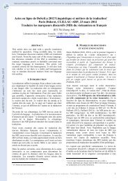
Chartered technology is a 130 nm CMOS one with various<br />
types of transis<strong>to</strong>rs: 3p3, 1p5, 1p5 low Vt. It builds TSV of 6<br />
µm length and 1,2 µm for <strong>the</strong> diameter. (See picture below,<br />
TSVs are called Super-Vias).<br />
Then Tezzaron performs <strong>the</strong> wafer connection with <strong>the</strong><br />
Cu-Cu <strong>the</strong>rmocompression bonding technique making both<br />
electrical and mechanical connections. The alignment<br />
between <strong>the</strong> two wafers is better than 2 µm. Next, <strong>the</strong> backside<br />
of one wafer is thinned up <strong>to</strong> reach <strong>the</strong> TSV contact: this<br />
wafer has about 12 µm thickness.<br />
Figure 1: Picture from Tezzaron website showing a three<br />
layers device<br />
In <strong>the</strong> picture above, we can see that <strong>the</strong> two first wafers<br />
from <strong>the</strong> bot<strong>to</strong>m have been stacked in a face-<strong>to</strong>-face process<br />
(Cu-Cu pads). Then <strong>the</strong> back-side of one wafer is thinned up<br />
<strong>to</strong> reach <strong>the</strong> TSV, Cu pads are placed on each TSV and this<br />
face becomes a new “front-side” for ano<strong>the</strong>r face-<strong>to</strong>-face<br />
stacked process. Also a large number of wafers can be<br />
stacked.
II. OMEGAPIX DESIGN<br />
OMEGAPIX <strong>circuit</strong> embeds 64x24 readout channels that<br />
have been developed <strong>to</strong> match very drastic requirements. In<strong>to</strong><br />
<strong>the</strong> first layer, called analogue tier, <strong>the</strong>re are <strong>the</strong> analogue part<br />
of <strong>the</strong> front-end cell, a block which performs <strong>the</strong> selection of<br />
<strong>the</strong> column and <strong>the</strong> bias. In<strong>to</strong> <strong>the</strong> o<strong>the</strong>r layer, called digital<br />
tier, <strong>the</strong>re is a shift register with a read logic in<strong>to</strong> each<br />
channel.<br />
A. Requirements<br />
Although one of goals of this first chip is <strong>to</strong> explore this<br />
new technology, as much <strong>the</strong> 130 nm CMOS process from<br />
Chartered as reliability and yield of <strong>3D</strong> devices from<br />
Tezzaron, requirements have been chosen in such a way <strong>the</strong>y<br />
go <strong>to</strong> <strong>the</strong> future likely requirements of <strong>the</strong> ATLAS upgrade<br />
Super LHC pixel project.<br />
So, we want <strong>to</strong> explore a new possibility <strong>to</strong> minimize <strong>the</strong><br />
pixel pitch down <strong>to</strong> 50x50 µm. Thus a readout array matching<br />
a new MPI-HLL plannar pixel sensor <strong>pro<strong>to</strong>type</strong> from Munich<br />
has been designed.<br />
Figure 2: pixel array sensor <strong>pro<strong>to</strong>type</strong><br />
Some specifications are given bellow:<br />
Channel size: 50x50 µm. The first limitation of <strong>the</strong> pixel<br />
size is currently <strong>the</strong> electronics readout area.<br />
Dissipation: 3 µW/ch. If we want <strong>to</strong> keep an equivalent<br />
power consumption after <strong>the</strong> pixel size shrinking, we have <strong>to</strong><br />
low drastically <strong>the</strong> power dissipation for each channel.<br />
Typically <strong>the</strong> consumption should be 2.4 µW/Ch <strong>to</strong> keep <strong>the</strong><br />
power density at 96 mW/cm². The power density has been<br />
low down <strong>to</strong> 80 mW/cm² (2 µW/ch) for <strong>the</strong> analogue tier and<br />
40 mW/cm² (1 µW/ch) for <strong>the</strong> digital tier.<br />
Noise: <strong>the</strong> IC has been designed <strong>to</strong> low <strong>the</strong> noise down <strong>to</strong><br />
100 e- and <strong>to</strong> be able <strong>to</strong> decrease <strong>the</strong> threshold down <strong>to</strong> 1000<br />
e-.<br />
B. Analogue Tier<br />
The analogue channel is divided in<strong>to</strong> three parts: <strong>the</strong><br />
preamplifier, <strong>the</strong> shaper with threshold tuning and <strong>the</strong><br />
discrimina<strong>to</strong>r.<br />
444<br />
The power voltage for all <strong>the</strong> analogue part, except for <strong>the</strong><br />
discrimina<strong>to</strong>r, is 1.2 V.<br />
Figure 3: analogue one channel schematic<br />
1) Preamplifier description<br />
In order <strong>to</strong> reach <strong>the</strong> very low power requirement and low<br />
channel area, design has been done in such a way that <strong>the</strong><br />
global capacitance has been minimized.<br />
Figure 4: preamplifier schematic<br />
The parasitic capacitance Cgd performs <strong>the</strong> feedback<br />
capacitance.<br />
Cf = Cgd = ~ 1.6 fF<br />
The ideal gain is 1/Cf = 100 mV/ke- or 625 mV/fC. In<br />
simulation, <strong>the</strong> gain is about 60 mV/ke- or 375 mV/fC. This<br />
lower value is due <strong>to</strong> <strong>the</strong> non infinite preamplifier open loop<br />
gain.<br />
The bias current are Ib1 = 100 pA, Ib2 = 2 nA, Ib3 = 1<br />
µA. A paraphase structure has been used <strong>to</strong> fix <strong>the</strong> DC points,<br />
equivalent <strong>to</strong> a non-inverting Common Source;<br />
transconductance = gm1.gm2/(gm1+gm2) depending of <strong>the</strong><br />
current.<br />
Rf = Req = ~180 MΩ if Ib1 = 100 pA<br />
Rf = Req = 74 MΩ if Ib1 = 1 nA
2) Shaper description<br />
The shaper has almost <strong>the</strong> same structure than <strong>the</strong><br />
preamplifier with a capacitive coupling but also with an<br />
additional variable gain and a 5 bits DAC <strong>to</strong> adjust <strong>the</strong> DC<br />
output and thus <strong>the</strong> threshold.<br />
Figure 5: shaper schematic<br />
The bias current are Ib1 = 2.5 nA, Ib2 = 5 nA, Ib3 = 60<br />
nA.<br />
The variable gain consist in four various NMOS in parallel<br />
which can be switched leading <strong>to</strong> make <strong>the</strong> global Cgd value<br />
<strong>to</strong> vary. So <strong>the</strong> gain varies from 172 mV/ke- <strong>to</strong> 487 mV/ke-,<br />
or from 1.075 V/fC <strong>to</strong> 3 V/fC.<br />
The DAC fixes <strong>the</strong> output DC voltage.<br />
3) The 5 bits DAC<br />
Since <strong>the</strong> high resistance poly option from Chartered was<br />
not taken, <strong>the</strong> DAC would have been designed with only<br />
transis<strong>to</strong>rs.<br />
Figure 6: 5 bits DAC schematic<br />
The principle of this DAC is not usual: two sets of diodes<br />
have been designed in such a way that <strong>the</strong> equivalent<br />
impedances are different. Four current sources can be selected<br />
445<br />
<strong>to</strong> make <strong>the</strong> current <strong>to</strong> vary. One bit selects <strong>the</strong> diode we want<br />
<strong>to</strong> use; <strong>the</strong> four o<strong>the</strong>r bits adjust <strong>the</strong> current which draws<br />
through <strong>the</strong> selected diode. The DAC value can vary from 460<br />
mV <strong>to</strong> 850 mV which is sufficient for tuning <strong>the</strong> threshold.<br />
4) Discrimina<strong>to</strong>r description<br />
The discrimina<strong>to</strong>r consists of three inverters. At first, this<br />
block should be in<strong>to</strong> <strong>the</strong> digital tier <strong>to</strong> minimize <strong>the</strong> bulk<br />
coupling between <strong>the</strong> discrimina<strong>to</strong>r and <strong>the</strong> preamplifier<br />
input. This design will be made in a next <strong>circuit</strong>.<br />
Discri input<br />
Output of <strong>the</strong> first<br />
inverter<br />
Output of <strong>the</strong><br />
second inverter<br />
Output of <strong>the</strong><br />
third inverter<br />
Vthn = 497 mV<br />
Vthp = - 470 mV<br />
VDD = 1 V<br />
Intrinsic threshold<br />
= 0.5 mV<br />
Figure 7: outputs after <strong>the</strong> three inverters<br />
5) Dedicated test chip<br />
This <strong>circuit</strong> has been design in such a way that it can be<br />
easy <strong>to</strong> test and measure <strong>the</strong> signals.<br />
Three probes have been added in<strong>to</strong> each analogue<br />
channels after <strong>the</strong> preamplifier, <strong>the</strong> shaper and <strong>the</strong><br />
discrimina<strong>to</strong>r <strong>to</strong> observe signals by oscilloscope.<br />
Several column types have been designed allowing us <strong>to</strong><br />
study various flavors of transis<strong>to</strong>r types (normal, low Vt,<br />
3p3), noise, oscillations…<br />
Column 1 <strong>to</strong> 10: reference channels<br />
Column 11 <strong>to</strong> 18: various preamplifier<br />
transis<strong>to</strong>r types have been <strong>integrated</strong><br />
Column 19 <strong>to</strong> 22: without variable gain<br />
Column 23: discrimina<strong>to</strong>r has been removed<br />
Column 24: shaper has been removed
Chx.x<br />
in_test<br />
(1 bit)<br />
Ctest<br />
Vref<br />
From <strong>the</strong><br />
previous<br />
channel<br />
24 columns, 64 channels/columns -> 1536 channels<br />
14 SC bits/channel -> 21504 SC bits<br />
2 SC bits/selectColumn -> 48 bits<br />
D Q D Q D Q<br />
D Q D Q<br />
clock<br />
probe_pa<br />
(1 bit)<br />
5 bits<br />
4 bits<br />
Valid_mask<br />
(1 bit)<br />
probe_sh<br />
(1 bit)<br />
probe_d<br />
(1 bit)<br />
64 channels<br />
Ch1.64<br />
Ch1.4<br />
Ch1.3<br />
Ch1.2<br />
Ch1.1<br />
To <strong>the</strong> next<br />
channel<br />
Ch2.64<br />
Ch2.4<br />
Ch2.3<br />
Ch2.2<br />
Ch2.1<br />
24 columns<br />
Ch24.64<br />
Ch24.4<br />
Ch24.3<br />
Ch24.2<br />
Ch24.1<br />
sel1 sel2 sel24<br />
• In_test -> 1 bit<br />
• 3 probes: preamplifier, shaper,<br />
discrimina<strong>to</strong>r -> 3 bits<br />
• DAC -> 5 bits<br />
• Shaper: variable gain -> 4 bits<br />
• Discrimina<strong>to</strong>r: mask -> 1 bit<br />
-> 14 SC bits / channel<br />
Figure 8: Slow Control in <strong>the</strong> analogue tier<br />
Three shift register for <strong>the</strong> slow control have been<br />
implemented. One <strong>to</strong> configure each analogue channels: test<br />
capacitance, DAC, variable gain, masked discrimina<strong>to</strong>r<br />
output, three probes. There are 14 bits for each channel and,<br />
with 1536 channels, this shift register has 21504 bits of slow<br />
control.<br />
Ano<strong>the</strong>r shift register has been implemented <strong>to</strong> configure<br />
<strong>the</strong> Select Column block: one bit <strong>to</strong> power or shut off <strong>the</strong><br />
column, ano<strong>the</strong>r bit <strong>to</strong> select <strong>the</strong> column in which <strong>the</strong> channel<br />
with selected probes is. This shift register has 48 bits of slow<br />
control.<br />
6) Simulations<br />
At this time <strong>the</strong> only results are simulations.<br />
Shaper<br />
DAC fixes <strong>the</strong> DC shaper<br />
output voltage and so <strong>the</strong><br />
threshold<br />
Preamplifier<br />
Vmax = Q/C => 60 mV<br />
(<strong>the</strong>oretically 100 mV for<br />
1000 e-)<br />
Transient response<br />
282 mV<br />
DAC: 1000<br />
Vth = 800 mV<br />
59.6 mV<br />
Noise at <strong>the</strong> output of <strong>the</strong> shaper<br />
Due <strong>to</strong> <strong>the</strong> parasitic capacitance<br />
S/N = 8<br />
Noise threshold = 100 e- <strong>to</strong><br />
130 e-<br />
Figure 9: simulation of <strong>the</strong> analogue channel<br />
2 MHz<br />
We can get a very high gain after <strong>the</strong> shaper, up <strong>to</strong> 3 V/fC.<br />
The simulated rms noise gives 16.2 mV, or 46 e-, which<br />
gives: S/N = 21.<br />
The figure below shows <strong>the</strong> linearity of <strong>the</strong> Time Over<br />
Threshold (TOT) for various injected charge.<br />
446<br />
Time Over Threshold (ns)<br />
900<br />
800<br />
700<br />
600<br />
500<br />
400<br />
300<br />
200<br />
100<br />
0<br />
Time Over Threshold measurement<br />
From this injected charge<br />
<strong>the</strong> shaper was saturated<br />
1000 2000 3000 4000 5000 6250 9375 12500<br />
Injected charge (e-)<br />
Ano<strong>the</strong>r little pulse has been<br />
observed after <strong>the</strong> main one<br />
TOT, gain = 0010, DAC<br />
= 0, 0000<br />
Shaper output<br />
Figure 10: TOT for different injected charge values<br />
threshold<br />
The TOT linearity is limited because <strong>the</strong> shaper output is<br />
rapidly saturated and oscillations can be observed which leads<br />
<strong>to</strong> introduce defaults in <strong>the</strong> effective time over threshold: <strong>the</strong><br />
shaper has been tuned for a little injection charge threshold,<br />
1000 electrons or 0,16 fC, but <strong>the</strong> typical injection charge will<br />
be significantly different with a sensor of about 200 µm<br />
thickness or about 75 µm.<br />
C. Digital Tier<br />
For <strong>the</strong> digital tier, <strong>the</strong> supply voltage was fixed <strong>to</strong> 1 V.<br />
Three parts divide this tier: a RS FlipFlop, a shift register<br />
of 24 DFlipFlops and a reading structure in<strong>to</strong> each digital<br />
channel placed just above <strong>the</strong> corresponding analogue<br />
channel.<br />
The digital tier has just been designed <strong>to</strong> get out <strong>the</strong> pulse<br />
coming from <strong>the</strong> discrimina<strong>to</strong>r and <strong>to</strong> create digital noise.<br />
One of <strong>the</strong> more important targets will be <strong>to</strong> examine <strong>the</strong><br />
coupling between <strong>the</strong> two tiers; and so, creating activity in<br />
digital tier will allow us <strong>to</strong> observe <strong>the</strong> behaviour of one layer<br />
when <strong>the</strong> neighbouring layer is working.<br />
From <strong>to</strong> <strong>the</strong><br />
analogue tier<br />
64 channels<br />
SR Flipflop<br />
RAZ<br />
SR Flipflop<br />
From <strong>to</strong> <strong>the</strong><br />
analogue tier S Q<br />
RAZ<br />
RN<br />
D Q D Q D Q D Q<br />
CLK (40 MHz)<br />
SR Flipflop<br />
From <strong>to</strong> <strong>the</strong><br />
analogue tier S Q<br />
RAZ<br />
RN<br />
D Q D Q D Q D Q<br />
CLK (40 MHz)<br />
S Q D Q D Q D Q D Q<br />
RN<br />
CLK (40 MHz)<br />
24 DFlipflops<br />
24 DFlipflops<br />
24 columns<br />
24 DFlipflops<br />
D_r<br />
CK_r<br />
D_r<br />
CK_r<br />
D Q<br />
D Q<br />
D_r<br />
CK_r<br />
NAND<br />
NAND<br />
D<br />
Q<br />
Q_r<br />
D_r<br />
Q_r<br />
D_r<br />
out<br />
NAND<br />
Q_r<br />
D_r<br />
1536 channels, 24<br />
columns, 64 ch/col<br />
Figure 11: digital channel schematic<br />
Read bus<br />
on out pad<br />
Go <strong>to</strong> <strong>the</strong> next<br />
channel D_r pin<br />
Only one channel output can be<br />
viewed on <strong>the</strong> same time
A shift register in<strong>to</strong> <strong>the</strong> digital tier has been implemented<br />
<strong>to</strong> select <strong>the</strong> channel we want <strong>to</strong> read. This shift register has<br />
1536 bits of shift register.<br />
D. Power consumption<br />
The power consumption for one channel, in simulation, is<br />
about 1.75 µW/ch, below <strong>the</strong> requirement.<br />
III. TEST BOARD<br />
A test board has been designed with a specific firmware<br />
<strong>to</strong> control <strong>the</strong> chip I/O. A LabView software manages <strong>the</strong><br />
board.<br />
It is possible <strong>to</strong> observe and measure <strong>the</strong> influence of<br />
coupling between <strong>the</strong> digital tier and <strong>the</strong> analogue tier.<br />
447<br />
The three probes allow us <strong>to</strong> observe <strong>the</strong> signals after <strong>the</strong><br />
preamplifier, <strong>the</strong> shaper and <strong>the</strong> discrimina<strong>to</strong>r by oscilloscope.<br />
To characterize <strong>the</strong> discrimina<strong>to</strong>rs S-Curve measurements<br />
will be made.<br />
IV. REFERENCES<br />
[1]: Handbook of <strong>3D</strong> Integration, Technology and<br />
applications of <strong>3D</strong> Integrated Circuits, edited by Philip<br />
Garrou, Chris<strong>to</strong>pher Bower and Peter Ramm.<br />
[2]: website of <strong>3D</strong>IC at Fermilab, http://3dic.fnal.gov


![[tel-00433556, v1] Relation entre Stress Oxydant et Homéostasie ...](https://img.yumpu.com/19233319/1/184x260/tel-00433556-v1-relation-entre-stress-oxydant-et-homeostasie-.jpg?quality=85)