Smart Highside Power Switch - Farnell
Smart Highside Power Switch - Farnell
Smart Highside Power Switch - Farnell

Create successful ePaper yourself
Turn your PDF publications into a flip-book with our unique Google optimized e-Paper software.
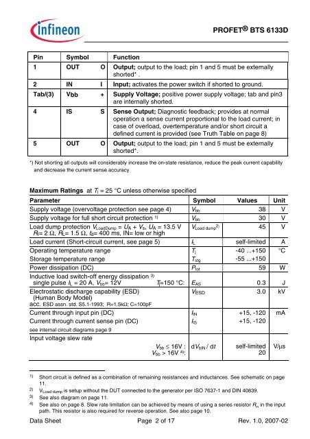
Pin Symbol Function<br />
PROFET® BTS 6133D<br />
1 OUT O Output; output to the load; pin 1 and 5 must be externally<br />
shorted* .<br />
2 IN I Input; activates the power switch if shorted to ground.<br />
Tab/(3) Vbb + Supply Voltage; positive power supply voltage; tab and pin3<br />
are internally shorted.<br />
4 IS S Sense Output; Diagnostic feedback; provides at normal<br />
operation a sense current proportional to the load current; in<br />
case of overload, overtemperature and/or short circuit a<br />
defined current is provided (see Truth Table on page 8)<br />
5 OUT O Output; output to the load; pin 1 and 5 must be externally<br />
shorted*.<br />
*) Not shorting all outputs will considerably increase the on-state resistance, reduce the peak current capability<br />
and decrease the current sense accuracy<br />
Maximum Ratings at Tj = 25 °C unless otherwise specified<br />
Parameter Symbol Values Unit<br />
Supply voltage (overvoltage protection see page 4) Vbb 38 V<br />
Supply voltage for full short circuit protection 1) Vbb 30 V<br />
Load dump protection VLoadDump = UA + Vs, UA = 13.5 V<br />
RI= 2 Ω, RL= 1.5 Ω, td= 400 ms, IN= low or high<br />
VLoad dump 2) 45 V<br />
Load current (Short-circuit current, see page 5) IL self-limited A<br />
Operating temperature range<br />
Tj<br />
-40 ...+150 °C<br />
Storage temperature range<br />
Tstg<br />
-55 ...+150<br />
<strong>Power</strong> dissipation (DC) Ptot 59 W<br />
Inductive load switch-off energy dissipation 3)<br />
single pulse IL = 20 A, Vbb= 12V Tj=150 °C:<br />
Electrostatic discharge capability (ESD)<br />
(Human Body Model)<br />
acc. ESD assn. std. S5.1-1993; R=1.5kΩ; C=100pF<br />
Current through input pin (DC)<br />
Current through current sense pin (DC)<br />
see internal circuit diagrams page 9<br />
Input voltage slew rate<br />
Vbb ≤ 16V :<br />
Vbb > 16V 4) :<br />
EAS 0.3 J<br />
3.0 kV<br />
VESD<br />
Data Sheet Page 2 of 17 Rev. 1.0, 2007-02<br />
IIN<br />
IIS<br />
+15, -120<br />
+15, -120<br />
mA<br />
dVbIN / dt self-limited<br />
20 V/µs<br />
1) Short circuit is defined as a combination of remaining resistances and inductances. See schematic on page<br />
11.<br />
2) VLoad dump is setup without the DUT connected to the generator per ISO 7637-1 and DIN 40839.<br />
3) See also diagram on page 11.<br />
4) See also on page 8. Slew rate limitation can be achieved by means of using a series resistor RIN in the input<br />
path. This resistor is also required for reverse operation. See also page 10.