SPEAKERS - Goldmund
SPEAKERS - Goldmund
SPEAKERS - Goldmund

Create successful ePaper yourself
Turn your PDF publications into a flip-book with our unique Google optimized e-Paper software.
<strong>Goldmund</strong> White Paper<br />
<strong>SPEAKERS</strong><br />
The materials, manufacturing techniques, and design concepts behind <strong>Goldmund</strong><br />
speakers<br />
When designing speakers, <strong>Goldmund</strong> engineers use<br />
computer-based modeling, which takes into account<br />
the characteristics of the speaker drivers and<br />
enclosure and allows them to perfect the speaker’s<br />
acoustical performance. While we do listen to various<br />
prototypes during the design process to judge the<br />
efficacy of engineering changes, we design and build<br />
our speakers primarily to meet strict technical<br />
standards, not to suit the taste of a particular<br />
listener’s ears.<br />
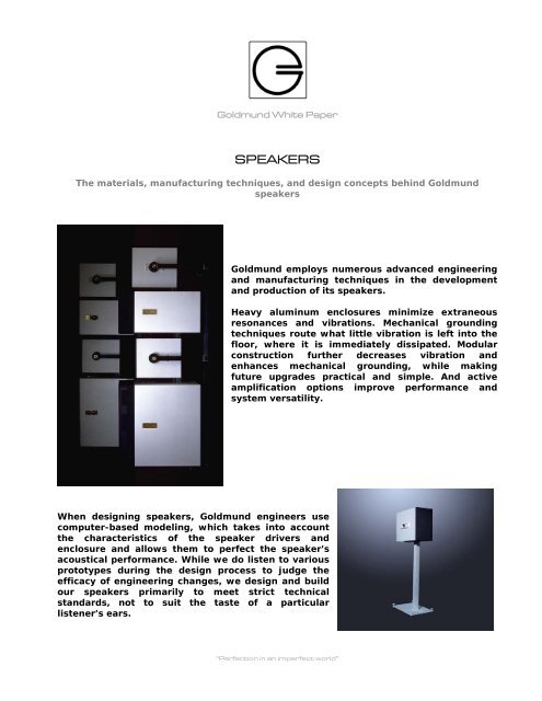
<strong>Goldmund</strong> employs numerous advanced engineering<br />
and manufacturing techniques in the development<br />
and production of its speakers.<br />
Heavy aluminum enclosures minimize extraneous<br />
resonances and vibrations. Mechanical grounding<br />
techniques route what little vibration is left into the<br />
floor, where it is immediately dissipated. Modular<br />
construction further decreases vibration and<br />
enhances mechanical grounding, while making<br />
future upgrades practical and simple. And active<br />
amplification options improve performance and<br />
system versatility.<br />
“Perfection in an imperfect world”
Aluminum enclosures<br />
Extraneous vibration is one of the most challenging<br />
problems in loudspeaker design. The intent of the<br />
speaker designer is that only the cones of a speaker’s<br />
woofers and the domes of its tweeters produce sound<br />
waves. If a loudspeaker cabinet vibrates along with the<br />
woofers and tweeters, it contributes unwanted sounds of<br />
its own. The unwanted sound waves may partially cancel<br />
certain audio frequencies and reinforce others, creating<br />
an uneven frequency response and an unnatural sound.<br />
A vibrating speaker cabinet also acts as an acoustical<br />
“spring,” absorbing sound from the back of the woofers<br />
then re-radiating it into the cabinet and out through the<br />
ports to the listener.<br />
The result is that sounds “ring”. In other words, the<br />
speaker continues to emit a musical note long after the<br />
note was supposed to end. This emission has two<br />
deleterious effects: It smears the musical note, spoken<br />
dialogue, or special effect being played; and it obscures<br />
the attack of the sound that follows.<br />
Most speaker enclosures are built from medium-density fiberboard (MDF), a wood-based material<br />
that, while much less resonant than natural wood panels or plywood, still vibrates relatively<br />
easily.<br />
<strong>Goldmund</strong> has chosen to build its speaker cabinets from a superior, although much more costly<br />
material: dense slabs of aluminum measuring at least one-half of an inch thick. Aluminum bracing<br />
inside the speaker cabinet further reduces what little vibration exists.<br />
The use of aluminum results in a speaker that is heavier and denser than most speakers of<br />
comparable size. The result of this robust construction is a more natural, clean, and uncolored<br />
sound.<br />
“Perfection in an imperfect world”
Modular construction<br />
All <strong>Goldmund</strong> speakers are built in modular fashion, which<br />
both improves their sound and allows easy upgrades later<br />
(Signature versions). Each speaker module is sized ideally<br />
for its purpose, and using multiple smaller cabinets<br />
reduces resonance and vibration when compared with a<br />
single larger enclosure.<br />
If more modules are desired—to add, perhaps, a centerchannel<br />
speaker, or to augment bass response—multiple<br />
modules can be combined in metal rack systems. These<br />
racks hold each module in the proper position for ideal<br />
acoustical performance and firm mechanical grounding.<br />
The Epilogue system offers great expansion capabilities.<br />
The system’s core component is the relatively small<br />
Epilogue 1 speaker or Epilogue 1 Signature.<br />
For more bass response, Epilogue 2 or Epilogue 2 Signature bass modules may be added. The Full<br />
Epilogue system extends bass response even deeper with the addition of the Epilogue 3 Signature<br />
subwoofer modules and an additional Epilogue 1 in each rack to increase the acoustical output for<br />
stereo listening, and to reproduce center-channel sound in home theater systems.<br />
Internal amplification<br />
Passive speakers are the best choice for those who prefer to select the power and quality of their<br />
amplifiers. These speakers also allow easy upgrading of a system to more powerful amplifiers<br />
when the need for greater output and sonic precision arises.<br />
The <strong>Goldmund</strong> Metis 10 Acoustic Processor and Metis Active Speakers<br />
“Perfection in an imperfect world”<br />
Active speakers are best for<br />
those who prefer to leave all<br />
of the specification to<br />
<strong>Goldmund</strong>. The amplifiers in<br />
these speakers are designed<br />
expressly to meet the demand<br />
presented by the speaker<br />
drivers. <strong>Goldmund</strong> speakers’<br />
enclosures make comfortable<br />
homes for these amplifiers;<br />
the extraordinary thermal<br />
mass of the thick aluminum<br />
enclosures eliminates the<br />
need for amplifier ventilation<br />
and cooling fins.
Because of the additional demands placed on subwoofer amplifiers, <strong>Goldmund</strong>’s Epilogue 3<br />
subwoofer module is internally powered to ensure maximum performance and reliability.<br />
<strong>Goldmund</strong> Media Room applications<br />
Although most of <strong>Goldmund</strong>’s speakers are designed for freestanding use, a new line of modular<br />
speakers has been created for in-wall and home theater applications. The available modules are<br />
the U-Logos 1 main speaker, the U-Logos 2 woofer module, and the U-Logos 3 subwoofer.<br />
All of the modules are designed to be mounted in a wall, with an acoustically transparent<br />
decorative fabric of the homeowner’s choice covering the speaker. The shapes and dimensions of<br />
the U-Logos speakers may also be customized to fit into any space with sufficient volume.<br />
The U-Logos Media Room speakers are unusual in that they are specifically designed for use with<br />
an external power amplifier/crossover. <strong>Goldmund</strong> has created a Media Room amplifier that<br />
combines amplification circuitry of the same quality found in <strong>Goldmund</strong>’s freestanding amplifiers<br />
with a digital signal processor that performs crossover functions. Each driver in each Media Room<br />
speaker is assigned its own amplifier channel, with a power rating of 580 W if the amplifier is run<br />
in mono mode, and 290 W per channel if the amplifier is run in stereo mode. The DSP contours<br />
the sound to suit that driver’s characteristics—i.e., tweeters receive only high-frequency sound,<br />
while woofers receive only low frequencies.<br />
Related web pages:<br />
<strong>Goldmund</strong> Epilogue Speakers:<br />
http://www.goldmund.com/products/epilogue_1<br />
http://www.goldmund.com/products/epilogue_1_2<br />
http://www.goldmund.com/products/epilogue_full_system<br />
Metis Speakers and Subwoofer:<br />
http://www.goldmund.com/products/metis_speaker<br />
http://www.goldmund.com/products/metis_sub<br />
“Perfection in an imperfect world”
<strong>Goldmund</strong> White Paper<br />
<strong>SPEAKERS</strong><br />
MODELING PROCEDURE<br />
With the aim of ensuring the perfect<br />
functioning of our loudspeaker systems, we<br />
have implemented a modeling procedure<br />
enabling any component, as well as the whole<br />
systems themselves, to be under control.<br />
This procedure allows us to be very efficient in<br />
case of driver and filter modification or<br />
replacement. On top of that, it allows any<br />
possible problems encounter by our dealers to<br />
be analysed with the aim of correcting them.<br />
Finally, it will constitute a sound theoretical<br />
basis for any of our future loudspeaker system<br />
development.<br />
“Perfection in an imperfect world”
The procedure comprises 5 steps, which are explained below with examples:<br />
1. Thiele and Small parameter measurements (added-mass method)<br />
2. Preliminary calculations:<br />
- Electrical, mechanical and acoustical lumped-constant parameters<br />
- Input impedance, volume velocity and membrane displacement (infinite baffle,<br />
closed-box, vented-box...)<br />
- First estimation of drivers and port radiating sound pressure<br />
3. Crossover modeling and transfer function calculation<br />
4. Modeling comprising crossover, driver and enclosure lumped-constant parameters:<br />
- Input impedance with and without cross-over<br />
- Volume velocities with and without cross-over<br />
5. Final loudspeaker system calculations:<br />
- Introduction of the modelled filtered volume velocities into calculation code<br />
- Calculation of the loudspeaker system sound pressure in amplitude and phase,<br />
taking into account driver finite radiating surface and diffraction at the enclosure<br />
edges<br />
To sum up, this procedure offers various possible loudspeaker response calculations, allowing our<br />
systems to be studied and analysed in different ways depending upon the application under<br />
consideration:<br />
- Loudspeaker system input impedance (amplitude and phase)<br />
- Electrical impedance at any location, like for example at the driver terminals<br />
- Volume velocities in amplitude and phase (active and passive drivers, port…)<br />
- X-over transfer functions<br />
- Sound pressure level valid in the near field as well as in the far field, and taking into<br />
account the diffraction at the enclosure edges (GTD and UTD methods)<br />
- Sound pressure phase and group delay (active and passive drivers, port,<br />
loudspeaker system)<br />
“Perfection in an imperfect world”
STEPS DETAILED EXPLICATIONS WITH EXAMPLES<br />
1. Thiele and Small parameter measurements (added-mass method)<br />
This well-known method enables the TS parameters to be measured without test enclosure. The<br />
measurement is carried out manually and/or automatically to ensure a high level of accuracy.<br />
The figure below shows an example of automatic measurement (Logos Sub active driver).<br />
10<br />
8<br />
6<br />
4<br />
2<br />
0<br />
10 1<br />
10 2<br />
LOGOS SUB<br />
Coming from the average of several driver measurements, the TS parameters (Re, Le, fs, Qms, Qes,<br />
Qts, Vas) are finally compared with the constructor ones before being introduced in calculation<br />
code.<br />
“Perfection in an imperfect world”<br />
10 3<br />
10 4<br />
Hz
2. Preliminary calculations<br />
First we need to determine:<br />
- The force factor Bl<br />
- The mechanical parameters linked to the mobile system: mass ms, resistance Rms and<br />
compliance Cms<br />
- The acoustic equivalent parameters of enclosure, port and losses due to leakage: Cab,<br />
map, Rleak<br />
- The acoustical radiation impedance mar and Rar<br />
These lumped-constant parameters enable input impedance, membrane displacement, as well as<br />
drivers and port volume velocities to be calculated. According to the hypotheses of membrane<br />
coincidence and monopole radiation, they lead to a first estimation of drivers and port radiating<br />
sound pressure.<br />
The figure below shows the example of the Minilogos calculation results:<br />
ohm<br />
m3/s<br />
35<br />
30<br />
25<br />
20<br />
15<br />
10<br />
5<br />
0<br />
6<br />
5<br />
4<br />
3<br />
2<br />
1<br />
0<br />
- Drivers input impedances<br />
- Drivers membrane displacements<br />
- Port and drivers volume velocities<br />
- Port and drivers radiating sound pressure estimated at 1W/1m<br />
DRIVERS INPUT IMPEDANCE<br />
10 2<br />
x 10 -3 PORT & DRIVERS VOLUME VELOCITY<br />
10 2<br />
10 3<br />
Hz<br />
10 3<br />
Hz<br />
10 4<br />
10 4<br />
mm<br />
dB SPL<br />
2.5<br />
“Perfection in an imperfect world”<br />
2<br />
1.5<br />
1<br />
0.5<br />
0<br />
100<br />
95<br />
90<br />
85<br />
80<br />
75<br />
70<br />
65<br />
60<br />
55<br />
50<br />
DRIVERS MEMBRANE DISPLACEMENT<br />
10 2<br />
PORT & DRIVERS SOUND PRESSURE at 1W/1m<br />
10 2<br />
10 3<br />
Hz<br />
10 3<br />
Hz<br />
10 4<br />
10 4
3. Crossover modeling and transfer function calculation<br />
The above calculation of port and drivers sound pressure radiated at 1W/1m, enables the<br />
crossover cut-off frequencies and slopes to be estimated.<br />
The figures below show the example of the MiniLogos crossover modeling and transfer function<br />
calculation.<br />
Vm<br />
Vtw<br />
Rg<br />
1 2<br />
0<br />
Rg<br />
1 2<br />
0<br />
V+<br />
V+<br />
1<br />
Cm<br />
2<br />
1<br />
Rm<br />
2<br />
2<br />
1<br />
Cm1<br />
1<br />
2<br />
Rm2<br />
1<br />
Lm<br />
Rem<br />
2<br />
V+<br />
2<br />
V- V-<br />
1<br />
Rtw<br />
2<br />
1<br />
Ctw<br />
1 2<br />
1<br />
Ltw<br />
2<br />
Rtw2<br />
2<br />
V- V-<br />
1<br />
1<br />
V+<br />
Retw<br />
2<br />
10<br />
dB<br />
0<br />
Hz<br />
10 100 1000 10000 100000<br />
-10<br />
-20<br />
-30<br />
-40<br />
-50<br />
-60<br />
-70<br />
-80<br />
4. Modeling comprising crossover, driver and enclosure lumped-constant<br />
parameters<br />
The points 2 and 3 lead to the final system modeling. The latter enable the filtered input<br />
impedance and volume velocities to be calculated.<br />
The figures below show the MiniLogos final modeling and the resulting calculated filtered input<br />
impedance and volume velocities:<br />
Vwr<br />
Rg0r<br />
Rtwr<br />
0<br />
Cmr<br />
Rmr<br />
Ctwr<br />
Rem0r<br />
Cm1r<br />
Rm2r<br />
R3r<br />
Ltwr<br />
R2r<br />
Lmr<br />
Lemr<br />
+ -<br />
-Bl<br />
Bl<br />
+<br />
-<br />
msmr<br />
Rsmr<br />
Csmr<br />
+<br />
-<br />
+<br />
-<br />
Sd<br />
Rtw2r Re_twr Letwr<br />
mstwr Rstwr Cstwr<br />
martwr<br />
“Perfection in an imperfect world”<br />
+ -<br />
0<br />
Bl<br />
+<br />
-<br />
-Bl<br />
0<br />
-Sd<br />
marmr<br />
+<br />
-<br />
+<br />
-<br />
Sd<br />
Cabwr<br />
0<br />
-Sd<br />
Rapwr<br />
0<br />
mapwr
ohm<br />
deg<br />
deg<br />
35<br />
30<br />
25<br />
20<br />
15<br />
10<br />
5<br />
0<br />
-50<br />
m3/s<br />
50<br />
10 1<br />
0<br />
10 1<br />
6<br />
5<br />
4<br />
3<br />
2<br />
1<br />
10 1<br />
0<br />
150<br />
100<br />
50<br />
0<br />
-50<br />
-100<br />
-150<br />
10 2<br />
10 2<br />
10 2<br />
x 10 -3 VOLUME VELOCITIES (medium & port)<br />
10 1<br />
10 2<br />
MINILOGOS INPUT IMPEDANCE<br />
10 3<br />
10 3<br />
Hz<br />
Hz<br />
deg<br />
m3/s<br />
10 3<br />
0<br />
10 3<br />
10 3<br />
“Perfection in an imperfect world”<br />
6<br />
5<br />
4<br />
3<br />
2<br />
1<br />
150<br />
100<br />
50<br />
0<br />
-50<br />
-100<br />
-150<br />
10 4<br />
10 4<br />
x 10 -5 VOLUME VELOCITIES (tweeter)<br />
10 3<br />
10 4<br />
10 4
5. Final loudspeaker system calculations<br />
The modeled volume velocities of drivers and port are introduced in the calculation with the aim<br />
of calculating the sound pressure radiated by the loudspeaker system.<br />
The sound pressure is then calculated in amplitude and phase taking into account the driver finite<br />
radiating surface, the drivers and port locations in the enclosure and the diffraction at the<br />
enclosure edges (GTD / UTD methods). The figure below shows the MiniLogos sound pressure<br />
level at 1W/1m with and without box edges diffraction calculation:<br />
dB SPL<br />
dB SPL<br />
deg<br />
100<br />
80<br />
60<br />
40<br />
20<br />
0<br />
100<br />
80<br />
60<br />
40<br />
20<br />
0<br />
3<br />
2<br />
1<br />
0<br />
-1<br />
-2<br />
-3<br />
Without edges diffraction<br />
10 2<br />
10 2<br />
10 2<br />
Hz<br />
Hz<br />
Hz<br />
10 3<br />
10 3<br />
10 3<br />
10 4<br />
10 4<br />
10 4<br />
dB SPL<br />
dB SPL<br />
deg<br />
100<br />
80<br />
60<br />
40<br />
20<br />
“Perfection in an imperfect world”<br />
0<br />
100<br />
80<br />
60<br />
40<br />
20<br />
0<br />
3<br />
2<br />
1<br />
0<br />
-1<br />
-2<br />
-3<br />
10 2<br />
10 2<br />
10 2<br />
With edges diffraction<br />
Hz<br />
Hz<br />
Hz<br />
10 3<br />
10 3<br />
10 3<br />
10 4<br />
10 4<br />
10 4
The irregularities are calculated in order to compensate those of the driver. Thus, in case of a new<br />
loudspeaker system development, it is necessary to measure the driver frequency responses<br />
(baffle assembly). It is also necessary of course to measure the final product in an anechoic<br />
chamber in order to validate the calculation procedure.<br />
Finally, it should be noted that the sound pressure phase derivative enables the group delay to be<br />
calculated with a great accuracy. This last loudspeaker response is very important for the<br />
development of in-phase drivers and analysis of fast response systems.<br />
ms<br />
18<br />
16<br />
14<br />
12<br />
10<br />
8<br />
6<br />
4<br />
2<br />
0<br />
10 2<br />
MINILOGOS GROUP DELAY CALCULATED at 1m<br />
Hz<br />
10 3<br />
“Perfection in an imperfect world”<br />
10 4