SPEAKERS - Goldmund
SPEAKERS - Goldmund
SPEAKERS - Goldmund

Create successful ePaper yourself
Turn your PDF publications into a flip-book with our unique Google optimized e-Paper software.
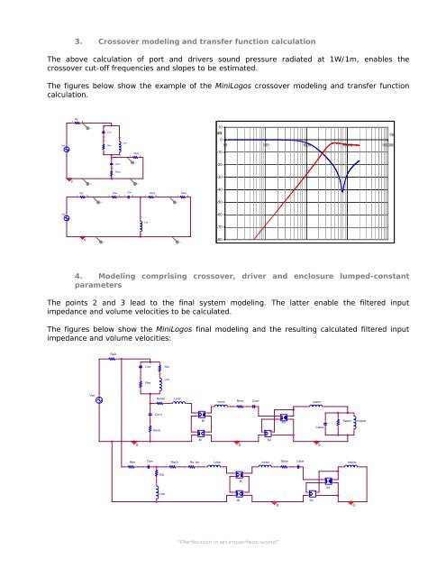
3. Crossover modeling and transfer function calculation<br />
The above calculation of port and drivers sound pressure radiated at 1W/1m, enables the<br />
crossover cut-off frequencies and slopes to be estimated.<br />
The figures below show the example of the MiniLogos crossover modeling and transfer function<br />
calculation.<br />
Vm<br />
Vtw<br />
Rg<br />
1 2<br />
0<br />
Rg<br />
1 2<br />
0<br />
V+<br />
V+<br />
1<br />
Cm<br />
2<br />
1<br />
Rm<br />
2<br />
2<br />
1<br />
Cm1<br />
1<br />
2<br />
Rm2<br />
1<br />
Lm<br />
Rem<br />
2<br />
V+<br />
2<br />
V- V-<br />
1<br />
Rtw<br />
2<br />
1<br />
Ctw<br />
1 2<br />
1<br />
Ltw<br />
2<br />
Rtw2<br />
2<br />
V- V-<br />
1<br />
1<br />
V+<br />
Retw<br />
2<br />
10<br />
dB<br />
0<br />
Hz<br />
10 100 1000 10000 100000<br />
-10<br />
-20<br />
-30<br />
-40<br />
-50<br />
-60<br />
-70<br />
-80<br />
4. Modeling comprising crossover, driver and enclosure lumped-constant<br />
parameters<br />
The points 2 and 3 lead to the final system modeling. The latter enable the filtered input<br />
impedance and volume velocities to be calculated.<br />
The figures below show the MiniLogos final modeling and the resulting calculated filtered input<br />
impedance and volume velocities:<br />
Vwr<br />
Rg0r<br />
Rtwr<br />
0<br />
Cmr<br />
Rmr<br />
Ctwr<br />
Rem0r<br />
Cm1r<br />
Rm2r<br />
R3r<br />
Ltwr<br />
R2r<br />
Lmr<br />
Lemr<br />
+ -<br />
-Bl<br />
Bl<br />
+<br />
-<br />
msmr<br />
Rsmr<br />
Csmr<br />
+<br />
-<br />
+<br />
-<br />
Sd<br />
Rtw2r Re_twr Letwr<br />
mstwr Rstwr Cstwr<br />
martwr<br />
“Perfection in an imperfect world”<br />
+ -<br />
0<br />
Bl<br />
+<br />
-<br />
-Bl<br />
0<br />
-Sd<br />
marmr<br />
+<br />
-<br />
+<br />
-<br />
Sd<br />
Cabwr<br />
0<br />
-Sd<br />
Rapwr<br />
0<br />
mapwr