2-D wavelength demultiplexer with potential for >= 1000 channels in ...
2-D wavelength demultiplexer with potential for >= 1000 channels in ...
2-D wavelength demultiplexer with potential for >= 1000 channels in ...

You also want an ePaper? Increase the reach of your titles
YUMPU automatically turns print PDFs into web optimized ePapers that Google loves.
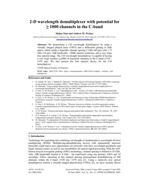
2-D <strong>wavelength</strong> <strong>demultiplexer</strong> <strong>with</strong> <strong>potential</strong> <strong>for</strong><br />
≥ <strong>1000</strong> <strong>channels</strong> <strong>in</strong> the C-band<br />
Shijun Xiao and Andrew M. We<strong>in</strong>er<br />
School of Electrical & Computer Eng<strong>in</strong>eer<strong>in</strong>g, Purdue University, West Lafayette, IN 47907-1285, U.S.A.<br />
sxiao@ecn.purdue.edu, amw@ecn.purdue.edu<br />
Abstract: We demonstrate a 2-D <strong>wavelength</strong> <strong>demultiplexer</strong> by us<strong>in</strong>g a<br />
virtually imaged phased array (VIPA) and a diffraction grat<strong>in</strong>g <strong>in</strong> bulk<br />
optics, which yields a hyperf<strong>in</strong>e channel spac<strong>in</strong>g 5 GHz (40 pm) <strong>with</strong> 1.75<br />
GHz (14 pm) -3dB bandwidth, >20dB channel isolations, and a very large<br />
free spectral range. The 2-D <strong>wavelength</strong> <strong>demultiplexer</strong> is capable of hav<strong>in</strong>g<br />
a very large number (≥<strong>1000</strong>) of hyperf<strong>in</strong>e <strong>channels</strong> <strong>in</strong> the C-band (1530 -<br />
1570 nm). We also present the first analytic theory <strong>for</strong> the 2-D<br />
<strong>demultiplexer</strong>.<br />
©2004 Optical Society of America<br />
OCIS codes: (060.2330) Fiber optics communications, (060.1810) Couplers, switches, and<br />
multiplexers<br />
References and L<strong>in</strong>ks<br />
1. K. Takada, M. Abe, T. Shibata, K. Okamoto, “10-GHz-spaced 1010-channel tandem AWG filter consist<strong>in</strong>g<br />
of one primary and ten secondary AWGs,” IEEE Photon. Technol. Lett. 13, 577-578 (2001).<br />
2. M. Shirasaki, “Large angular dispersion by a virtually imaged phased array and its application to a<br />
<strong>wavelength</strong> <strong>demultiplexer</strong>,” Opt. Lett. 21, 366-368 (1996).<br />
3. S. Xiao, A. M. We<strong>in</strong>er, C. L<strong>in</strong>, “Demultiplexers <strong>with</strong> ~ 10 pm (1.25 GHz) -3dB transmission bandwidth<br />
us<strong>in</strong>g a virtually imaged phased array (VIPA),” TuL1, Optical Fiber Communication Conference, (Optical<br />
Society of America, Wash<strong>in</strong>gton D.C., 2004).<br />
4. S. Xiao, A. M. We<strong>in</strong>er, C. L<strong>in</strong>, “Experimental and theoretical study of Hyperf<strong>in</strong>e WDM Demultiplexer<br />
per<strong>for</strong>mance us<strong>in</strong>g the virtually-imaged phased-array (VIPA),” submitted to IEEE/OSA J. Lightwave<br />
Technol.<br />
5. S. Xiao, J. D. McK<strong>in</strong>ney, A. M. We<strong>in</strong>er, “Photonic microwave arbitrary wave<strong>for</strong>m generation us<strong>in</strong>g a<br />
virtually-imaged phased-array (VIPA) direct space-to-time pulse shaper,” <strong>in</strong> press, IEEE Photon. Technol.<br />
Lett. (2004).<br />
6. A. M. We<strong>in</strong>er, “Femtosecond pulse shap<strong>in</strong>g us<strong>in</strong>g spatial light modulators,” Rev. Sci. Instrum. 71, 1929-<br />
1960 (2000).<br />
7. R. D. Nelson, D. E. Leaird, A. M. We<strong>in</strong>er, “Programmable polarization-<strong>in</strong>dependent spectral phase<br />
compensation and pulse shap<strong>in</strong>g,” Opt. Express, 11, 1763-1769 (2003).<br />
8. M. Shirasaki, “Compensation of chromatic dispersion and dispersion slope us<strong>in</strong>g a virtually imaged phased<br />
array”, TuS1, Optical Fiber Communication Conference, (Optical Society of America, Wash<strong>in</strong>gton D.C.,<br />
2001).<br />
9. S. Xiao, A. M. We<strong>in</strong>er, C. L<strong>in</strong>, “A dispersion law <strong>for</strong> virtually-imaged phased-array (VIPA) spectral<br />
dispersers based on paraxial wave theory,” IEEE J. Quantum Electron. 40, 420- 426 (2004).<br />
1. Introduction<br />
Technology <strong>for</strong> separat<strong>in</strong>g and comb<strong>in</strong><strong>in</strong>g <strong>wavelength</strong>s is fundamental to <strong>wavelength</strong> division<br />
multiplex<strong>in</strong>g (WDM). Multiplex<strong>in</strong>g-demultiplex<strong>in</strong>g devices <strong>with</strong> substantially narrower<br />
l<strong>in</strong>ewidth could lead to new opportunities <strong>for</strong> networks <strong>with</strong> f<strong>in</strong>er <strong>wavelength</strong> granularity and<br />
larger channel counts, as well as new possibilities <strong>for</strong> optical signal process<strong>in</strong>g. With the wellknown<br />
arrayed waveguide grat<strong>in</strong>g (AWG) technology, channel spac<strong>in</strong>g is limited to 10 GHz,<br />
<strong>with</strong> -3dB bandwidth limited to 4 GHz. An experiment us<strong>in</strong>g one primary AWG and 10<br />
secondary AWGs operat<strong>in</strong>g at this channel spac<strong>in</strong>g demonstrated demultiplex<strong>in</strong>g of 500<br />
<strong>channels</strong> <strong>with</strong><strong>in</strong> the C-band (1530 nm -1570 nm) [1]. Us<strong>in</strong>g a relatively new optical<br />
<strong>demultiplexer</strong> termed a virtually-imaged phased-array (VIPA) [2], we have recently shown<br />
#4392 - $15.00 US Received 20 May 2004; revised 14 June 2004; accepted 15 June 2004<br />
(C) 2004 OSA 28 June 2004 / Vol. 12, No. 13 / OPTICS EXPRESS 2895
very narrow demultiplex<strong>in</strong>g l<strong>in</strong>ewidths, <strong>with</strong> -3dB bandwidths of 1 and 2 GHz (8 and 16 pm)<br />
<strong>for</strong> 50 and 100 GHz free spectral range (FSR) devices, respectively [3, 4]. This narrow<br />
l<strong>in</strong>ewidth capability makes the VIPA attractive <strong>for</strong> applications <strong>in</strong> hyperf<strong>in</strong>e WDM and <strong>in</strong><br />
femtosecond pulse shap<strong>in</strong>g <strong>with</strong> unusually large time apertures (~1 ns) [5]. For the VIPA<br />
<strong>demultiplexer</strong>, the narrow -3dB bandwidths are l<strong>in</strong>ked to a periodic spectral dispersion<br />
behavior <strong>with</strong> relatively low FSR; this strongly limits the channel counts available <strong>for</strong><br />
<strong>wavelength</strong> division multiplex<strong>in</strong>g applications. Recently, a comb<strong>in</strong>ation of a VIPA and a<br />
diffraction grat<strong>in</strong>g has been used <strong>in</strong> a Fourier pulse shap<strong>in</strong>g geometry [6, 7] to implement a<br />
chromatic dispersion compensation system <strong>with</strong> varied dispersion slope <strong>for</strong> different WDM<br />
<strong>channels</strong> [8], where the VIPA separates <strong>wavelength</strong> components <strong>with</strong><strong>in</strong> a s<strong>in</strong>gle WDM<br />
channel <strong>in</strong> one dimension, and the diffraction grat<strong>in</strong>g separates different WDM <strong>channels</strong> <strong>in</strong>to<br />
another dimension. Here, <strong>for</strong> the first time to our knowledge, we <strong>in</strong>vestigate the 2-D<br />
<strong>wavelength</strong> demultiplex<strong>in</strong>g per<strong>for</strong>mance of this approach. We demonstrate 1.75 GHz -3dB<br />
l<strong>in</strong>ewidth while essentially fully suppress<strong>in</strong>g the free-spectral-range behavior. Our<br />
measurements demonstrate 41 channel demultiplex<strong>in</strong>g <strong>with</strong> 5 GHz channel spac<strong>in</strong>g <strong>in</strong> a 1.6<br />
nm <strong>wavelength</strong> band <strong>with</strong> channel isolation > 20 dB. Our results should scale to ≥ <strong>1000</strong><br />
<strong>channels</strong> <strong>in</strong> the C-band <strong>in</strong> a s<strong>in</strong>gle 2-D <strong>wavelength</strong> <strong>demultiplexer</strong> apparatus.<br />
The VIPA is a relatively new optical spectral disperser based on a “side-entrance” Fabry-<br />
Perot etalon geometry. It typically consists of two glass plates, of which the back or the<br />
transmission side is coated <strong>with</strong> a partially reflective film (e.g., r ≥ 95%); the front or entry<br />
side is coated <strong>with</strong> an almost R~100% reflective film except <strong>in</strong> a w<strong>in</strong>dow area, which is<br />
uncoated or antireflection (AR) coated. If the etalon cavity is filled <strong>with</strong> air, it is called an airspaced<br />
VIPA; otherwise if it is filled <strong>with</strong> some glass of refractive <strong>in</strong>dex nr, it is called a solid<br />
VIPA. A collimated beam is focused by a cyl<strong>in</strong>drical lens <strong>in</strong>to the VIPA at a small angle<br />
through the w<strong>in</strong>dow area, and the <strong>in</strong>jected beam experiences multiple reflections between two<br />
plates of the VIPA. The angular dispersion is achieved via multiple beam <strong>in</strong>terference. An<br />
important property of the VIPA is that it can provide over an order of magnitude larger<br />
angular dispersion than typical diffraction grat<strong>in</strong>gs [2, 9].<br />
2. Setup<br />
ASE<br />
x<br />
CYL<br />
y<br />
VIPA<br />
2-D translation<br />
Grat<strong>in</strong>g<br />
OSA<br />
Bare fiber<br />
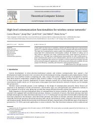
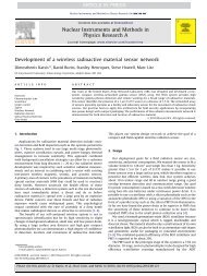
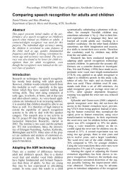
Fig. 1. The layout of our 2-D spectral disperser. The grat<strong>in</strong>g disperses <strong>in</strong> y; the VIPA disperses<br />
<strong>in</strong> x. OSA: optical spectrum analyzer <strong>with</strong> 0.01 nm resolution <strong>in</strong> <strong>wavelength</strong>. CYL: cyl<strong>in</strong>drical<br />
lens.<br />
Figure 1 shows our experimental setup. A solid VIPA <strong>with</strong> some glass of a refractive <strong>in</strong>dex<br />
nr~2 and a thickness t~1.5mm (FSR ~ 50 GHz) is used. The diffraction grat<strong>in</strong>g has a groove<br />
#4392 - $15.00 US Received 20 May 2004; revised 14 June 2004; accepted 15 June 2004<br />
(C) 2004 OSA 28 June 2004 / Vol. 12, No. 13 / OPTICS EXPRESS 2896<br />
f<br />
f
density of 1100 l<strong>in</strong>es/mm. The amplified spontaneous emission (ASE) source has a flat band<br />
~ 30 nm centered at 1.55 um. A collimated beam (<strong>in</strong>tensity falls to 1/e 2 at radius W=1.2 mm<br />
compared to the center) from the source is focused <strong>in</strong>to the VIPA by a cyl<strong>in</strong>drical lens <strong>with</strong><br />
focal length fc <strong>in</strong> the x dimension, and then the VIPA output (still collimated <strong>in</strong> y dimension)<br />
is diffracted by the diffraction grat<strong>in</strong>g <strong>in</strong> y dimension. The beam <strong>in</strong>cident angle θi <strong>in</strong>to the<br />
VIPA is ~ 4 o , and the beam <strong>in</strong>cident angle on the grat<strong>in</strong>g is θig ~ 70 o <strong>with</strong> a diffracted angle θd<br />
~ 50 o . A spherical lens (f =180 mm) focuses all beams onto the back focal plane, where a bare<br />
s<strong>in</strong>gle mode fiber (9/125 um) connected to an optical spectrum analyzer (OSA) samples the<br />
transmission spectra. The OSA has a spectral resolution of 0.01nm. The 2-D demultiplex<strong>in</strong>g<br />
can be understood <strong>in</strong> the follow<strong>in</strong>g way. First, assum<strong>in</strong>g no diffraction grat<strong>in</strong>g <strong>in</strong> the setup,<br />
the VIPA maps multiple peak <strong>wavelength</strong>s (multiple transmission peaks) <strong>with</strong> 50 GHz<br />
(0.4nm) period onto the same x position. If a diffraction grat<strong>in</strong>g is now used to disperse<br />
optical <strong>wavelength</strong>s <strong>in</strong> the y dimension, the multiple peak <strong>wavelength</strong>s <strong>with</strong> 50 GHz FSR<br />
separation at a s<strong>in</strong>gle x position will now separate to different y positions. Figure 2 shows a<br />
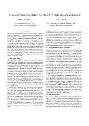
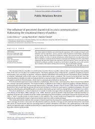
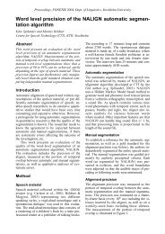
photograph of our 2-D <strong>wavelength</strong> <strong>demultiplexer</strong>. (Note that the beam expander shown <strong>in</strong> the<br />
photo is used only <strong>for</strong> our later experiment <strong>in</strong> connection <strong>with</strong> the data of Fig. 5.)<br />
We note that VIPAs are expected to have very low polarization dependent loss (PDL) [2].<br />
In pr<strong>in</strong>ciple, a low PDL grat<strong>in</strong>g can also be used <strong>in</strong> our setup, which means that a 2-D spectral<br />
disperser <strong>with</strong> low PDL is possible. In the present experiments, we do not use a low PDL<br />
grat<strong>in</strong>g, and there<strong>for</strong>e the 2-D spectral disperser works preferentially <strong>with</strong> y-polarized light.<br />
Cyl<strong>in</strong>drical<br />
Lens<br />
VIPA<br />
Beam<br />
Expander<br />
Collimator<br />
Grat<strong>in</strong>g<br />
Spherical<br />
Lens<br />
Bare Fiber<br />
Receiver<br />
Fig. 2. Photograph of our 2-D <strong>wavelength</strong> <strong>demultiplexer</strong>. (The beam expander shown <strong>in</strong> the<br />
photo is used only <strong>for</strong> our later experiment <strong>in</strong> connection <strong>with</strong> the data of Fig. 5.)<br />
#4392 - $15.00 US Received 20 May 2004; revised 14 June 2004; accepted 15 June 2004<br />
(C) 2004 OSA 28 June 2004 / Vol. 12, No. 13 / OPTICS EXPRESS 2897<br />
X<br />
Y
3. Theory<br />
Assum<strong>in</strong>g dispersion <strong>in</strong> x and dispersion <strong>in</strong> y are <strong>in</strong>dependent, the <strong>in</strong>tensity distribution<br />
dependence <strong>in</strong> space and <strong>wavelength</strong> is just the product of the distribution from the VIPA [9]<br />
and the distribution from the grat<strong>in</strong>g [6]<br />
( )<br />
( ⎥ ) ( ) ⎥ 2 ⎞<br />
⎤<br />
⎛ 2<br />
−<br />
~ 2<br />
⎡<br />
∝<br />
~ f c x<br />
1<br />
(<br />
⎟<br />
y<br />
⎜<br />
αω)<br />
I out x,<br />
y,<br />
λ<br />
−<br />
exp −<br />
⎜<br />
I <strong>in</strong> ( ω)<br />
⎢<br />
exp 2<br />
⎛<br />
2 2<br />
2<br />
f W ⎟<br />
2<br />
2<br />
⎦<br />
k ⎞ ⎢ ∆ w<br />
1 − ⎠<br />
⎝<br />
Rr<br />
⎣<br />
+ 4<br />
⎟ ⎜ Rr s<strong>in</strong><br />
0<br />
2 ⎠ ⎝<br />
(1)<br />
cos( θ ig )<br />
2<br />
fλ<br />
λ f<br />
where, w0<br />
= is the focused beam waist <strong>in</strong> y, α = is the<br />
cos( θ d ) πW<br />
2π<br />
cd cos( θ d )<br />
grat<strong>in</strong>g dispersion<br />
2<br />
tan<br />
parameter, ( )<br />
( θ<strong>in</strong><br />
) cos( θ i ) x cos(<br />
θ <strong>in</strong> ) x<br />
∆ = 2t<br />
nr<br />
cos θ<strong>in</strong> − 2t<br />
− t<br />
is the VIPA<br />
2<br />
f<br />
nr<br />
f<br />
dispersion parameter, )<br />
~<br />
I <strong>in</strong> (ω is the <strong>in</strong>put spectrum,<br />
~ ω = ω − ωo<br />
is the offset from the center<br />
ω 2π<br />
frequency, and k = = is the wave vector.<br />
c λ<br />
Equation (1) is the master equation that predicts the <strong>wavelength</strong> demultiplex<strong>in</strong>g<br />
characteristics <strong>in</strong> both space and spectrum dimensions as well as the demultiplex<strong>in</strong>g<br />
l<strong>in</strong>ewidth.<br />
The spatial dispersion of the VIPA disperser is [9]<br />
tan( θ ) cos( θ ) x 1 1 x<br />
λ (2)<br />
⎤<br />
⎡<br />
⎥<br />
⎢<br />
⎣<br />
⎦<br />
p − λ0<br />
= −λ0<br />
<strong>in</strong> i<br />
nr cos( θ <strong>in</strong> ) f<br />
+ 2<br />
2 nr<br />
2<br />
2<br />
f<br />
where, mλ 0 = 2tnr<br />
cos( θ <strong>in</strong> ) , θ <strong>in</strong> = θi<br />
nr<br />
is the beam angle <strong>in</strong>side the VIPA, and λp(x) is<br />
a <strong>wavelength</strong> whose <strong>in</strong>tensity distribution peaks at position x.<br />
The grat<strong>in</strong>g spatial dispersion is<br />
y − y0<br />
λ p − λ0<br />
= d cos( θ d )<br />
0 f<br />
(3)<br />
where, d s<strong>in</strong>( θ d ) + d s<strong>in</strong>( θ ) = λ<br />
0 ig 0 , and y0 is the spatial position of peak <strong>wavelength</strong> λ0.<br />
As the grat<strong>in</strong>g filter has a -3dB bandwidth of tens of GHz, which is an order of magnitude<br />
larger than that of the VIPA filter, the -3dB bandwidth is ma<strong>in</strong>ly determ<strong>in</strong>ed by the VIPA<br />
<strong>demultiplexer</strong> accord<strong>in</strong>g to master Eq. (1):<br />
c 1−<br />
Rr<br />
FWHM / frequency =<br />
,<br />
2π<br />
t n cos( θ ) Rr<br />
FWHM /<br />
<strong>wavelength</strong><br />
r<br />
λ0<br />
1−<br />
Rr<br />
=<br />
2π<br />
t n cos( θ ) Rr<br />
#4392 - $15.00 US Received 20 May 2004; revised 14 June 2004; accepted 15 June 2004<br />
(C) 2004 OSA 28 June 2004 / Vol. 12, No. 13 / OPTICS EXPRESS 2898<br />
r<br />
2<br />
i<br />
i<br />
(4)
4. Experiments<br />
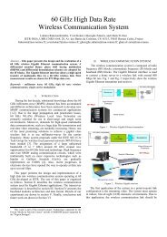
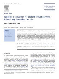
Fig 3. The 2-D <strong>wavelength</strong> demultiplex<strong>in</strong>g. Peak <strong>wavelength</strong>s are demultiplexed to different<br />
(x, y). The red solid l<strong>in</strong>es are approximate l<strong>in</strong>ear fitt<strong>in</strong>gs to the demultiplex<strong>in</strong>g data. The blue<br />
ellipses show the size at half maximum of the peak <strong>in</strong>tensity <strong>for</strong> two selected peak<br />
<strong>wavelength</strong>s.<br />
For the 2-D demultiplex<strong>in</strong>g, it is <strong>in</strong>terest<strong>in</strong>g to display the peak <strong>wavelength</strong>s correspond<strong>in</strong>g to<br />
various 2-D positions (x, y). In our test<strong>in</strong>g, we look at 41 peak <strong>wavelength</strong>s rang<strong>in</strong>g from<br />
1549.20 nm to 1550.80nm <strong>with</strong> a step of 0.04 nm (5GHz). Figure 3 shows the (x, y)<br />
correspond<strong>in</strong>g to all these chosen peak <strong>wavelength</strong>s. The x and y are read<strong>in</strong>gs from the<br />
micrometer <strong>with</strong> 0.01 mm resolution. The red solid l<strong>in</strong>es <strong>in</strong> the plot are approximate l<strong>in</strong>ear<br />
fitt<strong>in</strong>gs <strong>for</strong> the <strong>wavelength</strong> dispersion data, and it results from multiple diffraction orders of<br />
the VIPA. The beam <strong>in</strong>cident angle θi <strong>in</strong>to the VIPA is 4.2 o ± 0.2 o , which results <strong>in</strong> an<br />
approximate l<strong>in</strong>ear dispersion dom<strong>in</strong>ated by the first term on the right side <strong>in</strong> the Eq. (2). The<br />
blue ellipses <strong>in</strong> Fig. 3 show qualitatively the spatial <strong>in</strong>tensity distribution of two specific<br />
<strong>wavelength</strong>s, where the boundary <strong>in</strong>dicates positions <strong>with</strong> half maxima compared to the peak.<br />
The key po<strong>in</strong>t is that adjacent different orders of the VIPA are clearly separated <strong>in</strong> space.<br />
Experiments show 80 ± 10 um and 50 ± 10 um <strong>in</strong> diameter <strong>for</strong> the ellipse <strong>in</strong> both x and y<br />
direction, which agree well <strong>with</strong> our theory.<br />
#4392 - $15.00 US Received 20 May 2004; revised 14 June 2004; accepted 15 June 2004<br />
(C) 2004 OSA 28 June 2004 / Vol. 12, No. 13 / OPTICS EXPRESS 2899
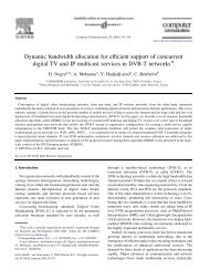
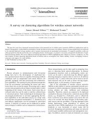
Fig. 4. (a) is the 2-D multiple demultiplex<strong>in</strong>g <strong>channels</strong> <strong>with</strong> center channel <strong>wavelength</strong>s<br />
correspond<strong>in</strong>g to the data <strong>in</strong> Fig. 3, and (b) is the correspond<strong>in</strong>g channel l<strong>in</strong>eshape.<br />
Figure 4(a) shows the l<strong>in</strong>eshapes of the 41 2-D demultiplex<strong>in</strong>g <strong>channels</strong>, correspond<strong>in</strong>g to<br />
the spatial positions <strong>in</strong> Fig. 3. Experimentally, we show a channel spac<strong>in</strong>g 5GHz (0.04 nm), a<br />
channel -3dB bandwidth of 1.75 GHz and good channel isolations > 20dB. The periodic<br />
<strong>in</strong>tensity modulation at the VIPA’s FSR (0.4 nm) results from transitions between dom<strong>in</strong>ant<br />
VIPA diffraction orders together <strong>with</strong> the Gaussian roll-off of the envelope as a function of x,<br />
which is fully modeled by our master equation (1). Note that the 1.6 nm band tested <strong>in</strong> Fig.<br />
4(a) was chosen solely <strong>for</strong> experimental convenience. In pr<strong>in</strong>ciple, our scheme should extend<br />
equally over a very wide band. Thus, we demonstrate a new scheme <strong>with</strong> <strong>potential</strong> <strong>for</strong> ≥ <strong>1000</strong><br />
hyperf<strong>in</strong>e <strong>channels</strong> us<strong>in</strong>g the 2-D <strong>demultiplexer</strong> based on the VIPA and the diffraction grat<strong>in</strong>g<br />
<strong>in</strong> bulk optics.<br />
#4392 - $15.00 US Received 20 May 2004; revised 14 June 2004; accepted 15 June 2004<br />
(C) 2004 OSA 28 June 2004 / Vol. 12, No. 13 / OPTICS EXPRESS 2900<br />
(a)<br />
(b)
Figure 4(b) shows the normalized l<strong>in</strong>eshape <strong>for</strong> one of those <strong>channels</strong> <strong>in</strong> greater detail.<br />
The blue dashed one is the grat<strong>in</strong>g filter’s Gaussian l<strong>in</strong>eshape <strong>with</strong>out <strong>in</strong>sert<strong>in</strong>g the VIPA, and<br />
the red solid curve is the l<strong>in</strong>eshape of the 2-D <strong>demultiplexer</strong>. The right side lobe on the 2-D<br />
<strong>demultiplexer</strong>’s l<strong>in</strong>eshape is a small residue aris<strong>in</strong>g from the 50 GHz FSR of the VIPA; the<br />
side lobe is suppressed down to -25 dB compared to the peak level of the grat<strong>in</strong>g filter alone.<br />
The lack of complete suppression is attributed to the fact that the limited aperture of our VIPA<br />
<strong>in</strong> the y direction slightly clips the <strong>in</strong>put beam to the grat<strong>in</strong>g, which slightly distorts the<br />
grat<strong>in</strong>g filter l<strong>in</strong>eshape. The observed -3dB band<strong>with</strong> of 1.75 GHz (14 pm) is largely<br />
determ<strong>in</strong>ed by the VIPA filter. In addition, by tak<strong>in</strong>g <strong>in</strong>to account the f<strong>in</strong>ite spectral resolution<br />
of the OSA (10 pm), we estimate that the actual l<strong>in</strong>eshape has ~ 1.25 GHz (10 pm) -3dB<br />
bandwidth [3, 4], which allows a smaller channel spac<strong>in</strong>g.<br />
Fig. 5. (a) is another sample of the demultiplex<strong>in</strong>g channel response <strong>with</strong> improved <strong>in</strong>sertion<br />
loss per<strong>for</strong>mance and same spatial dispersion compared to Fig. 4, and (b) is the correspond<strong>in</strong>g<br />
channel l<strong>in</strong>eshape.<br />
#4392 - $15.00 US Received 20 May 2004; revised 14 June 2004; accepted 15 June 2004<br />
(C) 2004 OSA 28 June 2004 / Vol. 12, No. 13 / OPTICS EXPRESS 2901
For practical 2-D hyperf<strong>in</strong>e WDM systems, the <strong>in</strong>sertion loss <strong>for</strong> the peak <strong>wavelength</strong> is<br />
also an important per<strong>for</strong>mance parameter. In our experiments above, the <strong>in</strong>sertion loss <strong>for</strong> the<br />
2-D demultipexer is not optimized due to the relatively large focus<strong>in</strong>g spot size (~ 80 um <strong>in</strong> x<br />
and ~ 50 um <strong>in</strong> y). In addition, it is desirable to further suppress the residual side lobes due to<br />
the VIPA’s FSR (Fig. 4(b)) <strong>for</strong> even lower channel crosstalk. A feasible way to optimize both<br />
the <strong>in</strong>sertion loss per<strong>for</strong>mance and side lobe suppression is to use collimated beams <strong>with</strong><br />
larger radius W, which would result <strong>in</strong> smaller focused spot size <strong>in</strong> y <strong>for</strong> the grat<strong>in</strong>g and also<br />
narrower bandwidth <strong>for</strong> the grat<strong>in</strong>g filter. Currently, we are limited by the VIPA aperture size<br />
<strong>in</strong> y. Instead of us<strong>in</strong>g a collimator <strong>with</strong> larger beam radius, it is possible to do this <strong>with</strong> a beam<br />
expander <strong>in</strong> y only between the VIPA and the grat<strong>in</strong>g. There<strong>for</strong>e, <strong>in</strong> another experiment, we<br />
<strong>in</strong>serted a beam expander (4×) work<strong>in</strong>g <strong>in</strong> y based on two cyl<strong>in</strong>drical lenses between the<br />
VIPA and the grat<strong>in</strong>g (Fig. 2.). All other experimental conditions were left unchanged. The<br />
channel response is ma<strong>in</strong>ta<strong>in</strong>ed while the side lobes are suppressed to lower than 30dB down<br />
compared to the peak level (Fig. 5). The 2-D dispersion relationship is the same as <strong>in</strong> Fig. 3;<br />
the beam expander doesn’t change the dispersion relation. For simplicity, we have plotted<br />
only a group of 11 <strong>channels</strong> <strong>in</strong> a 0.4 nm range <strong>in</strong> Fig. 5(a); however, as <strong>in</strong>dicated <strong>in</strong> Fig. 4(a),<br />
it is possible to extend over the entire C-band. The total <strong>in</strong>sertion loss is ~ 17 dB <strong>for</strong> ypolarized<br />
light, and the total <strong>in</strong>sertion loss is 4 - 5 dB less than the first setup. Lower <strong>in</strong>sertion<br />
loss should be possible us<strong>in</strong>g a beam expander <strong>with</strong> larger expand<strong>in</strong>g factor <strong>for</strong> close modematched<br />
coupl<strong>in</strong>g <strong>in</strong>to the s<strong>in</strong>gle mode fiber. The ripples on the w<strong>in</strong>gs of the grat<strong>in</strong>g filter<br />
l<strong>in</strong>eshape are due to small beam clipp<strong>in</strong>gs both at the grat<strong>in</strong>g edge and at the VIPA <strong>in</strong> y<br />
accord<strong>in</strong>g to our experiments. In pr<strong>in</strong>ciple, the <strong>in</strong>sertion loss per<strong>for</strong>mance could be optimized<br />
further by tighter focus<strong>in</strong>g <strong>in</strong> x. One approach <strong>for</strong> achiev<strong>in</strong>g this would be to <strong>in</strong>corporate<br />
<strong>in</strong>dependent cyl<strong>in</strong>drical focus<strong>in</strong>g <strong>in</strong> x and y between the grat<strong>in</strong>g and the receiv<strong>in</strong>g fiber. In<br />
pr<strong>in</strong>ciple, we may have a very low <strong>in</strong>sertion loss assum<strong>in</strong>g we obta<strong>in</strong> mode-matched coupl<strong>in</strong>g<br />
<strong>in</strong> both x and y <strong>for</strong> the s<strong>in</strong>gle mode fiber receiver while ma<strong>in</strong>ta<strong>in</strong><strong>in</strong>g the channel response.<br />
5. Conclusion<br />
In summary, we demonstrate a 2-D <strong>wavelength</strong> <strong>demultiplexer</strong> <strong>with</strong> a narrow -3dB bandwidth<br />
of 1.75 GHz determ<strong>in</strong>ed by the VIPA filter and a very large FSR determ<strong>in</strong>ed by the<br />
diffraction grat<strong>in</strong>g. We present a simple analytic theory <strong>for</strong> the 2-D <strong>wavelength</strong> <strong>demultiplexer</strong>.<br />
Experimentally, we show demultiplex<strong>in</strong>g <strong>channels</strong> <strong>with</strong> a spac<strong>in</strong>g of 5 GHz and good channel<br />
isolations > 20dB, which has the <strong>potential</strong> to allow hyperf<strong>in</strong>e WDM <strong>with</strong> channel ≥ number<br />
<strong>1000</strong> <strong>in</strong> the C-band. We also show the possibility of <strong>in</strong>creas<strong>in</strong>g the side lobe suppression to ><br />
30 dB. In future work, we are <strong>in</strong>terested <strong>in</strong> <strong>in</strong>vestigat<strong>in</strong>g 2-D waveguide-fiber arrays <strong>for</strong><br />
output coupl<strong>in</strong>g as well as reflective Fourier trans<strong>for</strong>m pulse shap<strong>in</strong>g [6, 7] us<strong>in</strong>g the 2-D<br />
<strong>wavelength</strong> <strong>demultiplexer</strong>, where it may be easier to realize low <strong>in</strong>sertion loss.<br />
Acknowledgments<br />
We gratefully acknowledge Christopher L<strong>in</strong> from the Avanex Corporation <strong>for</strong> provid<strong>in</strong>g the<br />
VIPA samples. This work is supported <strong>in</strong> part by the ARO under grant number DAAD19-03-<br />
1-0275 and by the NSF under grant number 0100949-ECS.<br />
#4392 - $15.00 US Received 20 May 2004; revised 14 June 2004; accepted 15 June 2004<br />
(C) 2004 OSA 28 June 2004 / Vol. 12, No. 13 / OPTICS EXPRESS 2902