Installation Guide ECL Comfort 310, application A376 - Danfoss.com
Installation Guide ECL Comfort 310, application A376 - Danfoss.com
Installation Guide ECL Comfort 310, application A376 - Danfoss.com

Create successful ePaper yourself
Turn your PDF publications into a flip-book with our unique Google optimized e-Paper software.
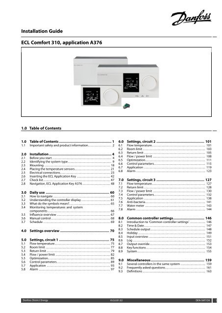
<strong>Installation</strong> <strong>Guide</strong><br />
<strong>ECL</strong> <strong>Comfort</strong> <strong>310</strong>, <strong>application</strong> <strong>A376</strong><br />
1.0 Table of Contents<br />
1.0 Table of Contents ............................................... 1<br />
1.1 Important safety and product information. . . . . . . . . . . . . . . . . . . . . 2<br />
2.0 <strong>Installation</strong> ........................................................ 4<br />
2.1 Before you start . . . . . . . . . . . . . . . . . . . . . . . . . . . . . . . . . . . . . . . . . . . . . . . . . . . . . 4<br />
2.2 Identifying the system type....................................... 9<br />
2.3 Mounting . . . . . . . . . . . . . . . . . . . . . . . . . . . . . . . . . . . . . . . . . . . . . . . . . . . . . . . . . . . 18<br />
2.4 Placing the temperature sensors. . . . . . . . . . . . . . . . . . . . . . . . . . . . . . . . 21<br />
2.5 Electrical connections. . . . . . . . . . . . . . . . . . . . . . . . . . . . . . . . . . . . . . . . . . . . . 23<br />
2.6 Inserting the <strong>ECL</strong> Application Key . . . . . . . . . . . . . . . . . . . . . . . . . . . . . . 42<br />
2.7 Check list . . . . . . . . . . . . . . . . . . . . . . . . . . . . . . . . . . . . . . . . . . . . . . . . . . . . . . . . . . . . 47<br />
2.8 Navigation, <strong>ECL</strong> Application Key <strong>A376</strong> . . . . . . . . . . . . . . . . . . . . . . . . . 48<br />
3.0 Daily use ......................................................... 60<br />
3.1 How to navigate . . . . . . . . . . . . . . . . . . . . . . . . . . . . . . . . . . . . . . . . . . . . . . . . . . . 60<br />
3.2 Understanding the controller display . . . . . . . . . . . . . . . . . . . . . . . . . . 61<br />
3.3 What do the symbols mean?. . . . . . . . . . . . . . . . . . . . . . . . . . . . . . . . . . . . . 65<br />
3.4 Monitoring temperatures and system<br />
<strong>com</strong>ponents . . . . . . . . . . . . . . . . . . . . . . . . . . . . . . . . . . . . . . . . . . . . . . . . . . . . . . . . 66<br />
3.5 Influence overview . . . . . . . . . . . . . . . . . . . . . . . . . . . . . . . . . . . . . . . . . . . . . . . . 67<br />
3.6 Manual control . . . . . . . . . . . . . . . . . . . . . . . . . . . . . . . . . . . . . . . . . . . . . . . . . . . . . 68<br />
3.7 Schedule . . . . . . . . . . . . . . . . . . . . . . . . . . . . . . . . . . . . . . . . . . . . . . . . . . . . . . . . . . . . 69<br />
4.0 Settings overview ............................................ 70<br />
5.0 Settings, circuit 1 ............................................. 75<br />
5.1 Flow temperature. . . . . . . . . . . . . . . . . . . . . . . . . . . . . . . . . . . . . . . . . . . . . . . . . . 75<br />
5.2 Room limit . . . . . . . . . . . . . . . . . . . . . . . . . . . . . . . . . . . . . . . . . . . . . . . . . . . . . . . . . . 77<br />
5.3 Return limit . . . . . . . . . . . . . . . . . . . . . . . . . . . . . . . . . . . . . . . . . . . . . . . . . . . . . . . . . 79<br />
5.4 Flow / power limit . . . . . . . . . . . . . . . . . . . . . . . . . . . . . . . . . . . . . . . . . . . . . . . . . 82<br />
5.5 Optimization. . . . . . . . . . . . . . . . . . . . . . . . . . . . . . . . . . . . . . . . . . . . . . . . . . . . . . . . 85<br />
5.6 Control parameters. . . . . . . . . . . . . . . . . . . . . . . . . . . . . . . . . . . . . . . . . . . . . . . . 89<br />
5.7 Application . . . . . . . . . . . . . . . . . . . . . . . . . . . . . . . . . . . . . . . . . . . . . . . . . . . . . . . . . 93<br />
5.8 Alarm . . . . . . . . . . . . . . . . . . . . . . . . . . . . . . . . . . . . . . . . . . . . . . . . . . . . . . . . . . . . . . . . 97<br />
6.0 Settings, circuit 2 ........................................... 101<br />
6.1 Flow temperature. . . . . . . . . . . . . . . . . . . . . . . . . . . . . . . . . . . . . . . . . . . . . . . . 101<br />
6.2 Room limit . . . . . . . . . . . . . . . . . . . . . . . . . . . . . . . . . . . . . . . . . . . . . . . . . . . . . . . . 103<br />
6.3 Return limit . . . . . . . . . . . . . . . . . . . . . . . . . . . . . . . . . . . . . . . . . . . . . . . . . . . . . . . 105<br />
6.4 Flow / power limit . . . . . . . . . . . . . . . . . . . . . . . . . . . . . . . . . . . . . . . . . . . . . . . 108<br />
6.5 Optimization. . . . . . . . . . . . . . . . . . . . . . . . . . . . . . . . . . . . . . . . . . . . . . . . . . . . . . 111<br />
6.6 Control parameters. . . . . . . . . . . . . . . . . . . . . . . . . . . . . . . . . . . . . . . . . . . . . . 115<br />
6.7 Application . . . . . . . . . . . . . . . . . . . . . . . . . . . . . . . . . . . . . . . . . . . . . . . . . . . . . . . 119<br />
6.8 Alarm . . . . . . . . . . . . . . . . . . . . . . . . . . . . . . . . . . . . . . . . . . . . . . . . . . . . . . . . . . . . . . 123<br />
7.0 Settings, circuit 3 ........................................... 127<br />
7.1 Flow temperature. . . . . . . . . . . . . . . . . . . . . . . . . . . . . . . . . . . . . . . . . . . . . . . . 127<br />
7.2 Return limit . . . . . . . . . . . . . . . . . . . . . . . . . . . . . . . . . . . . . . . . . . . . . . . . . . . . . . . 128<br />
7.3 Flow / power limit . . . . . . . . . . . . . . . . . . . . . . . . . . . . . . . . . . . . . . . . . . . . . . . 130<br />
7.4 Control parameters. . . . . . . . . . . . . . . . . . . . . . . . . . . . . . . . . . . . . . . . . . . . . . 132<br />
7.5 Application . . . . . . . . . . . . . . . . . . . . . . . . . . . . . . . . . . . . . . . . . . . . . . . . . . . . . . . 138<br />
7.6 Anti-bacteria. . . . . . . . . . . . . . . . . . . . . . . . . . . . . . . . . . . . . . . . . . . . . . . . . . . . . . 141<br />
7.7 Water meter . . . . . . . . . . . . . . . . . . . . . . . . . . . . . . . . . . . . . . . . . . . . . . . . . . . . . . 143<br />
7.8 Alarm . . . . . . . . . . . . . . . . . . . . . . . . . . . . . . . . . . . . . . . . . . . . . . . . . . . . . . . . . . . . . . 144<br />
8.0 Common controller settings............................ 146<br />
8.1 Introduction to ‘Common controller settings’ . . . . . . . . . . . . . . 146<br />
8.2 Time & Date. . . . . . . . . . . . . . . . . . . . . . . . . . . . . . . . . . . . . . . . . . . . . . . . . . . . . . . 147<br />
8.3 Schedule output . . . . . . . . . . . . . . . . . . . . . . . . . . . . . . . . . . . . . . . . . . . . . . . . . 148<br />
8.4 Holiday . . . . . . . . . . . . . . . . . . . . . . . . . . . . . . . . . . . . . . . . . . . . . . . . . . . . . . . . . . . . 149<br />
8.5 Input overview . . . . . . . . . . . . . . . . . . . . . . . . . . . . . . . . . . . . . . . . . . . . . . . . . . . 151<br />
8.6 Log . . . . . . . . . . . . . . . . . . . . . . . . . . . . . . . . . . . . . . . . . . . . . . . . . . . . . . . . . . . . . . . . . 152<br />
8.7 Output override. . . . . . . . . . . . . . . . . . . . . . . . . . . . . . . . . . . . . . . . . . . . . . . . . . 153<br />
8.8 Key functions . . . . . . . . . . . . . . . . . . . . . . . . . . . . . . . . . . . . . . . . . . . . . . . . . . . . . 154<br />
8.9 System . . . . . . . . . . . . . . . . . . . . . . . . . . . . . . . . . . . . . . . . . . . . . . . . . . . . . . . . . . . . . 155<br />
9.0 Miscellaneous................................................ 159<br />
9.1 Several controllers in the same system . . . . . . . . . . . . . . . . . . . . . . 159<br />
9.2 Frequently asked questions. . . . . . . . . . . . . . . . . . . . . . . . . . . . . . . . . . . . 161<br />
9.3 Definitions . . . . . . . . . . . . . . . . . . . . . . . . . . . . . . . . . . . . . . . . . . . . . . . . . . . . . . . . 163<br />
<strong>Danfoss</strong> District Energy VI.GU.B1.02 DEN-SMT/DK 1
<strong>Installation</strong> <strong>Guide</strong> <strong>ECL</strong> <strong>Comfort</strong> <strong>310</strong>, <strong>application</strong> <strong>A376</strong><br />
1.1 Important safety and product information<br />
1.1.1 Important safety and product information<br />
This <strong>Installation</strong> <strong>Guide</strong> is associated with <strong>ECL</strong> Application Key <strong>A376</strong><br />
(order code no. 087H3810).<br />
The functions can be realized in <strong>ECL</strong> <strong>Comfort</strong> <strong>310</strong> which includes<br />
M-bus, Modbus and Ethernet (Internet) <strong>com</strong>munication.<br />
The <strong>application</strong>s <strong>A376</strong>.1/ <strong>A376</strong>.2 / <strong>A376</strong>.3 / <strong>A376</strong>.9 <strong>com</strong>ply with<br />
<strong>ECL</strong> <strong>Comfort</strong> controller <strong>310</strong> as of software version 1.11 (visible at<br />
start-up of the controller and in ‘Common controller settings’ in<br />
‘System’).<br />
Additional documentation for <strong>ECL</strong> <strong>Comfort</strong> <strong>310</strong>, modules and<br />
accessories is available on http://den.danfoss.<strong>com</strong>/.<br />
Automatic update of controller software:<br />
The software of the controller is updated automatically when the key<br />
is inserted (as of controller version 1.11). The following animation will<br />
be shown when the software is being updated:<br />
Progress bar<br />
Safety Note<br />
To avoid injury of persons and damages to the device, it is absolutely<br />
necessary to read and observe these instructions carefully.<br />
Necessary assembly, start-up, and maintenance work must be<br />
performed by qualified and authorized personnel only.<br />
The warning sign is used to emphasize special conditions that should<br />
be taken into consideration.<br />
This symbol indicates that this particular piece of information should<br />
be read with special attention.<br />
As this <strong>Installation</strong> <strong>Guide</strong> covers several system types, special system<br />
settings will be marked with a system type. All system types are shown<br />
in the chapter: 'Identifying your system type'.<br />
2 DEN-SMT/DK VI.GU.B1.02 <strong>Danfoss</strong> District Energy
<strong>Installation</strong> <strong>Guide</strong> <strong>ECL</strong> <strong>Comfort</strong> <strong>310</strong>, <strong>application</strong> <strong>A376</strong><br />
°C (degrees Celsius) is a measured temperature value whereas K<br />
(Kelvin) is a number of degrees.<br />
The ID no. is unique for the selected parameter.<br />
Example First digit Second digit Last three digits<br />
11174 1 1 174<br />
- Circuit 1 Parameter no.<br />
12174 1 2 174<br />
- Circuit 2 Parameter no.<br />
If an ID description is mentioned more than once, it means that there<br />
are special settings for one or more system types. It will be marked<br />
with the system type in question (e.g. 12174 - A266.9).<br />
Disposal Note<br />
This product should be dismantled and its <strong>com</strong>ponents<br />
sorted, if possible, in various groups before recycling<br />
or disposal.<br />
Always follow the local disposal regulations.<br />
<strong>Danfoss</strong> District Energy VI.GU.B1.02 DEN-SMT/DK 3
<strong>Installation</strong> <strong>Guide</strong> <strong>ECL</strong> <strong>Comfort</strong> <strong>310</strong>, <strong>application</strong> <strong>A376</strong><br />
2.0 <strong>Installation</strong><br />
2.1 Before you start<br />
The <strong>application</strong>s, <strong>A376</strong>.1, <strong>A376</strong>.2, <strong>A376</strong>.3 and <strong>A376</strong>.9 are almost<br />
identical. However, some <strong>application</strong>s have extra functions which<br />
are described separately.<br />
The <strong>application</strong>s are very flexible. These are the basic principles:<br />
Heating (circuit 1):<br />
Typically, the flow temperature is adjusted according to your<br />
requirements. The flow temperature sensor S3 is the most<br />
important sensor. The desired flow temperature at S3 is calculated<br />
in the <strong>ECL</strong> controller, based on the outdoor temperature (S1).<br />
The lower the outdoor temperature, the higher the desired flow<br />
temperature. By means of a week schedule (up to 3 ‘<strong>Comfort</strong>’<br />
periods / day), the heating circuit 1 can be in ‘<strong>Comfort</strong>’ or<br />
‘Saving’ mode (two different temperature values for desired room<br />
temperature).<br />
The motorized control valve M2 is opened gradually when the<br />
flow temperature is lower than the desired flow temperature and<br />
vice versa.<br />
The return temperature (S5) to the district heating supply should<br />
not be too high. If so, the desired flow temperature can be adjusted<br />
(typically to a lower value), thus resulting in a gradual closing of the<br />
motorized control valve.<br />
In boiler-based heating supply the return temperature should not<br />
be too low (same adjustment procedure as above).<br />
Furthermore, the return temperature limitation can depend<br />
on the outdoor temperature. Typically, the lower the outdoor<br />
temperature, the higher the accepted return temperature.<br />
The circulation pump (P2) is ON at heat demand or at frost<br />
protection.<br />
The heating can be switched OFF when the outdoor temperature is<br />
higher than a selectable value.<br />
<strong>A376</strong>.1, <strong>A376</strong>.2 and <strong>A376</strong>.3:<br />
If the measured room temperature does not equal the desired<br />
room temperature, the desired flow temperature can be adjusted.<br />
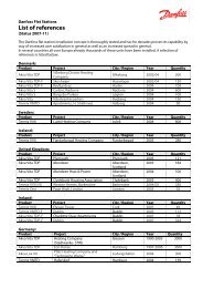
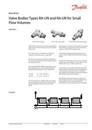
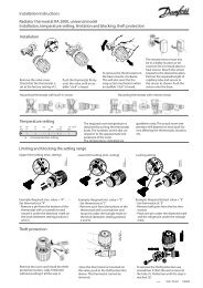
Typical <strong>A376</strong> <strong>application</strong>:<br />
S1<br />
M2<br />
M3<br />
M1<br />
S5<br />
S10<br />
S6<br />
S3<br />
S9<br />
S4<br />
<strong>ECL</strong> <strong>310</strong><br />
P2<br />
P3<br />
The shown diagram is a fundamental and simplified example and<br />
does not contain all <strong>com</strong>ponents that are necessary in a system. The<br />
numbers in circles refer to the circuit numbers.<br />
All named <strong>com</strong>ponents are connected to the <strong>ECL</strong> <strong>Comfort</strong> controller.<br />
List of <strong>com</strong>ponents: <strong>A376</strong> in general, sensors<br />
S1 Outdoor temperature sensor<br />
S2 Room temperature sensor, circuit 1 (<strong>A376</strong>.2: Room<br />
temperature sensor, circuits 1 and 2)<br />
S3 Flow temperature sensor, circuit 1<br />
S4 DHW temperature sensor, circuit 3<br />
S5 Return temperature sensor, circuit 1<br />
S6 Return temperature sensor, circuit 3<br />
S7 Room temperature sensor, circuit 2 / (<strong>A376</strong>.2: Supply<br />
temperature sensor) / (<strong>A376</strong>.9: Pressure signal input)<br />
(S8) (<strong>A376</strong>.2: Flow switch) / (<strong>A376</strong>.9: Alarm input)<br />
S9 Flow temperature sensor, circuit 2<br />
S10 Return temperature sensor, circuit 2<br />
(S11) (<strong>A376</strong>.9: Supply flow temperature sensor)<br />
(S12) (<strong>A376</strong>.9: Supply return temperature sensor)<br />
(S13) (<strong>A376</strong>.9: Return temperature sensor, circuit 2)<br />
(S14) (<strong>A376</strong>.9: Pressure signal input)<br />
(S15) (<strong>A376</strong>.9: Alarm input)<br />
(S16) (<strong>A376</strong>.9: Alarm input)<br />
4 DEN-SMT/DK VI.GU.B1.02 <strong>Danfoss</strong> District Energy<br />
R6<br />
P1<br />
S2<br />
S7<br />
①<br />
②<br />
③<br />
<strong>Danfoss</strong><br />
87H2097.10
<strong>Installation</strong> <strong>Guide</strong> <strong>ECL</strong> <strong>Comfort</strong> <strong>310</strong>, <strong>application</strong> <strong>A376</strong><br />
Heating (circuit 2):<br />
This circuit works after same principles as circuit 1.<br />
The flow temperature sensor S9 is the most important sensor.<br />
By means of a week schedule (up to 3 ‘<strong>Comfort</strong>’ periods / day),<br />
heating circuit 2 can be in ‘<strong>Comfort</strong>’ or ‘Saving’ mode (two different<br />
temperature values for desired room temperature). The motorized<br />
control valve M3 controls the circuit.<br />
The return temperature (S10) enables limitation as described<br />
previously.<br />
The circulation pump (P3) is ON at heat demand or at frost<br />
protection.<br />
The heating can be switched OFF when the outdoor temperature is<br />
higher than a selectable value.<br />
Heating circuit 2 can be connected after heating circuit 1. If so, the<br />
desired flow temperature at S3 can be influenced by the desired<br />
flow temperature at S9.<br />
<strong>A376</strong>.1, <strong>A376</strong>.2 and <strong>A376</strong>.3:<br />
If the measured room temperature does not equal the desired<br />
room temperature, the desired flow temperature can be adjusted.<br />
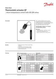
List of <strong>com</strong>ponents: <strong>A376</strong> in general, pumps and actuators<br />
P1 DHW circulation pump, circuit 3<br />
P2 Heating circulation pump, circuit 1<br />
P3 Heating circulation pump, circuit 2<br />
M1 Motorized control valve, circuit 3<br />
M2 Motorized control valve, circuit 1<br />
M3 Motorized control valve, circuit 2<br />
(R4) (<strong>A376</strong>.9: Relay output, alarm)<br />
R6 Relay output, alarm<br />
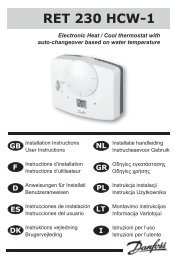
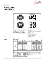
<strong>A376</strong>.1 example a:<br />
S1<br />
M2<br />
M3<br />
M1<br />
<strong>A376</strong>.1 example b:<br />
<strong>Danfoss</strong> District Energy VI.GU.B1.02 DEN-SMT/DK 5<br />
S1<br />
M2<br />
S5<br />
M1<br />
S6<br />
S5<br />
S10<br />
S6<br />
S3<br />
S4<br />
S3<br />
S9<br />
S4<br />
<strong>ECL</strong> <strong>310</strong><br />
P2<br />
P3<br />
<strong>ECL</strong> <strong>310</strong><br />
M3<br />
S9<br />
S10<br />
R6<br />
R6<br />
P2<br />
P3<br />
P1<br />
P1<br />
S2<br />
S7<br />
S2<br />
S7<br />
①<br />
②<br />
③<br />
①<br />
②<br />
③<br />
<strong>Danfoss</strong><br />
87H2097.10<br />
<strong>Danfoss</strong><br />
87H2098.10
<strong>Installation</strong> <strong>Guide</strong> <strong>ECL</strong> <strong>Comfort</strong> <strong>310</strong>, <strong>application</strong> <strong>A376</strong><br />
Domestic Hot Water (DHW, circuit 3):<br />
If the measured DHW temperature (S4) is lower than the desired<br />
DHW temperature, the motorized control valve (M1) is opened<br />
gradually and vice versa.<br />
By means of a week schedule (up to 3 <strong>Comfort</strong> periods / day), the<br />
DHW circuit can be in ‘<strong>Comfort</strong>’ or ‘Saving’ mode (two different<br />
temperature values for desired DHW temperature).<br />
If the desired DHW temperature cannot be reached, the heating<br />
circuits can be closed gradually to allow more energy to the DHW<br />
circuit.<br />
An anti-bacteria function is available for activation on selected<br />
days of the week.<br />
A 376.1, <strong>A376</strong>.2 and <strong>A376</strong>.3:<br />
The return tempeature (S6) can be limited to a fixed value.<br />
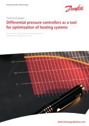
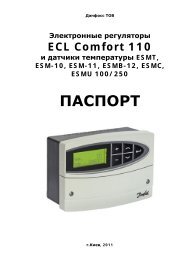
<strong>A376</strong>.2, DHW circuit, extra functions:<br />
The DHW circuit can operate with or without DHW circulation. The<br />
DHW temperature at S4 is maintained at ‘<strong>Comfort</strong>’ level when a<br />
DHW tapping is ongoing (the flow switch (S8) is activated).<br />
In order to <strong>com</strong>pensate for the reaction time, the motorized control<br />
valve can be pre-activated at the start of a DHW tapping.<br />
An idle temperature can be maintained at either S6 or S4 when<br />
there is no DHW tapping.<br />
<strong>A376</strong>.2 example a:<br />
S1<br />
S7<br />
M2<br />
M3<br />
M1<br />
<strong>A376</strong>.2 example b:<br />
S7<br />
S1<br />
M2<br />
S5<br />
M1<br />
S6<br />
<strong>A376</strong>.3 example a:<br />
6 DEN-SMT/DK VI.GU.B1.02 <strong>Danfoss</strong> District Energy<br />
S1<br />
A<br />
A<br />
A<br />
M2<br />
M3<br />
M1<br />
S5<br />
S10<br />
S6<br />
S5<br />
S10<br />
S6<br />
S3<br />
S4<br />
S3<br />
S9<br />
S4<br />
S3<br />
S9<br />
S4<br />
S8<br />
<strong>ECL</strong> <strong>310</strong><br />
P2<br />
P3<br />
S8<br />
<strong>ECL</strong> <strong>310</strong><br />
M3<br />
<strong>ECL</strong> <strong>310</strong><br />
+ ECA 32<br />
P2<br />
P3<br />
S9<br />
S10<br />
R6<br />
R6<br />
R6<br />
P1<br />
P2<br />
P3<br />
P1<br />
P1<br />
(S2)<br />
(S2)<br />
S2<br />
S7<br />
①<br />
②<br />
③<br />
(S2)<br />
(S2)<br />
①<br />
②<br />
③<br />
<strong>Danfoss</strong><br />
87H2101.10<br />
<strong>Danfoss</strong><br />
87H2099.10<br />
①<br />
②<br />
③<br />
<strong>Danfoss</strong><br />
87H2100.10
<strong>Installation</strong> <strong>Guide</strong> <strong>ECL</strong> <strong>Comfort</strong> <strong>310</strong>, <strong>application</strong> <strong>A376</strong><br />
Application <strong>A376</strong>.3 in general:<br />
The <strong>application</strong> is similar to the <strong>A376</strong>.1 <strong>application</strong> but the<br />
motorized control valves are controlled by means of 0-10 volt<br />
signals (analog signals). The triac outputs are not active for<br />
activating 3-point controlled actuators. The <strong>application</strong> A 376.3<br />
requires the internal I/O module ECA 32 in order to activate 0-10<br />
volt controlled actuators.<br />
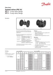
Application <strong>A376</strong>.9 in general:<br />
The <strong>application</strong> is similar to the <strong>A376</strong>.1 but with special functions.<br />
The <strong>application</strong> <strong>A376</strong>.9 requires the internal I/O module ECA 32 in<br />
order to receive signals from the inputs S11 - S16.<br />
Heating circuits 1 and 2:<br />
• There are no room temperature influence possibilities.<br />
• The secondary return temperatures (S2 and S10) are used for<br />
monitoring only.<br />
• The pressure measurings, 0-10 volt (S7 and S14,) are used to<br />
activate an alarm if the actual pressure is higher or lower than<br />
the chosen settings.<br />
DHW circuit 3:<br />
• The secondary return temperature (S6) is used for monitoring<br />
only.<br />
All circuits:<br />
• The temperatures (S11 and S12) are used for monitoring only.<br />
• The switch inputs (S8, S15 and S16) are related to the circuits<br />
1, 2 and 3 respectively. Typically used as alarm signal for<br />
malfunction of the circulation pump in question.<br />
<strong>A376</strong>.3 example b:<br />
<strong>A376</strong>.9 example a:<br />
S1<br />
S11<br />
S12<br />
<strong>A376</strong>.9 example b:<br />
S1<br />
M2<br />
M3<br />
M1<br />
M2<br />
S5<br />
M1<br />
S5<br />
S13<br />
S3<br />
S4<br />
S6<br />
S3<br />
S9<br />
S4<br />
<strong>ECL</strong> <strong>310</strong><br />
+ ECA 32<br />
S2<br />
S10<br />
S6<br />
<strong>ECL</strong> <strong>310</strong><br />
+ ECA 32<br />
S7<br />
S14<br />
M3<br />
R4<br />
P2<br />
P3<br />
R4<br />
S10<br />
S9<br />
P2<br />
P3<br />
P1<br />
S8 S15 S16<br />
P1<br />
S8 S15 S16<br />
<strong>Danfoss</strong> District Energy VI.GU.B1.02 DEN-SMT/DK 7<br />
S11<br />
S12<br />
S2<br />
S7<br />
S14<br />
①<br />
②<br />
③<br />
①<br />
②<br />
③<br />
<strong>Danfoss</strong><br />
87H2103.10<br />
①<br />
②<br />
③<br />
<strong>Danfoss</strong><br />
87H2104.10
<strong>Installation</strong> <strong>Guide</strong> <strong>ECL</strong> <strong>Comfort</strong> <strong>310</strong>, <strong>application</strong> <strong>A376</strong><br />
The controller is pre-programmed with factory settings that are shown<br />
in the relevant chapters of this guide.<br />
8 DEN-SMT/DK VI.GU.B1.02 <strong>Danfoss</strong> District Energy
<strong>Installation</strong> <strong>Guide</strong> <strong>ECL</strong> <strong>Comfort</strong> <strong>310</strong>, <strong>application</strong> <strong>A376</strong><br />
2.2 Identifying the system type<br />
Sketch your <strong>application</strong><br />
The <strong>ECL</strong> <strong>Comfort</strong> controller series is designed for a wide range<br />
of heating, domestic hot-water (DHW) and cooling systems with<br />
different configurations and capacities. If your system differs<br />
from the diagrams shown here, you may want to make a sketch<br />
of the system about to be installed. This makes it easier to use<br />
the <strong>Installation</strong> <strong>Guide</strong>, which will guide you step-by-step from<br />
installation to final adjustments before the end-user takes over.<br />
The <strong>ECL</strong> <strong>Comfort</strong> controller is a universal controller that can be<br />
used for various systems. Based on the shown standard systems,<br />
it is possible to configure additional systems. In this chapter you<br />
find the most frequently used systems. If your system is not quite<br />
as shown below, find the diagram which has the best resemblance<br />
with your system and make your own <strong>com</strong>binations.<br />
The circulation pump(s) in heating circuit(s) can be placed in the flow<br />
as well as the return. Place the pump according to the manufacturer’s<br />
specification.<br />
<strong>Danfoss</strong> District Energy VI.GU.B1.02 DEN-SMT/DK 9
<strong>Installation</strong> <strong>Guide</strong> <strong>ECL</strong> <strong>Comfort</strong> <strong>310</strong>, <strong>application</strong> <strong>A376</strong><br />
<strong>A376</strong>.1 example a<br />
Indirectly connected heating and DHW system (typically district heating):<br />
S1<br />
M2<br />
M3<br />
M1<br />
S5<br />
S10<br />
S6<br />
S3<br />
S9<br />
S4<br />
<strong>ECL</strong> <strong>310</strong><br />
P2<br />
P3<br />
10 DEN-SMT/DK VI.GU.B1.02 <strong>Danfoss</strong> District Energy<br />
R6<br />
P1<br />
S2<br />
S7<br />
①<br />
②<br />
③<br />
<strong>Danfoss</strong><br />
87H2097.10
<strong>Installation</strong> <strong>Guide</strong> <strong>ECL</strong> <strong>Comfort</strong> <strong>310</strong>, <strong>application</strong> <strong>A376</strong><br />
<strong>A376</strong>.1, example b<br />
Indirectly connected heating and DHW system (typically district heating).<br />
Heating circuit 2 is connected as a sub-circuit of heating circuit 1. Alternatively, heating circuit 2 can be a floor heating circuit.<br />
S1<br />
M2<br />
S5<br />
M1<br />
S6<br />
Special settings for type <strong>A376</strong>.1, example b:<br />
S3<br />
S4<br />
<strong>ECL</strong> <strong>310</strong><br />
Navigation: ID no.: Re<strong>com</strong>mended setting:<br />
Circuit 1 must be able to receive a heat demand from circuit 2:<br />
MENU \ Settings \ Application: 'Demand offset' 11017 3 K*<br />
Circuit 2 must be able to send its heat demand to circuit 1:<br />
MENU \ Settings \ Application: 'Send desired T' 12500 ON<br />
Circuit 3 should not send its heat demand to circuit 1:<br />
MENU \ Settings \ Application: 'Send desired T' 13500 OFF<br />
* This value is added to the heat demand value from circuit 2.<br />
M3<br />
S9<br />
S10<br />
<strong>Danfoss</strong> District Energy VI.GU.B1.02 DEN-SMT/DK 11<br />
R6<br />
P2<br />
P3<br />
P1<br />
S2<br />
S7<br />
①<br />
②<br />
③<br />
<strong>Danfoss</strong><br />
87H2098.10
<strong>Installation</strong> <strong>Guide</strong> <strong>ECL</strong> <strong>Comfort</strong> <strong>310</strong>, <strong>application</strong> <strong>A376</strong><br />
<strong>A376</strong>.2, example a<br />
Indirectly connected heating and DHW system with flow switch (typically district heating):<br />
S1<br />
S7<br />
M2<br />
M3<br />
M1<br />
S5<br />
S10<br />
S6<br />
S3<br />
S9<br />
S4<br />
<strong>ECL</strong> <strong>310</strong><br />
P2<br />
P3<br />
S8<br />
12 DEN-SMT/DK VI.GU.B1.02 <strong>Danfoss</strong> District Energy<br />
R6<br />
P1<br />
(S2)<br />
(S2)<br />
①<br />
②<br />
③<br />
<strong>Danfoss</strong><br />
87H2099.10
<strong>Installation</strong> <strong>Guide</strong> <strong>ECL</strong> <strong>Comfort</strong> <strong>310</strong>, <strong>application</strong> <strong>A376</strong><br />
<strong>A376</strong>.2, example b<br />
Indirectly connected heating and DHW system with flow switch (typically district heating). Heating circuit 2 is connected as a sub-circuit<br />
of heating circuit 1. Alternatively, heating circuit 2 can be a floor heating circuit.<br />
S1<br />
M2<br />
S5<br />
M1<br />
S6<br />
Special settings for type <strong>A376</strong>.2, example b:<br />
S7<br />
S3<br />
S4<br />
S8<br />
<strong>ECL</strong> <strong>310</strong><br />
Navigation: ID no.: Re<strong>com</strong>mended setting:<br />
Circuit 1 must be able to receive a heat demand from circuit 2:<br />
MENU \ Settings \ Application: 'Demand offset' 11017 3 K*<br />
Circuit 2 must be able to send its heat demand to circuit 1:<br />
MENU \ Settings \ Application: 'Send desired T' 12500 ON<br />
Circuit 3 should not send its heat demand to circuit 1:<br />
MENU \ Settings \ Application: 'Send desired T' 13500 OFF<br />
* This value is added to the heat demand value from circuit 2.<br />
M3<br />
<strong>Danfoss</strong> District Energy VI.GU.B1.02 DEN-SMT/DK 13<br />
S9<br />
S10<br />
R6<br />
P1<br />
P2<br />
P3<br />
(S2)<br />
(S2)<br />
①<br />
②<br />
③<br />
<strong>Danfoss</strong><br />
87H2100.10
<strong>Installation</strong> <strong>Guide</strong> <strong>ECL</strong> <strong>Comfort</strong> <strong>310</strong>, <strong>application</strong> <strong>A376</strong><br />
<strong>A376</strong>.3, example a<br />
Indirectly connected heating and DHW system (typically district heating). Motorized control valves are controlled by means of analog<br />
signals (0–10 V).<br />
S1<br />
A<br />
A<br />
A<br />
M2<br />
M3<br />
M1<br />
S5<br />
S10<br />
S6<br />
S3<br />
S9<br />
S4<br />
<strong>ECL</strong> <strong>310</strong><br />
+ ECA 32<br />
P2<br />
P3<br />
14 DEN-SMT/DK VI.GU.B1.02 <strong>Danfoss</strong> District Energy<br />
R6<br />
P1<br />
S2<br />
S7<br />
①<br />
②<br />
③<br />
<strong>Danfoss</strong><br />
87H2101.10
<strong>Installation</strong> <strong>Guide</strong> <strong>ECL</strong> <strong>Comfort</strong> <strong>310</strong>, <strong>application</strong> <strong>A376</strong><br />
<strong>A376</strong>.3, example b<br />
Indirectly connected heating and DHW system (typically district heating). Motorized control valves are controlled by means of analog<br />
signals (0–10 V). Heating circuit 2 is connected as a sub-circuit of heating circuit 1. Alternatively, heating circuit 2 can be a floor heating<br />
circuit.<br />
Special settings for type <strong>A376</strong>.3, example b:<br />
Navigation: ID no.: Re<strong>com</strong>mended setting:<br />
Circuit 1 must be able to receive a heat demand from circuit 2:<br />
MENU \ Settings \ Application: 'Demand offset' 11017 3 K*<br />
Circuit 2 must be able to send its heat demand to circuit 1:<br />
MENU \ Settings \ Application: 'Send desired T' 12500 ON<br />
Circuit 3 should not send its heat demand to circuit 1:<br />
MENU \ Settings \ Application: 'Send desired T' 13500 OFF<br />
* This value is added to the heat demand value from circuit 2.<br />
<strong>Danfoss</strong> District Energy VI.GU.B1.02 DEN-SMT/DK 15<br />
①<br />
②<br />
③
<strong>Installation</strong> <strong>Guide</strong> <strong>ECL</strong> <strong>Comfort</strong> <strong>310</strong>, <strong>application</strong> <strong>A376</strong><br />
<strong>A376</strong>.9, example a<br />
Indirectly connected heating and DHW system with pressure transmitters and alarm input (typically district heating):<br />
S1<br />
S11<br />
S12<br />
M2<br />
M3<br />
M1<br />
S5<br />
S13<br />
S3<br />
S9<br />
<strong>ECL</strong> <strong>310</strong><br />
+ ECA 32<br />
S4<br />
S2<br />
S10<br />
S6<br />
S7<br />
S14<br />
R4<br />
P2<br />
P3<br />
S8 S15 S16<br />
16 DEN-SMT/DK VI.GU.B1.02 <strong>Danfoss</strong> District Energy<br />
P1<br />
①<br />
②<br />
③<br />
<strong>Danfoss</strong><br />
87H2103.10
<strong>Installation</strong> <strong>Guide</strong> <strong>ECL</strong> <strong>Comfort</strong> <strong>310</strong>, <strong>application</strong> <strong>A376</strong><br />
<strong>A376</strong>.9, example b<br />
Indirectly connected heating and DHW system with pressure transmitters and alarm input (typically district heating). Heating circuit 2 is<br />
connected as a sub-circuit of heating circuit 1. Alternatively, heating circuit 2 can be a floor heating circuit:<br />
S1<br />
S11<br />
S12<br />
M2<br />
S5<br />
M1<br />
Special settings for type <strong>A376</strong>.9, example b:<br />
S3<br />
S4<br />
S6<br />
<strong>ECL</strong> <strong>310</strong><br />
+ ECA 32<br />
S2<br />
M3<br />
R4<br />
S10<br />
S9<br />
S7<br />
S14<br />
P2<br />
P3<br />
P1<br />
S8 S15 S16<br />
Navigation: ID no.: Re<strong>com</strong>mended setting:<br />
Circuit 1 must be able to receive a heat demand from circuit 2:<br />
MENU \ Settings \ Application: 'Demand offset' 11017 3 K*<br />
Circuit 2 must be able to send its heat demand to circuit 1:<br />
MENU \ Settings \ Application: 'Send desired T' 12500 ON<br />
Circuit 3 should not send its heat demand to circuit 1:<br />
MENU \ Settings \ Application: 'Send desired T' 13500 OFF<br />
* This value is added to the heat demand value from circuit 2.<br />
<strong>Danfoss</strong> District Energy VI.GU.B1.02 DEN-SMT/DK 17<br />
①<br />
②<br />
③<br />
<strong>Danfoss</strong><br />
87H2104.10
<strong>Installation</strong> <strong>Guide</strong> <strong>ECL</strong> <strong>Comfort</strong> <strong>310</strong>, <strong>application</strong> <strong>A376</strong><br />
2.3 Mounting<br />
2.3.1 Mounting the <strong>ECL</strong> <strong>Comfort</strong> controller<br />
For easy access, you should mount the <strong>ECL</strong> <strong>Comfort</strong> controller near<br />
the system. Select one of the following methods using the same<br />
base part (code no. 087H3220 (<strong>ECL</strong> <strong>Comfort</strong> 210) or 087H3230 (<strong>ECL</strong><br />
<strong>Comfort</strong> <strong>310</strong>):<br />
• Mounting on a wall<br />
• Mounting on a DIN rail (35 mm)<br />
The <strong>ECL</strong> <strong>Comfort</strong> 210 can be mounted in the <strong>ECL</strong> <strong>Comfort</strong> 210 /<br />
<strong>310</strong> base part.<br />
The <strong>ECL</strong> <strong>Comfort</strong> <strong>310</strong> can only be mounted in the <strong>ECL</strong> <strong>Comfort</strong><br />
<strong>310</strong> base part.<br />
Screws, PG cable glands and rawlplugs are not supplied.<br />
Locking the <strong>ECL</strong> <strong>Comfort</strong> controller<br />
In order to fasten the <strong>ECL</strong> <strong>Comfort</strong> controller to its base part, secure<br />
the controller with the locking pin.<br />
To prevent injuries to persons or the controller, the controller has to<br />
be securely locked into the base. For this purpose, press the locking<br />
pin into the base until a click is heard and the controller no longer<br />
can be removed from the base.<br />
If the controller is not securely locked into the base part, there is a risk<br />
that the controller during operation can unlock from the base and the<br />
base with terminals (and also the 230 V a.c. connections) are exposed.<br />
To prevent injuries to persons, always make sure that the controller<br />
is securely locked into its base. If this is not the case, the controller<br />
should not be operated!<br />
The easy way to lock the controller to its base or unlock it is to use a<br />
screw driver as lever.<br />
18 DEN-SMT/DK VI.GU.B1.02 <strong>Danfoss</strong> District Energy
<strong>Installation</strong> <strong>Guide</strong> <strong>ECL</strong> <strong>Comfort</strong> <strong>310</strong>, <strong>application</strong> <strong>A376</strong><br />
Mounting on a wall<br />
Mount the base part on a wall with a smooth surface. Establish the<br />
electrical connections and position the controller in the base part.<br />
Secure the controller with the locking pin.<br />
Mounting on a DIN rail (35 mm)<br />
Mount the base part on a DIN rail. Establish the electrical<br />
connections and position the controller in the base part. Secure<br />
the controller with the locking pin.<br />
Dismounting the <strong>ECL</strong> <strong>Comfort</strong> controller<br />
In order to remove the controller from the base part, pull out the<br />
locking pin by means of a screwdriver. The controller can now be<br />
removed from the base part.<br />
The easy way to lock the controller to its base or unlock it is to use a<br />
screw driver as lever.<br />
Before removing the <strong>ECL</strong> <strong>Comfort</strong> controller from the base part, ensure<br />
that the supply voltage is disconnected.<br />
<strong>Danfoss</strong> District Energy VI.GU.B1.02 DEN-SMT/DK 19
<strong>Installation</strong> <strong>Guide</strong> <strong>ECL</strong> <strong>Comfort</strong> <strong>310</strong>, <strong>application</strong> <strong>A376</strong><br />
2.3.2 Mounting the Remote Control Units ECA 30/31<br />
Select one of the following methods:<br />
• Mounting on a wall, ECA 30 / 31<br />
• Mounting in a panel, ECA 30<br />
Screws and rawlplugs are not supplied.<br />
Mounting on a wall<br />
Mount the base part of the ECA 30 / 31 on a wall with a smooth<br />
surface. Establish the electrical connections. Place the ECA 30 /<br />
31 in the base part.<br />
Mounting in a panel<br />
Mount the ECA 30 in a panel using the ECA 30 frame kit (order code<br />
no. 087H3236). Establish the electrical connections. Secure the<br />
frame with the clamp. Place the ECA 30 in the base part. The ECA<br />
30 can be connected to an external room temperature sensor.<br />
The ECA 31 must not be mounted in a panel if the humidity<br />
function is to be used.<br />
20 DEN-SMT/DK VI.GU.B1.02 <strong>Danfoss</strong> District Energy
<strong>Installation</strong> <strong>Guide</strong> <strong>ECL</strong> <strong>Comfort</strong> <strong>310</strong>, <strong>application</strong> <strong>A376</strong><br />
2.4 Placing the temperature sensors<br />
2.4.1 Placing the temperature sensors<br />
It is important that the sensors are mounted in the correct position<br />
in your system.<br />
The temperature sensor mentioned below are sensors used for<br />
the <strong>ECL</strong> <strong>Comfort</strong> 210 and <strong>310</strong> series which not all will be needed<br />
for your <strong>application</strong>!<br />
Outdoor temperature sensor (ESMT)<br />
The outdoor sensor should be mounted on that side of the building<br />
where it is less likely to be exposed to direct sunshine. It should not<br />
be placed close to doors, windows or air outlets.<br />
Flow temperature sensor (ESMU, ESM-11 or ESMC)<br />
Place the sensor max. 15 cm from the mixing point. In systems<br />
with heat exchanger, <strong>Danfoss</strong> re<strong>com</strong>mends that the ESMU-type to<br />
be inserted into the exchanger flow outlet.<br />
Make sure that the surface of the pipe is clean and even where<br />
the sensor is mounted.<br />
Return temperature sensor (ESMU, ESM-11 or ESMC)<br />
The return temperature sensor should always be placed so that it<br />
measures a representative return temperature.<br />
Room temperature sensor (ESM-10, ECA 30 / 31 Remote Control<br />
Unit)<br />
Place the room sensor in the room where the temperature is to be<br />
controlled. Do not place it on outside walls or close to radiators,<br />
windows or doors.<br />
Boiler temperature sensor (ESMU, ESM-11 or ESMC)<br />
Place the sensor according to the boiler manufacturer’s<br />
specification.<br />
Air duct temperature sensor (ESMB-12 or ESMU types)<br />
Place the sensor so that it measures a representative temperature.<br />
DHW temperature sensor (ESMU or ESMB-12)<br />
Place the DHW temperature sensor according to the manufacturer’s<br />
specification.<br />
Slab temperature sensor (ESMB-12)<br />
Place the sensor in a protection tube in the slab.<br />
ESM-11: Do not move the sensor after it has been fastened in order to<br />
avoid damage to the sensor element.<br />
<strong>Danfoss</strong> District Energy VI.GU.B1.02 DEN-SMT/DK 21
<strong>Installation</strong> <strong>Guide</strong> <strong>ECL</strong> <strong>Comfort</strong> <strong>310</strong>, <strong>application</strong> <strong>A376</strong><br />
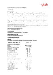
Pt 1000 temperature sensor (IEC 751B, 1000 Ω / 0 °C) Relationship between temperature and ohmic value:<br />
1600<br />
1500<br />
1400<br />
1300<br />
1200<br />
1100<br />
1000<br />
900<br />
800<br />
-50<br />
-25 0 25 50 75 100 125 150<br />
22 DEN-SMT/DK VI.GU.B1.02 <strong>Danfoss</strong> District Energy<br />
°C<br />
-50<br />
-40<br />
-30<br />
-20<br />
-10<br />
0<br />
10<br />
20<br />
30<br />
40<br />
50<br />
60<br />
70<br />
80<br />
90<br />
100<br />
110<br />
120<br />
130<br />
140<br />
150<br />
Ω<br />
803<br />
843<br />
882<br />
922<br />
961<br />
1000<br />
1039<br />
1078<br />
1117<br />
1155<br />
1194<br />
1232<br />
1271<br />
1309<br />
1347<br />
1385<br />
1423<br />
1461<br />
1498<br />
1535<br />
1573<br />
Ω<br />
°C
<strong>Installation</strong> <strong>Guide</strong> <strong>ECL</strong> <strong>Comfort</strong> <strong>310</strong>, <strong>application</strong> <strong>A376</strong><br />
2.5 Electrical connections<br />
2.5.1 Electrical connections 230 V a.c. in general<br />
The <strong>com</strong>mon ground terminal is used for connection of relevant<br />
<strong>com</strong>ponents (pumps, motorized control valves).<br />
<strong>Danfoss</strong> District Energy VI.GU.B1.02 DEN-SMT/DK 23
<strong>Installation</strong> <strong>Guide</strong> <strong>ECL</strong> <strong>Comfort</strong> <strong>310</strong>, <strong>application</strong> <strong>A376</strong><br />
2.5.2 Electrical connections, 230 V a.c., power supply, pumps, motorized control valves etc.<br />
<strong>A376</strong>.1, <strong>A376</strong>.2:<br />
Terminal Description Max. load<br />
19 Phase for alarm output<br />
18 Alarm 4 (2) A / 230 V a.c.*<br />
17 Not to be used<br />
16 Not to be used<br />
15 Not to be used<br />
14 Phase for circulation pumps<br />
13 P3 Heating circulation pump, ON / OFF, circuit 2 4 (2) A / 230 V a.c.*<br />
12 P2 Heating circulation pump, ON / OFF, circuit 1 4 (2) A / 230 V a.c.*<br />
11 P1 DHW circulation pump, ON / OFF, circuit 3 4 (2) A / 230 V a.c.*<br />
10 Supply voltage 230 V a.c. - neutral (N)<br />
9 Supply voltage 230 V a.c. - live (L)<br />
8 M1 Phase for motorized control valve output, circuit 3<br />
7 M1 Motorized control valve - opening 0.2 A / 230 V a.c.<br />
6 M1 Motorized control valve - closing 0.2 A / 230 V a.c.<br />
5 M2 Phase for motorized control valve output, circuit 1 and circuit 2<br />
4 M2 Motorized control valve - opening 0.2 A / 230 V a.c.<br />
3 M2 Motorized control valve - closing 0.2 A / 230 V a.c.<br />
2 M3 Motorized control valve - opening 0.2 A / 230 V a.c.<br />
1 M3 Motorized control valve - closing 0.2 A / 230 V a.c.<br />
* Relay contacts: 4 A for ohmic load, 2 A for inductive load<br />
Factory established jumpers:<br />
5 to 8, 9 to 14, L to 5 and L to 9, N to 10<br />
24 DEN-SMT/DK VI.GU.B1.02 <strong>Danfoss</strong> District Energy
<strong>Installation</strong> <strong>Guide</strong> <strong>ECL</strong> <strong>Comfort</strong> <strong>310</strong>, <strong>application</strong> <strong>A376</strong><br />
<strong>A376</strong>.3:<br />
Terminal Description Max. load<br />
19 Phase for alarm output<br />
18 Alarm 4 (2) A / 230 V a.c.*<br />
17 Not to be used<br />
16 Not to be used<br />
15 Not to be used<br />
14 Phase for circulation pumps<br />
13 P3 Heating circulation pump, ON / OFF, circuit 2 4 (2) A / 230 V a.c.*<br />
12 P2 Heating circulation pump, ON / OFF, circuit 1 4 (2) A / 230 V a.c.*<br />
11 P1 DHW circulation pump, ON / OFF, circuit 3 4 (2) A / 230 V a.c.*<br />
10 Supply voltage 230 V a.c. - neutral (N)<br />
9 Supply voltage 230 V a.c. - live (L)<br />
8 Not to be used<br />
7 Not to be used<br />
6 Not to be used<br />
5 Not to be used<br />
4 Not to be used<br />
3 Not to be used<br />
2 Not to be used<br />
1 Not to be used<br />
* Relay contacts: 4 A for ohmic load, 2 A for inductive load<br />
Factory established jumpers:<br />
5 to 8, 9 to 14, L to 5 and L to 9, N to 10<br />
<strong>Danfoss</strong> District Energy VI.GU.B1.02 DEN-SMT/DK 25<br />
<strong>Danfoss</strong><br />
87H2112.10
<strong>Installation</strong> <strong>Guide</strong> <strong>ECL</strong> <strong>Comfort</strong> <strong>310</strong>, <strong>application</strong> <strong>A376</strong><br />
<strong>A376</strong>.9:<br />
Terminal Description Max. load<br />
19<br />
18 R6<br />
17 R5 Not to be used<br />
16<br />
15<br />
Relay output, schedule in ‘Common controller settings’,<br />
4 (2) A / 230 V a.c.*<br />
Alarm 4 (2) A / 230 V a.c.*<br />
14 Phase for circulation pumps<br />
13 P3 Heating circulation pump, ON / OFF, circuit 2 4 (2) A / 230 V a.c.*<br />
12 P2 Heating circulation pump, ON / OFF, circuit 1 4 (2) A / 230 V a.c.*<br />
11 P1 DHW circulation pump, ON / OFF, circuit 3 4 (2) A / 230 V a.c.*<br />
10 Supply voltage 230 V a.c. - neutral (N)<br />
9 Supply voltage 230 V a.c. - live (L)<br />
8 M1 Phase for motorized control valve output, circuit 3<br />
7 M1 Motorized control valve - opening 0.2 A / 230 V a.c.<br />
6 M1 Motorized control valve - closing 0.2 A / 230 V a.c.<br />
5 M2 Phase for motorized control valve output, circuit 1 and circuit 2<br />
4 M2 Motorized control valve - opening 0.2 A / 230 V a.c.<br />
3 M2 Motorized control valve - closing 0.2 A / 230 V a.c.<br />
2 M3 Motorized control valve - opening 0.2 A / 230 V a.c.<br />
1 M3 Motorized control valve - closing 0.2 A / 230 V a.c.<br />
* Relay contacts: 4 A for ohmic load, 2 A for inductive load<br />
Factory established jumpers:<br />
5 to 8, 9 to 14, L to 5 and L to 9, N to 10<br />
For connection of the 0–10 V controlled motorized control valves, see<br />
Electrical connections, 24 V a.c. for ECA 32, <strong>application</strong> <strong>A376</strong>.3.<br />
26 DEN-SMT/DK VI.GU.B1.02 <strong>Danfoss</strong> District Energy
<strong>Installation</strong> <strong>Guide</strong> <strong>ECL</strong> <strong>Comfort</strong> <strong>310</strong>, <strong>application</strong> <strong>A376</strong><br />
Wire cross section: 0.5 - 1.5 mm²<br />
Incorrect connection can damage the electronic outputs.<br />
Max. 2 x 1.5 mm² wires can be inserted into each screw terminal.<br />
<strong>Danfoss</strong> District Energy VI.GU.B1.02 DEN-SMT/DK 27
<strong>Installation</strong> <strong>Guide</strong> <strong>ECL</strong> <strong>Comfort</strong> <strong>310</strong>, <strong>application</strong> <strong>A376</strong><br />
2.5.3 Electrical connections, safety thermostats, 230 V a.c. or 24 V a.c.<br />
With safety thermostat, 1–step closing:<br />
Motorized control valve without safety function<br />
<strong>ECL</strong> 210 / <strong>310</strong><br />
<strong>ECL</strong> 210 / <strong>310</strong><br />
With safety thermostat, 1–step closing:<br />
Motorized control valve with safety function<br />
<strong>ECL</strong> 210 / <strong>310</strong><br />
M1<br />
M2<br />
M1<br />
28 DEN-SMT/DK VI.GU.B1.02 <strong>Danfoss</strong> District Energy<br />
<strong>Danfoss</strong><br />
87H2105.10<br />
<strong>Danfoss</strong><br />
87H2106.10<br />
<strong>Danfoss</strong><br />
87H2107.10
<strong>Installation</strong> <strong>Guide</strong> <strong>ECL</strong> <strong>Comfort</strong> <strong>310</strong>, <strong>application</strong> <strong>A376</strong><br />
<strong>ECL</strong> 210 / <strong>310</strong><br />
With safety thermostat, 2–step closing:<br />
Motorized control valve with safety function<br />
<strong>ECL</strong> 210 / <strong>310</strong><br />
<strong>ECL</strong> 210 / <strong>310</strong><br />
M2<br />
M1<br />
M2<br />
When ST is activated by a high temperature, the safety circuit in the<br />
motorized control valve closes the valve immediately.<br />
When ST1 is activated by a high temperature (the TR temperature), the<br />
motorized control valve is closed gradually. At a higher temperature<br />
(the ST temperature), the safety circuit in the motorized control valve<br />
closes the valve immediately.<br />
<strong>Danfoss</strong> District Energy VI.GU.B1.02 DEN-SMT/DK 29<br />
<strong>Danfoss</strong><br />
87H2108.10<br />
<strong>Danfoss</strong><br />
87H2109.10<br />
<strong>Danfoss</strong><br />
87H2110.10
<strong>Installation</strong> <strong>Guide</strong> <strong>ECL</strong> <strong>Comfort</strong> <strong>310</strong>, <strong>application</strong> <strong>A376</strong><br />
Wire cross section: 0.5 - 1.5 mm²<br />
Incorrect connection can damage the electronic outputs.<br />
Max. 2 x 1.5 mm² wires can be inserted into each screw terminal.<br />
30 DEN-SMT/DK VI.GU.B1.02 <strong>Danfoss</strong> District Energy
<strong>Installation</strong> <strong>Guide</strong> <strong>ECL</strong> <strong>Comfort</strong> <strong>310</strong>, <strong>application</strong> <strong>A376</strong><br />
2.5.4 Electrical connections, 24 V a.c., power supply, pumps, motorized valves etc.<br />
<strong>A376</strong>.1, <strong>A376</strong>.2:<br />
Terminal Description Max. load<br />
19 Phase for alarm output<br />
18 Alarm 4 (2) A / 24 V a.c.*<br />
17 Not to be used<br />
16 Not to be used<br />
15 Not to be used<br />
14 Phase for circulation pumps<br />
13 K3 Heating circulation pump, ON / OFF, circuit 2 4 (2) A / 24 V a.c.*<br />
12 K2 Heating circulation pump, ON / OFF, circuit 1 4 (2) A / 24 V a.c.*<br />
11 K1 DHW circulation pump, ON / OFF, circuit 3 4 (2) A / 24 V a.c.*<br />
10 Supply voltage 24 V a.c. - (N)<br />
9 Supply voltage 24 V a.c. - (L)<br />
8 M1 Phase for motorized control valve output, circuit 3<br />
7 M1 Motorized control valve - opening 1 A / 24 V a.c.<br />
6 M1 Motorized control valve - closing 1 A / 24 V a.c.<br />
5 M2 Phase for motorized control valve output, circuit 1 and circuit 2<br />
4 M2 Motorized control valve - opening 1 A / 24 V a.c.<br />
3 M2 Motorized control valve - closing 1 A / 24 V a.c.<br />
2 M3 Motorized control valve - opening 1 A / 24 V a.c.<br />
1 M3 Motorized control valve - closing 1 A / 24 V a.c.<br />
* Relay contacts: 4 A for ohmic load, 2 A for inductive load<br />
Factory established jumpers:<br />
5 to 8, 9 to 14, L to 5 and L to 9, N to 10<br />
<strong>Danfoss</strong> District Energy VI.GU.B1.02 DEN-SMT/DK 31
<strong>Installation</strong> <strong>Guide</strong> <strong>ECL</strong> <strong>Comfort</strong> <strong>310</strong>, <strong>application</strong> <strong>A376</strong><br />
<strong>A376</strong>.3:<br />
Terminal Description Max. load<br />
19 Phase for alarm output<br />
18 Alarm 4 (2) A / 24 V a.c.*<br />
17 Not to be used<br />
16 Not to be used<br />
15 Not to be used<br />
14 Phase for circulation pumps<br />
13 K3 Heating circulation pump, ON / OFF, circuit 2 4 (2) A / 24 V a.c.*<br />
12 K2 Heating circulation pump, ON / OFF, circuit 1 4 (2) A / 24 V a.c.*<br />
11 K1 DHW circulation pump, ON / OFF, circuit 3 4 (2) A / 24 V a.c.*<br />
10 Supply voltage 24 V a.c. - (N)<br />
9 Supply voltage 24 V a.c. - (L)<br />
8 Not to be used<br />
7 Not to be used<br />
6 Not to be used<br />
5 Not to be used<br />
4 Not to be used<br />
3 Not to be used<br />
2 Not to be used<br />
1 Not to be used<br />
* Relay contacts: 4 A for ohmic load, 2 A for inductive load<br />
Factory established jumpers:<br />
5 to 8, 9 to 14, L to 5 and L to 9, N to 10<br />
32 DEN-SMT/DK VI.GU.B1.02 <strong>Danfoss</strong> District Energy
<strong>Installation</strong> <strong>Guide</strong> <strong>ECL</strong> <strong>Comfort</strong> <strong>310</strong>, <strong>application</strong> <strong>A376</strong><br />
<strong>A376</strong>.3 — ECA 32:<br />
Double-insulated (two-chamber) transformer<br />
Terminal Description Max. load<br />
49 Common terminal (connected to terminal 30 in the <strong>ECL</strong> <strong>Comfort</strong> controller)<br />
56 Analog reference for M2 and M3<br />
57 Not to be used<br />
58 Not to be used<br />
59 M1<br />
Analog Out 1:<br />
Motorized control valve, 0–10 V, circuit 3<br />
60 M2<br />
Analog Out 2:<br />
Motorized control valve, 0–10 V, circuit 1<br />
61 M3<br />
Analog Out 3:<br />
Motorized control valve, 0–10 V, circuit 2<br />
62 Analog reference for M1<br />
* The value must be 47 kΩ as a minimum.<br />
<strong>Danfoss</strong> District Energy VI.GU.B1.02 DEN-SMT/DK 33<br />
47 kΩ*<br />
47 kΩ*<br />
47 kΩ*
<strong>Installation</strong> <strong>Guide</strong> <strong>ECL</strong> <strong>Comfort</strong> <strong>310</strong>, <strong>application</strong> <strong>A376</strong><br />
<strong>A376</strong>.9:<br />
Terminal Description Max. load<br />
19<br />
18 R6<br />
17 R5 Not to be used<br />
16<br />
15<br />
Relay output, schedule in ‘Common controller settings’,<br />
4 (2) A / 24 V a.c.*<br />
Alarm 4 (2) A / 24 V a.c.*<br />
14 Phase for circulation pumps<br />
13 K3 Heating circulation pump, ON / OFF, circuit 2 4 (2) A / 24 V a.c.*<br />
12 K2 Heating circulation pump, ON / OFF, circuit 1 4 (2) A / 24 V a.c.*<br />
11 K1 DHW circulation pump, ON / OFF, circuit 3 4 (2) A / 24 V a.c.*<br />
10 Supply voltage 24 V a.c. - (N)<br />
9 Supply voltage 24 V a.c. - (L)<br />
8 M1 Phase for motorized control valve output, circuit 3<br />
7 M1 Motorized control valve - opening 1 A / 24 V a.c.<br />
6 M1 Motorized control valve - closing 1 A / 24 V a.c.<br />
5 M2 Phase for motorized control valve output, circuit 1 and circuit 2<br />
4 M2 Motorized control valve - opening 1 A / 24 V a.c.<br />
3 M2 Motorized control valve - closing 1 A / 24 V a.c.<br />
2 M3 Motorized control valve - opening 1 A / 24 V a.c.<br />
1 M3 Motorized control valve - closing 1 A / 24 V a.c.<br />
* Relay contacts: 4 A for ohmic load, 2 A for inductive load<br />
Factory established jumpers:<br />
5 to 8, 9 to 14, L to 5 and L to 9, N to 10<br />
Wire cross section: 0.5 - 1.5 mm²<br />
Incorrect connection can damage the electronic outputs.<br />
Max. 2 x 1.5 mm² wires can be inserted into each screw terminal.<br />
34 DEN-SMT/DK VI.GU.B1.02 <strong>Danfoss</strong> District Energy
<strong>Installation</strong> <strong>Guide</strong> <strong>ECL</strong> <strong>Comfort</strong> <strong>310</strong>, <strong>application</strong> <strong>A376</strong><br />
Do not connect 230 V a.c. powered <strong>com</strong>ponents to a 24 V a.c. power<br />
supplied controller directly. Use auxilliary relays (K) to seperate 230<br />
V a.c. from 24 V a.c.<br />
<strong>Danfoss</strong> District Energy VI.GU.B1.02 DEN-SMT/DK 35
<strong>Installation</strong> <strong>Guide</strong> <strong>ECL</strong> <strong>Comfort</strong> <strong>310</strong>, <strong>application</strong> <strong>A376</strong><br />
2.5.5 Electrical connections, Pt 1000 temperature sensors and signals<br />
<strong>A376</strong>:<br />
Terminal Sensor / description Type<br />
(re<strong>com</strong>m.)<br />
29 and 30 S1 Outdoor temperature<br />
sensor*<br />
ESMT<br />
28 and 30 S2 Room temperature<br />
sensor***, heating circuit 1<br />
(<strong>A376</strong>.1 / <strong>A376</strong>.3)<br />
ESM-10<br />
Room temperature<br />
sensor***, heating circuit 1 /<br />
2 (<strong>A376</strong>.2)<br />
ESM-10<br />
Return temperature sensor, ESM-11 / ESMB /<br />
monitoring only, circuit 1<br />
(<strong>A376</strong>.9)<br />
ESMC / ESMU<br />
27 and 30 S3 Flow temperature sensor, ESM-11 / ESMB /<br />
heating circuit 1** ESMC / ESMU<br />
26 and 30 S4 Flow temperature sensor, ESM-11 / ESMB /<br />
DHW circuit 3**<br />
ESMC / ESMU<br />
25 and 30 S5 Return temperature sensor, ESM-11 / ESMB /<br />
heating circuit 1<br />
ESMC / ESMU<br />
24 and 30 S6 Return temperature sensor, ESM-11 / ESMB /<br />
DHW circuit 3<br />
ESMC / ESMU<br />
23 and 30 S7 Room temperature<br />
sensor***: heating circuit 2<br />
(<strong>A376</strong>.1 / <strong>A376</strong>.3)<br />
ESM-10<br />
Supply flow temperature ESM-11 / ESMB /<br />
sensor (<strong>A376</strong>.2)<br />
0–10 V pressure transmitter<br />
signal (<strong>A376</strong>.9)<br />
ESMC / ESMU<br />
22 and 30 S8 Flow switch, only in <strong>A376</strong>.2<br />
Alarm input, only in <strong>A376</strong>.9<br />
21 and 30 S9 Flow temperature sensor**,<br />
heating circuit 2<br />
20 and 30 S10 Return temperature sensor,<br />
heating circuit 2<br />
Return temperature sensor,<br />
monitoring only, circuit 2<br />
(<strong>A376</strong>.9)<br />
ESM-11 / ESMB /<br />
ESMC / ESMU<br />
ESM-11 / ESMB /<br />
ESMC / ESMU<br />
ESM-11 / ESMB /<br />
ESMC / ESMU<br />
* If the outdoor temperature sensor is not connected or the<br />
cable is short-circuited, the controller assumes that the<br />
outdoor temperature is 0 (zero) °C. The outdoor temperature<br />
sensor is <strong>com</strong>mon for both heating circuits.<br />
** The flow temperature sensor must always be connected<br />
in order to have the desired functionality. If the sensor is<br />
not connected or the cable is short-circuited, the motorized<br />
control valve closes (safety function).<br />
*** Only for room temperature sensor connection. The room<br />
temperature signal can alternatively be available from a<br />
Remote Control Unit (ECA 30 / 31). See 'Electrical connections,<br />
ECA 30 / 31'.<br />
Factory established jumper:<br />
30 to <strong>com</strong>mon terminal.<br />
36 DEN-SMT/DK VI.GU.B1.02 <strong>Danfoss</strong> District Energy
<strong>Installation</strong> <strong>Guide</strong> <strong>ECL</strong> <strong>Comfort</strong> <strong>310</strong>, <strong>application</strong> <strong>A376</strong><br />
<strong>A376</strong>.9 — ECA 32:<br />
Terminal Sensor / description Type<br />
(re<strong>com</strong>m.)<br />
50 and 49 S11 Supply flow temperature ESM-11 / ESMB /<br />
sensor*<br />
ESMC / ESMU<br />
51 and 49 S12 Return temperature sensor ESM-11 / ESMB /<br />
ESMC / ESMU<br />
52 and 49 S13 Return temperature sensor, ESM-11 / ESMB /<br />
heating circuit 2<br />
ESMC / ESMU<br />
53 and 49 S14 0-10 V pressure transmitter<br />
signal<br />
54 and 49 S15 Alarm input, only in <strong>A376</strong>.9<br />
55 and 49 S16 Alarm input, only in <strong>A376</strong>.9<br />
* The supply flow temperature sensor must always be<br />
connected in order to have the desired functionality.<br />
Factory established jumper:<br />
49 to <strong>com</strong>mon terminal.<br />
Connection of flow switch<br />
Connection of switches, ECA 32<br />
Wire cross section for sensor connections: Min. 0.4 mm².<br />
Total cable length: Max. 200 m (all sensors incl. internal <strong>ECL</strong> 485<br />
<strong>com</strong>munication bus)<br />
Cable lengths of more than 200 m may cause noise sensibility (EMC).<br />
<strong>Danfoss</strong> District Energy VI.GU.B1.02 DEN-SMT/DK 37
<strong>Installation</strong> <strong>Guide</strong> <strong>ECL</strong> <strong>Comfort</strong> <strong>310</strong>, <strong>application</strong> <strong>A376</strong><br />
Connection of a pressure transmitter with 0-10 V output, S7<br />
Connection of a pressure transmitter with 0-10 V output, ECA<br />
32, S14<br />
Connection of a pressure transmitter with 4-20 mA output, S7<br />
The 4-20 mA signal is converted to a 0-10 V signal by means of the<br />
500 ohm resistor.<br />
Connection of a pressure transmitter with 4-20 mA output,<br />
ECA 32, S14<br />
The 4-20 mA signal is converted to a 0-10 V signal by means of the<br />
500 ohm resistor.<br />
Connection of CW meter, <strong>A376</strong>.9<br />
38 DEN-SMT/DK VI.GU.B1.02 <strong>Danfoss</strong> District Energy
<strong>Installation</strong> <strong>Guide</strong> <strong>ECL</strong> <strong>Comfort</strong> <strong>310</strong>, <strong>application</strong> <strong>A376</strong><br />
2.5.6 Electrical connections, ECA 30 / 31<br />
Terminal Terminal<br />
ECA 30 / 31<br />
30 4<br />
31 1<br />
32 2<br />
33 3<br />
4<br />
5<br />
Description Type<br />
(re<strong>com</strong>m.)<br />
Twisted pair<br />
Twisted pair<br />
Ext. room temperature<br />
sensor*<br />
Cable 2 x<br />
twisted pair<br />
ESM-10<br />
* After an external room temperature sensor has been connected,<br />
ECA 30 / 31 must be repowered.<br />
The <strong>com</strong>munication to the ECA 30 / 31 must be set up in the <strong>ECL</strong><br />
<strong>Comfort</strong> controller in 'ECA addr.'<br />
The ECA 30 /31 must be set up accordingly.<br />
After <strong>application</strong> setup the ECA 30 / 31 is ready after 2–5 min. A<br />
progress bar in the ECA 30 / 31 is displayed.<br />
ECA 30 / 31<br />
ESM-10<br />
<strong>ECL</strong> 210 / <strong>310</strong><br />
ECA information message:<br />
‘Application req. newer ECA’:<br />
The software of your ECA does not <strong>com</strong>ply with the software of your<br />
<strong>ECL</strong> <strong>Comfort</strong> controller. Please contact your <strong>Danfoss</strong> sales office.<br />
Some <strong>application</strong>s do not contain functions related to actual room<br />
temperature. The connected ECA 30 / 31 will only function as remote<br />
control.<br />
Total cable length: Max. 200 m (all sensors incl. internal <strong>ECL</strong> 485<br />
<strong>com</strong>munication bus).<br />
Cable lengths of more than 200 m may cause noise sensibility (EMC).<br />
Max. two ECA 30 / 31 can be connected to an <strong>ECL</strong> <strong>Comfort</strong> controller.<br />
An ECA 30 / 31 can be connected to each of the heating circuits.<br />
<strong>Danfoss</strong> District Energy VI.GU.B1.02 DEN-SMT/DK 39<br />
B<br />
A<br />
B<br />
A<br />
<strong>Danfoss</strong><br />
87H2051.10
<strong>Installation</strong> <strong>Guide</strong> <strong>ECL</strong> <strong>Comfort</strong> <strong>310</strong>, <strong>application</strong> <strong>A376</strong><br />
2.5.7 Electrical connections, master / slave systems<br />
The controller can be used as master or slave in master / slave<br />
systems via the internal <strong>ECL</strong> 485 <strong>com</strong>munication bus (2 x twisted<br />
pair cable).<br />
The <strong>ECL</strong> 485 <strong>com</strong>munication bus is not <strong>com</strong>patible with the <strong>ECL</strong><br />
bus in <strong>ECL</strong> <strong>Comfort</strong> 110, 200, 300 and 301!<br />
Terminal Description Type<br />
(re<strong>com</strong>m.)<br />
30 Common terminal<br />
31* +12 V*, <strong>ECL</strong> 485 <strong>com</strong>munication bus<br />
32 A, <strong>ECL</strong> 485 <strong>com</strong>munication bus<br />
33 B, <strong>ECL</strong> 485 <strong>com</strong>munication bus<br />
Cable 2 x<br />
twisted pair<br />
* Only for ECA 30 / 31 and master / slave <strong>com</strong>munication<br />
B<br />
A<br />
B<br />
A<br />
Settings related to master / slave <strong>com</strong>munication:<br />
See ‘Several controllers in the same system’ in ‘Miscellaneous’.<br />
Total cable length: Max. 200 m (all sensors incl. internal <strong>ECL</strong> 485<br />
<strong>com</strong>munication bus).<br />
Cable lengths of more than 200 m may cause noise sensibility (EMC).<br />
40 DEN-SMT/DK VI.GU.B1.02 <strong>Danfoss</strong> District Energy<br />
B<br />
A<br />
B<br />
A<br />
<strong>Danfoss</strong><br />
87H2052.10
<strong>Installation</strong> <strong>Guide</strong> <strong>ECL</strong> <strong>Comfort</strong> <strong>310</strong>, <strong>application</strong> <strong>A376</strong><br />
2.5.8 Electrical connections, <strong>com</strong>munication<br />
Electrical connections, Modbus<br />
Electrical connections, M-bus<br />
<strong>ECL</strong> 210 / <strong>310</strong><br />
<strong>ECL</strong> <strong>310</strong><br />
<strong>Danfoss</strong> District Energy VI.GU.B1.02 DEN-SMT/DK 41<br />
B<br />
A<br />
B<br />
A<br />
B<br />
A<br />
B<br />
A<br />
<strong>Danfoss</strong><br />
87H2060.10<br />
<strong>Danfoss</strong><br />
87H2061.10
<strong>Installation</strong> <strong>Guide</strong> <strong>ECL</strong> <strong>Comfort</strong> <strong>310</strong>, <strong>application</strong> <strong>A376</strong><br />
2.6 Inserting the <strong>ECL</strong> Application Key<br />
2.6.1 Inserting the <strong>ECL</strong> Application Key<br />
The <strong>ECL</strong> Application Key contains<br />
• the <strong>application</strong> and its subtypes,<br />
• currently available languages,<br />
• factory settings: e.g. schedules, desired temperatures,<br />
limitation values etc. It is always possible to recover the factory<br />
settings,<br />
• memory for user settings: special user / system settings.<br />
After having powered-up the controller, different situations might<br />
be existing:<br />
1. The controller is new from the factory, the <strong>ECL</strong> Application Key<br />
is not inserted.<br />
2. The controller already runs an <strong>application</strong>. The <strong>ECL</strong> Application<br />
Key is inserted, but the <strong>application</strong> needs to be changed.<br />
3. A copy of the controllers settings is needed for configuring<br />
another controller.<br />
User settings are, among others, desired room temperature, desired<br />
DHW temperature, schedules, heat curve, limitation values etc.<br />
System settings are, among others, <strong>com</strong>munication set-up, display<br />
brightness etc.<br />
Automatic update of controller software:<br />
The software of the controller is updated automatically when the key<br />
is inserted (as of controller version 1.11). The following animation will<br />
be shown when the software is being updated:<br />
Progress bar<br />
42 DEN-SMT/DK VI.GU.B1.02 <strong>Danfoss</strong> District Energy
<strong>Installation</strong> <strong>Guide</strong> <strong>ECL</strong> <strong>Comfort</strong> <strong>310</strong>, <strong>application</strong> <strong>A376</strong><br />
Application Key: Situation 1<br />
The controller is new from the factory, the <strong>ECL</strong> Application Key<br />
is not inserted.<br />
An animation for the <strong>ECL</strong> Application Key insertion is displayed.<br />
Insert the Application Key .<br />
Application Key name and Version is indicated (example: A266<br />
Ver. 1.03).<br />
If the <strong>ECL</strong> Application Key is not suitable for the controller, a "cross"<br />
is displayed over the <strong>ECL</strong> Application Key-symbol.<br />
Action: Purpose: Examples:<br />
Select language<br />
Confirm<br />
Select <strong>application</strong><br />
Confirm with ‘Yes’<br />
Set 'Time & Date'<br />
Turn and push the dial to select and<br />
change 'Hours', 'Minutes', 'Date',<br />
'Month' and 'Year'.<br />
Choose ''Next'<br />
Confirm with ‘Yes’<br />
Go to ‘Aut. daylight’<br />
Choose whether ‘Aut. daylight´ *<br />
should be active or not<br />
YES or NO<br />
* ‘Aut. daylight’ is the automatic changeover between summer<br />
and winter time.<br />
Depending on the contents of the <strong>ECL</strong> Application Key, procedure<br />
A or B is taking place:<br />
A<br />
The <strong>ECL</strong> Application key contains factory settings:<br />
The controller reads / transfers data from the <strong>ECL</strong> Application Key<br />
to <strong>ECL</strong> controller.<br />
The <strong>application</strong> is installed, and the controller resets and starts up.<br />
B<br />
The <strong>ECL</strong> Application key contains changed system settings:<br />
Push the dial repeatedly.<br />
’NO’: Only factory settings from the <strong>ECL</strong> Application Key will<br />
be copied to the controller.<br />
’YES*: Special system settings (differing from the factory<br />
settings) will be copied to the controller.<br />
If the key contains user settings:<br />
Push the dial repeatedly.<br />
‘NO: Only factory settings from the <strong>ECL</strong> Application Key will<br />
be copied to the controller.<br />
‘YES*: Special user settings (differing from the factory settings)<br />
will be copied to the controller.<br />
* If ‘YES’ cannot be chosen, the <strong>ECL</strong> Application Key does not<br />
contain any special settings.<br />
Choose ‘Start copying’ and confirm with 'Yes'.<br />
<strong>Danfoss</strong> District Energy VI.GU.B1.02 DEN-SMT/DK 43
<strong>Installation</strong> <strong>Guide</strong> <strong>ECL</strong> <strong>Comfort</strong> <strong>310</strong>, <strong>application</strong> <strong>A376</strong><br />
Application Key: Situation 2<br />
The controller already runs an <strong>application</strong>. The <strong>ECL</strong> Application<br />
Key is inserted, but the <strong>application</strong> needs to be changed.<br />
To change to another <strong>application</strong> on the <strong>ECL</strong> Application Key, the<br />
current <strong>application</strong> in the controller must be erased (deleted).<br />
Be aware that the Application Key must be inserted.<br />
Action: Purpose: Examples:<br />
Choose ‘MENU’ in any circuit<br />
Confirm<br />
Choose the circuit selector at the top<br />
right corner in the display<br />
Confirm<br />
Choose ‘Common controller settings’<br />
Confirm<br />
Choose ‘Key functions’<br />
Confirm<br />
Choose ‘Erase <strong>application</strong>’<br />
Confirm with ‘Yes’<br />
The controller resets and is ready to be configured.<br />
Follow the procedure described in situation 1.<br />
44 DEN-SMT/DK VI.GU.B1.02 <strong>Danfoss</strong> District Energy
<strong>Installation</strong> <strong>Guide</strong> <strong>ECL</strong> <strong>Comfort</strong> <strong>310</strong>, <strong>application</strong> <strong>A376</strong><br />
Application Key: Situation 3<br />
A copy of the controllers settings is needed for configuring<br />
another controller.<br />
This function is used<br />
• for saving (backup) of special user and system settings<br />
• when another <strong>ECL</strong> <strong>Comfort</strong> controller of the same type (210 or<br />
<strong>310</strong>) must be configured with the same <strong>application</strong> but user /<br />
system settings differ from the factory settings.<br />
How to copy to another <strong>ECL</strong> <strong>Comfort</strong> controller:<br />
*<br />
Action: Purpose: Examples:<br />
Choose ‘MENU’<br />
Confirm<br />
Choose the circuit selector at the top<br />
right corner in the display<br />
Confirm<br />
Choose 'Common controller settings'<br />
Confirm<br />
Go to ‘Key functions’<br />
Confirm<br />
Choose ‘Copy’<br />
Confirm<br />
Choose ‘To’.<br />
‘<strong>ECL</strong>’ or ‘KEY’ will be indicated. Choose<br />
’<strong>ECL</strong>’ or KEY’<br />
Push the dial repeatedly to choose<br />
copy direction<br />
Choose ‘System settings’ or ‘User<br />
settings’<br />
Push the dial repeatedly to choose<br />
‘Yes’ or ‘No’ in ‘Copy’. Push to confirm.<br />
Choose ‘Start copying’<br />
The Application Key or the controller<br />
is updated with special system or user<br />
settings.<br />
*<br />
’<strong>ECL</strong>’ or ‘KEY’.<br />
**<br />
‘NO’ or ‘YES’<br />
‘<strong>ECL</strong>’: Data will be copied from the Application Key to the<br />
<strong>ECL</strong> Controller.<br />
‘KEY’: Data will be copied from the <strong>ECL</strong> Controller to the<br />
Application Key.<br />
**<br />
‘NO’: The settings from the <strong>ECL</strong> controller will not be copied<br />
to the Application Key or to the <strong>ECL</strong> <strong>Comfort</strong> controller.<br />
‘YES’: Special settings (differing from the factory settings) will<br />
be copied to the Application Key or to the <strong>ECL</strong> <strong>Comfort</strong><br />
controller. If YES can not be chosen, there are no special<br />
settings to be copied.<br />
<strong>Danfoss</strong> District Energy VI.GU.B1.02 DEN-SMT/DK 45
<strong>Installation</strong> <strong>Guide</strong> <strong>ECL</strong> <strong>Comfort</strong> <strong>310</strong>, <strong>application</strong> <strong>A376</strong><br />
2.6.2 <strong>ECL</strong> Application Key, copying data<br />
General principles<br />
When the controller is connected and operating, you can check<br />
and adjust all or some of the basic settings. The new settings can<br />
be stored on the Key.<br />
How to update the <strong>ECL</strong> Application Key after settings have<br />
been changed?<br />
All new settings can be stored on the <strong>ECL</strong> Application Key.<br />
How to store factory setting in the controller from the<br />
Application Key?<br />
Please read the paragraph concerning Application Key, Situation<br />
1: The controller is new from the factory, the <strong>ECL</strong> Application Key<br />
is not inserted.<br />
How to store personal settings from the controller to the Key?<br />
Please read the paragraph concerning Application Key, Situation 3:<br />
A copy of the controllers settings is needed for configuring another<br />
controller<br />
As a main rule, the <strong>ECL</strong> Application Key should always remain in<br />
the controller. If the Key is removed, it is not possible to change<br />
settings.<br />
Factory settings can always be restored.<br />
Make a note of new settings in the 'Settings overview' table.<br />
Do not remove the <strong>ECL</strong> Application Key while copying. The data on<br />
the <strong>ECL</strong> Application Key can be damaged!<br />
It is possible to copy settings from one <strong>ECL</strong> <strong>Comfort</strong> controller to<br />
another controller provided that the two controllers are from the same<br />
series (210 or <strong>310</strong>).<br />
46 DEN-SMT/DK VI.GU.B1.02 <strong>Danfoss</strong> District Energy
<strong>Installation</strong> <strong>Guide</strong> <strong>ECL</strong> <strong>Comfort</strong> <strong>310</strong>, <strong>application</strong> <strong>A376</strong><br />
2.7 Check list<br />
Is the <strong>ECL</strong> <strong>Comfort</strong> controller ready for use?<br />
Make sure that the correct power supply is connected to terminals 9 (Live) and 10 (Neutral).<br />
Check that the required controlled <strong>com</strong>ponents (actuator, pump etc.) are connected to the correct terminals.<br />
Check that all sensors / signals are connected to the correct terminals (see 'Electrical connections').<br />
Mount the controller and switch on the power.<br />
Is the <strong>ECL</strong> Application Key inserted (see 'Inserting the Application Key').<br />
Is the correct language chosen (see 'Language' in 'Common controller settings').<br />
Is the time & date set correctly (see 'Time & Date' in 'Common controller settings').<br />
Is the right <strong>application</strong> chosen (see 'Identifying the system type').<br />
Check that all settings in the controller (see 'Settings overview') are set or that the factory settings <strong>com</strong>ply with your<br />
requirements.<br />
Choose manual operation (see 'Manual control'). Check that valves open and close, and that required controlled<br />
<strong>com</strong>ponents (pump etc.) start and stop when operated manually.<br />
Check that the temperatures / signals shown in the display match the actual connected <strong>com</strong>ponents.<br />
Having <strong>com</strong>pleted the manual operation check, choose controller mode (scheduled, <strong>com</strong>fort, saving or frost protection).<br />
<strong>Danfoss</strong> District Energy VI.GU.B1.02 DEN-SMT/DK 47
<strong>Installation</strong> <strong>Guide</strong> <strong>ECL</strong> <strong>Comfort</strong> <strong>310</strong>, <strong>application</strong> <strong>A376</strong><br />
2.8 Navigation, <strong>ECL</strong> Application Key <strong>A376</strong><br />
Navigation, <strong>application</strong> <strong>A376</strong>.1<br />
Home Heating, circuit 1 Heating, circuit 2 DHW, circuit 3<br />
ID no. Function ID no. Function ID no. Function<br />
MENU<br />
Schedule Selectable Selectable Selectable<br />
Settings Flow temperature Heat curve Heat curve<br />
11178 Temp. max. 12178 Temp. max. 13178 Temp. max.<br />
11177 Temp. min. 12177 Temp. min. 13177 Temp. min<br />
Room limit 11182 Infl. — max. 12182 Infl. — max.<br />
11183 Infl. — min. 12183 Infl. — min.<br />
11015 Adapt. time 12015 Adapt. time<br />
Return limit 11031 High T out X1 12031 High T out X1 13030 Limit<br />
11032 Low limit Y1 12032 Low limit Y1<br />
11033 Low T out X2 12033 Low T out X2<br />
11034 High limit Y2 12034 High limit Y2<br />
11035 Infl. - max. 12035 Infl. - max. 13035 Infl. - max.<br />
11036 Infl. - min. 12036 Infl. - min. 13036 Infl. - min.<br />
11037 Adapt. time 12037 Adapt. time 13037 Adapt. time<br />
11085 Priority 12085 Priority 13085 Priority<br />
Flow / power limit Actual Actual Actual<br />
Actual limit Actual limit 13111 Limit<br />
11119 High T out X1 12119 High T out X1<br />
11117 Low limit Y1 12117 Low limit Y1<br />
11118 Low T out X2 12118 Low T out X2<br />
11116 High limit Y2 12116 High limit Y2<br />
11112 Adapt. time 12112 Adapt. time 13112 Adapt. time<br />
11113 Filter constant 12113 Filter constant 13113 Filter constant<br />
11109 Input type 12109 Input type 1<strong>310</strong>9 Input type<br />
11115 Units 12115 Units 13115 Units<br />
Optimization 11011 Auto saving 12011 Auto saving<br />
11012 Boost 12012 Boost<br />
11013 Ramp 12013 Ramp<br />
11014 Optimizer 12014 Optimizer<br />
11026 Pre-stop 12026 Pre-stop<br />
11020 Based on 12020 Based on<br />
11021 Total stop 12021 Total stop<br />
11179 Cut-out 12179 Cut-out<br />
11043 Parallel operation 12043 Parallel operation<br />
Control par. 13173 Auto tuning<br />
11174 Motor pr. 12174 Motor pr. 13174 Motor pr.<br />
11184 Xp 12184 Xp 13184 Xp<br />
11185 Tn 12185 Tn 13185 Tn<br />
11186 M run 12186 M run 13186 M run<br />
11187 Nz 12187 Nz 13187 Nz<br />
11189 Min. act. time 12189 Min. act. time 13189 Min. act. time<br />
48 DEN-SMT/DK VI.GU.B1.02 <strong>Danfoss</strong> District Energy
<strong>Installation</strong> <strong>Guide</strong> <strong>ECL</strong> <strong>Comfort</strong> <strong>310</strong>, <strong>application</strong> <strong>A376</strong><br />
Navigation, <strong>application</strong> <strong>A376</strong>.1, continued<br />
Home Heating, circuit 1 Heating, circuit 2 DHW, circuit 3<br />
MENU<br />
ID no. Function ID no. Function ID no. Function<br />
Settings Application 11010 ECA addr. 12010 ECA addr.<br />
11017 Demand offset<br />
11050 P demand<br />
11500 Send desired T 12500 Send desired T 13500 Send desired T<br />
11022 P exercise 12022 P exercise 13022 P exercise<br />
11023 M exercise 12023 M exercise 13023 M exercise<br />
11052 DHW priority 12052 DHW priority<br />
11077 P frost T 12077 P frost T 13077 P frost T<br />
11078 P heat T 12078 P heat T 13078 P heat T<br />
11040 P post-run 12040 P post-run 13040 P post-run<br />
11093 Frost pr. T 12093 Frost pr. T 13093 Frost pr. T<br />
11141 Ext. input 12141 Ext. input 13141 Ext. input<br />
11142 Ext. mode 12142 Ext. mode 13142 Ext. mode<br />
Anti-bacteria Selectable<br />
Holiday Selectable Selectable Selectable<br />
Alarm Temp. monitor. 11147 Upper difference 12147 Upper difference 13147 Upper difference<br />
Influence<br />
overview<br />
11148 Lower difference 12148 Lower difference 13148 Lower difference<br />
11149 Delay 12149 Delay 13149 Delay<br />
11150 Lowest temp. 12150 Lowest temp. 13150 Lowest temp.<br />
Alarm overview Selectable Selectable Selectable<br />
Des. flow T<br />
Return lim. Return lim. Return lim.<br />
Room lim. Room lim.<br />
Parallel priority Parallel priority<br />
Flow / power lim. Flow / power lim. Flow / power lim.<br />
Holiday Holiday Holiday<br />
Ext. override Ext. override Ext. override<br />
ECA override ECA override Anti-bacteria<br />
Boost Boost<br />
Ramp Ramp<br />
Slave, demand<br />
Heating cut-out Heating cut-out<br />
DHW priority DHW priority<br />
SCADA offset SCADA offset SCADA offset<br />
<strong>Danfoss</strong> District Energy VI.GU.B1.02 DEN-SMT/DK 49
<strong>Installation</strong> <strong>Guide</strong> <strong>ECL</strong> <strong>Comfort</strong> <strong>310</strong>, <strong>application</strong> <strong>A376</strong><br />
Navigation, <strong>application</strong> <strong>A376</strong>.1, Common controller settings<br />
Home Common controller settings<br />
MENU ID no. Function<br />
Time & Date Selectable<br />
Holiday Selectable<br />
Input overview 1, 2 & 3 Circuit 1 Circuit 2 Circuit 3<br />
Outdoor T Outdoor T DHW flow T<br />
Outdoor acc. T Outdoor acc. T DHW return T<br />
Room T Room T<br />
Heat flow T Heat flow T<br />
Heat return T Heat return T<br />
Log 1, 2 & 3 (sensors) Log today Outdoor T Outdoor T DHW flow & des.<br />
Log yesterday Heating flow & des. Heating flow & des. DHW return T<br />
Log 2 days Heat return T & limit Heat return T & limit<br />
Log 4 days Room T Room T<br />
Output override M1, P1, M2, P2, M3, P3, A1<br />
Key functions New <strong>application</strong> Erase <strong>application</strong><br />
Application<br />
Factory setting System settings<br />
User settings<br />
Go to factory<br />
Copy To<br />
System settings<br />
User settings<br />
Start copying<br />
Key overview<br />
System <strong>ECL</strong> version Code no.<br />
Hardware<br />
Software<br />
Build no.<br />
Serial no.<br />
MAC<br />
Production week<br />
Extension<br />
Ethernet<br />
M-bus config Selectable<br />
Energy Meters Selectable<br />
Display 60058 Backlight<br />
60059 Contrast<br />
Communication 38 Modbus addr.<br />
2048 <strong>ECL</strong> 485 addr.<br />
2150 Service pin<br />
2151 Ext. reset<br />
Language 2050 Language<br />
50 DEN-SMT/DK VI.GU.B1.02 <strong>Danfoss</strong> District Energy
<strong>Installation</strong> <strong>Guide</strong> <strong>ECL</strong> <strong>Comfort</strong> <strong>310</strong>, <strong>application</strong> <strong>A376</strong><br />
Navigation, <strong>application</strong> <strong>A376</strong>.2<br />
Home Heating, circuit 1 Heating, circuit 2 DHW, circuit 3<br />
ID no. Function ID no. Function ID no. Function<br />
MENU<br />
Schedule Selectable Selectable Selectable<br />
Settings Flow temperature Heat curve Heat curve<br />
11178 Temp. max. 12178 Temp. max. 13178 Temp. max.<br />
11177 Temp. min. 12177 Temp. min. 13177 Temp. min<br />
Room limit 11182 Infl. — max. 12182 Infl. — max.<br />
11183 Infl. — min. 12183 Infl. — min.<br />
11015 Adapt. time 12015 Adapt. time<br />
Return limit 11031 High T out X1 12031 High T out X1 13030 Limit<br />
11032 Low limit Y1 12032 Low limit Y1<br />
11033 Low T out X2 12033 Low T out X2<br />
11034 High limit Y2 12034 High limit Y2<br />
11035 Infl. - max. 12035 Infl. - max. 13035 Infl. - max.<br />
11036 Infl. - min. 12036 Infl. - min. 13036 Infl. - min.<br />
11037 Adapt. time 12037 Adapt. time 13037 Adapt. time<br />
11085 Priority 12085 Priority 13085 Priority<br />
Flow / power limit Actual Actual Actual<br />
Actual limit Actual limit 13111 Limit<br />
11119 High T out X1 12119 High T out X1<br />
11117 Low limit Y1 12117 Low limit Y1<br />
11118 Low T out X2 12118 Low T out X2<br />
11116 High limit Y2 12116 High limit Y2<br />
11112 Adapt. time 12112 Adapt. time 13112 Adapt. time<br />
11113 Filter constant 12113 Filter constant 13113 Filter constant<br />
11109 Input type 12109 Input type 1<strong>310</strong>9 Input type<br />
11115 Units 12115 Units 13115 Units<br />
Optimization 11011 Auto saving 12011 Auto saving<br />
11012 Boost 12012 Boost<br />
11013 Ramp 12013 Ramp<br />
11014 Optimizer 12014 Optimizer<br />
11026 Pre-stop 12026 Pre-stop<br />
11020 Based on 12020 Based on<br />
11021 Total stop 12021 Total stop<br />
11179 Cut-out 12179 Cut-out<br />
11043 Parallel operation 12043 Parallel operation<br />
Control par. 13173 Auto tuning<br />
11174 Motor pr. 12174 Motor pr. 13174 Motor pr.<br />
11184 Xp 12184 Xp Xp actual<br />
11185 Tn 12185 Tn 13185 Tn<br />
11186 M run 12186 M run 13186 M run<br />
11187 Nz 12187 Nz 13187 Nz<br />
11189 Min. act. time 12189 Min. act. time 13189 Min. act. time<br />
13097 Supply T (idle)<br />
13096 Tn (idle)<br />
13094 Open time<br />
13095 Close time<br />
<strong>Danfoss</strong> District Energy VI.GU.B1.02 DEN-SMT/DK 51
<strong>Installation</strong> <strong>Guide</strong> <strong>ECL</strong> <strong>Comfort</strong> <strong>310</strong>, <strong>application</strong> <strong>A376</strong><br />
Navigation, <strong>application</strong> <strong>A376</strong>.2, continued<br />
Home Heating, circuit 1 Heating, circuit 2 DHW, circuit 3<br />
MENU<br />
ID no. Function ID no. Function ID no. Function<br />
Settings Application 11010 ECA addr. 12010 ECA addr.<br />
11017 Demand offset<br />
11050 P demand<br />
11500 Send desired T 12500 Send desired T 13500 Send desired T<br />
11022 P exercise 12022 P exercise 13022 P exercise<br />
11023 M exercise 12023 M exercise 13023 M exercise<br />
11052 DHW priority 12052 DHW priority<br />
11077 P frost T 12077 P frost T 13077 P frost T<br />
11078 P heat T 12078 P heat T 13078 P heat T<br />
11040 P post-run 12040 P post-run 13040 P post-run<br />
11093 Frost pr. T 12093 Frost pr. T 13093 Frost pr. T<br />
11141 Ext. input 12141 Ext. input 13141 Ext. input<br />
11142 Ext. mode 12142 Ext. mode 13142 Ext. mode<br />
Anti-bacteria Selectable<br />
Holiday Selectable Selectable Selectable<br />
Alarm Temp. monitor. 11147 Upper difference 12147 Upper difference 13147 Upper difference<br />
Influence<br />
overview<br />
11148 Lower difference 12148 Lower difference 13148 Lower difference<br />
11149 Delay 12149 Delay 13149 Delay<br />
11150 Lowest temp. 12150 Lowest temp. 13150 Lowest temp.<br />
Alarm overview Selectable Selectable Selectable<br />
Des. flow T<br />
Return lim. Return lim. Return lim.<br />
Room lim. Room lim.<br />
Parallel priority Parallel priority<br />
Flow / power lim. Flow / power lim. Flow / power lim.<br />
Holiday Holiday Holiday<br />
Ext. override Ext. override Ext. override<br />
ECA override ECA override Anti-bacteria<br />
Boost Boost<br />
Ramp Ramp<br />
Slave, demand<br />
Heating cut-out Heating cut-out<br />
DHW priority DHW priority<br />
SCADA offset SCADA offset SCADA offset<br />
52 DEN-SMT/DK VI.GU.B1.02 <strong>Danfoss</strong> District Energy
<strong>Installation</strong> <strong>Guide</strong> <strong>ECL</strong> <strong>Comfort</strong> <strong>310</strong>, <strong>application</strong> <strong>A376</strong><br />
Navigation, <strong>application</strong> <strong>A376</strong>.2, Common controller settings<br />
Home Common controller settings<br />
MENU ID no. Function<br />
Time & Date Selectable<br />
Holiday Selectable<br />
Input overview 1, 2 & 3 Circuit 1 Circuit 2 Circuit 3<br />
Outdoor T Outdoor T DHW flow T<br />
Outdoor acc. T Outdoor acc. T DHW return T<br />
Room T Room T Supply T<br />
Heat flow T Heat flow T Flow switch<br />
Heat return T Heat return T<br />
Log 1, 2 & 3 (sensors) Log today Outdoor T Outdoor T DHW flow & des.<br />
Log yesterday Heating flow & des. Heating flow & des. DHW return T<br />
Log 2 days Heat return T & limit Heat return T & limit Supply T<br />
Log 4 days Room T Room T<br />
Output override M1, P1, M2, P2, M3, P3, A1<br />
Key functions New <strong>application</strong> Erase <strong>application</strong><br />
Application<br />
Factory setting System settings<br />
User settings<br />
Go to factory<br />
Copy To<br />
System settings<br />
User settings<br />
Start copying<br />
Key overview<br />
System <strong>ECL</strong> version Code no.<br />
Hardware<br />
Software<br />
Build no.<br />
Serial no.<br />
MAC<br />
Production week<br />
Extension<br />
Ethernet<br />
M-bus config Selectable<br />
Energy Meters Selectable<br />
Display 60058 Backlight<br />
60059 Contrast<br />
Communication 38 Modbus addr.<br />
2048 <strong>ECL</strong> 485 addr.<br />
2150 Service pin<br />
2151 Ext. reset<br />
Language 2050 Language<br />
<strong>Danfoss</strong> District Energy VI.GU.B1.02 DEN-SMT/DK 53
<strong>Installation</strong> <strong>Guide</strong> <strong>ECL</strong> <strong>Comfort</strong> <strong>310</strong>, <strong>application</strong> <strong>A376</strong><br />
Navigation, <strong>application</strong> <strong>A376</strong>.3<br />
Home Heating, circuit 1 Heating, circuit 2 DHW, circuit 3<br />
ID no. Function ID no. Function ID no. Function<br />
MENU<br />
Schedule Selectable Selectable Selectable<br />
Settings Flow temperature Heat curve Heat curve<br />
11178 Temp. max. 12178 Temp. max. 13178 Temp. max.<br />
11177 Temp. min. 12177 Temp. min. 13177 Temp. min<br />
Room limit 11182 Infl. — max. 12182 Infl. — max.<br />
11183 Infl. — min. 12183 Infl. — min.<br />
11015 Adapt. time 12015 Adapt. time<br />
Return limit 11031 High T out X1 12031 High T out X1 13030 Limit<br />
11032 Low limit Y1 12032 Low limit Y1<br />
11033 Low T out X2 12033 Low T out X2<br />
11034 High limit Y2 12034 High limit Y2<br />
11035 Infl. - max. 12035 Infl. - max. 13035 Infl. - max.<br />
11036 Infl. - min. 12036 Infl. - min. 13036 Infl. - min.<br />
11037 Adapt. time 12037 Adapt. time 13037 Adapt. time<br />
11085 Priority 12085 Priority 13085 Priority<br />
Flow / power limit Actual Actual Actual<br />
Actual limit Actual limit 13111 Limit<br />
11119 High T out X1 12119 High T out X1<br />
11117 Low limit Y1 12117 Low limit Y1<br />
11118 Low T out X2 12118 Low T out X2<br />
11116 High limit Y2 12116 High limit Y2<br />
11112 Adapt. time 12112 Adapt. time 13112 Adapt. time<br />
11113 Filter constant 12113 Filter constant 13113 Filter constant<br />
11109 Input type 12109 Input type 1<strong>310</strong>9 Input type<br />
11115 Units 12115 Units 13115 Units<br />
Optimization 11011 Auto saving 12011 Auto saving<br />
11012 Boost 12012 Boost<br />
11013 Ramp 12013 Ramp<br />
11014 Optimizer 12014 Optimizer<br />
11026 Pre-stop 12026 Pre-stop<br />
11020 Based on 12020 Based on<br />
11021 Total stop 12021 Total stop<br />
11179 Cut-out 12179 Cut-out<br />
11043 Parallel operation 12043 Parallel operation<br />
Control par. 13173 Auto tuning<br />
11174 Motor pr. 12174 Motor pr. 13174 Motor pr.<br />
11184 Xp 12184 Xp 13184 Xp<br />
11185 Tn 12185 Tn 13185 Tn<br />
11187 Nz 12187 Nz 13187 Nz<br />
54 DEN-SMT/DK VI.GU.B1.02 <strong>Danfoss</strong> District Energy
<strong>Installation</strong> <strong>Guide</strong> <strong>ECL</strong> <strong>Comfort</strong> <strong>310</strong>, <strong>application</strong> <strong>A376</strong><br />
Navigation, <strong>application</strong> <strong>A376</strong>.3, continued<br />
Home Heating, circuit 1 Heating, circuit 2 DHW, circuit 3<br />
MENU<br />
ID no. Function ID no. Function ID no. Function<br />
Settings Application 11010 ECA addr. 12010 ECA addr.<br />
11017 Demand offset<br />
11050 P demand<br />
11500 Send desired T 12500 Send desired T 13500 Send desired T<br />
11022 P exercise 12022 P exercise 13022 P exercise<br />
11023 M exercise 12023 M exercise 13023 M exercise<br />
11052 DHW priority 12052 DHW priority<br />
11077 P frost T 12077 P frost T 13077 P frost T<br />
11078 P heat T 12078 P heat T 13078 P heat T<br />
11040 P post-run 12040 P post-run 13040 P post-run<br />
11093 Frost pr. T 12093 Frost pr. T 13093 Frost pr. T<br />
11141 Ext. input 12141 Ext. input 13141 Ext. input<br />
11142 Ext. mode 12142 Ext. mode 13142 Ext. mode<br />
Anti-bacteria Selectable<br />
Holiday Selectable Selectable Selectable<br />
Alarm Temp. monitor. 11147 Upper difference 12147 Upper difference 13147 Upper difference<br />
Influence<br />
overview<br />
11148 Lower difference 12148 Lower difference 13148 Lower difference<br />
11149 Delay 12149 Delay 13149 Delay<br />
11150 Lowest temp. 12150 Lowest temp. 13150 Lowest temp.<br />
Alarm overview Selectable Selectable Selectable<br />
Des. flow T<br />
Return lim. Return lim. Return lim.<br />
Room lim. Room lim.<br />
Parallel priority Parallel priority<br />
Flow / power lim. Flow / power lim. Flow / power lim.<br />
Holiday Holiday Holiday<br />
Ext. override Ext. override Ext. override<br />
Boost Boost<br />
Ramp Ramp<br />
Slave, demand<br />
Heating cut-out Heating cut-out<br />
DHW priority DHW priority<br />
Anti-bacteria<br />
SCADA offset SCADA offset SCADA offset<br />
<strong>Danfoss</strong> District Energy VI.GU.B1.02 DEN-SMT/DK 55
<strong>Installation</strong> <strong>Guide</strong> <strong>ECL</strong> <strong>Comfort</strong> <strong>310</strong>, <strong>application</strong> <strong>A376</strong><br />
Navigation, <strong>application</strong> <strong>A376</strong>.3, Common controller settings<br />
Home Common controller settings<br />
MENU ID no. Function<br />
Time & Date Selectable<br />
Holiday Selectable<br />
Input overview 1, 2 & 3 Circuit 1 Circuit 2 Circuit 3<br />
Outdoor T Outdoor T DHW flow T<br />
Outdoor acc. T Outdoor acc. T DHW return T<br />
Room T Room T<br />
Heat flow T Heat flow T<br />
Heat return T Heat return T<br />
Log 1, 2 & 3 (sensors) Log today Outdoor T Outdoor T DHW flow & des.<br />
Log yesterday Heating flow & des. Heating flow & des. DHW return T<br />
Log 2 days Heat return T & limit Heat return T & limit<br />
Log 4 days Room T Room T<br />
Output override M1, P1, M2, P2, M3, P3, A1<br />
Key functions New <strong>application</strong> Erase <strong>application</strong><br />
Application<br />
Factory setting System settings<br />
User settings<br />
Go to factory<br />
Copy To<br />
System settings<br />
User settings<br />
Start copying<br />
Key overview<br />
System <strong>ECL</strong> version Code no.<br />
Hardware<br />
Software<br />
Build no.<br />
Serial no.<br />
MAC<br />
Production week<br />
Extension<br />
Ethernet<br />
M-bus config Selectable<br />
Energy Meters Selectable<br />
Display 60058 Backlight<br />
60059 Contrast<br />
Communication 38 Modbus addr.<br />
2048 <strong>ECL</strong> 485 addr.<br />
2150 Service pin<br />
2151 Ext. reset<br />
Language 2050 Language<br />
56 DEN-SMT/DK VI.GU.B1.02 <strong>Danfoss</strong> District Energy
<strong>Installation</strong> <strong>Guide</strong> <strong>ECL</strong> <strong>Comfort</strong> <strong>310</strong>, <strong>application</strong> <strong>A376</strong><br />
Navigation, <strong>application</strong> <strong>A376</strong>.9<br />
Home Heating, circuit 1 Heating, circuit 2 DHW, circuit 3<br />
ID no. Function ID no. Function ID no. Function<br />
MENU<br />
Schedule Selectable Selectable Selectable<br />
Settings Flow temperature Heat curve Heat curve<br />
11178 Temp. max. 12178 Temp. max. 13178 Temp. max.<br />
11177 Temp. min. 12177 Temp. min. 13177 Temp. min<br />
Return limit 11031 High T out X1 12031 High T out X1 13030 Limit<br />
11032 Low limit Y1 12032 Low limit Y1<br />
11033 Low T out X2 12033 Low T out X2<br />
11034 High limit Y2 12034 High limit Y2<br />
11035 Infl. - max. 12035 Infl. - max. 13035 Infl. - max.<br />
11036 Infl. - min. 12036 Infl. - min. 13036 Infl. - min.<br />
11037 Adapt. time 12037 Adapt. time 13037 Adapt. time<br />
11085 Priority 12085 Priority 13085 Priority<br />
Flow / power limit Actual Actual Actual<br />
Actual limit Actual limit 13111 Limit<br />
11119 High T out X1 12119 High T out X1<br />
11117 Low limit Y1 12117 Low limit Y1<br />
11118 Low T out X2 12118 Low T out X2<br />
11116 High limit Y2 12116 High limit Y2<br />
11112 Adapt. time 12112 Adapt. time 13112 Adapt. time<br />
11113 Filter constant 12113 Filter constant 13113 Filter constant<br />
11109 Input type 12109 Input type 1<strong>310</strong>9 Input type<br />
11115 Units 12115 Units 13115 Units<br />
Optimization 11011 Auto saving 12011 Auto saving<br />
11012 Boost 12012 Boost<br />
11013 Ramp 12013 Ramp<br />
11014 Optimizer 12014 Optimizer<br />
11026 Pre-stop 12026 Pre-stop<br />
11021 Total stop 12021 Total stop<br />
11179 Cut-out 12179 Cut-out<br />
Control par. 13173 Auto tuning<br />
11174 Motor pr. 12174 Motor pr. 13174 Motor pr.<br />
11184 Xp 12184 Xp 13184 Xp<br />
11185 Tn 12185 Tn 13185 Tn<br />
11186 M run 12186 M run 13186 M run<br />
11187 Nz 12187 Nz 13187 Nz<br />
11189 Min. act. time 12189 Min. act. time 13189 Min. act. time<br />
<strong>Danfoss</strong> District Energy VI.GU.B1.02 DEN-SMT/DK 57
<strong>Installation</strong> <strong>Guide</strong> <strong>ECL</strong> <strong>Comfort</strong> <strong>310</strong>, <strong>application</strong> <strong>A376</strong><br />
Navigation, <strong>application</strong> <strong>A376</strong>.9, continued<br />
Home Heating, circuit 1 Heating, circuit 2 DHW, circuit 3<br />
MENU<br />
Settings Application 11017 Demand offset<br />
ID no. Function ID no. Function ID no. Function<br />
11500 Send desired T 12500 Send desired T 13500 Send desired T<br />
11022 P exercise 12022 P exercise 13022 P exercise<br />
11023 M exercise 12023 M exercise 13023 M exercise<br />
11052 DHW priority 12052 DHW priority<br />
11077 P frost T 12077 P frost T 13077 P frost T<br />
11078 P heat T 12078 P heat T 13078 P heat T<br />
11093 Frost pr. T 12093 Frost pr. T 13093 Frost pr. T<br />
11141 Ext. input 12141 Ext. input 13141 Ext. input<br />
11142 Ext. mode 12142 Ext. mode 13142 Ext. mode<br />
Anti-bacteria Selectable<br />
Water meter CW consump.<br />
13513 Pulse value<br />
13514 Preset<br />
Holiday Selectable Selectable Selectable<br />
Alarm S7 (circuit 1) pressure Pressure Pressure<br />
Influence<br />
overview<br />
S14 (circuit 2)<br />
pressure<br />
11614 Alarm high 12614 Alarm high<br />
11615 Alarm low 12615 Alarm low<br />
11617 Alarm time-out 12617 Alarm time-out<br />
Digital S8 (circuit 1) 11636 Alarm value 12636 Alarm value 13636 Alarm value<br />
Digital S15 (circuit 2) 11637 Alarm time-out 12637 Alarm time-out 13637 Alarm time-out<br />
Digital S16 (circuit 3)<br />
Max. temp. 11079 Max. flow T 12079 Max. flow T<br />
11080 Delay 12080 Delay<br />
Temp. monitor. 11147 Upper difference 12147 Upper difference 13147 Upper difference<br />
11148 Lower difference 12148 Lower difference 13148 Lower difference<br />
11149 Delay 12149 Delay 13149 Delay<br />
11150 Lowest temp. 12150 Lowest temp. 13150 Lowest temp.<br />
Alarm overview Selectable Selectable Selectable<br />
Des. flow T<br />
Return lim. Return lim. Return lim.<br />
Flow / power lim. Flow / power lim. Flow / power lim.<br />
Holiday Holiday Holiday<br />
Ext. override Ext. override Ext. override<br />
Boost Boost<br />
Ramp Ramp<br />
Slave, demand<br />
Heating cut-out Heating cut-out<br />
DHW priority DHW priority<br />
Anti-bacteria<br />
58 DEN-SMT/DK VI.GU.B1.02 <strong>Danfoss</strong> District Energy
<strong>Installation</strong> <strong>Guide</strong> <strong>ECL</strong> <strong>Comfort</strong> <strong>310</strong>, <strong>application</strong> <strong>A376</strong><br />
Navigation, <strong>application</strong> <strong>A376</strong>.9, Common controller settings<br />
Home Common controller settings<br />
MENU ID no. Function<br />
Time & Date Selectable<br />
Schedule output Selectable<br />
Holiday Selectable<br />
Input overview 1, 2 & 3 Circuit 1 Circuit 2 Circuit 3<br />
Outdoor T Outdoor T DHW flow T<br />
Outdoor acc. T Outdoor acc. T DHW return T<br />
Heat return T Heat return T CW consump.<br />
Heat flow T Heat flow T<br />
Prim. return T Prim. return T<br />
S7 pressure S14 pressure<br />
S8 status S15 status S16 status<br />
Log 1, 2 & 3 (sensors) Log today Outdoor T Outdoor T DHW flow & des.<br />
Log yesterday Heating flow & des. Heating flow & des. DHW return T<br />
Log 2 days Heat return T Heat return T<br />
Log 4 days Return T sec. Return T sec.<br />
Heating pressure Heating pressure<br />
Output override M1, P1, M2, P2, M3, P3, A1, O1<br />
Key functions New <strong>application</strong> Erase <strong>application</strong><br />
Application<br />
Factory setting System settings<br />
User settings<br />
Go to factory<br />
Copy To<br />
System settings<br />
User settings<br />
Start copying<br />
Key overview<br />
System <strong>ECL</strong> version Code no.<br />
Hardware<br />
Software<br />
Build no.<br />
Serial no.<br />
MAC<br />
Production week<br />
Extension<br />
Ethernet<br />
M-bus config Selectable<br />
Energy Meters Selectable<br />
Display 60058 Backlight<br />
60059 Contrast<br />
Communication 38 Modbus addr.<br />
2048 <strong>ECL</strong> 485 addr.<br />
2150 Service pin<br />
2151 Ext. reset<br />
Language 2050 Language<br />
<strong>Danfoss</strong> District Energy VI.GU.B1.02 DEN-SMT/DK 59
<strong>Installation</strong> <strong>Guide</strong> <strong>ECL</strong> <strong>Comfort</strong> <strong>310</strong>, <strong>application</strong> <strong>A376</strong><br />
3.0 Daily use<br />
3.1 How to navigate<br />
You navigate in the controller by turning the dial left or right to<br />
the desired position ( ).<br />
The dial has a built-in accellerator. The faster you turn the dial, the<br />
faster it reaches the limits of any wide setting range.<br />
The position indicator in the display ( ) will always show you where<br />
you are.<br />
Push the dial to confirm your choices ( ).<br />
The display examples are from a two-circuit <strong>application</strong>: One<br />
heating circuit ( ) and one domestic hot-water (DHW) circuit ( ).<br />
The examples might differ from your <strong>application</strong>.<br />
Some general settings which apply to the entire controller are<br />
located in a specific part of the controller.<br />
To enter ‘Common controller settings’:<br />
Action: Purpose: Examples:<br />
Choose ‘MENU’ in any circuit<br />
Confirm<br />
Choose the circuit selector at the top<br />
right corner in the display<br />
Confirm<br />
Choose ‘Common controller settings’<br />
Confirm<br />
Heating circuit ( ): DHW circuit ( );<br />
Circuit selector<br />
60 DEN-SMT/DK VI.GU.B1.02 <strong>Danfoss</strong> District Energy
<strong>Installation</strong> <strong>Guide</strong> <strong>ECL</strong> <strong>Comfort</strong> <strong>310</strong>, <strong>application</strong> <strong>A376</strong><br />
3.2 Understanding the controller display<br />
Choosing a favorite display<br />
Your favorite display is the display you have chosen as the default<br />
display. The favorite display will give you a quick overview of the<br />
temperatures or units that you want to monitor in general.<br />
If the dial has not been activated for 20 min., the controller will<br />
revert to the overview display you have chosen as favorite.<br />
Heating circuit<br />
Overview display 1 informs about:<br />
actual outdoor temperature, controller mode,<br />
actual room temperature, desired room temperature.<br />
Overview display 2 informs about:<br />
actual outdoor temperature, trend in outdoor temperature,<br />
controller mode, max. and min. outdoor temperatures since<br />
midnight as well as desired room temperature.<br />
Overview display 3 informs about:<br />
date, actual outdoor temperature, controller mode, time, desired<br />
room temperature as well as shows the <strong>com</strong>fort schedule of the<br />
current day.<br />
Overview display 4 informs about:<br />
state of the controlled <strong>com</strong>ponents, actual flow temperature,<br />
(desired flow temperature), controller mode, return temperature<br />
(limitation value).<br />
Dependent on the chosen display, the overview displays for the<br />
heating circuit inform you about:<br />
• actual outdoor temperature (-0.5)<br />
• controller mode ( )<br />
• actual room temperature (24.5)<br />
• desired room temperature (20.7 °C)<br />
• trend in outdoor temperature ( )<br />
• min. and max. outdoor temperatures since midnight ( )<br />
• date (23.02.2010)<br />
• time (7:43)<br />
• <strong>com</strong>fort schedule of the current day (0 - 12 - 24)<br />
• state of the controlled <strong>com</strong>ponents (M2, P2)<br />
• actual flow temperature (49 °C), (desired flow temperature (31))<br />
• return temperature (24 °C) (limitation temperature (50))<br />
To shift between displays: Turn the dial until you reach the display<br />
selector ( ) at the bottom right side of the display. Push the dial and<br />
turn to choose your favorite overview display. Push the dial again.<br />
Overview display 1: Overview display 2:<br />
Overview display 3: Overview display 4:<br />
The setting of the desired room temperature is important even if a<br />
room temperature sensor / Remote Control Unit is not connected.<br />
If the temperature value is displayed as<br />
"- -" the sensor in question is not connected.<br />
"- - -" the sensor connection is short-circuited.<br />
<strong>Danfoss</strong> District Energy VI.GU.B1.02 DEN-SMT/DK 61
<strong>Installation</strong> <strong>Guide</strong> <strong>ECL</strong> <strong>Comfort</strong> <strong>310</strong>, <strong>application</strong> <strong>A376</strong><br />
DHW circuit<br />
Overview display 1 informs about:<br />
actual DHW temperature, controller mode, desired DHW<br />
temperature as well as the <strong>com</strong>fort schedule of the current day.<br />
Overview display 2 informs about:<br />
state of the controlled <strong>com</strong>ponents, actual DHW temperature,<br />
(desired DHW temperature), controller mode, return temperature<br />
(limitation value).<br />
Dependent on chosen display, the overview displays for the DHW<br />
circuit inform you about:<br />
• actual DHW temperature (50.3)<br />
• controller mode ( )<br />
• desired DHW temperature (50 °C)<br />
• <strong>com</strong>fort schedule of the current day(0 - 12 - 24)<br />
• state of the controlled <strong>com</strong>ponents (M1, P1)<br />
• actual DHW temperature (50 °C), (desired DHW temperature (50))<br />
• return temperature (- - °C) (limitation temperature (30))<br />
Setting the desired temperature<br />
Depending on the chosen circuit and mode, it is possible to enter<br />
all daily settings directly from the overview displays (see also the<br />
next page concerning symbols).<br />
Setting the desired room temperature<br />
The desired room temperature can easily be adjusted in the<br />
overview displays for the heating circuit.<br />
Action: Purpose: Examples:<br />
Desired room temperature 20.5<br />
Confirm<br />
Adjust the desired room temperature 21.0<br />
Confirm<br />
This overview display informs about outdoor temperature, actual<br />
room temperature as well as desired room temperature.<br />
The display example is for <strong>com</strong>fort mode. If you want to change<br />
the desired room temperature for saving mode, choose the mode<br />
selector and select saving.<br />
Overview display 1: Overview display 2:<br />
62 DEN-SMT/DK VI.GU.B1.02 <strong>Danfoss</strong> District Energy
<strong>Installation</strong> <strong>Guide</strong> <strong>ECL</strong> <strong>Comfort</strong> <strong>310</strong>, <strong>application</strong> <strong>A376</strong><br />
Setting the desired room temperature, ECA 30 / ECA 31<br />
The room desired temperature can be set exactly as in the<br />
controller. However, other symbols can be present in the display<br />
(please see 'What do the symbols mean?').<br />
Setting the desired DHW temperature<br />
The desired DHW temperature can easily be adjusted in the<br />
overview displays for the DHW circuit.<br />
Action: Purpose: Examples:<br />
Desired DHW temperature 50<br />
Confirm<br />
Adjust the desired DHW temperature 55<br />
Confirm<br />
In addition to the information about desired and actual DHW<br />
temperature, the today's schedule is visible.<br />
The display example indicates that the controller is in scheduled<br />
operation and in <strong>com</strong>fort mode.<br />
Overview of setting range and settings for desired room temperature:<br />
Mode Setting range Factory setting<br />
<strong>Comfort</strong> 5... 40 °C 20 °C<br />
Saving 5... 40 °C 16°C<br />
Frost protection* 5 ... 40 °C 10 °C<br />
* related to desired flow temperature<br />
The setting of the desired room temperature is important even if a<br />
room temperature sensor / Remote Control Unit is not connected.<br />
With the ECA 30 / ECA 31 you can override the desired room<br />
temperature set in the controller temporarily by means of the override<br />
functions:<br />
<strong>Danfoss</strong> District Energy VI.GU.B1.02 DEN-SMT/DK 63
<strong>Installation</strong> <strong>Guide</strong> <strong>ECL</strong> <strong>Comfort</strong> <strong>310</strong>, <strong>application</strong> <strong>A376</strong><br />
Overview of setting range and settings for DHW modes:<br />
Mode Setting range Factory setting<br />
<strong>Comfort</strong> 10 ... 150 °C 50 °C<br />
Saving 10 ... 150 °C 10 °C<br />
Frost protection* 5 ... 40 °C 10 °C<br />
* related to desired flow temperature<br />
64 DEN-SMT/DK VI.GU.B1.02 <strong>Danfoss</strong> District Energy
<strong>Installation</strong> <strong>Guide</strong> <strong>ECL</strong> <strong>Comfort</strong> <strong>310</strong>, <strong>application</strong> <strong>A376</strong><br />
3.3 What do the symbols mean?<br />
Symbol Description<br />
Outdoor temp.<br />
Room temp.<br />
DHW temp.<br />
Position indicator<br />
Scheduled mode<br />
<strong>Comfort</strong> mode<br />
Saving mode<br />
Frost protection mode<br />
Manual mode<br />
Heating<br />
DHW<br />
Common controller settings<br />
Pump ON<br />
Pump OFF<br />
Actuator opens<br />
Actuator closes<br />
Alarm<br />
Display selector<br />
Max. and min. value<br />
Trend in outdoor temperature<br />
Wind speed sensor<br />
Temperature<br />
Mode<br />
Circuit<br />
Controlled<br />
<strong>com</strong>ponent<br />
Symbol Description<br />
7-23<br />
Sensor not connected or not used<br />
Sensor connection short-circuited<br />
Fixed <strong>com</strong>fort day (holiday)<br />
Active influence<br />
No influence<br />
Additional symbols, ECA 30 / 31:<br />
Symbol Description<br />
ECA Remote Control Unit<br />
Relative humidity indoor<br />
Day off<br />
Holiday<br />
Relaxing (extended <strong>com</strong>fort period)<br />
Going out (extended saving period)<br />
<strong>Danfoss</strong> District Energy VI.GU.B1.02 DEN-SMT/DK 65
<strong>Installation</strong> <strong>Guide</strong> <strong>ECL</strong> <strong>Comfort</strong> <strong>310</strong>, <strong>application</strong> <strong>A376</strong><br />
3.4 Monitoring temperatures and system <strong>com</strong>ponents<br />
Heating circuit<br />
The overview display in the heating circuit ensures a quick<br />
overview of the actual and (desired) temperatures as well as the<br />
actual state of the system <strong>com</strong>ponents.<br />
Display example:<br />
49 °C Flow temperature<br />
(31) Desired flow temperature<br />
24 °C Return temperature<br />
(50) Return temperature limitation<br />
DHW circuit<br />
The overview display in the DHW circuit ensures a quick overview<br />
of the actual and (desired) temperatures as well as the actual state<br />
of the system <strong>com</strong>ponents.<br />
Display example:<br />
50 °C Flow temperature<br />
(50) Desired flow temperature<br />
- - Return temperature: sensor not connected<br />
(30) Return temperature limitation<br />
Input overview<br />
Another option to get a quick overview of measured temperatures<br />
is the 'Input overview' which is visible in the <strong>com</strong>mon controller<br />
settings (how to enter the <strong>com</strong>mon controller settings, see<br />
‘Introduction to <strong>com</strong>mon controller settings’.)<br />
As this overview (see display example) only states the measured<br />
actual temperatures, it is read-only.<br />
66 DEN-SMT/DK VI.GU.B1.02 <strong>Danfoss</strong> District Energy
<strong>Installation</strong> <strong>Guide</strong> <strong>ECL</strong> <strong>Comfort</strong> <strong>310</strong>, <strong>application</strong> <strong>A376</strong><br />
3.5 Influence overview<br />
The menu gives an overview of the influences on the desired<br />
flow temperature. It differs from <strong>application</strong> to <strong>application</strong> which<br />
parameters are listed. It can be helpful in a service situation to<br />
explain unexpected conditions or temperatures among others.<br />
If the desired flow temperature is influenced (corrected) by one or<br />
more parameters, it is indicated by a small line with arrow-down,<br />
arrow-up or double-arrow:<br />
Arrow-down:<br />
The parameter in question reduces the desired flow temperature.<br />
Arrow-up:<br />
The parameter in question increases the desired flow temperature.<br />
Double-arrow:<br />
The parameter in question creates an override (e.g. Holiday).<br />
In the example, the arrow in the symbol points downwards for<br />
'Room lim.'. This means that the actual room temperature is<br />
higher than the desired room temperature which again results in a<br />
decrease of the desired flow temperature.<br />
<strong>Danfoss</strong> District Energy VI.GU.B1.02 DEN-SMT/DK 67
<strong>Installation</strong> <strong>Guide</strong> <strong>ECL</strong> <strong>Comfort</strong> <strong>310</strong>, <strong>application</strong> <strong>A376</strong><br />
3.6 Manual control<br />
It is possible to manually control the installed <strong>com</strong>ponents.<br />
Manual control can only be selected in favorite displays in which<br />
the symbols for the controlled <strong>com</strong>ponents (valve, pump etc.) are<br />
visible.<br />
Action: Purpose: Examples:<br />
Choose mode selector<br />
Confirm<br />
Choose manual mode<br />
Confirm<br />
Choose pump<br />
Confirm<br />
Switch ON the pump<br />
Switch OFF the pump.<br />
Confirm pump mode<br />
Choose motorized control valve<br />
Confirm<br />
Open the valve<br />
Stop opening the valve<br />
Close the valve<br />
Stop closing the valve<br />
Confirm valve mode<br />
To leave manual control, use the mode selector to select the<br />
desired mode. Push the dial.<br />
Manual control is typically used when <strong>com</strong>misioning the<br />
installation. The controlled <strong>com</strong>ponents, valve, pump etc., can be<br />
controlled for correct function.<br />
Controlled <strong>com</strong>ponents Circuit selector<br />
During manual operation, all control functions are deactivated. Frost<br />
protection is not active.<br />
When manual control is selected for one circuit, it is automatically<br />
selected for all circuits!<br />
68 DEN-SMT/DK VI.GU.B1.02 <strong>Danfoss</strong> District Energy
<strong>Installation</strong> <strong>Guide</strong> <strong>ECL</strong> <strong>Comfort</strong> <strong>310</strong>, <strong>application</strong> <strong>A376</strong><br />
3.7 Schedule<br />
3.7.1 Set your schedule<br />
The schedule consists of a 7-day week:<br />
M = Monday<br />
T = Tuesday<br />
W = Wednesday<br />
T = Thursday<br />
F = Friday<br />
S = Saturday<br />
S = Sunday<br />
The schedule will day-by-day show you the start and stop times of<br />
your <strong>com</strong>fort periods (heating / DHW circuits).<br />
Changing your schedule:<br />
Action: Purpose: Examples:<br />
Choose 'MENU' in any of the overview<br />
displays<br />
Confirm<br />
Confirm the choice 'Schedule'<br />
Choose the day to change<br />
Confirm* T<br />
Go to Start1<br />
Confirm<br />
Adjust the time<br />
Confirm<br />
Go to Stop1, Start2 etc. etc.<br />
Return to 'MENU'<br />
Confirm<br />
Choose 'Yes' or 'No' in 'Save'<br />
Confirm<br />
* Several days can be marked<br />
The chosen start and stop times will be valid for all the chosen days<br />
(in this example Thursday and Saturday).<br />
You can set max. 3 <strong>com</strong>fort periods a day. You can delete a <strong>com</strong>fort<br />
period by setting start and stop times to the same value.<br />
Each circuit has its own schedule. To change to another circuit, go to<br />
'Home', turn the dial and choose the desired circuit.<br />
The start and stop times can be set in half-hourly (30 min. ) intervals.<br />
<strong>Danfoss</strong> District Energy VI.GU.B1.02 DEN-SMT/DK 69
<strong>Installation</strong> <strong>Guide</strong> <strong>ECL</strong> <strong>Comfort</strong> <strong>310</strong>, <strong>application</strong> <strong>A376</strong><br />
4.0 Settings overview<br />
It is re<strong>com</strong>mendable to make a note of any changed settings in the empty columns.<br />
Setting ID Page Factory settings in circuit(s)<br />
Heat curve 75 1.0<br />
Temp. max. (flow temp. limit, max.) 11178 76 90 °C<br />
Temp. min. (flow temp. limit, min.) 11177 76 10 °C<br />
Infl. - max. (room temp. limitation, max.) 11182 77 -4.0<br />
Infl. - min. (room temp. limitation, min.) 11183 78 0.0<br />
Adapt. time (adaption time) 11015 78 OFF<br />
High T out X1 (return temp. limitation, high limit, X-axis) 11031 79 15 °C<br />
Low limit Y1 (return temp. limitation, low limit, Y-axis) 11032 79 40 °C<br />
Low T out X2 (return temp. limitation, low limit, X-axis) 11033 79 -15 °C<br />
High limit Y2 (return temp. limitation, high limit, Y-axis) 11034 80 60 °C<br />
Infl. - max. (return temp. limitation - max. influence) 11035 80 -2.0<br />
Infl. - max. (return temp. limitation - max. influence) — <strong>A376</strong>.9 11035 80 0.0<br />
Infl. - min. (return temp. limitation - min. influence) 11036 80 0.0<br />
Adapt. time (adaptation time) 11037 81 25 s<br />
Priority (priority for return temp. limitation) 11085 81 OFF<br />
Actual (actual flow or power) 11110 82<br />
Actual limit (limitation value) 11111 82<br />
High T out X1 (flow / power limitation, high limit, X-axis) 11119 82 15 °C<br />
Low limit Y1 (flow / power limitation, low limit, Y-axis) 11117 83<br />
999.9<br />
l/h<br />
Low T out X2 (flow / power limitation, low limit, X-axis) 11118 83 -15 °C<br />
High limit Y2 (flow / power limitation, high limit, Y-axis) 11116 83<br />
999.9<br />
l/h<br />
Adapt. time (adaptation time) 11112 83 OFF<br />
Filter constant 11113 83 10<br />
Input type 11109 84 OFF<br />
Units 11115 84 l/h<br />
Auto saving (saving temp. dependent on outdoor temp.) 11011 85 -15 °C<br />
Boost 11012 85 OFF<br />
Ramp (reference ramping) 11013 86 OFF<br />
Optimizer (optimizing time constant) 11014 86 OFF<br />
Pre-stop (optimized stop time) 11026 87 ON<br />
Based on (optimization based on room / outdoor temp.) 11020 87 OUT<br />
Total stop 11021 87 OFF<br />
Cut-out (limit for heating cut-out) 11179 88 20 °C<br />
Parallel operation 11043 88 OFF<br />
Motor pr. (motor protection) 11174 89 OFF<br />
Xp (proportional band) 11184 89 80 K<br />
Xp (proportional band) — <strong>A376</strong>.9 11184 89 85 K<br />
Tn (integration time constant) 11185 89 30 s<br />
Tn (integration time constant) — <strong>A376</strong>.9 11185 89 25 s<br />
M run (running time of the motorized control valve) 11186 90 30 s<br />
M run (running time of the motorized control valve) — <strong>A376</strong>.9 11186 90 120 s<br />
1 2 3<br />
70 DEN-SMT/DK VI.GU.B1.02 <strong>Danfoss</strong> District Energy
<strong>Installation</strong> <strong>Guide</strong> <strong>ECL</strong> <strong>Comfort</strong> <strong>310</strong>, <strong>application</strong> <strong>A376</strong><br />
Setting ID Page Factory settings in circuit(s)<br />
Nz (neutral zone) 11187 90 3 K<br />
Nz (neutral zone) — <strong>A376</strong>.9 11187 90 2 K<br />
Min. act. time (min. activation time gear motor) 11189 91 10<br />
ECA addr. (choice of Remote Control Unit) 11010 93 OFF<br />
Demand offset 11017 93 OFF<br />
P demand 11050 93 OFF<br />
Send desired T 11500 94 ON<br />
P exercise (pump exercise) 11022 94 ON<br />
M exercise (valve exercise) 11023 94 OFF<br />
DHW priority (closed valve / normal operation) 11052 94 OFF<br />
P frost T 11077 95 2 °C<br />
P heat T (heat demand) 11078 95 20 °C<br />
P post-run 11040 95 3 m<br />
Frost pr. T (frost protection temperature) 11093 95 10 °C<br />
Ext. input (external override) — <strong>ECL</strong> <strong>310</strong> 11141 96 OFF<br />
Ext. mode (external override mode) 11142 96<br />
COM-<br />
FORT<br />
Upper difference 11147 97 OFF<br />
Lower difference 11148 97 OFF<br />
Delay 11149 98 10 m<br />
Lowest temp. 11150 98 30 °C<br />
Alarm overview, in general 98<br />
S7 pressure — <strong>A376</strong>.9 98<br />
Alarm high — <strong>A376</strong>.9 11614 99 2.3<br />
Alarm low — <strong>A376</strong>.9 11615 99 0.0<br />
Alarm time-out — <strong>A376</strong>.9 11617 99 30 s<br />
Digital S8 — <strong>A376</strong>.9 99<br />
Alarm value — <strong>A376</strong>.9 11636 99 0<br />
Alarm time-out — <strong>A376</strong>.9 11637 99 30 s<br />
Max. temp. — <strong>A376</strong>.9 99<br />
Max. flow T— <strong>A376</strong>.9 11079 100 90 °C<br />
Delay — <strong>A376</strong>.9 11180 100 60 s<br />
1 2 3<br />
Heat curve 101 1.0<br />
Temp. max. (flow temp. limit, max.) 12178 102 90 °C<br />
Temp. min. (flow temp. limit, min.) 12177 102 10 °C<br />
Adapt. time (adaption time) 12015 103 OFF<br />
Infl. - max. (room temp. limitation, max.) 12182 104 -4.0<br />
Infl. - min. (room temp. limitation, min.) 12183 104 0.0<br />
High T out X1 (return temp. limitation, high limit, X-axis) 12031 105 15 °C<br />
Low limit Y1 (return temp. limitation, low limit, Y-axis) 12032 105 40 °C<br />
Low T out X2 (return temp. limitation, low limit, X-axis) 12033 105 -15 °C<br />
High limit Y2 (return temp. limitation, high limit, Y-axis) 12034 106 60 °C<br />
Infl. - max. (return temp. limitation - max. influence) 12035 106 -2.0<br />
Infl. - min. (return temp. limitation - min. influence) 12036 106 0.0<br />
Adapt. time (adaptation time) 12037 106 25 s<br />
<strong>Danfoss</strong> District Energy VI.GU.B1.02 DEN-SMT/DK 71
<strong>Installation</strong> <strong>Guide</strong> <strong>ECL</strong> <strong>Comfort</strong> <strong>310</strong>, <strong>application</strong> <strong>A376</strong><br />
Setting ID Page Factory settings in circuit(s)<br />
1 2 3<br />
Priority (priority for return temp. limitation) 12085 107 OFF<br />
Actual (actual flow or power) 12110 108<br />
Actual limit (limitation value) 12111 108<br />
High T out X1 (flow / power limitation, high limit, X-axis) 12119 108 15 °C<br />
Low limit Y1 (flow / power limitation, low limit, Y-axis) 12117 109<br />
999.9<br />
l/h<br />
Low T out X2 (flow / power limitation, low limit, X-axis) 12118 109 -15 °C<br />
High limit Y2 (flow / power limitation, high limit, Y-axis) 12116 109<br />
999.9<br />
l/h<br />
Adapt. time (adaptation time) 12112 109 OFF<br />
Filter constant 12113 109 10<br />
Input type 12109 110 OFF<br />
Units 12115 110 l/h<br />
Auto saving (saving temp. dependent on outdoor temp.) 12011 111 -15 °C<br />
Boost 12012 111 OFF<br />
Ramp (reference ramping) 12013 112 OFF<br />
Optimizer (optimizing time constant) 12014 112 OFF<br />
Pre-stop (optimized stop time) 12026 113 ON<br />
Based on (optimization based on room / outdoor temp.) 12020 113 OUT<br />
Total stop 12021 113 OFF<br />
Cut-out (limit for heating cut-out) 12179 114 20 °C<br />
Motor pr. (motor protection) 12174 115 OFF<br />
Xp (proportional band) 12184 115 80 K<br />
Tn (integration time constant) 12185 115 30 s<br />
Tn (integration time constant) — <strong>A376</strong>.9 12185 115 25 s<br />
M run (running time of the motorized control valve) 12186 115 30 s<br />
M run (running time of the motorized control valve) — <strong>A376</strong>.9 12186 116 120 s<br />
Nz (neutral zone) 12187 116 3 K<br />
Nz (neutral zone) — <strong>A376</strong>.9 12187 117 2 K<br />
Min. act. time (min. activation time gear motor) 12189 117 10<br />
ECA addr. (choice of Remote Control Unit) 12010 119 OFF<br />
Send desired T 12500 119 ON<br />
P exercise (pump exercise) 12022 119 ON<br />
M exercise (valve exercise) 12023 119 OFF<br />
DHW priority (closed valve / normal operation) 12052 120 OFF<br />
P frost T 12077 120 2 °C<br />
P heat T (heat demand) 12078 120 20 °C<br />
P post-run 12040 120 3 m<br />
Frost pr. T (frost protection temperature) 12093 121 10 °C<br />
Ext. input (external override) — <strong>ECL</strong> <strong>310</strong> 12141 121 OFF<br />
Ext. mode (external override mode) 12142 122<br />
COM-<br />
FORT<br />
Upper difference 12147 123 OFF<br />
Lower difference 12148 123 OFF<br />
Delay 12149 124 10 m<br />
Lowest temp. 12150 124 30 °C<br />
Alarm overview, in general 124<br />
72 DEN-SMT/DK VI.GU.B1.02 <strong>Danfoss</strong> District Energy
<strong>Installation</strong> <strong>Guide</strong> <strong>ECL</strong> <strong>Comfort</strong> <strong>310</strong>, <strong>application</strong> <strong>A376</strong><br />
Setting ID Page Factory settings in circuit(s)<br />
S14 pressure — <strong>A376</strong>.9 124<br />
1 2 3<br />
Alarm high — <strong>A376</strong>.9 12614 125 2.3<br />
Alarm low — <strong>A376</strong>.9 12615 125 0.0<br />
Alarm time-out — <strong>A376</strong>.9 12617 125 30 s<br />
Digital S15 — <strong>A376</strong>.9 125<br />
Alarm value — <strong>A376</strong>.9 12636 125 0<br />
Alarm time-out — <strong>A376</strong>.9 12637 125 30 s<br />
Max. temp. — <strong>A376</strong>.9 125<br />
Max. flow T— <strong>A376</strong>.9 12079 126 90 °C<br />
Delay — <strong>A376</strong>.9 12180 126 60 s<br />
Temp. max. (flow temp. limit, max.) 13178 127 65 °C<br />
Temp. min. (flow temp. limit, min.) 13177 127 10 °C<br />
Limit (return temp. limitation) 13030 128 40 °C<br />
Infl. - max. (return temp. limitation - max. influence) 13035 128 -2.0<br />
Infl. - min. (return temp. limitation - min. influence) 13036 128 0.0<br />
Adapt. time (adaptation time) 13037 129 25 s<br />
Priority (priority for return temp. limitation) 13085 129 OFF<br />
Actual (actual flow or power) 13110 130<br />
Adapt. time (adaptation time) 13112 130 OFF<br />
Filter constant 13113 131 10<br />
Input type 1<strong>310</strong>9 131 OFF<br />
Units 13115 131 l/h<br />
Auto tuning 13173 132 OFF<br />
Motor pr. (motor protection) 13174 132 OFF<br />
Xp (proportional band) 13184 132 80 K<br />
Xp actual — <strong>A376</strong>.2 133<br />
Xp (proportional band) — <strong>A376</strong>.9 13184 133 90 K<br />
Tn (integration time constant) 13185 133 20 s<br />
Tn (integration time constant) — <strong>A376</strong>.9 13185 133 13 s<br />
M run (running time of the motorized control valve) — <strong>A376</strong>.9 13186 134 15 s<br />
M run (running time of the motorized control valve) — <strong>A376</strong>.9 13186 134 15 s<br />
Nz (neutral zone) 13187 134 3 K<br />
Nz (neutral zone) — <strong>A376</strong>.9 13187 134 2 K<br />
Min. act. time (min. activation time gear motor) 13189 135 3<br />
Min. act. time (min. activation time gear motor) — <strong>A376</strong>.9 13189 135 2<br />
Supply T (idle) — <strong>A376</strong>.2 13097 135 OFF<br />
Tn (idle) — <strong>A376</strong>.2 13096 135 120 s<br />
Open time — <strong>A376</strong>.2 13094 135 4.0 s<br />
Close time — <strong>A376</strong>.2 13095 136 2.0 s<br />
Send desired T 13500 138 ON<br />
P exercise (pump exercise) 13022 138 ON<br />
M exercise (valve exercise) 13023 138 OFF<br />
P frost T 13077 138 2 °C<br />
P heat T (heat demand) 13078 139 20 °C<br />
<strong>Danfoss</strong> District Energy VI.GU.B1.02 DEN-SMT/DK 73
<strong>Installation</strong> <strong>Guide</strong> <strong>ECL</strong> <strong>Comfort</strong> <strong>310</strong>, <strong>application</strong> <strong>A376</strong><br />
Setting ID Page Factory settings in circuit(s)<br />
1 2 3<br />
P post-run 13040 139 3 m<br />
Frost pr. T (frost protection temperature) 13093 139 10 °C<br />
Ext. input (external override) — <strong>ECL</strong> <strong>310</strong> 13141 140 OFF<br />
Ext. mode (external override mode) 13142 140<br />
COM-<br />
FORT<br />
Day 141<br />
Start time 142 00:00<br />
Duration 142 120 m<br />
Desired T 142 OFF<br />
CW consump. — <strong>A376</strong>.9 143<br />
Pulse value — <strong>A376</strong>.9 13513 143 10.0 l<br />
Preset — <strong>A376</strong>.9 13514 143 OFF<br />
Upper difference 13147 144 OFF<br />
Lower difference 13148 144 OFF<br />
Delay 13149 145 10 m<br />
Lowest temp. 13150 145 30 °C<br />
Alarm overview, in general 145<br />
Digital S16 — <strong>A376</strong>.9 145<br />
Alarm value — <strong>A376</strong>.9 13636 145 0<br />
Alarm time-out — <strong>A376</strong>.9 13637 145 30 s<br />
Backlight (display brightness) 60058 156 5<br />
Contrast (display contrast) 60059 156 3<br />
Modbus addr. 38 157 1<br />
<strong>ECL</strong> 485 addr. (master / slave address) 2048 157 15<br />
Service Pin 2150 157 0<br />
Ext. reset 2151 158 0<br />
Language 2050 158 English<br />
74 DEN-SMT/DK VI.GU.B1.02 <strong>Danfoss</strong> District Energy
<strong>Installation</strong> <strong>Guide</strong> <strong>ECL</strong> <strong>Comfort</strong> <strong>310</strong>, <strong>application</strong> <strong>A376</strong><br />
5.0 Settings, circuit 1<br />
5.1 Flow temperature<br />
The <strong>ECL</strong> <strong>Comfort</strong> controller determines and controls the flow<br />
temperature related to the outdoor temperature. This relationship<br />
is called the heat curve.<br />
The heat curve is set by means of 6 coordinate points. The desired<br />
flow temperature is set at 6 pre-defined outdoor temperature<br />
values.<br />
The shown value for the heat curve is an average value (slope),<br />
based on the actual settings.<br />
Outdoor<br />
temp.<br />
Desired flow temp.<br />
A B C<br />
-30 °C 45 °C 75 °C 95 °C<br />
-15 °C 40 °C 60 °C 90 °C<br />
-5 °C 35 °C 50 °C 80 °C<br />
0 °C 32 °C 45 °C 70 °C<br />
5 °C 30 °C 40 °C 60 °C<br />
15 °C 25 °C 28 °C 35 °C<br />
A: Example for floor heating<br />
B: Factory settings<br />
C: Example for radiator heating (high demand)<br />
Heat curve<br />
Your<br />
settings<br />
Circuit Setting range Factory setting<br />
1 0.1 ... 4.0 1.0<br />
The heat curve can be changed in two ways:<br />
1. The value of the slope is changed (see heat curve examples<br />
on next page)<br />
2. The coordinates of the heat curve are changed<br />
Change the value of the slope:<br />
Push the dial to enter / change the slope value of the heat curve<br />
(example: 1.0).<br />
When the slope of the heat curve is changed by means of the slope<br />
value, the <strong>com</strong>mon point for all heat curves will be a desired flow<br />
temperature = 24.6 °C at an outdoor temperature = 20 °C<br />
Change the coordinates:<br />
Push the dial to enter / change the coordinates of the heat curve<br />
(example: -30,75).<br />
The heat curve represents the desired flow temperatures at<br />
different outdoor temperatures and at a desired room temperature<br />
of 20 °C.<br />
If the desired room temperature is changed, the desired flow<br />
temperature also changes:<br />
(Desired room T - 20) × HC × 2.5<br />
where "HC" is the Heat Curve slope and "2.5" is a constant.<br />
Desired flow temperature<br />
Slope changes<br />
110<br />
100<br />
80<br />
60<br />
40<br />
20<br />
Coordinate changes<br />
° C<br />
C<br />
B<br />
A<br />
-50 -40 -30 -20 -10 0 10 20<br />
The calculated flow temperature can be influenced by the ‘Boost’ and<br />
‘Ramp’ functions etc.<br />
Example:<br />
Heat curve: 1.0<br />
Desired flow temp.: 50 °C<br />
Desired room temp.: 22 °C<br />
Calculation (22–20) × 1.0 × 2.5 = 5<br />
Result:<br />
The desired flow temperature will be corrected from 50 °C to 55 °C.<br />
<strong>Danfoss</strong> District Energy VI.GU.B1.02 DEN-SMT/DK 75
<strong>Installation</strong> <strong>Guide</strong> <strong>ECL</strong> <strong>Comfort</strong> <strong>310</strong>, <strong>application</strong> <strong>A376</strong><br />
The heat curves represent the desired flow temperature at different outdoor temperatures and at a desired room temperature of 20 °C.<br />
120<br />
110<br />
100<br />
90<br />
80<br />
70<br />
60<br />
50<br />
40<br />
30<br />
20<br />
10<br />
1.8<br />
1.4<br />
1.0<br />
0.6<br />
0.2<br />
2.2 2.6 3.0 3.4<br />
-30 -20 -10<br />
0 10 20<br />
The small arrows ( ) indicate 6 different outdoor temperature values at which you can change the heat curve.<br />
Temp. max. (flow temp. limit, max.) 11178<br />
Circuit Setting range Factory setting<br />
1 10 ... 150 °C 90 °C<br />
Set the max. flow temperature for the system. The desired flow<br />
temperature will not be higher than this setting. Adjust the factory<br />
setting, if required.<br />
Temp. min. (flow temp. limit, min.) 11177<br />
Circuit Setting range Factory setting<br />
1 10 ... 150 °C 10 °C<br />
Set the min. flow temperature for the system. The desired flow<br />
temperature will not be lower than this setting. Adjust the factory<br />
setting, if required.<br />
The setting for ‘Temp. max.’ has higher priority than ‘Temp. min.’.<br />
‘Temp. min.’ is overruled if 'Total stop' is active in Saving mode or<br />
'Cut-out' is active.<br />
‘Temp. min.’ can be overruled by the influence from the return<br />
temperature limitation (see 'Priority').<br />
The setting for ‘Temp. max.’ has higher priority than ‘Temp. min.’.<br />
76 DEN-SMT/DK VI.GU.B1.02 <strong>Danfoss</strong> District Energy
<strong>Installation</strong> <strong>Guide</strong> <strong>ECL</strong> <strong>Comfort</strong> <strong>310</strong>, <strong>application</strong> <strong>A376</strong><br />
5.2 Room limit<br />
This section is only relevant if you have installed a room<br />
temperature sensor or a Remote Control Unit.<br />
The controller adjusts the desired flow temperature to <strong>com</strong>pensate<br />
for the difference between the desired and the actual room<br />
temperature.<br />
If the room temperature is higher than the desired value, the<br />
desired flow temperature can be reduced.<br />
The 'Infl. -max.' (Influence, max. room temp.) determines how<br />
much the desired flow temperature should be reduced.<br />
Use this influence type to avoid a too high room temperature. The<br />
controller will allow for free heat gains, i.e. solar radiation or heat<br />
from a fire place etc.<br />
If the room temperature is lower than the desired value, the desired<br />
flow temperature can be increased.<br />
The 'Infl. -min.' (Influence, min. room temperature) determines<br />
how much the desired flow temperature should be increased.<br />
Use this influence type to avoid a too low room temperature. This<br />
could e.g. be caused by windy surroundings.<br />
A typical setting will be -4.0 for 'Infl. -max.' and 4.0 for 'Infl. -min.'<br />
Infl. - max. (room temp. limitation, max.) 11182<br />
Circuit Setting range Factory setting<br />
1 -9.9 ... 0.0 -4.0<br />
Determines how much the desired flow temperature will be influenced<br />
(decreased) if the actual room temperature is higher than the desired room<br />
temperature (P control).<br />
-9.9: The room temperature has a big influence.<br />
0.0: The room temperature has no influence.<br />
Influence<br />
‘Infl. - min.’ (min. limitation)<br />
Desired room temperature<br />
Actual room temperature<br />
‘Infl. - max.’ (max. limitation)<br />
The ‘Infl. - max.’ and 'Infl. - min.' determine how much the room<br />
temperature should influence the desired flow temperature.<br />
If the ‘Infl.’ factor is too high and / or the ‘Adapt. time’ too low, there is<br />
a risk of unstable control.<br />
Example 1:<br />
The actual room temperature is 2 degrees too high.<br />
The ‘Infl. - max.’ is set to -4.0.<br />
The ‘Infl. - min.’ is set to 0.0.<br />
The slope is 1.8 (see 'Heat curve' in 'Flow temperature').<br />
Result:<br />
The desired flow temperature is decreased by 2 x -4.0 x 1.8 =<br />
14.4 degrees.<br />
Example 2:<br />
The actual room temperature is 3 degrees too low.<br />
The ‘Infl. - max.’ is set to -4.0.<br />
The ‘Infl. - min.’ is set to 2.0.<br />
The slope is 1.8 (see 'Heat curve' in 'Flow temperature').<br />
Result:<br />
The desired flow temperature is increased by 3 x 2.0 x 1.8 =<br />
10.8 degrees.<br />
<strong>Danfoss</strong> District Energy VI.GU.B1.02 DEN-SMT/DK 77
<strong>Installation</strong> <strong>Guide</strong> <strong>ECL</strong> <strong>Comfort</strong> <strong>310</strong>, <strong>application</strong> <strong>A376</strong><br />
Infl. - min. (room temp. limitation, min.) 11183<br />
Circuit Setting range Factory setting<br />
1 0.0 .... 9.9 0.0<br />
Determines how much the desired flow temperature will be influenced<br />
(increased) if the actual room temperature is lower than the desired room<br />
temperature (P control).<br />
0.0: The room temperature has no influence.<br />
9.9: The room temperature has a big influence.<br />
Adapt. time (adaption time) 11015<br />
Circuit Setting range Factory setting<br />
1 OFF / 1 ... 50 s OFF<br />
Controls how fast the actual room temperature adapts to the desired room<br />
temperature (I control).<br />
OFF: The control function is not influenced by the 'Adapt.<br />
time'.<br />
1: The desired room temperature is adapted quickly.<br />
50: The desired room temperature is adapted slowly.<br />
The adaptation function can correct the desired flow temperature<br />
with max. 8 K x heat curve value.<br />
78 DEN-SMT/DK VI.GU.B1.02 <strong>Danfoss</strong> District Energy
<strong>Installation</strong> <strong>Guide</strong> <strong>ECL</strong> <strong>Comfort</strong> <strong>310</strong>, <strong>application</strong> <strong>A376</strong><br />
5.3 Return limit<br />
The return temperature limitation is based on the outdoor<br />
temperature. Typically in district heating systems a higher return<br />
temperature is accepted at a decrease in outdoor temperature. The<br />
relationship between the return temperature limits and outdoor<br />
temperature is set in two coordinates.<br />
The outdoor temperature coordinates are set in 'High T out X1'<br />
and 'Low T out X2'. The return temperature coordinates are set in<br />
'High limit Y2' and 'Low limit Y1'.<br />
The controller automatically changes the desired flow temperature<br />
to obtain an acceptable return temperature when the return<br />
temperature falls below or gets higher than the calculated limit.<br />
This limitation is based on a PI regulation where P ('Infl.' factor)<br />
responds quickly to deviations and I ('Adapt. time') responds<br />
slower and over time removes the small offsets between the<br />
desired and actual values. This is done by changing the desired<br />
flow temperature.<br />
High T out X1 (return temp. limitation, high limit, X-axis) 11031<br />
Circuit Setting range Factory setting<br />
1 -60 ... 20 °C 15 °C<br />
Set the outdoor temperature for the low return temperature limitation.<br />
The corresponding Y coordinate is set in 'Low limit Y1'.<br />
Low limit Y1 (return temp. limitation, low limit, Y-axis) 11032<br />
Circuit Setting range Factory setting<br />
1 10 ... 150 °C 40 °C<br />
Set the return temperature limitation referring to the outdoor temperature<br />
set in 'High T out X1'.<br />
The corresponding X coordinate is set in 'High T out X1'.<br />
Low T out X2 (return temp. limitation, low limit, X-axis) 11033<br />
Circuit Setting range Factory setting<br />
1 -60 ... 20 °C -15 °C<br />
Set the outdoor temperature for the high return temperature limitation.<br />
The corresponding Y coordinate is set in 'High limit Y2'.<br />
High limit Y2<br />
Low limit Y1<br />
Influence<br />
Return temperature limitation<br />
° C<br />
60<br />
40<br />
-15<br />
15<br />
Low T out X2 High T out X1<br />
° C<br />
‘Infl. - min.’ > 0<br />
‘Limit’<br />
‘Infl. - max.’ > 0<br />
Return temperature<br />
‘Infl. - max.’ < 0<br />
‘Infl. - min.’ < 0<br />
Outdoor temp.<br />
If the ‘Infl.’ factor is too high and / or the ‘Adapt. time’ too low, there is<br />
a risk of unstable control.<br />
<strong>Danfoss</strong> District Energy VI.GU.B1.02 DEN-SMT/DK 79
<strong>Installation</strong> <strong>Guide</strong> <strong>ECL</strong> <strong>Comfort</strong> <strong>310</strong>, <strong>application</strong> <strong>A376</strong><br />
High limit Y2 (return temp. limitation, high limit, Y-axis) 11034<br />
Circuit Setting range Factory setting<br />
1 10 ... 150 °C 60 °C<br />
Set the return temperature limitation referring to the outdoor temperature<br />
set in 'Low T out X2'.<br />
The corresponding X coordinate is set in 'Low T out X2'.<br />
Infl. - max. (return temp. limitation - max. influence) 11035<br />
Circuit Setting range Factory setting<br />
1 -9.9 ... 9.9 -2.0<br />
Determines how much the desired flow temperature will be influenced if the<br />
return temperature is higher than the calculated limit.<br />
Influence higher than 0:<br />
The desired flow temperature is increased, when the return<br />
temperature gets higher than the calculated limit.<br />
Influence lower than 0:<br />
The desired flow temperature is decreased, when the return<br />
temperature gets higher than the calculated limit.<br />
Infl. - max. (return temp. limitation - max. influence) —<br />
<strong>A376</strong>.9<br />
11035<br />
Circuit Setting range Factory setting<br />
1 -9.9 ... 9.9 0.0<br />
Determines how much the desired flow temperature will be influenced if the<br />
return temperature is higher than the calculated limit.<br />
Influence higher than 0:<br />
The desired flow temperature is increased, when the return<br />
temperature gets higher than the calculated limit.<br />
Influence lower than 0:<br />
The desired flow temperature is decreased, when the return<br />
temperature gets higher than the calculated limit.<br />
Infl. - min. (return temp. limitation - min. influence) 11036<br />
Circuit Setting range Factory setting<br />
1 -9.9 ... 9.9 0.0<br />
Determines how much the desired flow temperature will be influenced if the<br />
return temperature is lower than the calculated limit.<br />
Influence higher than 0:<br />
The desired flow temperature is increased, when the return<br />
temperature gets below the calculated limit.<br />
Influence lower than 0:<br />
The desired flow temperature is decreased, when the return<br />
temperature gets below the calculated limit.<br />
Example<br />
The return limit is active above 50 °C.<br />
The influence is set to -2.0.<br />
The actual return temperature is 2 degrees too high.<br />
Result:<br />
The desired flow temperature is changed by -2.0 x 2 = -4.0 degrees.<br />
Normally, this setting is lower than 0 in district heating systems to<br />
avoid a too high return temperature.<br />
Typically, this setting is 0 in boiler systems because a higher return<br />
temperature is acceptable (see also 'Infl. - min.').<br />
Example<br />
The return limit is active below 50 °C.<br />
The influence is set to -3.0.<br />
The actual return temperature is 2 degrees too low.<br />
Result:<br />
The desired flow temperature is changed by -3.0 x 2 = -6.0 degrees.<br />
Normally, this setting is 0 in district heating systems because a lower<br />
return temperature is acceptable.<br />
Typically, this setting is higher than 0 in boiler systems to avoid a too<br />
low return temperature (see also 'Infl. - max.').<br />
80 DEN-SMT/DK VI.GU.B1.02 <strong>Danfoss</strong> District Energy
<strong>Installation</strong> <strong>Guide</strong> <strong>ECL</strong> <strong>Comfort</strong> <strong>310</strong>, <strong>application</strong> <strong>A376</strong><br />
Adapt. time (adaptation time) 11037<br />
Circuit Setting range Factory setting<br />
1 OFF / 1 ... 50 s 25 s<br />
Controls how fast the return temperature adapts to the desired return<br />
temperature limit (I control).<br />
OFF: The control function is not influenced by the ‘Adapt.<br />
time’.<br />
1: The desired temperature is adapted quickly.<br />
50: The desired temperature is adapted slowly.<br />
Priority (priority for return temp. limitation) 11085<br />
Circuit Setting range Factory setting<br />
1 OFF / ON OFF<br />
Choose whether the return temperature limitation should overrule the set<br />
min. flow temperature ‘Temp. min.’ .<br />
OFF: The min. flow temperature limit is not overruled.<br />
ON: The min. flow temperature limit is overruled.<br />
The adaptation function can correct the desired flow temperature<br />
with max. 8 K.<br />
<strong>Danfoss</strong> District Energy VI.GU.B1.02 DEN-SMT/DK 81
<strong>Installation</strong> <strong>Guide</strong> <strong>ECL</strong> <strong>Comfort</strong> <strong>310</strong>, <strong>application</strong> <strong>A376</strong><br />
5.4 Flow / power limit<br />
A flow or energy meter can be connected (M-bus signal) to the <strong>ECL</strong><br />
controller in order to limit the flow or consumed power.<br />
The flow / power limitation can be based on the outdoor<br />
temperature. Typically, in district heating systems a higher flow or<br />
power is accepted at lower outdoor temperatures.<br />
The relationship between the flow or power limits and the outdoor<br />
temperature is set in two coordinates.<br />
The outdoor temperature coordinates are set in 'High T out X1'<br />
and 'Low T out X2'.<br />
The flow or power coordinates are set in 'Low limit Y1' and 'High<br />
limit Y2'. Based on these settings, the controller calculates the<br />
limitation value.<br />
When the flow / power gets higher than the calculated limit, the<br />
controller gradually reduces the desired flow temperature to obtain<br />
an acceptable max. flow or power consumption.<br />
Actual (actual flow or power) 11110<br />
Circuit Setting range Factory setting<br />
1 Read-out only<br />
The value is the actual flow or power based on the signal from flow / energy<br />
meter.<br />
Actual limit (limitation value) 11111<br />
Circuit Setting range Factory setting<br />
1 Read-out only<br />
The value is the calculated limitation value.<br />
High T out X1 (flow / power limitation, high limit, X-axis) 11119<br />
Circuit Setting range Factory setting<br />
1 -60 ... 20 °C 15 °C<br />
Set the outdoor temperature value for the low flow / power limitation.<br />
The corresponding Y coordinate is set in 'Low limit Y1'.<br />
High limit Y2<br />
Low limit Y1<br />
Flow / power limitation<br />
-15<br />
15<br />
Low T out X2 High T out X1<br />
Flow / power<br />
limitation Limit<br />
Desired flow<br />
temp.<br />
° C<br />
° C<br />
Outdoor temp.<br />
82 DEN-SMT/DK VI.GU.B1.02 <strong>Danfoss</strong> District Energy<br />
Time
<strong>Installation</strong> <strong>Guide</strong> <strong>ECL</strong> <strong>Comfort</strong> <strong>310</strong>, <strong>application</strong> <strong>A376</strong><br />
Low limit Y1 (flow / power limitation, low limit, Y-axis) 11117<br />
Circuit Setting range Factory setting<br />
1 0.0 ... 999.9 l/h 999.9 l/h<br />
Set the flow / power limitation referring to the outdoor temperature set in<br />
'High T out X1'.<br />
The corresponding X coordinate is set in 'High T out X1'.<br />
Low T out X2 (flow / power limitation, low limit, X-axis) 11118<br />
Circuit Setting range Factory setting<br />
1 -60 ... 20 °C -15 °C<br />
Set the outdoor temperature value for the high flow / power limitation.<br />
The corresponding Y coordinate is set in 'High limit Y2'.<br />
High limit Y2 (flow / power limitation, high limit, Y-axis) 11116<br />
Circuit Setting range Factory setting<br />
1 0.0 ... 999.9 l/h 999.9 l/h<br />
Set the flow / power limitation referring to the outdoor temperature set<br />
in 'Low T out X2'.<br />
The corresponding X coordinate is set in 'Low T out X2'.<br />
Adapt. time (adaptation time) 11112<br />
Circuit Setting range Factory setting<br />
1 OFF / 1 ... 50 s OFF<br />
Controls how fast the flow / power limitation adapts to the desired<br />
limitation.<br />
OFF: The control function is not influenced by the ‘Adapt.<br />
time’.<br />
1: The desired temperature is adapted quickly.<br />
50: The desired temperature is adapted slowly.<br />
Filter constant 11113<br />
Circuit Setting range Factory setting<br />
1 1 ... 50 10<br />
The actual filter dampens the flow / power input data by the set factor.<br />
1: Minor dampening (low filter constant)<br />
50: Major dampening (high filter constant)<br />
The limitation function can overrule the set 'Temp. min' of the desired<br />
flow temperature.<br />
If the ‘Adapt. time’ is too low, there is a risk of unstable control.<br />
<strong>Danfoss</strong> District Energy VI.GU.B1.02 DEN-SMT/DK 83
<strong>Installation</strong> <strong>Guide</strong> <strong>ECL</strong> <strong>Comfort</strong> <strong>310</strong>, <strong>application</strong> <strong>A376</strong><br />
Input type 11109<br />
Circuit Setting range Factory setting<br />
1 OFF / EM1 ... EM5 OFF<br />
Choice of M-bus signal from energy meter number 1 ... 5.<br />
OFF: No M-bus signal acquired.<br />
EM1 ... EM5: Energy meter number.<br />
Units 11115<br />
Circuit Setting range Factory setting<br />
1 See the list l/h<br />
Choice of units for measured values.<br />
Flow values are expressed as l/h or m³/h<br />
Power values are expressed as kW, MW or GW.<br />
List for setting range of 'Units':<br />
l/h<br />
m³/h<br />
kW<br />
MW<br />
GW<br />
84 DEN-SMT/DK VI.GU.B1.02 <strong>Danfoss</strong> District Energy
<strong>Installation</strong> <strong>Guide</strong> <strong>ECL</strong> <strong>Comfort</strong> <strong>310</strong>, <strong>application</strong> <strong>A376</strong><br />
5.5 Optimization<br />
Auto saving (saving temp. dependent on outdoor temp.) 11011<br />
Circuit Setting range Factory setting<br />
1 OFF / -29 ... 10 °C -15 °C<br />
Below the set value for the outdoor temperature, the saving temperature<br />
setting has no influence. Above the set value for the outdoor temperature,<br />
the saving temperature relates to the actual outdoor temperature. The<br />
function is relevant in district heating installations in order to avoid a big<br />
change in the desired flow temperature after a saving period.<br />
OFF: The saving temperature does not depend on the<br />
outdoor temperature.<br />
-29 ... 10: The saving temperature depends on the outdoor<br />
temperature. When the outdoor temperature is above<br />
10 °C, the reduction is 100%. The lower the outdoor<br />
temperature, the less the temperature reduction. When<br />
the outdoor temperature is below the set limit, there is<br />
no temperature reduction.<br />
The <strong>com</strong>fort and the saving temperatures are set in the display<br />
overviews. The difference between the <strong>com</strong>fort and the saving<br />
temperature is considered to be 100%. Depending on the outdoor<br />
temperature, the percentage value can be lower according to the<br />
set value in ‘Auto saving’.<br />
Boost 11012<br />
Circuit Setting range Factory setting<br />
1 OFF / 1 ... 99% OFF<br />
Shortens the heating-up period by increasing the desired flow temperature<br />
by the percentage you set.<br />
OFF: The boost function is not active.<br />
1-99%: The desired flow temperature is increased temporarily<br />
with the set percentage.<br />
In order to shorten the heating-up period after a saving<br />
temperature period, the desired flow temperature can be increased<br />
temporarily (max. 1 hour). At optimizing the boost is active in the<br />
optimization period ('Optimizer').<br />
If a room temperature sensor or an ECA 30 / 31 is connected, the<br />
boost stops when the room temperature is reached.<br />
100%<br />
0%<br />
Reduction<br />
-29 -20 -10 0 10 20<br />
Example:<br />
Auto saving<br />
Outdoor temp.: –5 °C<br />
Desired room temp. in <strong>Comfort</strong> mode: 22 °C<br />
Desired room temp. in Saving mode: 16 °C<br />
Setting in ‘Auto saving’: –15 °C<br />
Outdoor temp. °C<br />
The drawing above illustrates that the reduction percentage at an<br />
outdoor temperature of –5 °C is 40%.<br />
The difference between <strong>Comfort</strong> and Saving temperature is (22–16)<br />
= 6 degrees.<br />
40% of 6 degrees = 2.4 degrees<br />
The ‘Auto saving’ temperature is corrected to (22–2.4) = 19.6 °C.<br />
<strong>Danfoss</strong> District Energy VI.GU.B1.02 DEN-SMT/DK 85
<strong>Installation</strong> <strong>Guide</strong> <strong>ECL</strong> <strong>Comfort</strong> <strong>310</strong>, <strong>application</strong> <strong>A376</strong><br />
Ramp (reference ramping) 11013<br />
Circuit Setting range Factory setting<br />
1 OFF / 1 ... 99 m OFF<br />
The time (minutes) in which the desired flow temperature increases<br />
gradually to avoid load peaks in the heat supply.<br />
OFF: The ramping function is not active.<br />
1-99 m: The desired flow temperature is increased gradually with<br />
the set minutes.<br />
In order to avoid load peaks in the supply network, the flow<br />
temperature can be set to increase gradually after a period with<br />
saving temperature. This causes the valve to open gradually.<br />
Optimizer (optimizing time constant) 11014<br />
Circuit Setting range Factory setting<br />
1 OFF / 10 ... 59 OFF<br />
Optimizes the start and stop times for the <strong>com</strong>fort temperature period to<br />
obtain the best <strong>com</strong>fort at the lowest energy consumption.<br />
The lower the outdoor temperature, the earlier the heating cut-in. The lower<br />
the outdoor temperature, the later the heating cut-out.<br />
The optimized heating cut-out time can be automatic or disabled. The<br />
calculated start and stop times are based on the setting of the optimizing<br />
time constant.<br />
Adjust the optimizing time constant.<br />
The value consists of a two digit number. The two digits have the<br />
following meaning (digit 1 = Table I, digit 2 = Table II).<br />
OFF: No optimization. The heating starts and stops at the<br />
times set in the schedule.<br />
10 ... 59: See tables I and II.<br />
Table I:<br />
Temp. °C<br />
Ramping time<br />
Time (min.)<br />
Left digit Heat accumulation of the<br />
building<br />
1- light<br />
Table II:<br />
2- medium<br />
3- heavy<br />
4- medium<br />
5- heavy<br />
System type<br />
Radiator<br />
systems<br />
Floor heating<br />
systems<br />
Right digit Dimensioning temperature Capacity<br />
-0 -50 °C large<br />
-1 -45 °C ·<br />
· · ·<br />
-5 -25 °C normal<br />
· · ·<br />
-9 -5 °C small<br />
Dimensioning temperature:<br />
The lowest outdoor temperature (usually determined by your system<br />
designer in connection with the design of the heating system) at which<br />
the heating system can maintain the designed room temperature.<br />
Example<br />
The system type is radiator, and the heat accumulation of the building<br />
is medium.<br />
The left digit is 2.<br />
The dimensioning temperature is -25 °C, and the capacity is normal.<br />
The right digit is 5.<br />
Result:<br />
The setting is to be changed to 25.<br />
86 DEN-SMT/DK VI.GU.B1.02 <strong>Danfoss</strong> District Energy
<strong>Installation</strong> <strong>Guide</strong> <strong>ECL</strong> <strong>Comfort</strong> <strong>310</strong>, <strong>application</strong> <strong>A376</strong><br />
Pre-stop (optimized stop time) 11026<br />
Circuit Setting range Factory setting<br />
1 OFF / ON ON<br />
Disable the optimized stop time.<br />
OFF: The optimized stop time is disabled.<br />
ON: The optimized stop time is enabled.<br />
Based on (optimization based on room / outdoor temp.) 11020<br />
Circuit Setting range Factory setting<br />
1 OUT / ROOM OUT<br />
The optimized start and stop time can be based on either room or outdoor<br />
temperature.<br />
OUT: Optimization based on outdoor temperature. Use this<br />
setting if the room temperature is not measured.<br />
ROOM: Optimization based on room temperature, if measured.<br />
Total stop 11021<br />
Circuit Setting range Factory setting<br />
1 OFF / ON OFF<br />
Decide whether you want a total stop during the saving temperature period.<br />
OFF: No total stop. The desired flow temperature is reduced<br />
according to:<br />
• desired room temperature in saving mode<br />
• auto saving<br />
ON: The desired flow temperature is lowered to the set value<br />
in ‘Frost pr.’ The circulation pump is stopped but frost<br />
protection is still active, see 'P frost T'.<br />
Example: Optimization of <strong>Comfort</strong> from 07:00 - 22:00<br />
07:00 22:00<br />
Optimization start Optimization stop<br />
Desired flow temp. °C<br />
Desired flow temp. °C<br />
Schedule<br />
Pre-stop OFF<br />
Pre-stop ON<br />
Total stop = ON<br />
‘Frost pr.’<br />
Time<br />
Total stop = OFF<br />
‘Frost pr.’<br />
Time<br />
The min. flow temperature limitation ('Temp. min.') is overruled when<br />
'Total stop' is ON.<br />
<strong>Danfoss</strong> District Energy VI.GU.B1.02 DEN-SMT/DK 87
<strong>Installation</strong> <strong>Guide</strong> <strong>ECL</strong> <strong>Comfort</strong> <strong>310</strong>, <strong>application</strong> <strong>A376</strong><br />
Cut-out (limit for heating cut-out) 11179<br />
Circuit Setting range Factory setting<br />
1 OFF / 1 ... 50 °C 20 °C<br />
The heating can be switched OFF when the outdoor temperature is<br />
higher than the set value. The valve closes and after the post-run<br />
time, the heating circulation pump stops. ‘Temp. min.’ will be<br />
overruled.<br />
The heating system switches ON again when the outdoor<br />
temperature and the accumulated (filtered) outdoor temperature<br />
be<strong>com</strong>e lower than the set limit.<br />
This function can save energy.<br />
Set the value for outdoor temperature at which you want the<br />
heating system to switch OFF.<br />
Parallel operation 11043<br />
Circuit Setting range Factory setting<br />
1 OFF / 1 ... 99 K OFF<br />
Choose whether the heating circuit is to operate in dependence of the DHW<br />
circuit. This function might be useful if an installation has limited power<br />
or flow.<br />
OFF: Independent parallel operation, i.e. the DHW and<br />
the heating circuits operate independently of each<br />
other. It makes no difference whether the desired DHW<br />
temperature can be reached or not.<br />
1 ... 99 K: Dependent parallel operation, i.e. the desired heating<br />
temperature depends on the DHW demand. Choose<br />
how much the DHW temperature can drop before the<br />
desired heating temperature has to be decreased.<br />
Temp. Actual outdoor temp. Accumulated outdoor temp.<br />
18 °C<br />
Heating ON Heating OFF Heating ON<br />
Time<br />
The heating cut-out is only active when the controller mode is in<br />
scheduled operation. When the cut-out value is set to OFF, there is<br />
no heating cut-out.<br />
Temp.<br />
° C<br />
100%<br />
parallel<br />
operation<br />
Parallel operation with<br />
decreased heating temp.<br />
Acceptable deviation<br />
Desired DHW temp.<br />
Actual DHW temp.<br />
Time<br />
If the actual DHW temperature deviates more than the set value, the<br />
gear motor M2 in the heating circuit will gradually close to such an<br />
extent that the DHW temperature stabilizes at the lowest acceptable<br />
value.<br />
88 DEN-SMT/DK VI.GU.B1.02 <strong>Danfoss</strong> District Energy
<strong>Installation</strong> <strong>Guide</strong> <strong>ECL</strong> <strong>Comfort</strong> <strong>310</strong>, <strong>application</strong> <strong>A376</strong><br />
5.6 Control parameters<br />
Motor pr. (motor protection) 11174<br />
Circuit Setting range Factory setting<br />
1 OFF / 10 ... 59 m OFF<br />
Prevents the controller from unstable temperature control (and resulting<br />
actuator oscillations). This can occur at very low load. The motor protection<br />
increases the lifetime of all involved <strong>com</strong>ponents.<br />
OFF: Motor protection is not activated.<br />
10 ... 59: Motor protection is activated after the set activation<br />
delay in minutes.<br />
Xp (proportional band) 11184<br />
Circuit Setting range Factory setting<br />
1 5 ... 250 K 80 K<br />
Set the proportional band. A higher value will result in a stable but<br />
slow control of the flow temperature.<br />
Xp (proportional band) — <strong>A376</strong>.9 11184<br />
Circuit Setting range Factory setting<br />
1 5 ... 250 K 85 K<br />
Set the proportional band. A higher value will result in a stable but<br />
slow control of the flow temperature.<br />
Tn (integration time constant) 11185<br />
Circuit Setting range Factory setting<br />
1 1 ... 999 s 30 s<br />
Set a high integration time constant (in seconds) to obtain a slow<br />
but stable reaction to deviations.<br />
A low integration time constant will make the controller react fast<br />
but with less stability.<br />
Tn (integration time constant) — <strong>A376</strong>.9 11185<br />
Circuit Setting range Factory setting<br />
1 1 ... 999 s 25 s<br />
Set a high integration time constant (in seconds) to obtain a slow<br />
but stable reaction to deviations.<br />
A low integration time constant will make the controller react fast<br />
but with less stability.<br />
Re<strong>com</strong>mended for heating systems with variable load.<br />
<strong>Danfoss</strong> District Energy VI.GU.B1.02 DEN-SMT/DK 89
<strong>Installation</strong> <strong>Guide</strong> <strong>ECL</strong> <strong>Comfort</strong> <strong>310</strong>, <strong>application</strong> <strong>A376</strong><br />
M run (running time of the motorized control valve) 11186<br />
Circuit Setting range Factory setting<br />
1 5 ... 250 s 30 s<br />
‘M run’ is the time in seconds it takes the controlled <strong>com</strong>ponent<br />
to move from fully closed to fully open position. Set the ‘M run’<br />
according to the examples or measure the running time by means<br />
of a stop watch.<br />
M run (running time of the motorized control valve) —<br />
<strong>A376</strong>.9<br />
11186<br />
Circuit Setting range Factory setting<br />
1 5 ... 250 s 120 s<br />
‘M run’ is the time in seconds it takes the controlled <strong>com</strong>ponent<br />
to move from fully closed to fully open position. Set the ‘M run’<br />
according to the examples or measure the running time by means<br />
of a stop watch.<br />
Nz (neutral zone) 11187<br />
Circuit Setting range Factory setting<br />
1 1 ... 9 K 3 K<br />
Set the acceptable flow temperature deviation.<br />
Set the neutral zone to a high value if you can accept a high<br />
variation in flow temperature. When the actual flow temperature<br />
is within the neutral zone, the controller does not activate the<br />
motorized control valve.<br />
Nz (neutral zone) — <strong>A376</strong>.9 11187<br />
Circuit Setting range Factory setting<br />
1 1 ... 9 K 2 K<br />
Set the acceptable flow temperature deviation.<br />
Set the neutral zone to a high value if you can accept a high<br />
variation in flow temperature. When the actual flow temperature<br />
is within the neutral zone, the controller does not activate the<br />
motorized control valve.<br />
How to calculate the running time of a motorized control valve<br />
The running time of the motorized control valve is calculated using<br />
the following methods:<br />
Seated valves<br />
Running time = Valve stroke (mm) x actuator speed (sec. / mm)<br />
Example: 5.0 mm x 15 sec. / mm = 75 sec.<br />
Rotating valves<br />
Running time = Turning degrees x actuator speed (sec. / degr.)<br />
Example: 90 degr. x 2 sec. / degr. = 180 sec.<br />
The neutral zone is symmetrical around the desired flow temperature<br />
value, i.e. half the value is above and half the value is below this<br />
temperature.<br />
The neutral zone is symmetrical around the desired flow temperature<br />
value, i.e. half the value is above and half the value is below this<br />
temperature.<br />
90 DEN-SMT/DK VI.GU.B1.02 <strong>Danfoss</strong> District Energy
<strong>Installation</strong> <strong>Guide</strong> <strong>ECL</strong> <strong>Comfort</strong> <strong>310</strong>, <strong>application</strong> <strong>A376</strong><br />
Min. act. time (min. activation time gear motor) 11189<br />
Circuit Setting range Factory setting<br />
1 2 ... 50 10<br />
The min. pulse period of 20 ms (milliseconds ) for activation of the gear<br />
motor.<br />
Setting example Value x 20 ms<br />
2 40 ms<br />
10 200 ms<br />
50 1000 ms<br />
The setting should be kept as high as acceptable to increase the<br />
lifetime of the actuator (gear motor).<br />
<strong>Danfoss</strong> District Energy VI.GU.B1.02 DEN-SMT/DK 91
<strong>Installation</strong> <strong>Guide</strong> <strong>ECL</strong> <strong>Comfort</strong> <strong>310</strong>, <strong>application</strong> <strong>A376</strong><br />
If you want to tune the PI regulation precisely, you can use the following method:<br />
• Set the ‘Tn’ (integration time constant) to its max. value (999 sec.).<br />
• Decrease the value for the ‘Xp’ (proportional band) until the system starts hunting (i.e. gets unstable) with a constant amplitude (it<br />
might be necessary to force the system by setting an extreme low value).<br />
• Find the critical time period on the temperature recorder or use a stop watch.<br />
Temp. Critical time period<br />
Time<br />
This critical time period will be characteristic for the system, and you can evaluate the settings from this critical period.<br />
‘Tn’ = 0.85 x critical time period<br />
‘Xp’ = 2.2 x proportional band value in the critical time period<br />
If the regulation seems to be too slow, you can decrease the proportional band value by 10%. Make sure there is a consumption<br />
when you set the parameters.<br />
92 DEN-SMT/DK VI.GU.B1.02 <strong>Danfoss</strong> District Energy
<strong>Installation</strong> <strong>Guide</strong> <strong>ECL</strong> <strong>Comfort</strong> <strong>310</strong>, <strong>application</strong> <strong>A376</strong><br />
5.7 Application<br />
ECA addr. (choice of Remote Control Unit) 11010<br />
Circuit Setting range Factory setting<br />
1 OFF / A / B OFF<br />
Decides the <strong>com</strong>munication with the Remote Control Unit.<br />
OFF: No Remote Control Unit. Only room temperature sensor,<br />
if any.<br />
A: Remote Control Unit ECA 30 / 31 with address A.<br />
B: Remote Control Unit ECA 30 / 31 with address B.<br />
Demand offset 11017<br />
Circuit Setting range Factory setting<br />
1 OFF / 1 ... 20 K OFF<br />
The desired flow temperature in heating circuit 1 can be influenced by the<br />
demand for a desired flow temperature from another controller (slave) or<br />
another circuit.<br />
OFF: The desired flow temperature in circuit 1 is not<br />
influenced by the demand of any other controller (slave<br />
or circuit 2).<br />
1 ... 20: The desired flow temperature is increased by the set<br />
value in ‘Demand offset’, if the demand of the slave /<br />
circuit 2 is higher.<br />
P demand 11050<br />
Circuit Setting range Factory setting<br />
1 OFF / ON OFF<br />
Choose conditions for the circulation pump in the heating circuit.<br />
OFF: The circulation pump is ON when the desired flow<br />
temperature in the heating circuit is higher than the<br />
value set in 'P heat T'.<br />
ON: The circulation pump is ON when the desired flow<br />
temperature from slaves is higher than the value set in<br />
'P heat T'.<br />
The Remote Control Unit has no influence on the DHW control.<br />
The Remote Control Unit must be set accordingly (A or B).<br />
Temp. Setting in<br />
‘Demand offset’<br />
Des. flow temp.,<br />
circuit 1<br />
Des. flow temp.,<br />
circuit 2<br />
Time<br />
The function of ‘Demand offset’ can <strong>com</strong>pensate for heat losses<br />
between master and slave controlled systems.<br />
The circulation pump is always controlled according to frost protection<br />
conditions.<br />
<strong>Danfoss</strong> District Energy VI.GU.B1.02 DEN-SMT/DK 93
<strong>Installation</strong> <strong>Guide</strong> <strong>ECL</strong> <strong>Comfort</strong> <strong>310</strong>, <strong>application</strong> <strong>A376</strong><br />
Send desired T 11500<br />
Circuit Setting range Factory setting<br />
1 OFF / ON ON<br />
When the controller acts as a slave controller in a master / slave system,<br />
information about the desired flow temperature can be sent to the master<br />
controller via the <strong>ECL</strong> 485 bus.<br />
OFF: Information about the desired flow temperature is not<br />
sent to the master controller.<br />
ON: Information about the desired flow temperature is sent<br />
to the master controller.<br />
P exercise (pump exercise) 11022<br />
Circuit Setting range Factory setting<br />
1 OFF / ON ON<br />
Exercises the pump to avoid blocking in periods without heat demand.<br />
OFF: The pump exercise is not active.<br />
ON: The pump is switched ON for 1 minute every third day at<br />
noon (12:14 hours).<br />
M exercise (valve exercise) 11023<br />
Circuit Setting range Factory setting<br />
1 OFF / ON OFF<br />
Exercises the valve to avoid blocking in periods without heat demand.<br />
OFF: The valve exercise is not active.<br />
ON: The valve opens for 7 minutes and closes for 7 minutes<br />
every third day at noon (12:00 hours).<br />
DHW priority (closed valve / normal operation) 11052<br />
Circuit Setting range Factory setting<br />
1 OFF / ON OFF<br />
The heating circuit can be closed when the controller acts as slave and when<br />
DHW heating / charging is active in the master.<br />
OFF: The flow temperature control remains unchanged<br />
during active DHW heating / charging in the master<br />
controller.<br />
ON: The valve in the heating circuit is closed* during active<br />
DHW heating / charging in the master controller.<br />
* The desired flow temperature is set to the value set in<br />
‘Frost pr. T’<br />
In the master controller, 'Demand offset' must be set to a value in order<br />
to react on a desired flow temperature from a slave controller.<br />
This setting must be considered if this controller is a slave.<br />
94 DEN-SMT/DK VI.GU.B1.02 <strong>Danfoss</strong> District Energy
<strong>Installation</strong> <strong>Guide</strong> <strong>ECL</strong> <strong>Comfort</strong> <strong>310</strong>, <strong>application</strong> <strong>A376</strong><br />
P frost T 11077<br />
Circuit Setting range Factory setting<br />
1 OFF / -10 ... 20 °C 2 °C<br />
When the outdoor temperature is below the set temperature in ‘P frost T’,<br />
the controller automatically switches ON the circulation pump to protect<br />
the system.<br />
OFF: No frost protection.<br />
-10 ... 20: The circulation pump is ON when the outdoor<br />
temperature is below the set value.<br />
P heat T (heat demand) 11078<br />
Circuit Setting range Factory setting<br />
1 5 ... 40 °C 20 °C<br />
When the desired flow temperature is above the set temperature in ‘P heat T’,<br />
the controller automatically switches ON the circulation pump.<br />
5 ... 40: The circulation pump is switched ON when the desired<br />
flow temperature is above the set value.<br />
P post-run 11040<br />
Circuit Setting range Factory setting<br />
1 0 ... 99 m 3 m<br />
The circulation pump in the heating circuit can be ON for a number of<br />
minutes (m) after heating stop (the desired flow temperature gets lower<br />
than the setting in 'P heat T' (ID no. 11078)).<br />
This function can utilize the remaining heat in e.g.a heat exchanger.<br />
0: The circulation pump stops immediately after the<br />
heating stop.<br />
1 ... 99: The circulation pump is ON for the set time after the<br />
heating stop.<br />
Frost pr. T (frost protection temperature) 11093<br />
Circuit Setting range Factory setting<br />
1 5 ... 40 °C 10 °C<br />
Set the desired flow temperature for example at heating cut-out, total stop<br />
etc. to protect the system against frost.<br />
5 ... 40: Desired frost protection temperature.<br />
Under normal conditions, your system is not frost protected if your<br />
setting is below 0 °C or OFF.<br />
For water-based systems, a setting of 2 °C is re<strong>com</strong>mended.<br />
The valve is fully closed as long as the pump is not switched on.<br />
<strong>Danfoss</strong> District Energy VI.GU.B1.02 DEN-SMT/DK 95
<strong>Installation</strong> <strong>Guide</strong> <strong>ECL</strong> <strong>Comfort</strong> <strong>310</strong>, <strong>application</strong> <strong>A376</strong><br />
Ext. input (external override) — <strong>ECL</strong> <strong>310</strong> 11141<br />
Circuit Setting range Factory setting<br />
1 OFF / S1 ... S10 OFF<br />
Choose the input for 'Ext. input' (external override). By means of a switch the<br />
controller can be overridden to ‘<strong>Comfort</strong>’ or ‘Saving’ mode.<br />
OFF: No inputs have been selected for external override.<br />
S1 ... S10: Input selected for external override.<br />
If S1... S6 is chosen as override input, the override switch must have<br />
gold-plated contacts.<br />
If S7 ... S10 is chosen as override input, the override switch can be a<br />
standard contact.<br />
See the drawing for a connection example of an override switch<br />
to input S9.<br />
The two drawings (override to <strong>com</strong>fort mode and override to<br />
saving mode) show the functionality.<br />
Ext. mode (external override mode) 11142<br />
Circuit Setting range Factory setting<br />
1 COMFORT / SAVING COMFORT<br />
Choose external override mode.<br />
The mode override can be activated for saving or <strong>com</strong>fort mode.<br />
For override, the controller mode must be scheduled mode.<br />
SAVING: The controller is in saving mode when the override<br />
switch is closed.<br />
COMFORT: The controller is in <strong>com</strong>fort mode when the override<br />
switch is closed.<br />
Choose only an unused input for override. If an already used input is<br />
applied for override, the functionality of this input is also neglected.<br />
See also ‘Ext. mode’.<br />
Override to ‘<strong>Comfort</strong>’ mode<br />
Override to ‘Saving’ mode<br />
Time<br />
Time<br />
The result of override to 'Saving' mode depends on the setting in<br />
'Total stop'.<br />
Total stop = OFF: Heating reduced<br />
Total stop = ON: Heating stopped<br />
See also ‘Ext. input’.<br />
96 DEN-SMT/DK VI.GU.B1.02 <strong>Danfoss</strong> District Energy
<strong>Installation</strong> <strong>Guide</strong> <strong>ECL</strong> <strong>Comfort</strong> <strong>310</strong>, <strong>application</strong> <strong>A376</strong><br />
5.8 Alarm<br />
Many <strong>application</strong>s in the <strong>ECL</strong> <strong>Comfort</strong> 210 and <strong>310</strong> series have an<br />
alarm function. The alarm function typically activates relay 4 (<strong>ECL</strong><br />
<strong>Comfort</strong> 210) or relay 6 (<strong>ECL</strong> <strong>Comfort</strong> <strong>310</strong>).<br />
The alarm relay can activate a lamp, a horn, an input to an alarm<br />
transmitting device etc.<br />
The relay in question is activated as long as the alarm condition<br />
is present.<br />
Typical alarms:<br />
• Actual flow temperature differs from the desired flow<br />
temperature.<br />
• Too low or too high pressure (<strong>A376</strong>.9)<br />
• Extra alarms, for example circulation pump malfunction<br />
(<strong>A376</strong>.9)<br />
Besides the mentioned alarm types, alarm can be activated when a<br />
temperature sensor be<strong>com</strong>es defective (i.e. outside the measuring<br />
range -60 ... 150 °C). This is the case if the connection to the<br />
temperature sensor is disconnected, short-circuited or the sensor<br />
itself is defective.<br />
See the set-up procedure for temperature sensor alarms in section<br />
‘Common controller settings’, ‘System’, ‘ Raw input overview’.<br />
5.8.1 Temp. monitor.<br />
Upper difference 11147<br />
Circuit Setting range Factory setting<br />
1 OFF / 1 ... 30 K OFF<br />
The alarm is activated if the actual flow temperature increases more than<br />
the set difference (acceptable temperature difference above the desired<br />
flow temperature). See also 'Delay'.<br />
OFF: The alarm function is not active.<br />
1 ... 30 K: The alarm function is active if the actual temperature<br />
gets above the acceptable difference.<br />
Lower difference 11148<br />
Circuit Setting range Factory setting<br />
1 OFF / 1 ... 30 K OFF<br />
The alarm is activated if the actual flow temperature decreases more than<br />
the set difference (acceptable temperature difference below the desired<br />
flow temperature). See also 'Delay'.<br />
OFF: The alarm function is not active.<br />
1 ... 30 K: The alarm function is active if the actual temperature<br />
gets below the acceptable difference.<br />
Flow temp. °C<br />
Flow temp. °C<br />
°C<br />
°C<br />
Upper difference (set<br />
value)<br />
Desired flow temp.<br />
Outdoor temp.<br />
Lower difference (set<br />
value)<br />
Desired flow temp.<br />
Outdoor temp.<br />
<strong>Danfoss</strong> District Energy VI.GU.B1.02 DEN-SMT/DK 97
<strong>Installation</strong> <strong>Guide</strong> <strong>ECL</strong> <strong>Comfort</strong> <strong>310</strong>, <strong>application</strong> <strong>A376</strong><br />
Delay 11149<br />
Circuit Setting range Factory setting<br />
1 1 ... 99 m 10 m<br />
If an alarm condition from either 'Upper difference' or 'Lower difference' is<br />
present for a longer time than the set delay (in min.), the alarm function<br />
is activated.<br />
1 ... 99 m: The alarm function will be activated if the alarm<br />
condition remains after the set delay.<br />
Lowest temp. 11150<br />
Circuit Setting range Factory setting<br />
1 10 ... 50 °C 30 °C<br />
The alarm function will not be activated if the desired flow temperature<br />
is lower than the set value.<br />
Alarm overview, in general<br />
Circuit Setting range Factory setting<br />
1<br />
Access to overview showing the alarm number / alarm type. The alarm<br />
number is entered into the alarm register and can be obtained from a<br />
SCADA system.<br />
Example: "3: Temp. monitor": If an alarm is activated because of conditions<br />
in 'Temp. monitor' the alarm number 3 is placed in the alarm register.<br />
S7 pressure — <strong>A376</strong>.9<br />
Circuit Setting range Factory setting<br />
1 0.0 ... 20.0 bar<br />
Access to settings related to pressure measuring via input S7. Actual<br />
measured pressure is shown. Conversion of input voltage to displayed<br />
pressure.<br />
The pressure is measured by means of a pressure transmitter. The<br />
transmitter sends the measured pressure as a 0-10 V or a 4-20 mA<br />
signal. The voltage signal can be applied directly to the input in<br />
question. A current signal is converted by means of a resistor to a<br />
voltage and then applied to the input. The measured voltage must<br />
be converted to a pressure value by the controller.<br />
The following procedure sets up the scaling:<br />
Push the dial to see the graph and enter the value sets for the input<br />
voltage (2 and 10 volt) and displayed pressure (in bar).<br />
Pressure: 0.0 ... 20.0 bar<br />
Fixed voltage settings: 2 V and 10 V<br />
Factory settings: 2,1.5 (= 2 V / 1.5 bar) and 10,13.5 (= 10 V / 13.5 bar)<br />
This means that the ‘Pressure' is 1.5 bar at 2 V and 13.5 bar at 10 V.<br />
Typically, the higher the voltage, the higher the displayed pressure.<br />
Temp.<br />
Flow temp.<br />
Alarm limit<br />
Time<br />
Delay<br />
If the cause of the alarm disappears, the alarm indication and output<br />
also disappear.<br />
This scaling menu is always shown, regardless whether a pressure<br />
transmitter or a pressure switch is used.<br />
98 DEN-SMT/DK VI.GU.B1.02 <strong>Danfoss</strong> District Energy
<strong>Installation</strong> <strong>Guide</strong> <strong>ECL</strong> <strong>Comfort</strong> <strong>310</strong>, <strong>application</strong> <strong>A376</strong><br />
Alarm high — <strong>A376</strong>.9 11614<br />
Circuit Setting range Factory setting<br />
1 0.0 ... 6.0 2.3<br />
The pressure alarm is activated when the measured signal (see 'Low X', 'High<br />
X', 'Low Y' and 'High Y') is above the set limit.<br />
Alarm low — <strong>A376</strong>.9 11615<br />
Circuit Setting range Factory setting<br />
1 0.0 ... 6.0 0.0<br />
The pressure alarm is activated when the measured signal (see 'Low X', 'High<br />
X', 'Low Y' and 'High Y') is below the set limit.<br />
Alarm time-out — <strong>A376</strong>.9 11617<br />
Circuit Setting range Factory setting<br />
1 0 ... 240 s 30 s<br />
The pressure alarm is activated when the measured signal has been above<br />
or below the limits for a longer time (in seconds) than the set value.<br />
Digital S8 — <strong>A376</strong>.9<br />
Circuit Setting range Factory setting<br />
1<br />
Access to settings related to alarm input S8.<br />
Alarm value — <strong>A376</strong>.9 11636<br />
Circuit Setting range Factory setting<br />
1 0 / 1 0<br />
The alarm is based on a digital input applied to S8.<br />
0: The alarm function is active when a switch is closed.<br />
1: The alarm function is active when a switch is open.<br />
Alarm time-out — <strong>A376</strong>.9 11637<br />
Circuit Setting range Factory setting<br />
1 0 ... 240 s 30 s<br />
The alarm is activated when the switch has been closed or opened for a<br />
longer time (in seconds) than the set value.<br />
Max. temp. — <strong>A376</strong>.9<br />
Circuit Setting range Factory setting<br />
1<br />
Access to settings related to max. flow temperature alarm.<br />
<strong>Danfoss</strong> District Energy VI.GU.B1.02 DEN-SMT/DK 99
<strong>Installation</strong> <strong>Guide</strong> <strong>ECL</strong> <strong>Comfort</strong> <strong>310</strong>, <strong>application</strong> <strong>A376</strong><br />
Max. flow T— <strong>A376</strong>.9 11079<br />
Circuit Setting range Factory setting<br />
1 10 ... 110 °C 90 °C<br />
The alarm is activated when the flow temperature exceeds the set value.<br />
Delay — <strong>A376</strong>.9 11180<br />
Circuit Setting range Factory setting<br />
1 5 ... 250 s 60 s<br />
The alarm is activated when the flow temperature has been above the limit<br />
set in 'Max. flow T' for a longer time (in seconds) than the set value.<br />
100 DEN-SMT/DK VI.GU.B1.02 <strong>Danfoss</strong> District Energy
<strong>Installation</strong> <strong>Guide</strong> <strong>ECL</strong> <strong>Comfort</strong> <strong>310</strong>, <strong>application</strong> <strong>A376</strong><br />
6.0 Settings, circuit 2<br />
6.1 Flow temperature<br />
The <strong>ECL</strong> <strong>Comfort</strong> controller determines and controls the flow<br />
temperature related to the outdoor temperature. This relationship<br />
is called the heat curve.<br />
The heat curve is set by means of 6 coordinate points. The desired<br />
flow temperature is set at 6 pre-defined outdoor temperature<br />
values.<br />
The shown value for the heat curve is an average value (slope),<br />
based on the actual settings.<br />
Outdoor<br />
temp.<br />
Desired flow temp.<br />
A B C<br />
-30 °C 45 °C 75 °C 95 °C<br />
-15 °C 40 °C 60 °C 90 °C<br />
-5 °C 35 °C 50 °C 80 °C<br />
0 °C 32 °C 45 °C 70 °C<br />
5 °C 30 °C 40 °C 60 °C<br />
15 °C 25 °C 28 °C 35 °C<br />
Your<br />
settings<br />
Adjust the desired flow temperature at -30, -15, -5, 0, 5, and 15 °C,<br />
if required.<br />
A: Example for floor heating<br />
B: Factory settings<br />
C: Example for radiator heating (high demand)<br />
Heat curve<br />
Circuit Setting range Factory setting<br />
2 0.1 ... 4.0 1.0<br />
The heat curve can be changed in two ways:<br />
1. The value of the slope is changed (see heat curve examples<br />
on next page)<br />
2. The coordinates of the heat curve are changed<br />
Change the value of the slope:<br />
Push the dial to enter / change the slope value of the heat curve<br />
(example: 1.0).<br />
When the slope of the heat curve is changed by means of the slope<br />
value, the <strong>com</strong>mon point for all heat curves will be a desired flow<br />
temperature = 24.6 °C at an outdoor temperature = 20 °C<br />
Change the coordinates:<br />
Push the dial to enter / change the coordinates of the heat curve<br />
(example: -30,75).<br />
The heat curve represents the desired flow temperatures at<br />
different outdoor temperatures and at a desired room temperature<br />
of 20 °C.<br />
If the desired room temperature is changed, the desired flow<br />
temperature also changes:<br />
(Desired room T - 20) × HC × 2.5<br />
where "HC" is the Heat Curve slope and "2.5" is a constant.<br />
Desired flow temperature<br />
110<br />
100<br />
80<br />
60<br />
40<br />
20<br />
° C<br />
C<br />
B<br />
A<br />
-50 -40 -30 -20 -10 0 10 20<br />
Slope changes<br />
Coordinate changes<br />
The calculated flow temperature can be influenced by the ‘Boost’ and<br />
‘Ramp’ functions etc.<br />
Example:<br />
Heat curve: 1.0<br />
Desired flow temp.: 50 °C<br />
Desired room temp.: 22 °C<br />
Calculation (22–20) × 1.0 × 2.5 = 5<br />
Result:<br />
The desired flow temperature will be corrected from 50 °C to 55 °C.<br />
<strong>Danfoss</strong> District Energy VI.GU.B1.02 DEN-SMT/DK 101
<strong>Installation</strong> <strong>Guide</strong> <strong>ECL</strong> <strong>Comfort</strong> <strong>310</strong>, <strong>application</strong> <strong>A376</strong><br />
The heat curves represent the desired flow temperature at different outdoor temperatures and at a desired room temperature of 20 °C.<br />
120<br />
110<br />
100<br />
90<br />
80<br />
70<br />
60<br />
50<br />
40<br />
30<br />
20<br />
10<br />
1.8<br />
1.4<br />
1.0<br />
0.6<br />
0.2<br />
2.2 2.6 3.0 3.4<br />
-30 -20 -10<br />
0 10 20<br />
The small arrows ( ) indicate 6 different outdoor temperature values at which you can change the heat curve.<br />
Temp. max. (flow temp. limit, max.) 12178<br />
Circuit Setting range Factory setting<br />
2 10 ... 150 °C 90 °C<br />
Choose the allowed max. flow temperature for your system.<br />
Adjust the factory setting, if required.<br />
Temp. min. (flow temp. limit, min.) 12177<br />
Circuit Setting range Factory setting<br />
2 10 ... 150 °C 10 °C<br />
Choose the allowed min. flow temperature for your system.<br />
Adjust the factory setting, if required.<br />
The setting for ‘Temp. max.’ has higher priority than ‘Temp. min.’.<br />
The setting for ‘Temp. max.’ has higher priority than ‘Temp. min.’.<br />
102 DEN-SMT/DK VI.GU.B1.02 <strong>Danfoss</strong> District Energy
<strong>Installation</strong> <strong>Guide</strong> <strong>ECL</strong> <strong>Comfort</strong> <strong>310</strong>, <strong>application</strong> <strong>A376</strong><br />
6.2 Room limit<br />
This section is only relevant if you have installed a room<br />
temperature sensor or a Remote Control Unit.<br />
The controller adjusts the desired flow temperature to <strong>com</strong>pensate<br />
for the difference between the desired and the actual room<br />
temperature.<br />
If the room temperature is higher than the desired value, the<br />
desired flow temperature can be reduced.<br />
The 'Infl. -max.' (Influence, max. room temp.) determines how<br />
much the desired flow temperature should be reduced.<br />
Use this influence type to avoid a too high room temperature. The<br />
controller will allow for free heat gains, i.e. solar radiation or heat<br />
from a fire place etc.<br />
If the room temperature is lower than the desired value, the desired<br />
flow temperature can be increased.<br />
The 'Infl. -min.' (Influence, min. room temperature) determines<br />
how much the desired flow temperature should be increased.<br />
Use this influence type to avoid a too low room temperature. This<br />
could e.g. be caused by windy surroundings.<br />
A typical setting will be -4.0 for 'Infl. -max.' and 4.0 for 'Infl. -min.'<br />
Adapt. time (adaption time) 12015<br />
Circuit Setting range Factory setting<br />
2 OFF / 1 ... 50 s OFF<br />
Controls how fast the actual room temperature adapts to the desired room<br />
temperature (I control).<br />
OFF: The control function is not influenced by the 'Adapt.<br />
time'.<br />
1: The desired room temperature is adapted quickly.<br />
50: The desired room temperature is adapted slowly.<br />
Influence<br />
‘Infl. - min.’ (min. limitation)<br />
Desired room temperature<br />
Actual room temperature<br />
‘Infl. - max.’ (max. limitation)<br />
The ‘Infl. - max.’ and 'Infl. - min.' determine how much the room<br />
temperature should influence the desired flow temperature.<br />
If the ‘Infl.’ factor is too high and / or the ‘Adapt. time’ too low, there is<br />
a risk of unstable control.<br />
Example 1:<br />
The actual room temperature is 2 degrees too high.<br />
The ‘Infl. - max.’ is set to -4.0.<br />
The ‘Infl. - min.’ is set to 0.0.<br />
The slope is 1.8 (see 'Heat curve' in 'Flow temperature').<br />
Result:<br />
The desired flow temperature is decreased by 2 x -4.0 x 1.8 =<br />
14.4 degrees.<br />
Example 2:<br />
The actual room temperature is 3 degrees too low.<br />
The ‘Infl. - max.’ is set to -4.0.<br />
The ‘Infl. - min.’ is set to 2.0.<br />
The slope is 1.8 (see 'Heat curve' in 'Flow temperature').<br />
Result:<br />
The desired flow temperature is increased by 3 x 2.0 x 1.8 =<br />
10.8 degrees.<br />
The adaptation function can correct the desired flow temperature<br />
with max. 8 K x heat curve value.<br />
<strong>Danfoss</strong> District Energy VI.GU.B1.02 DEN-SMT/DK 103
<strong>Installation</strong> <strong>Guide</strong> <strong>ECL</strong> <strong>Comfort</strong> <strong>310</strong>, <strong>application</strong> <strong>A376</strong><br />
Infl. - max. (room temp. limitation, max.) 12182<br />
Circuit Setting range Factory setting<br />
2 -9.9 ... 0.0 -4.0<br />
Determines how much the desired flow temperature will be influenced<br />
(decreased) if the actual room temperature is higher than the desired room<br />
temperature (P control).<br />
-9.9: The room temperature has a big influence.<br />
0.0: The room temperature has no influence.<br />
Infl. - min. (room temp. limitation, min.) 12183<br />
Circuit Setting range Factory setting<br />
2 0.0 .... 9.9 0.0<br />
Determines how much the desired flow temperature will be influenced<br />
(increased) if the actual room temperature is lower than the desired room<br />
temperature (P control).<br />
0.0: The room temperature has no influence.<br />
9.9: The room temperature has a big influence.<br />
104 DEN-SMT/DK VI.GU.B1.02 <strong>Danfoss</strong> District Energy
<strong>Installation</strong> <strong>Guide</strong> <strong>ECL</strong> <strong>Comfort</strong> <strong>310</strong>, <strong>application</strong> <strong>A376</strong><br />
6.3 Return limit<br />
The return temperature limitation is based on the outdoor<br />
temperature. Typically in district heating systems a higher return<br />
temperature is accepted at a decrease in outdoor temperature. The<br />
relationship between the return temperature limits and outdoor<br />
temperature is set in two coordinates.<br />
The outdoor temperature coordinates are set in 'High T out X1'<br />
and 'Low T out X2'. The return temperature coordinates are set in<br />
'High limit Y2' and 'Low limit Y1'.<br />
The controller automatically changes the desired flow temperature<br />
to obtain an acceptable return temperature when the return<br />
temperature falls below or gets higher than the calculated limit.<br />
This limitation is based on a PI regulation where P ('Infl.' factor)<br />
responds quickly to deviations and I ('Adapt. time') responds<br />
slower and over time removes the small offsets between the<br />
desired and actual values. This is done by changing the desired<br />
flow temperature.<br />
High T out X1 (return temp. limitation, high limit, X-axis) 12031<br />
Circuit Setting range Factory setting<br />
2 -60 ... 20 °C 15 °C<br />
Set the outdoor temperature for the low return temperature limitation.<br />
The corresponding Y coordinate is set in 'Low limit Y1'.<br />
Low limit Y1 (return temp. limitation, low limit, Y-axis) 12032<br />
Circuit Setting range Factory setting<br />
2 10 ... 150 °C 40 °C<br />
Set the return temperature limitation referring to the outdoor temperature<br />
set in 'High T out X1'.<br />
The corresponding X coordinate is set in 'High T out X1'.<br />
Low T out X2 (return temp. limitation, low limit, X-axis) 12033<br />
Circuit Setting range Factory setting<br />
2 -60 ... 20 °C -15 °C<br />
Set the outdoor temperature for the high return temperature limitation.<br />
The corresponding Y coordinate is set in 'High limit Y2'.<br />
High limit Y2<br />
Low limit Y1<br />
Influence<br />
Return temperature limitation<br />
° C<br />
60<br />
40<br />
-15<br />
15<br />
Low T out X2 High T out X1<br />
° C<br />
‘Infl. - min.’ > 0<br />
‘Limit’<br />
‘Infl. - max.’ > 0<br />
Return temperature<br />
‘Infl. - max.’ < 0<br />
‘Infl. - min.’ < 0<br />
Outdoor temp.<br />
If the ‘Infl.’ factor is too high and / or the ‘Adapt. time’ too low, there is<br />
a risk of unstable control.<br />
<strong>Danfoss</strong> District Energy VI.GU.B1.02 DEN-SMT/DK 105
<strong>Installation</strong> <strong>Guide</strong> <strong>ECL</strong> <strong>Comfort</strong> <strong>310</strong>, <strong>application</strong> <strong>A376</strong><br />
High limit Y2 (return temp. limitation, high limit, Y-axis) 12034<br />
Circuit Setting range Factory setting<br />
2 10 ... 150 °C 60 °C<br />
Set the return temperature limitation referring to the outdoor temperature<br />
set in 'Low T out X2'.<br />
The corresponding X coordinate is set in 'Low T out X2'.<br />
Infl. - max. (return temp. limitation - max. influence) 12035<br />
Circuit Setting range Factory setting<br />
2 -9.9 ... 9.9 -2.0<br />
Determines how much the desired flow temperature will be influenced if the<br />
return temperature is higher than the calculated limit.<br />
Influence higher than 0:<br />
The desired flow temperature is increased, when the return<br />
temperature gets higher than the calculated limit.<br />
Influence lower than 0:<br />
The desired flow temperature is decreased, when the return<br />
temperature gets higher than the calculated limit.<br />
Infl. - min. (return temp. limitation - min. influence) 12036<br />
Circuit Setting range Factory setting<br />
2 -9.9 ... 9.9 0.0<br />
Determines how much the desired flow temperature will be influenced if the<br />
return temperature is lower than the calculated limit.<br />
Influence higher than 0:<br />
The desired flow temperature is increased, when the return<br />
temperature gets below the calculated limit.<br />
Influence lower than 0:<br />
The desired flow temperature is decreased, when the return<br />
temperature gets below the calculated limit.<br />
Adapt. time (adaptation time) 12037<br />
Circuit Setting range Factory setting<br />
2 OFF / 1 ... 50 s 25 s<br />
Controls how fast the return temperature adapts to the desired return<br />
temperature limit (I control).<br />
OFF: The control function is not influenced by the ‘Adapt.<br />
time’.<br />
1: The desired temperature is adapted quickly.<br />
50: The desired temperature is adapted slowly.<br />
Example<br />
The return limit is active above 50 °C.<br />
The influence is set to -2.0.<br />
The actual return temperature is 2 degrees too high.<br />
Result:<br />
The desired flow temperature is changed by -2.0 x 2 = -4.0 degrees.<br />
Normally, this setting is lower than 0 in district heating systems to<br />
avoid a too high return temperature.<br />
Typically, this setting is 0 in boiler systems because a higher return<br />
temperature is acceptable (see also 'Infl. - min.').<br />
Example<br />
The return limit is active below 50 °C.<br />
The influence is set to -3.0.<br />
The actual return temperature is 2 degrees too low.<br />
Result:<br />
The desired flow temperature is changed by -3.0 x 2 = -6.0 degrees.<br />
Normally, this setting is 0 in district heating systems because a lower<br />
return temperature is acceptable.<br />
Typically, this setting is higher than 0 in boiler systems to avoid a too<br />
low return temperature (see also 'Infl. - max.').<br />
The adaptation function can correct the desired flow temperature<br />
with max. 8 K.<br />
106 DEN-SMT/DK VI.GU.B1.02 <strong>Danfoss</strong> District Energy
<strong>Installation</strong> <strong>Guide</strong> <strong>ECL</strong> <strong>Comfort</strong> <strong>310</strong>, <strong>application</strong> <strong>A376</strong><br />
Priority (priority for return temp. limitation) 12085<br />
Circuit Setting range Factory setting<br />
2 OFF / ON OFF<br />
Choose whether the return temperature limitation should overrule the set<br />
min. flow temperature ‘Temp. min.’ .<br />
OFF: The min. flow temperature limit is not overruled.<br />
ON: The min. flow temperature limit is overruled.<br />
<strong>Danfoss</strong> District Energy VI.GU.B1.02 DEN-SMT/DK 107
<strong>Installation</strong> <strong>Guide</strong> <strong>ECL</strong> <strong>Comfort</strong> <strong>310</strong>, <strong>application</strong> <strong>A376</strong><br />
6.4 Flow / power limit<br />
A flow or energy meter can be connected (M-bus signal) to the <strong>ECL</strong><br />
controller in order to limit the flow or consumed power.<br />
The flow / power limitation can be based on the outdoor<br />
temperature. Typically, in district heating systems a higher flow or<br />
power is accepted at lower outdoor temperatures.<br />
The relationship between the flow or power limits and the outdoor<br />
temperature is set in two coordinates.<br />
The outdoor temperature coordinates are set in 'High T out X1'<br />
and 'Low T out X2'.<br />
The flow or power coordinates are set in 'Low limit Y1' and 'High<br />
limit Y2'. Based on these settings, the controller calculates the<br />
limitation value.<br />
When the flow / power gets higher than the calculated limit, the<br />
controller gradually reduces the desired flow temperature to obtain<br />
an acceptable max. flow or power consumption.<br />
Actual (actual flow or power) 12110<br />
Circuit Setting range Factory setting<br />
2 Read-out only<br />
The value is the actual flow or power based on the signal from flow / energy<br />
meter.<br />
Actual limit (limitation value) 12111<br />
Circuit Setting range Factory setting<br />
2 Read-out only<br />
The value is the calculated limitation value.<br />
High T out X1 (flow / power limitation, high limit, X-axis) 12119<br />
Circuit Setting range Factory setting<br />
2 -60 ... 20 °C 15 °C<br />
Set the outdoor temperature for the low flow / power limitation.<br />
The corresponding Y coordinate is set in 'Low limit Y1'.<br />
High limit Y2<br />
Low limit Y1<br />
Flow / power limitation<br />
-15<br />
15<br />
Low T out X2 High T out X1<br />
Flow / power<br />
limitation Limit<br />
Desired flow<br />
temp.<br />
° C<br />
° C<br />
Outdoor temp.<br />
108 DEN-SMT/DK VI.GU.B1.02 <strong>Danfoss</strong> District Energy<br />
Time
<strong>Installation</strong> <strong>Guide</strong> <strong>ECL</strong> <strong>Comfort</strong> <strong>310</strong>, <strong>application</strong> <strong>A376</strong><br />
Low limit Y1 (flow / power limitation, low limit, Y-axis) 12117<br />
Circuit Setting range Factory setting<br />
2 0.0 ... 999.9 l/h 999.9 l/h<br />
Set the flow / power limitation referring to the outdoor temperature set in<br />
'High T out X1'.<br />
The corresponding X coordinate is set in 'High T out X1'.<br />
Low T out X2 (flow / power limitation, low limit, X-axis) 12118<br />
Circuit Setting range Factory setting<br />
2 -60 ... 20 °C -15 °C<br />
Set the outdoor temperature for the high flow / power limitation.<br />
The corresponding Y coordinate is set in 'High limit Y2'.<br />
High limit Y2 (flow / power limitation, high limit, Y-axis) 12116<br />
Circuit Setting range Factory setting<br />
2 0.0 ... 999.9 l/h 999.9 l/h<br />
Set the flow / power limitation referring to the outdoor temperature set<br />
in 'Low T out X2'.<br />
The corresponding X coordinate is set in 'Low T out X2'.<br />
Adapt. time (adaptation time) 12112<br />
Circuit Setting range Factory setting<br />
2 OFF / 1 ... 50 s OFF<br />
Controls how fast the flow / power limitation adapts to the desired<br />
limitation.<br />
OFF: The control function is not influenced by the ‘Adapt.<br />
time’.<br />
1: The desired temperature is adapted quickly..<br />
50: The desired temperature is adapted slowly..<br />
If the ‘Adapt. time’ is too low, there is a risk of unstable control.<br />
Filter constant 12113<br />
Circuit Setting range Factory setting<br />
2 1 ... 50 10<br />
The actual filter dampens the flow / power input data by the set factor.<br />
1: Minor dampening (low filter constant)<br />
50: Major dampening (high filter constant)<br />
The limitation function can overrule the set 'Temp. min' of the desired<br />
flow temperature.<br />
<strong>Danfoss</strong> District Energy VI.GU.B1.02 DEN-SMT/DK 109
<strong>Installation</strong> <strong>Guide</strong> <strong>ECL</strong> <strong>Comfort</strong> <strong>310</strong>, <strong>application</strong> <strong>A376</strong><br />
Input type 12109<br />
Circuit Setting range Factory setting<br />
2 OFF / EM1 ... EM5 OFF<br />
Choice of M-bus signal from energy meter number 1 ... 5.<br />
OFF: No M-bus signal acquired.<br />
EM1 ... EM5: Energy meter number.<br />
Units 12115<br />
Circuit Setting range Factory setting<br />
2 See the list l/h<br />
Choice of units for measured values.<br />
Flow values are expressed as l/h or m³/h.<br />
Power values are expressed as kW, MW or GW.<br />
List for setting range of 'Units':<br />
l/h<br />
m³/h<br />
kW<br />
MW<br />
GW<br />
110 DEN-SMT/DK VI.GU.B1.02 <strong>Danfoss</strong> District Energy
<strong>Installation</strong> <strong>Guide</strong> <strong>ECL</strong> <strong>Comfort</strong> <strong>310</strong>, <strong>application</strong> <strong>A376</strong><br />
6.5 Optimization<br />
Auto saving (saving temp. dependent on outdoor temp.) 12011<br />
Circuit Setting range Factory setting<br />
2 OFF / -29 ... 10 °C -15 °C<br />
Below the set value for the outdoor temperature, the saving temperature<br />
setting has no influence. Above the set value for the outdoor temperature,<br />
the saving temperature relates to the actual outdoor temperature. The<br />
function is relevant in district heating installations in order to avoid a big<br />
change in the desired flow temperature after a saving period.<br />
OFF: The saving temperature does not depend on the<br />
outdoor temperature.<br />
-29 ... 10: The saving temperature depends on the outdoor<br />
temperature. When the outdoor temperature is above<br />
10 °C, the reduction is 100%. The lower the outdoor<br />
temperature, the less the temperature reduction. When<br />
the outdoor temperature is below the set limit, there is<br />
no temperature reduction.<br />
The <strong>com</strong>fort and the saving temperatures are set in the display<br />
overviews. The difference between the <strong>com</strong>fort and the saving<br />
temperature is considered to be 100%. Depending on the outdoor<br />
temperature, the percentage value can be lower according to the<br />
set value in ‘Auto saving’.<br />
Boost 12012<br />
Circuit Setting range Factory setting<br />
2 OFF / 1 ... 99% OFF<br />
Shortens the heating-up period by increasing the desired flow temperature<br />
by the percentage you set.<br />
OFF: The boost function is not active.<br />
1-99%: The desired flow temperature is increased temporarily<br />
with the set percentage.<br />
In order to shorten the heating-up period after a saving<br />
temperature period, the desired flow temperature can be increased<br />
temporarily (max. 1 hour). At optimizing the boost is active in the<br />
optimization period ('Optimizer').<br />
If a room temperature sensor or an ECA 30 / 31 is connected, the<br />
boost stops when the room temperature is reached.<br />
100%<br />
0%<br />
Reduction<br />
-29 -20 -10 0 10 20<br />
Example:<br />
Auto saving<br />
Outdoor temp.: –5 °C<br />
Desired room temp. in <strong>Comfort</strong> mode: 22 °C<br />
Desired room temp. in Saving mode: 16 °C<br />
Setting in ‘Auto saving’: –15 °C<br />
Outdoor temp. °C<br />
The drawing above illustrates that the reduction percentage at an<br />
outdoor temperature of –5 °C is 40%.<br />
The difference between <strong>Comfort</strong> and Saving temperature is (22–16)<br />
= 6 degrees.<br />
40% of 6 degrees = 2.4 degrees<br />
The ‘Auto saving’ temperature is corrected to (22–2.4) = 19.6 °C.<br />
<strong>Danfoss</strong> District Energy VI.GU.B1.02 DEN-SMT/DK 111
<strong>Installation</strong> <strong>Guide</strong> <strong>ECL</strong> <strong>Comfort</strong> <strong>310</strong>, <strong>application</strong> <strong>A376</strong><br />
Ramp (reference ramping) 12013<br />
Circuit Setting range Factory setting<br />
2 OFF / 1 ... 99 m OFF<br />
The time (minutes) in which the desired flow temperature increases<br />
gradually to avoid load peaks in the heat supply.<br />
OFF: The ramping function is not active.<br />
1-99 m: The desired flow temperature is increased gradually with<br />
the set minutes.<br />
In order to avoid load peaks in the supply network, the flow<br />
temperature can be set to increase gradually after a period with<br />
saving temperature. This causes the valve to open gradually.<br />
Optimizer (optimizing time constant) 12014<br />
Circuit Setting range Factory setting<br />
2 OFF / 10 ... 59 OFF<br />
Optimizes the start and stop times for the <strong>com</strong>fort temperature period to<br />
obtain the best <strong>com</strong>fort at the lowest energy consumption.<br />
The lower the outdoor temperature, the earlier the heating cut-in. The lower<br />
the outdoor temperature, the later the heating cut-out.<br />
The optimized heating cut-out time can be automatic or disabled. The<br />
calculated start and stop times are based on the setting of the optimizing<br />
time constant.<br />
Adjust the optimizing time constant.<br />
The value consists of a two digit number. The two digits have the<br />
following meaning (digit 1 = Table I, digit 2 = Table II).<br />
OFF: No optimization. The heating starts and stops at the<br />
times set in the schedule.<br />
10 ... 59: See tables I and II.<br />
Table I:<br />
Temp. °C<br />
Ramping time<br />
Time (min.)<br />
Left digit Heat accumulation of the<br />
building<br />
1- light<br />
Table II:<br />
2- medium<br />
3- heavy<br />
4- medium<br />
5- heavy<br />
System type<br />
Radiator<br />
systems<br />
Floor heating<br />
systems<br />
Right digit Dimensioning temperature Capacity<br />
-0 -50 °C large<br />
-1 -45 °C ·<br />
· · ·<br />
-5 -25 °C normal<br />
· · ·<br />
-9 -5 °C small<br />
Dimensioning temperature:<br />
The lowest outdoor temperature (usually determined by your system<br />
designer in connection with the design of the heating system) at which<br />
the heating system can maintain the designed room temperature.<br />
Example<br />
The system type is radiator, and the heat accumulation of the building<br />
is medium.<br />
The left digit is 2.<br />
The dimensioning temperature is -25 °C, and the capacity is normal.<br />
The right digit is 5.<br />
Result:<br />
The setting is to be changed to 25.<br />
112 DEN-SMT/DK VI.GU.B1.02 <strong>Danfoss</strong> District Energy
<strong>Installation</strong> <strong>Guide</strong> <strong>ECL</strong> <strong>Comfort</strong> <strong>310</strong>, <strong>application</strong> <strong>A376</strong><br />
Pre-stop (optimized stop time) 12026<br />
Circuit Setting range Factory setting<br />
2 OFF / ON ON<br />
Disable the optimized stop time.<br />
OFF: The optimized stop time is disabled.<br />
ON: The optimized stop time is enabled.<br />
Based on (optimization based on room / outdoor temp.) 12020<br />
Circuit Setting range Factory setting<br />
2 OUT / ROOM OUT<br />
The optimized start and stop time can be based on either room or outdoor<br />
temperature.<br />
OUT: Optimization based on outdoor temperature. Use this<br />
setting if the room temperature is not measured.<br />
ROOM: Optimization based on room temperature, if measured.<br />
Total stop 12021<br />
Circuit Setting range Factory setting<br />
2 OFF / ON OFF<br />
Decide whether you want a total stop during the saving temperature period.<br />
OFF: No total stop. The desired flow temperature is reduced<br />
according to:<br />
• desired room temperature in saving mode<br />
• auto saving<br />
ON: The desired flow temperature is lowered to the set value<br />
in ‘Frost pr.’ The circulation pump is stopped but frost<br />
protection is still active, see 'P frost T'.<br />
Example: Optimization of <strong>Comfort</strong> from 07:00 - 22:00<br />
07:00 22:00<br />
Optimization start Optimization stop<br />
Desired flow temp. °C<br />
Desired flow temp. °C<br />
Schedule<br />
Pre-stop OFF<br />
Pre-stop ON<br />
Total stop = ON<br />
‘Frost pr.’<br />
Time<br />
Total stop = OFF<br />
‘Frost pr.’<br />
Time<br />
The min. flow temperature limitation ('Temp. min.') is overruled when<br />
'Total stop' is ON.<br />
<strong>Danfoss</strong> District Energy VI.GU.B1.02 DEN-SMT/DK 113
<strong>Installation</strong> <strong>Guide</strong> <strong>ECL</strong> <strong>Comfort</strong> <strong>310</strong>, <strong>application</strong> <strong>A376</strong><br />
Cut-out (limit for heating cut-out) 12179<br />
Circuit Setting range Factory setting<br />
2 OFF / 1 ... 50 °C 20 °C<br />
The heating can be switched OFF when the outdoor temperature is<br />
higher than the set value. The valve closes and after the post-run<br />
time, the heating circulation pump stops. ‘Temp. min.’ will be<br />
overruled.<br />
The heating system switches ON again when the outdoor<br />
temperature and the accumulated (filtered) outdoor temperature<br />
be<strong>com</strong>e lower than the set limit.<br />
This function can save energy.<br />
Set the value for outdoor temperature at which you want the<br />
heating system to switch OFF.<br />
Temp. Actual outdoor temp. Accumulated outdoor temp.<br />
18 °C<br />
Heating ON Heating OFF Heating ON<br />
Time<br />
The heating cut-out is only active when the controller mode is in<br />
scheduled operation. When the cut-out value is set to OFF, there is<br />
no heating cut-out.<br />
114 DEN-SMT/DK VI.GU.B1.02 <strong>Danfoss</strong> District Energy
<strong>Installation</strong> <strong>Guide</strong> <strong>ECL</strong> <strong>Comfort</strong> <strong>310</strong>, <strong>application</strong> <strong>A376</strong><br />
6.6 Control parameters<br />
Motor pr. (motor protection) 12174<br />
Circuit Setting range Factory setting<br />
2 OFF / 10 ... 59 m OFF<br />
Prevents the controller from unstable temperature control (and resulting<br />
actuator oscillations). This can occur at very low load. The motor protection<br />
increases the lifetime of all involved <strong>com</strong>ponents.<br />
OFF: Motor protection is not activated.<br />
10 ... 59: Motor protection is activated after the set activation<br />
delay (minutes).<br />
Xp (proportional band) 12184<br />
Circuit Setting range Factory setting<br />
2 5 ... 250 K 80 K<br />
Set the proportional band. A higher value will result in a stable but<br />
slow control of the flow temperature.<br />
Tn (integration time constant) 12185<br />
Circuit Setting range Factory setting<br />
2 1 ... 999 s 30 s<br />
Set a high integration time constant to obtain a slow but stable<br />
reaction to deviations.<br />
A low integration time constant (in seconds) will make the<br />
controller react fast but with less stability.<br />
Tn (integration time constant) — <strong>A376</strong>.9 12185<br />
Circuit Setting range Factory setting<br />
2 1 ... 999 s 25 s<br />
Set a high integration time constant (in seconds) to obtain a slow<br />
but stable reaction to deviations.<br />
A low integration time constant will make the controller react fast<br />
but with less stability.<br />
M run (running time of the motorized control valve) 12186<br />
Circuit Setting range Factory setting<br />
2 5 ... 250 s 30 s<br />
‘M run’ is the time in seconds it takes the controlled <strong>com</strong>ponent<br />
to move from fully closed to fully open position. Set the ‘M run’<br />
according to the examples or measure the running time by means<br />
of a stop watch.<br />
Re<strong>com</strong>mended for heating systems with variable load.<br />
How to calculate the running time of a motorized control valve<br />
The running time of the motorized control valve is calculated using<br />
the following methods:<br />
Seated valves<br />
Running time = Valve stroke (mm) x actuator speed (sec. / mm)<br />
Example: 5.0 mm x 15 sec. / mm = 75 sec.<br />
Rotating valves<br />
Running time = Turning degrees x actuator speed (sec. / degr.)<br />
Example: 90 degr. x 2 sec. / degr. = 180 sec.<br />
<strong>Danfoss</strong> District Energy VI.GU.B1.02 DEN-SMT/DK 115
<strong>Installation</strong> <strong>Guide</strong> <strong>ECL</strong> <strong>Comfort</strong> <strong>310</strong>, <strong>application</strong> <strong>A376</strong><br />
M run (running time of the motorized control valve) —<br />
<strong>A376</strong>.9<br />
12186<br />
Circuit Setting range Factory setting<br />
2 5 ... 250 s 120 s<br />
‘M run’ is the time in seconds it takes the controlled <strong>com</strong>ponent<br />
to move from fully closed to fully open position. Set the ‘M run’<br />
according to the examples or measure the running time by means<br />
of a stop watch.<br />
Nz (neutral zone) 12187<br />
Circuit Setting range Factory setting<br />
2 1 ... 9 K 3 K<br />
Set the acceptable flow temperature deviation.<br />
Set the neutral zone to a high value if you can accept a high<br />
variation in flow temperature. When the actual flow temperature<br />
is within the neutral zone, the controller does not activate the<br />
motorized control valve.<br />
How to calculate the running time of a motorized control valve<br />
The running time of the motorized control valve is calculated using<br />
the following methods:<br />
Seated valves<br />
Running time = Valve stroke (mm) x actuator speed (sec. / mm)<br />
Example: 5.0 mm x 15 sec. / mm = 75 sec.<br />
Rotating valves<br />
Running time = Turning degrees x actuator speed (sec. / degr.)<br />
Example: 90 degr. x 2 sec. / degr. = 180 sec.<br />
The neutral zone is symmetrical around the desired flow temperature<br />
value, i.e. half the value is above and half the value is below this<br />
temperature.<br />
116 DEN-SMT/DK VI.GU.B1.02 <strong>Danfoss</strong> District Energy
<strong>Installation</strong> <strong>Guide</strong> <strong>ECL</strong> <strong>Comfort</strong> <strong>310</strong>, <strong>application</strong> <strong>A376</strong><br />
Nz (neutral zone) — <strong>A376</strong>.9 12187<br />
Circuit Setting range Factory setting<br />
2 1 ... 9 K 2 K<br />
Set the acceptable flow temperature deviation.<br />
Set the neutral zone to a high value if you can accept a high<br />
variation in flow temperature. When the actual flow temperature<br />
is within the neutral zone, the controller does not activate the<br />
motorized control valve.<br />
Min. act. time (min. activation time gear motor) 12189<br />
Circuit Setting range Factory setting<br />
2 2 ... 50 10<br />
The min. pulse period of 20 ms (milliseconds ) for activation of the gear<br />
motor.<br />
The neutral zone is symmetrical around the desired flow temperature<br />
value, i.e. half the value is above and half the value is below this<br />
temperature.<br />
Setting example Value x 20 ms<br />
2 40 ms<br />
10 200 ms<br />
50 1000 ms<br />
The setting should be kept as high as acceptable to increase the<br />
lifetime of the actuator (gear motor).<br />
<strong>Danfoss</strong> District Energy VI.GU.B1.02 DEN-SMT/DK 117
<strong>Installation</strong> <strong>Guide</strong> <strong>ECL</strong> <strong>Comfort</strong> <strong>310</strong>, <strong>application</strong> <strong>A376</strong><br />
If you want to tune the PI regulation precisely, you can use the following method:<br />
• Set the ‘Tn’ (integration time constant) to its max. value (999 sec.).<br />
• Decrease the value for the ‘Xp’ (proportional band) until the system starts hunting (i.e. gets unstable) with a constant amplitude (it<br />
might be necessary to force the system by setting an extreme low value).<br />
• Find the critical time period on the temperature recorder or use a stop watch.<br />
Temp. Critical time period<br />
Time<br />
This critical time period will be characteristic for the system, and you can evaluate the settings from this critical period.<br />
‘Tn’ = 0.85 x critical time period<br />
‘Xp’ = 2.2 x proportional band value in the critical time period<br />
If the regulation seems to be too slow, you can decrease the proportional band value by 10%. Make sure there is a consumption<br />
when you set the parameters.<br />
118 DEN-SMT/DK VI.GU.B1.02 <strong>Danfoss</strong> District Energy
<strong>Installation</strong> <strong>Guide</strong> <strong>ECL</strong> <strong>Comfort</strong> <strong>310</strong>, <strong>application</strong> <strong>A376</strong><br />
6.7 Application<br />
ECA addr. (choice of Remote Control Unit) 12010<br />
Circuit Setting range Factory setting<br />
2 OFF / A / B OFF<br />
Decides the <strong>com</strong>munication with the Remote Control Unit.<br />
OFF: No Remote Control Unit. Only room temperature sensor,<br />
if any.<br />
A: Remote Control Unit ECA 30 / 31 with address A.<br />
B: Remote Control Unit ECA 30 / 31 with address B.<br />
Send desired T 12500<br />
Circuit Setting range Factory setting<br />
2 OFF / ON ON<br />
When the controller acts as a slave controller in a master / slave system,<br />
information about the desired flow temperature can be sent to the master<br />
controller via the <strong>ECL</strong> 485 bus.<br />
OFF: Information about the desired flow temperature is not<br />
sent to the master controller.<br />
ON: Information about the desired flow temperature is sent<br />
to the master controller.<br />
P exercise (pump exercise) 12022<br />
Circuit Setting range Factory setting<br />
2 OFF / ON ON<br />
Exercises the pump to avoid blocking in periods without heat demand.<br />
OFF: The pump exercise is not active.<br />
ON: The pump is switched ON for 1 minute every third day at<br />
noon (12:14 hours).<br />
M exercise (valve exercise) 12023<br />
Circuit Setting range Factory setting<br />
2 OFF / ON OFF<br />
Exercises the valve to avoid blocking in periods without heat demand.<br />
OFF: The valve exercise is not active.<br />
ON: The valve opens for 7 minutes and closes for 7 minutes<br />
every third day at noon (12:00 hours).<br />
The Remote Control Unit has no influence on the DHW control.<br />
The Remote Control Unit must be set accordingly (A or B).<br />
In the master controller, 'Demand offset' must be set to a value in order<br />
to react on a desired flow temperature from a slave controller.<br />
<strong>Danfoss</strong> District Energy VI.GU.B1.02 DEN-SMT/DK 119
<strong>Installation</strong> <strong>Guide</strong> <strong>ECL</strong> <strong>Comfort</strong> <strong>310</strong>, <strong>application</strong> <strong>A376</strong><br />
DHW priority (closed valve / normal operation) 12052<br />
Circuit Setting range Factory setting<br />
2 OFF / ON OFF<br />
The heating circuit can be closed when the controller acts as slave and when<br />
DHW heating / charging is active in the master.<br />
OFF: The flow temperature control remains unchanged<br />
during active DHW heating / charging in the master<br />
controller.<br />
ON: The valve in the heating circuit is closed* during active<br />
DHW heating / charging in the master controller.<br />
* The desired flow temperature is set to the value set in<br />
‘Frost pr. T’<br />
P frost T 12077<br />
Circuit Setting range Factory setting<br />
2 OFF / -10 ... 20 °C 2 °C<br />
When the outdoor temperature is below the set temperature in ‘P frost T’,<br />
the controller automatically switches ON the circulation pump to protect<br />
the system.<br />
OFF: No frost protection.<br />
-10 ... 20: The circulation pump is ON when the outdoor<br />
temperature is below the set value.<br />
P heat T (heat demand) 12078<br />
Circuit Setting range Factory setting<br />
2 5 ... 40 °C 20 °C<br />
When the desired flow temperature is above the set temperature in ‘P heat T’,<br />
the controller automatically switches ON the circulation pump.<br />
5 ... 40: The circulation pump is switched ON when the desired<br />
flow temperature is above the set value.<br />
P post-run 12040<br />
Circuit Setting range Factory setting<br />
2 0 ... 99 m 3 m<br />
The circulation pump in the heating circuit can be ON for a number of<br />
minutes (m) after heating stop (the desired flow temperature gets lower<br />
than the setting in 'P heat T' (ID no. 12078)).<br />
This function can utilize the remaining heat in e.g. a heat exchanger.<br />
0: The circulation pump stops immediately after the<br />
heating stop.<br />
1 ... 99: The circulation pump is ON for the set time after the<br />
heating stop.<br />
This setting must be considered if this controller is a slave.<br />
Under normal conditions, your system is not frost protected if your<br />
setting is below 0 °C or OFF.<br />
For water-based systems, a setting of 2 °C is re<strong>com</strong>mended.<br />
The valve is fully closed as long as the pump is not switched on.<br />
120 DEN-SMT/DK VI.GU.B1.02 <strong>Danfoss</strong> District Energy
<strong>Installation</strong> <strong>Guide</strong> <strong>ECL</strong> <strong>Comfort</strong> <strong>310</strong>, <strong>application</strong> <strong>A376</strong><br />
Frost pr. T (frost protection temperature) 12093<br />
Circuit Setting range Factory setting<br />
2 5 ... 40 °C 10 °C<br />
Set the desired flow temperature to protect the DHW system against frost.<br />
5 ... 40: Desired frost protection temperature.<br />
Ext. input (external override) — <strong>ECL</strong> <strong>310</strong> 12141<br />
Circuit Setting range Factory setting<br />
2 OFF / S1 ... S10 OFF<br />
Choose the input for 'Ext. input' (external override). By means of a switch the<br />
controller can be overridden to ‘<strong>Comfort</strong>’ or ‘Saving’ mode.<br />
OFF: No inputs have been selected for external override.<br />
S1 ... S10: Input selected for external override.<br />
If S1... S6 is chosen as override input, the override switch must have<br />
gold-plated contacts.<br />
If S7 ... S10 is chosen as override input, the override switch can be a<br />
standard contact.<br />
See the drawing for a connection example of an override switch<br />
to input S9.<br />
The two drawings (override to <strong>com</strong>fort mode and override to<br />
saving mode) show the functionality.<br />
Choose only an unused input for override. If an already used input is<br />
applied for override, the functionality of this input is also neglected.<br />
See also ‘Ext. mode’.<br />
Override to ‘<strong>Comfort</strong>’ mode<br />
Override to ‘Saving’ mode<br />
Time<br />
Time<br />
The result of override to 'Saving' mode depends on the setting in<br />
'Total stop'.<br />
Total stop = OFF: Heating reduced<br />
Total stop = ON: Heating stopped<br />
<strong>Danfoss</strong> District Energy VI.GU.B1.02 DEN-SMT/DK 121
<strong>Installation</strong> <strong>Guide</strong> <strong>ECL</strong> <strong>Comfort</strong> <strong>310</strong>, <strong>application</strong> <strong>A376</strong><br />
Ext. mode (external override mode) 12142<br />
Circuit Setting range Factory setting<br />
2 COMFORT / SAVING COMFORT<br />
Choose external override mode.<br />
The mode override can be activated for saving or <strong>com</strong>fort mode.<br />
For override, the controller mode must be scheduled mode.<br />
SAVING: The controller is in saving mode when the override<br />
switch is closed.<br />
COMFORT: The controller is in <strong>com</strong>fort mode when the override<br />
switch is closed.<br />
See also ‘Ext. input’.<br />
122 DEN-SMT/DK VI.GU.B1.02 <strong>Danfoss</strong> District Energy
<strong>Installation</strong> <strong>Guide</strong> <strong>ECL</strong> <strong>Comfort</strong> <strong>310</strong>, <strong>application</strong> <strong>A376</strong><br />
6.8 Alarm<br />
Many <strong>application</strong>s in the <strong>ECL</strong> <strong>Comfort</strong> 210 and <strong>310</strong> series have an<br />
alarm function. The alarm function typically activates relay 4 (<strong>ECL</strong><br />
<strong>Comfort</strong> 210) or relay 6 (<strong>ECL</strong> <strong>Comfort</strong> <strong>310</strong>).<br />
The alarm relay can activate a lamp, a horn, an input to an alarm<br />
transmitting device etc.<br />
The relay in question is activated as long as the alarm condition<br />
is present.<br />
Typical alarms:<br />
• Actual flow temperature differs from the desired flow<br />
temperature.<br />
• Too low or too high pressure (<strong>A376</strong>.9)<br />
• Extra alarms, for example circulation pump malfunction<br />
(<strong>A376</strong>.9)<br />
Besides the mentioned alarm types, alarm can be activated when a<br />
temperature sensor be<strong>com</strong>es defective (i.e. outside the measuring<br />
range -60 ... 150 °C). This is the case if the connection to the<br />
temperature sensor is disconnected, short-circuited or the sensor<br />
itself is defective.<br />
See the set-up procedure for temperature sensor alarms in section<br />
‘Common controller settings’, ‘System’, ‘ Raw input overview’.<br />
6.8.1 Temp. monitor.<br />
Upper difference 12147<br />
Circuit Setting range Factory setting<br />
2 OFF / 1 ... 30 K OFF<br />
The alarm is activated if the actual flow temperature increases more than<br />
the set difference (acceptable temperature difference above the desired<br />
flow temperature). See also 'Delay'.<br />
OFF: The alarm function is not active.<br />
1 ... 30 K: The alarm function is active if the actual temperature<br />
gets above the acceptable difference.<br />
Lower difference 12148<br />
Circuit Setting range Factory setting<br />
2 OFF / 1 ... 30 K OFF<br />
The alarm is activated if the actual flow temperature decreases more than<br />
the set difference (acceptable temperature difference below the desired<br />
flow temperature). See also 'Delay'.<br />
OFF: The alarm function is not active.<br />
1 ... 30 K: The alarm function is active if the actual temperature<br />
gets below the acceptable difference.<br />
Flow temp. °C<br />
Flow temp. °C<br />
°C<br />
°C<br />
Upper difference (set<br />
value)<br />
Desired flow temp.<br />
Outdoor temp.<br />
Lower difference (set<br />
value)<br />
Desired flow temp.<br />
Outdoor temp.<br />
<strong>Danfoss</strong> District Energy VI.GU.B1.02 DEN-SMT/DK 123
<strong>Installation</strong> <strong>Guide</strong> <strong>ECL</strong> <strong>Comfort</strong> <strong>310</strong>, <strong>application</strong> <strong>A376</strong><br />
Delay 12149<br />
Circuit Setting range Factory setting<br />
2 1 ... 99 m 10 m<br />
If an alarm condition from either 'Upper difference' or 'Lower difference' is<br />
present for a longer time than the set delay (in min.), the alarm function<br />
is activated.<br />
1 ... 99 m: The alarm function will be activated if the alarm<br />
condition remains after the set delay.<br />
Lowest temp. 12150<br />
Circuit Setting range Factory setting<br />
2 10 ... 50 °C 30 °C<br />
The alarm function will not be activated if the desired flow temperature<br />
is lower than the set value.<br />
Alarm overview, in general<br />
Circuit Setting range Factory setting<br />
2<br />
Access to overview showing the alarm number / alarm type. The alarm<br />
number is entered into the alarm register and can be obtained from a<br />
SCADA system.<br />
Example: "3: Temp. monitor": If an alarm is activated because of conditions<br />
in 'Temp. monitor' the alarm number 3 is placed in the alarm register.<br />
S14 pressure — <strong>A376</strong>.9<br />
Circuit Setting range Factory setting<br />
2 0.0 ... 20.0 bar<br />
Access to settings related to pressure measuring via input S14. Actual<br />
measured pressure is shown. Conversion of input voltage to displayed<br />
pressure.<br />
The pressure is measured by means of a pressure transmitter. The<br />
transmitter sends the measured pressure as a 0-10 V or a 4-20 mA<br />
signal. The voltage signal can be applied directly to the input in<br />
question. A current signal is converted by means of a resistor to a<br />
voltage and then applied to the input. The measured voltage must<br />
be converted to a pressure value by the controller.<br />
The following procedure sets up the scaling:<br />
Push the dial to see the graph and enter the value sets for the input<br />
voltage (2 and 10 volt) and displayed pressure (in bar).<br />
Pressure: 0.0 ... 20.0 bar<br />
Fixed voltage settings: 2 V and 10 V<br />
Factory settings: 2,1.5 (= 2 V / 1.5 bar) and 10,13.5 (= 10 V / 13.5 bar)<br />
This means that the ‘Pressure' is 1.5 bar at 2 V and 13.5 bar at 10 V.<br />
Typically, the higher the voltage, the higher the displayed pressure.<br />
Temp.<br />
Flow temp.<br />
Alarm limit<br />
Time<br />
Delay<br />
If the cause of the alarm disappears, the alarm indication and output<br />
also disappear.<br />
This scaling menu is always shown, regardless whether a pressure<br />
transmitter or a pressure switch is used.<br />
124 DEN-SMT/DK VI.GU.B1.02 <strong>Danfoss</strong> District Energy
<strong>Installation</strong> <strong>Guide</strong> <strong>ECL</strong> <strong>Comfort</strong> <strong>310</strong>, <strong>application</strong> <strong>A376</strong><br />
Alarm high — <strong>A376</strong>.9 12614<br />
Circuit Setting range Factory setting<br />
2 0.0 ... 6.0 2.3<br />
The pressure alarm is activated when the measured signal (see 'Low X', 'High<br />
X', 'Low Y' and 'High Y') is above the set limit.<br />
Alarm low — <strong>A376</strong>.9 12615<br />
Circuit Setting range Factory setting<br />
2 0.0 ... 6.0 0.0<br />
The pressure alarm is activated when the measured signal (see 'Low X', 'High<br />
X', 'Low Y' and 'High Y') is below the set limit.<br />
Alarm time-out — <strong>A376</strong>.9 12617<br />
Circuit Setting range Factory setting<br />
2 0 ... 240 s 30 s<br />
The pressure alarm is activated when the measured signal has been above<br />
or below the limits for a longer time (in seconds) than the set value.<br />
Digital S15 — <strong>A376</strong>.9<br />
Circuit Setting range Factory setting<br />
2<br />
Access to settings related to alarm input S15.<br />
Alarm value — <strong>A376</strong>.9 12636<br />
Circuit Setting range Factory setting<br />
2 0 / 1 0<br />
The alarm is based on a digital input applied to S15.<br />
0: The alarm function is active when a switch is closed.<br />
1: The alarm function is active when a switch is open.<br />
Alarm time-out — <strong>A376</strong>.9 12637<br />
Circuit Setting range Factory setting<br />
2 0 ... 240 s 30 s<br />
The alarm is activated when the switch has been closed or opened for a<br />
longer time (in seconds) than the set value.<br />
Max. temp. — <strong>A376</strong>.9<br />
Circuit Setting range Factory setting<br />
2<br />
Access to settings related to max. flow temperature alarm.<br />
<strong>Danfoss</strong> District Energy VI.GU.B1.02 DEN-SMT/DK 125
<strong>Installation</strong> <strong>Guide</strong> <strong>ECL</strong> <strong>Comfort</strong> <strong>310</strong>, <strong>application</strong> <strong>A376</strong><br />
Max. flow T— <strong>A376</strong>.9 12079<br />
Circuit Setting range Factory setting<br />
2 10 ... 110 °C 90 °C<br />
The alarm is activated when the flow temperature exceeds the set value.<br />
Delay — <strong>A376</strong>.9 12180<br />
Circuit Setting range Factory setting<br />
2 5 ... 250 s 60 s<br />
The alarm is activated when the flow temperature has been above the limit<br />
set in 'Max. flow T’ for a longer time (in seconds) than the set value.<br />
126 DEN-SMT/DK VI.GU.B1.02 <strong>Danfoss</strong> District Energy
<strong>Installation</strong> <strong>Guide</strong> <strong>ECL</strong> <strong>Comfort</strong> <strong>310</strong>, <strong>application</strong> <strong>A376</strong><br />
7.0 Settings, circuit 3<br />
7.1 Flow temperature<br />
The <strong>ECL</strong> <strong>Comfort</strong> <strong>310</strong> controls the DHW temperature according to<br />
the desired flow temperature for example under the influence of<br />
the return temperature.<br />
The desired DHW temperature is set in the overview display.<br />
50.3: Actual DHW temperature<br />
50: Desired DHW temperature<br />
Temp. max. (flow temp. limit, max.) 13178<br />
Circuit Setting range Factory setting<br />
3 10 ... 150 °C 65 °C<br />
Choose the allowed max. flow temperature for your system.<br />
Adjust the factory setting, if required.<br />
Temp. min. (flow temp. limit, min.) 13177<br />
Circuit Setting range Factory setting<br />
3 10 ... 150 °C 10 °C<br />
Choose the allowed min. flow temperature for your system.<br />
Adjust the factory setting, if required.<br />
Actual DHW temp.<br />
Desired DHW<br />
temp.<br />
The setting for ‘Temp. max.’ has higher priority than ‘Temp. min.’.<br />
The setting for ‘Temp. max.’ has higher priority than ‘Temp. min.’.<br />
<strong>Danfoss</strong> District Energy VI.GU.B1.02 DEN-SMT/DK 127
<strong>Installation</strong> <strong>Guide</strong> <strong>ECL</strong> <strong>Comfort</strong> <strong>310</strong>, <strong>application</strong> <strong>A376</strong><br />
7.2 Return limit<br />
The return temperature limitation is based on a constant<br />
temperature value.<br />
The controller automatically changes the desired flow temperature<br />
to obtain an acceptable return temperature when the return<br />
temperature falls below or gets higher than the set limit.<br />
This limitation is based on a PI regulation where P ('Infl.' factor)<br />
responds quickly to deviations and I ('Adapt. time') responds<br />
slower and over time removes the small offsets between the<br />
desired and actual values. This is done by changing the desired<br />
flow temperature.<br />
Limit (return temp. limitation) 13030<br />
Circuit Setting range Factory setting<br />
3 10 ... 110 °C 40 °C<br />
Set the return temperature you accept for the system.<br />
When the return temperature falls below or gets higher than the<br />
set value, the controller automatically changes the desired flow<br />
temperature to obtain an acceptable return temperature. The<br />
influence is set in 'Infl. - max.' and 'Infl. - min.'.<br />
Infl. - max. (return temp. limitation - max. influence) 13035<br />
Circuit Setting range Factory setting<br />
3 -9.9 ... 9.9 -2.0<br />
Determines how much the desired flow temperature will be influenced if the<br />
return temperature is higher than the calculated limit.<br />
Influence higher than 0:<br />
The desired flow temperature is increased, when the return<br />
temperature gets higher than the calculated limit.<br />
Influence lower than 0:<br />
The desired flow temperature is decreased, when the return<br />
temperature gets higher than the calculated limit.<br />
Infl. - min. (return temp. limitation - min. influence) 13036<br />
Circuit Setting range Factory setting<br />
3 -9.9 ... 9.9 0.0<br />
Determines how much the desired flow temperature will be influenced if the<br />
return temperature is lower than the calculated limit.<br />
Influence higher than 0:<br />
The desired flow temperature is increased, when the return<br />
temperature gets below the calculated limit.<br />
Influence lower than 0:<br />
The desired flow temperature is decreased, when the return<br />
temperature gets below the calculated limit.<br />
Example<br />
The return limit is active above 50 °C.<br />
The influence is set to -2.0.<br />
The actual return temperature is 2 degrees too high.<br />
Result:<br />
The desired flow temperature is changed by -2.0 x 2 = -4.0 degrees.<br />
Normally, this setting is lower than 0 in district heating systems to<br />
avoid a too high return temperature.<br />
Typically, this setting is 0 in boiler systems because a higher return<br />
temperature is acceptable (see also 'Infl. - min.').<br />
Example<br />
The return limit is active below 50 °C.<br />
The influence is set to -3.0.<br />
The actual return temperature is 2 degrees too low.<br />
Result:<br />
The desired flow temperature is changed by -3.0 x 2 = -6.0 degrees.<br />
Normally, this setting is 0 in district heating systems because a lower<br />
return temperature is acceptable.<br />
Typically, this setting is higher than 0 in boiler systems to avoid a too<br />
low return temperature (see also 'Infl. - max.').<br />
128 DEN-SMT/DK VI.GU.B1.02 <strong>Danfoss</strong> District Energy
<strong>Installation</strong> <strong>Guide</strong> <strong>ECL</strong> <strong>Comfort</strong> <strong>310</strong>, <strong>application</strong> <strong>A376</strong><br />
Adapt. time (adaptation time) 13037<br />
Circuit Setting range Factory setting<br />
3 OFF / 1 ... 50 s 25 s<br />
Controls how fast the return temperature adapts to the desired return<br />
temperature limit (I control).<br />
OFF: The control function is not influenced by the ‘Adapt.<br />
time’.<br />
1: The desired temperature is adapted quickly.<br />
50: The desired temperature is adapted slowly.<br />
Priority (priority for return temp. limitation) 13085<br />
Circuit Setting range Factory setting<br />
3 OFF / ON OFF<br />
Choose whether the return temperature limitation should overrule the set<br />
min. flow temperature ‘Temp. min.’ .<br />
OFF: The min. flow temperature limit is not overruled.<br />
ON: The min. flow temperature limit is overruled.<br />
The adaptation function can correct the desired flow temperature<br />
with max. 8 K.<br />
The return temperature limitation for the DHW circuit is based on the<br />
setting in 'Limit (return temp. limitation)'.<br />
The influence factors are set in heating circuit 1.<br />
If the return temperature limitation value in heating circuit 1 is higher<br />
than the return temperature limitation value in the DHW circuit, the<br />
highest value is used.<br />
<strong>Danfoss</strong> District Energy VI.GU.B1.02 DEN-SMT/DK 129
<strong>Installation</strong> <strong>Guide</strong> <strong>ECL</strong> <strong>Comfort</strong> <strong>310</strong>, <strong>application</strong> <strong>A376</strong><br />
7.3 Flow / power limit<br />
Please see the explanation for flow and power limit in circuit 1.<br />
At DHW heating the flow / power limit can be set to a fixed value.<br />
Actual (actual flow or power) 13110<br />
Circuit Setting range Factory setting<br />
3 Read-out only<br />
The value is the actual flow or power based on the signal from flow / energy<br />
meter.<br />
Limit (limitation value) 13111<br />
Circuit Setting range Factory setting<br />
Set the limitation value.<br />
3 0.0 ... 999.9 l/h 999.9 l/h<br />
Adapt. time (adaptation time) 13112<br />
Circuit Setting range Factory setting<br />
3 OFF / 1 ... 50 s OFF<br />
Controls how fast the flow / power limitation adapts to the desired<br />
limitation.<br />
OFF: The control function is not influenced by the ‘Adapt.<br />
time’.<br />
1: The desired temperature is adapted quickly..<br />
50: The desired temperature is adapted slowly..<br />
If the ‘Adapt. time’ is too low, there is a risk of unstable control.<br />
Flow / power<br />
limitation Limit<br />
Desired flow<br />
temp.<br />
130 DEN-SMT/DK VI.GU.B1.02 <strong>Danfoss</strong> District Energy<br />
° C<br />
Time
<strong>Installation</strong> <strong>Guide</strong> <strong>ECL</strong> <strong>Comfort</strong> <strong>310</strong>, <strong>application</strong> <strong>A376</strong><br />
Filter constant 13113<br />
Circuit Setting range Factory setting<br />
3 1 ... 50 10<br />
The actual filter dampens the flow / power input data by the set factor.<br />
1: Minor dampening (low filter constant)<br />
50: Major dampening (high filter constant)<br />
Input type 1<strong>310</strong>9<br />
Circuit Setting range Factory setting<br />
3 OFF / EM1 ... EM5 OFF<br />
Choice of M-bus signal from energy meter number 1 ... 5.<br />
OFF: No M-bus signal acquired.<br />
EM1 ... EM5: Energy meter number.<br />
Units 13115<br />
Circuit Setting range Factory setting<br />
3 See the list l/h<br />
Choice of units for measured values.<br />
Flow values are expressed as l/h or m³/h.<br />
Power values are expressed as kW, MW or GW.<br />
List for setting range of 'Units':<br />
l/h<br />
m³/h<br />
kW<br />
MW<br />
GW<br />
<strong>Danfoss</strong> District Energy VI.GU.B1.02 DEN-SMT/DK 131
<strong>Installation</strong> <strong>Guide</strong> <strong>ECL</strong> <strong>Comfort</strong> <strong>310</strong>, <strong>application</strong> <strong>A376</strong><br />
7.4 Control parameters<br />
Auto tuning 13173<br />
Circuit Setting range Factory setting<br />
3 OFF / ON OFF<br />
Automatically determines the control parameters for the DHW control. 'Xp'<br />
'Tn' and 'M run' do not need to be set, when using auto tuning. 'Nz' must<br />
be set.<br />
OFF: Auto tuning is not activated.<br />
ON: Auto tuning is activated.<br />
The auto tuning function automatically determines the control<br />
parameters for DHW control. Thus you do not need to set the 'Xp',<br />
'Tn' and 'M run', as they are automatically set when the auto tuning<br />
function is set to ON.<br />
Auto tuning is typically used in connection with the installation of<br />
the controller, but it can be activated when needed, e.g. for an<br />
extra check of the control parameters.<br />
Before starting the auto tuning, the tapping flow should be<br />
adjusted to the relevant value (see table).<br />
If possible, any additional DHW consumption should be avoided<br />
during the auto tuning process. Should the tapping load vary too<br />
much, the auto tuning and controller will return to the default<br />
settings.<br />
Auto tuning is activated by setting the function to ON. When the<br />
auto tuning is ended, the function is automatically converted to<br />
OFF (default setting). This will be indicated in the display.<br />
The auto tuning process takes up to 25 minutes.<br />
Motor pr. (motor protection) 13174<br />
Circuit Setting range Factory setting<br />
3 OFF / 10 ... 59 m OFF<br />
Prevents the controller from unstable temperature control (and resulting<br />
actuator oscillations). This can occur at very low load. The motor protection<br />
increases the lifetime of all involved <strong>com</strong>ponents.<br />
OFF: Motor protection is not activated.<br />
10 ... 59: Motor protection is activated after the set activation<br />
delay in minutes.<br />
Xp (proportional band) 13184<br />
Circuit Setting range Factory setting<br />
3 5 ... 250 K 80 K<br />
Set the proportional band. A higher value will result in a stable but<br />
slow control of the flow temperature.<br />
No. of<br />
apartments<br />
Heat<br />
transfer<br />
(kW)<br />
Constant tapping load (l / min)<br />
1-2 30-49 3 (or 1 tap 25% open)<br />
3-9 50-79 6 (or 1 tap 50% open)<br />
10-49 80-149 12 (or 1 tap 100% open)<br />
50-129 150-249 18<br />
(or 1 tap 100% + 1 tap 50%<br />
open)<br />
130-210 250-350 24 (or 2 taps 100% open)<br />
In order to meet the summer- / winter variations, the <strong>ECL</strong> clock must<br />
be set to the correct date for an successful auto tuning.<br />
The motor protection function ('Motor pr.') has to be deactivated<br />
during auto tuning. During auto tuning the circulation pump for tap<br />
water must be switched off. This is done automatically if the pump is<br />
controlled by the <strong>ECL</strong> controller.<br />
Auto tuning is only applicable in connection with valves that are<br />
approved for auto tuning, i.e. the <strong>Danfoss</strong> types VB 2 and VM 2 with<br />
split characteristic as well as logarithmic valves such as VF and VFS.<br />
Re<strong>com</strong>mended for heating systems with variable load.<br />
132 DEN-SMT/DK VI.GU.B1.02 <strong>Danfoss</strong> District Energy
<strong>Installation</strong> <strong>Guide</strong> <strong>ECL</strong> <strong>Comfort</strong> <strong>310</strong>, <strong>application</strong> <strong>A376</strong><br />
Xp actual — <strong>A376</strong>.2<br />
Circuit Setting range Factory setting<br />
3 Read-out only<br />
‘Xp actual’ is the read-out of the actual Xp (proportional band) based on<br />
the supply temperature. Xp is determined by settings related to the supply<br />
temperature. Typically, the higher the supply temperature, the higher the Xp<br />
must be in order to achieve a stable temperature control.<br />
Xp setting range: 5 ... 250 K<br />
Fixed supply temperature settings: 65 °C and 90 °C<br />
Factory settings: (65,40) and (90,120)<br />
This means that the ‘Xp’ is 40 K at 65 °C supply temperature, and<br />
‘Xp’ is 120 K at 90 °C.<br />
Set the desired Xp values at the two fixed supply temperatures.<br />
If the supply temperature is not measured (the supply temperature<br />
sensor is not connected), the Xp value at the setting 65 °C is used.<br />
Xp (proportional band) — <strong>A376</strong>.9 13184<br />
Circuit Setting range Factory setting<br />
3 5 ... 250 K 90 K<br />
Set the proportional band. A higher value will result in a stable but<br />
slow control of the flow temperature.<br />
Tn (integration time constant) 13185<br />
Circuit Setting range Factory setting<br />
3 1 ... 999 s 20 s<br />
Set a high integration time constant (in seconds) to obtain a slow<br />
but stable reaction to deviations.<br />
A low integration time constant will make the controller react fast<br />
but with less stability.<br />
Tn (integration time constant) — <strong>A376</strong>.9 13185<br />
Circuit Setting range Factory setting<br />
3 1 ... 999 s 13 s<br />
Set a high integration time constant (in seconds) to obtain a slow<br />
but stable reaction to deviations.<br />
A low integration time constant will make the controller react fast<br />
but with less stability.<br />
<strong>Danfoss</strong> District Energy VI.GU.B1.02 DEN-SMT/DK 133
<strong>Installation</strong> <strong>Guide</strong> <strong>ECL</strong> <strong>Comfort</strong> <strong>310</strong>, <strong>application</strong> <strong>A376</strong><br />
M run (running time of the motorized control valve) —<br />
<strong>A376</strong>.9<br />
13186<br />
Circuit Setting range Factory setting<br />
3 5 ... 250 s 15 s<br />
‘M run’ is the time in seconds it takes the controlled <strong>com</strong>ponent<br />
to move from fully closed to fully open position. Set the ‘M run’<br />
according to the examples or measure the running time by means<br />
of a stop watch.<br />
Nz (neutral zone) 13187<br />
Circuit Setting range Factory setting<br />
3 1 ... 9 K 3 K<br />
Set the acceptable flow temperature deviation.<br />
Set the neutral zone to a high value if you can accept a high<br />
variation in flow temperature. When the actual flow temperature<br />
is within the neutral zone, the controller does not activate the<br />
motorized control valve.<br />
Nz (neutral zone) — <strong>A376</strong>.9 13187<br />
Circuit Setting range Factory setting<br />
3 1 ... 9 K 2 K<br />
Set the acceptable flow temperature deviation.<br />
Set the neutral zone to a high value if you can accept a high<br />
variation in flow temperature. When the actual flow temperature<br />
is within the neutral zone, the controller does not activate the<br />
motorized control valve.<br />
How to calculate the running time of a motorized control valve<br />
The running time of the motorized control valve is calculated using<br />
the following methods:<br />
Seated valves<br />
Running time = Valve stroke (mm) x actuator speed (sec. / mm)<br />
Example: 5.0 mm x 15 sec. / mm = 75 sec.<br />
Rotating valves<br />
Running time = Turning degrees x actuator speed (sec. / degr.)<br />
Example: 90 degr. x 2 sec. / degr. = 180 sec.<br />
The neutral zone is symmetrical around the desired flow temperature<br />
value, i.e. half the value is above and half the value is below this<br />
temperature.<br />
The neutral zone is symmetrical around the desired flow temperature<br />
value, i.e. half the value is above and half the value is below this<br />
temperature.<br />
134 DEN-SMT/DK VI.GU.B1.02 <strong>Danfoss</strong> District Energy
<strong>Installation</strong> <strong>Guide</strong> <strong>ECL</strong> <strong>Comfort</strong> <strong>310</strong>, <strong>application</strong> <strong>A376</strong><br />
Min. act. time (min. activation time gear motor) 13189<br />
Circuit Setting range Factory setting<br />
3 2 ... 50 3<br />
The min. pulse period of 20 ms (milliseconds ) for activation of the gear<br />
motor.<br />
Min. act. time (min. activation time gear motor) — <strong>A376</strong>.9 13189<br />
Circuit Setting range Factory setting<br />
3 2 ... 50 2<br />
The min. pulse period of 20 ms (milliseconds ) for activation of the gear<br />
motor.<br />
Supply T (idle) — <strong>A376</strong>.2 13097<br />
Circuit Setting range Factory setting<br />
3 OFF / ON OFF<br />
The ‘supply T (idle)’ is the supply temperature when there is no DHW<br />
tapping. When tapping is not detected (the flow switch is deactivated), the<br />
temperature is maintained at a lower level (saving temperature). Choose<br />
which temperature sensor is to maintain the saving temperature.<br />
OFF: The saving temperature is maintained at the DHW flow<br />
temperature sensor (S4).<br />
ON: The saving temperature is maintained at the supply<br />
temperature sensor (S6).<br />
Tn (idle) — <strong>A376</strong>.2 13096<br />
Circuit Setting range Factory setting<br />
3 1 ... 999 s 120 s<br />
When no tapping is detected (the flow switch is deactivated), the<br />
temperature is maintained at a low level (saving temperature). The<br />
integration time ‘Tn (idle)’ can be set to obtain a slow but stable control.<br />
Open time — <strong>A376</strong>.2 13094<br />
Circuit Setting range Factory setting<br />
3 OFF / 0.1... 25.0 s 4.0 s<br />
The ‘Open time’ is the forced time (in seconds) that it takes to open the<br />
motorized control valve when a tapping is detected (the flow switch<br />
is activated). This function <strong>com</strong>pensates for the delay before the flow<br />
temperature sensor measures a change in temperature.<br />
Setting example Value x 20 ms<br />
2 40 ms<br />
10 200 ms<br />
50 1000 ms<br />
The setting should be kept as high as acceptable to increase the<br />
lifetime of the actuator (gear motor).<br />
Setting example Value x 20 ms<br />
2 40 ms<br />
10 200 ms<br />
50 1000 ms<br />
The setting should be kept as high as acceptable to increase the<br />
lifetime of the actuator (gear motor).<br />
If the S6 temperature sensor is not connected, the idle supply<br />
temperature will be maintained at S4.<br />
<strong>Danfoss</strong> District Energy VI.GU.B1.02 DEN-SMT/DK 135
<strong>Installation</strong> <strong>Guide</strong> <strong>ECL</strong> <strong>Comfort</strong> <strong>310</strong>, <strong>application</strong> <strong>A376</strong><br />
Close time — <strong>A376</strong>.2 13095<br />
Circuit Setting range Factory setting<br />
3 OFF / 0.1 ... 25.0 s 2.0 s<br />
The ‘Close time’ is the forced time (in seconds) that it takes to close the<br />
motorized control valve when a tapping is stopped (the flow switch is<br />
deactivated). This function <strong>com</strong>pensates for the delay before the flow<br />
temperature sensor measures a change in temperature.<br />
136 DEN-SMT/DK VI.GU.B1.02 <strong>Danfoss</strong> District Energy
<strong>Installation</strong> <strong>Guide</strong> <strong>ECL</strong> <strong>Comfort</strong> <strong>310</strong>, <strong>application</strong> <strong>A376</strong><br />
If you want to tune the PI regulation precisely, you can use the following method:<br />
• Set the ‘Tn’ (integration time constant) to its max. value (999 sec.).<br />
• Decrease the value for the ‘Xp’ (proportional band) until the system starts hunting (i.e. gets unstable) with a constant amplitude (it<br />
might be necessary to force the system by setting an extreme low value).<br />
• Find the critical time period on the temperature recorder or use a stop watch.<br />
Temp. Critical time period<br />
Time<br />
This critical time period will be characteristic for the system, and you can evaluate the settings from this critical period.<br />
‘Tn’ = 0.85 x critical time period<br />
‘Xp’ = 2.2 x proportional band value in the critical time period<br />
If the regulation seems to be too slow, you can decrease the proportional band value by 10%. Make sure there is a consumption<br />
when you set the parameters.<br />
<strong>Danfoss</strong> District Energy VI.GU.B1.02 DEN-SMT/DK 137
<strong>Installation</strong> <strong>Guide</strong> <strong>ECL</strong> <strong>Comfort</strong> <strong>310</strong>, <strong>application</strong> <strong>A376</strong><br />
7.5 Application<br />
Send desired T 13500<br />
Circuit Setting range Factory setting<br />
3 OFF / ON ON<br />
When the controller acts as a slave controller in a master / slave system,<br />
information about the desired flow temperature can be sent to the master<br />
controller via the <strong>ECL</strong> 485 bus.<br />
OFF: Information about the desired flow temperature is not<br />
sent to the master controller.<br />
ON: Information about the desired flow temperature is sent<br />
to the master controller.<br />
P exercise (pump exercise) 13022<br />
Circuit Setting range Factory setting<br />
3 OFF / ON ON<br />
Exercises the pump to avoid blocking in periods without heat demand.<br />
OFF: The pump exercise is not active.<br />
ON: The pump is switched ON for 1 minute every third day at<br />
noon (12:14 hours).<br />
M exercise (valve exercise) 13023<br />
Circuit Setting range Factory setting<br />
3 OFF / ON OFF<br />
Exercises the valve to avoid blocking in periods without heat demand.<br />
OFF: The valve exercise is not active.<br />
ON: The valve opens for 7 minutes and closes for 7 minutes<br />
every third day at noon (12:00 hours).<br />
P frost T 13077<br />
Circuit Setting range Factory setting<br />
3 OFF / -10 ... 20 °C 2 °C<br />
When the outdoor temperature is below the set temperature in ‘P frost T’,<br />
the controller automatically switches ON the circulation pump to protect<br />
the system.<br />
OFF: No frost protection.<br />
-10 ... 20: The circulation pump is ON when the outdoor<br />
temperature is below the set value.<br />
In the master controller, 'Demand offset' must be set to a value in order<br />
to react on a desired flow temperature from a slave controller.<br />
Under normal conditions, your system is not frost protected if your<br />
setting is below 0 °C or OFF.<br />
For water-based systems, a setting of 2 °C is re<strong>com</strong>mended.<br />
138 DEN-SMT/DK VI.GU.B1.02 <strong>Danfoss</strong> District Energy
<strong>Installation</strong> <strong>Guide</strong> <strong>ECL</strong> <strong>Comfort</strong> <strong>310</strong>, <strong>application</strong> <strong>A376</strong><br />
P heat T (heat demand) 13078<br />
Circuit Setting range Factory setting<br />
3 5 ... 40 °C 20 °C<br />
When the desired flow temperature is above the set temperature in ‘P heat T’,<br />
the controller automatically switches ON the circulation pump.<br />
5 ... 40: The circulation pump is switched ON when the desired<br />
flow temperature is above the set value.<br />
P post-run 13040<br />
Circuit Setting range Factory setting<br />
3 0 ... 99 m 3 m<br />
The circulation pump in the heating circuit can be ON for a number of<br />
minutes (m) after heating stop (the desired flow temperature gets lower<br />
than the setting in 'P heat T' (ID no. 12078)).<br />
This function can utilize the remaining heat in e.g.a heat exchanger.<br />
0: The circulation pump stops immediately after the<br />
heating stop.<br />
1 ... 99: The circulation pump is ON for the set time after the<br />
heating stop.<br />
Frost pr. T (frost protection temperature) 13093<br />
Circuit Setting range Factory setting<br />
3 5 ... 40 °C 10 °C<br />
Set the desired flow temperature to protect the DHW system against frost.<br />
5 ... 40: Desired frost protection temperature.<br />
The valve is fully closed as long as the pump is not switched on.<br />
<strong>Danfoss</strong> District Energy VI.GU.B1.02 DEN-SMT/DK 139
<strong>Installation</strong> <strong>Guide</strong> <strong>ECL</strong> <strong>Comfort</strong> <strong>310</strong>, <strong>application</strong> <strong>A376</strong><br />
Ext. input (external override) — <strong>ECL</strong> <strong>310</strong> 13141<br />
Circuit Setting range Factory setting<br />
3 OFF / S1 ... S10 OFF<br />
Choose the input for 'Ext. input' (external override). By means of a switch the<br />
controller can be overridden to ‘<strong>Comfort</strong>’ or ‘Saving’ mode.<br />
OFF: No inputs have been selected for external override.<br />
S1 ... S10: Input selected for external override.<br />
If S1... S6 is chosen as override input, the override switch must have<br />
gold-plated contacts.<br />
If S7 ... S10 is chosen as override input, the override switch can be a<br />
standard contact.<br />
See the drawing for a connection example of an override switch<br />
to input S9.<br />
The two drawings (override to <strong>com</strong>fort mode and override to<br />
saving mode) show the functionality.<br />
Ext. mode (external override mode) 13142<br />
Circuit Setting range Factory setting<br />
3 COMFORT / SAVING COMFORT<br />
Choose external override mode.<br />
The mode override can be activated for saving or <strong>com</strong>fort mode.<br />
For override, the controller mode must be scheduled mode.<br />
SAVING: The controller is in saving mode when the override<br />
switch is closed.<br />
COMFORT: The controller is in <strong>com</strong>fort mode when the override<br />
switch is closed.<br />
Choose only an unused input for override. If an already used input is<br />
applied for override, the functionality of this input is also neglected.<br />
See also ‘Ext. mode’.<br />
Override to ‘<strong>Comfort</strong>’ mode<br />
Override to ‘Saving’ mode<br />
See also ‘Ext. input’.<br />
140 DEN-SMT/DK VI.GU.B1.02 <strong>Danfoss</strong> District Energy<br />
Time<br />
Time
<strong>Installation</strong> <strong>Guide</strong> <strong>ECL</strong> <strong>Comfort</strong> <strong>310</strong>, <strong>application</strong> <strong>A376</strong><br />
7.6 Anti-bacteria<br />
On selected days during the week the DHW temperature can<br />
be increased in order to neutralize bacteria in the DHW system.<br />
The desired DHW temperature 'Desired T' (typically 80 °C) will be<br />
present for the selected day(s) and duration.<br />
The anti-bacteria function is not active in frost protection mode.<br />
Day<br />
Circuit Setting range Factory setting<br />
3 Weekdays<br />
Select (mark) the day(s) of the week where the anti-bacteria function must<br />
be active.<br />
M = Monday<br />
T = Tuesday<br />
W = Wednesday<br />
T = Thursday<br />
F = Friday<br />
S = Saturday<br />
S = Sunday<br />
Desired temp.<br />
80<br />
55<br />
° C<br />
Day / start time Duration<br />
Time<br />
During the anti-bacteria process, the return temperature limitation is<br />
not active.<br />
<strong>Danfoss</strong> District Energy VI.GU.B1.02 DEN-SMT/DK 141
<strong>Installation</strong> <strong>Guide</strong> <strong>ECL</strong> <strong>Comfort</strong> <strong>310</strong>, <strong>application</strong> <strong>A376</strong><br />
Start time<br />
Circuit Setting range Factory setting<br />
3 00:00 ... 23:30 00:00<br />
Set the start time for the anti-bacteria function.<br />
Duration<br />
Circuit Setting range Factory setting<br />
3 10 ... 600 m 120 m<br />
Set the duration (minutes) for the anti-bacteria function.<br />
Desired T<br />
Circuit Setting range Factory setting<br />
3 OFF / 10 ... 110 °C OFF<br />
Set the desired DHW temperature for the anti-bacteria function.<br />
OFF: The anti-bacteria function is not active.<br />
10 ... 110: Desired DHW temperature during the anti-bacteria<br />
function period.<br />
142 DEN-SMT/DK VI.GU.B1.02 <strong>Danfoss</strong> District Energy
<strong>Installation</strong> <strong>Guide</strong> <strong>ECL</strong> <strong>Comfort</strong> <strong>310</strong>, <strong>application</strong> <strong>A376</strong><br />
7.7 Water meter<br />
CW consump. — <strong>A376</strong>.9<br />
Circuit Setting range Factory setting<br />
3 Read-out only<br />
The displayed value (actual value) is based on pulses from the cold water<br />
meter and 'Pulse value' (13513).<br />
Pulse value — <strong>A376</strong>.9 13513<br />
Circuit Setting range Factory setting<br />
3 0.1 ... 1000.0 l 10.0 l<br />
Setting the value of each pulse from the cold water meter.<br />
The value is used to express the actual cold water consumption.<br />
0.1: Each pulse from the cold water meter expresses a<br />
consumption of 0.1 liter.<br />
1000.0: Each pulse from the cold water meter expresses a<br />
consumption of 1000.0 liter.<br />
Preset — <strong>A376</strong>.9 13514<br />
Circuit Setting range Factory setting<br />
3 OFF / ON OFF<br />
Is used for resetting the measured water consumption (registered by the<br />
cold water meter).<br />
Via the Modbus <strong>com</strong>munication a value can be preset to a defined value, for<br />
example if the water meter is replaced.<br />
OFF: Normal status.<br />
ON: Activation of the reset / preset.<br />
<strong>Danfoss</strong> District Energy VI.GU.B1.02 DEN-SMT/DK 143
<strong>Installation</strong> <strong>Guide</strong> <strong>ECL</strong> <strong>Comfort</strong> <strong>310</strong>, <strong>application</strong> <strong>A376</strong><br />
7.8 Alarm<br />
Many <strong>application</strong>s in the <strong>ECL</strong> <strong>Comfort</strong> 210 and <strong>310</strong> series have an<br />
alarm function. The alarm function typically activates relay 4 (<strong>ECL</strong><br />
<strong>Comfort</strong> 210) or relay 6 (<strong>ECL</strong> <strong>Comfort</strong> <strong>310</strong>).<br />
The alarm relay can activate a lamp, a horn, an input to an alarm<br />
transmitting device etc.<br />
The relay in question is activated as long as the alarm condition<br />
is present.<br />
Typical alarms:<br />
• Actual flow temperature differs from the desired flow<br />
temperature.<br />
• Too low or too high pressure (<strong>A376</strong>.9)<br />
• Extra alarms, for example circulation pump malfunction<br />
(<strong>A376</strong>.9)<br />
Besides the mentioned alarm types, alarm can be activated when a<br />
temperature sensor be<strong>com</strong>es defective (i.e. outside the measuring<br />
range -60 ... 150 °C). This is the case if the connection to the<br />
temperature sensor is disconnected, short-circuited or the sensor<br />
itself is defective.<br />
See the set-up procedure for temperature sensor alarms in section<br />
‘Common controller settings’, ‘System’, ‘ Raw input overview’.<br />
7.8.1 Temp. monitor.<br />
Upper difference 13147<br />
Circuit Setting range Factory setting<br />
3 OFF / 1 ... 30 K OFF<br />
The alarm is activated if the actual flow temperature increases more than<br />
the set difference (acceptable temperature difference above the desired<br />
flow temperature). See also 'Delay'.<br />
OFF: The alarm function is not active.<br />
1 ... 30 K: The alarm function is active if the actual temperature<br />
gets above the acceptable difference.<br />
Lower difference 13148<br />
Circuit Setting range Factory setting<br />
3 OFF / 1 ... 30 K OFF<br />
The alarm is activated if the actual flow temperature decreases more than<br />
the set difference (acceptable temperature difference below the desired<br />
flow temperature). See also 'Delay'.<br />
OFF: The alarm function is not active.<br />
1 ... 30 K: The alarm function is active if the actual temperature<br />
gets below the acceptable difference.<br />
Flow temp. °C<br />
Flow temp. °C<br />
°C<br />
°C<br />
Upper difference (set<br />
value)<br />
Desired flow temp.<br />
Outdoor temp.<br />
Lower difference (set<br />
value)<br />
Desired flow temp.<br />
Outdoor temp.<br />
144 DEN-SMT/DK VI.GU.B1.02 <strong>Danfoss</strong> District Energy
<strong>Installation</strong> <strong>Guide</strong> <strong>ECL</strong> <strong>Comfort</strong> <strong>310</strong>, <strong>application</strong> <strong>A376</strong><br />
Delay 13149<br />
Circuit Setting range Factory setting<br />
3 1 ... 99 m 10 m<br />
If an alarm condition from either 'Upper difference' or 'Lower difference' is<br />
present for a longer time than the set delay (in min.), the alarm function<br />
is activated.<br />
1 ... 99 m: The alarm function will be activated if the alarm<br />
condition remains after the set delay.<br />
Lowest temp. 13150<br />
Circuit Setting range Factory setting<br />
3 10 ... 50 °C 30 °C<br />
The alarm function will not be activated if the desired flow temperature<br />
is lower than the set value.<br />
Alarm overview, in general<br />
Circuit Setting range Factory setting<br />
3<br />
Access to overview showing the alarm number / alarm type. The alarm<br />
number is entered into the alarm register and can be obtained from a<br />
SCADA system.<br />
Example: "3: Temp. monitor": If an alarm is activated because of conditions<br />
in 'Temp. monitor' the alarm number 3 is placed in the alarm register.<br />
Digital S16 — <strong>A376</strong>.9<br />
Circuit Setting range Factory setting<br />
3<br />
Access to settings related to alarm input S16.<br />
Alarm value — <strong>A376</strong>.9 13636<br />
Circuit Setting range Factory setting<br />
3 0 / 1 0<br />
The alarm is based on a digital input applied to S16.<br />
0: The alarm function is active when a switch is closed.<br />
1: The alarm function is active when a switch is open.<br />
Alarm time-out — <strong>A376</strong>.9 13637<br />
Circuit Setting range Factory setting<br />
3 0 ... 240 s 30 s<br />
The alarm is activated when the switch has been closed or opened for a<br />
longer time (in seconds) than the set value.<br />
Temp.<br />
Flow temp.<br />
Alarm limit<br />
Time<br />
Delay<br />
If the cause of the alarm disappears, the alarm indication and output<br />
also disappear.<br />
<strong>Danfoss</strong> District Energy VI.GU.B1.02 DEN-SMT/DK 145
<strong>Installation</strong> <strong>Guide</strong> <strong>ECL</strong> <strong>Comfort</strong> <strong>310</strong>, <strong>application</strong> <strong>A376</strong><br />
8.0 Common controller settings<br />
8.1 Introduction to ‘Common controller settings’<br />
Some general settings which apply to the entire controller are<br />
located in a specific part of the controller.<br />
To enter ‘Common controller settings’:<br />
Action: Purpose: Examples:<br />
Choose ‘MENU’ in any circuit<br />
Confirm<br />
Choose the circuit selector at the top<br />
right corner in the display<br />
Confirm<br />
Choose ‘Common controller settings’<br />
Confirm<br />
Circuit selector<br />
146 DEN-SMT/DK VI.GU.B1.02 <strong>Danfoss</strong> District Energy
<strong>Installation</strong> <strong>Guide</strong> <strong>ECL</strong> <strong>Comfort</strong> <strong>310</strong>, <strong>application</strong> <strong>A376</strong><br />
8.2 Time & Date<br />
It is only necessary to set the correct date and time in connection<br />
with the first use of the <strong>ECL</strong> <strong>Comfort</strong> controller or after a power<br />
break of more than 72 hours.<br />
The controller has a 24 hour clock.<br />
Aut. daylight (Daylight saving time changeover)<br />
YES: The controller’s built-in clock automatically changes + /<br />
- one hour on the standardized days for daylight saving<br />
time changeover for Central Europe.<br />
NO:<br />
You change manually between summer and winter time<br />
by setting the clock backward or forward.<br />
When controllers are connected as slaves in a master / slave system<br />
(via <strong>ECL</strong> 485 <strong>com</strong>munication bus), they will receive ‘Time & Date’ from<br />
the master.<br />
<strong>Danfoss</strong> District Energy VI.GU.B1.02 DEN-SMT/DK 147
<strong>Installation</strong> <strong>Guide</strong> <strong>ECL</strong> <strong>Comfort</strong> <strong>310</strong>, <strong>application</strong> <strong>A376</strong><br />
8.3 Schedule output<br />
Application <strong>A376</strong>.9 only:<br />
Besides the week schedules for the circuits 1, 2 and 3, this week<br />
schedule controls relay output R6.<br />
The week schedule is set in the same way as the week schedules for<br />
circuits 1, 2 and 3.<br />
<strong>Comfort</strong> periods will activate the relay 6 in order to close the<br />
contacts.<br />
148 DEN-SMT/DK VI.GU.B1.02 <strong>Danfoss</strong> District Energy
<strong>Installation</strong> <strong>Guide</strong> <strong>ECL</strong> <strong>Comfort</strong> <strong>310</strong>, <strong>application</strong> <strong>A376</strong><br />
8.4 Holiday<br />
There is a holiday program for each circuit and a holiday program<br />
for the <strong>com</strong>mon controller.<br />
Each holiday program contains one or more schedules. Each<br />
schedule can be set to a start date and an end date. The set period<br />
starts on the start date at 00.00 and stops on end date at 24.00.<br />
Selectable modes are <strong>Comfort</strong>, Saving, Frost protection or <strong>Comfort</strong><br />
7-23 (before 7 and after 23, the mode is scheduled).<br />
How to set your holiday schedule:<br />
Action: Purpose: Examples:<br />
Choose ‘MENU’<br />
Confirm<br />
Choose the circuit selector at the top<br />
right corner in the display<br />
Confirm<br />
Choose a circuit or 'Common<br />
controller settings'<br />
Heating<br />
DHW<br />
Common controller settings<br />
Confirm<br />
Go to ‘Holiday’<br />
Confirm<br />
Choose a schedule<br />
Confirm<br />
Confirm choice of mode selector<br />
Choose mode<br />
. <strong>Comfort</strong><br />
· <strong>Comfort</strong> 7–23 7-23<br />
. Saving<br />
· Frost protection<br />
Confirm<br />
Enter the start time first and then the<br />
end time<br />
Confirm<br />
Go to ‘Menu’<br />
Confirm<br />
Choose ‘Yes’ or ‘No’ in ‘Save’. Choose<br />
the next schedule, if required<br />
The holiday program in the ‘Common controller settings’ is valid for<br />
all circuits. The holiday program can also be set individually in the<br />
heating or DHW circuits.<br />
The end date must be at least be one day later than the start date.<br />
<strong>Danfoss</strong> District Energy VI.GU.B1.02 DEN-SMT/DK 149
<strong>Installation</strong> <strong>Guide</strong> <strong>ECL</strong> <strong>Comfort</strong> <strong>310</strong>, <strong>application</strong> <strong>A376</strong><br />
The ECA 30 / 31 cannot override the holiday schedule of the<br />
controller temporarily.<br />
However, it is possible to make use of the following options from<br />
the ECA 30 / 31 when the controller is in scheduled mode:<br />
Day off<br />
Holiday<br />
Relaxing (extended <strong>com</strong>fort period)<br />
Going out (extended saving period)<br />
Energy-saving trick:<br />
Use 'Going out' (the extended saving period) for airing purposes (e.g.<br />
for ventilating the rooms by means of fresh air from open windows).<br />
150 DEN-SMT/DK VI.GU.B1.02 <strong>Danfoss</strong> District Energy
<strong>Installation</strong> <strong>Guide</strong> <strong>ECL</strong> <strong>Comfort</strong> <strong>310</strong>, <strong>application</strong> <strong>A376</strong><br />
8.5 Input overview<br />
The input overview is located in the <strong>com</strong>mon controller settings.<br />
This overview will always show you the actual temperatures in the<br />
system (read-only).<br />
<strong>Danfoss</strong> District Energy VI.GU.B1.02 DEN-SMT/DK 151
<strong>Installation</strong> <strong>Guide</strong> <strong>ECL</strong> <strong>Comfort</strong> <strong>310</strong>, <strong>application</strong> <strong>A376</strong><br />
8.6 Log<br />
The log function (temperature history) allows you to monitor the<br />
logs of today, yesterday, the past 2 days as well as the past 4 days<br />
for the connected sensors.<br />
There is a log display for the relevant sensor, showing the measured<br />
temperature.<br />
The log function is only available in the 'Common controller<br />
settings'.<br />
Example 1:<br />
1 day log for yesterday showing the development in outdoor<br />
temperature during the past 24 hours.<br />
Example 2:<br />
Today’s log for the actual heating flow temperature as well as the<br />
desired temperature.<br />
Example 3:<br />
Yesterday’s log for the DHW flow temperature as well as the desired<br />
temperature.<br />
152 DEN-SMT/DK VI.GU.B1.02 <strong>Danfoss</strong> District Energy
<strong>Installation</strong> <strong>Guide</strong> <strong>ECL</strong> <strong>Comfort</strong> <strong>310</strong>, <strong>application</strong> <strong>A376</strong><br />
8.7 Output override<br />
The output override is used to disable one or more of the controlled<br />
<strong>com</strong>ponents. This could among others be useful in a service<br />
situation.<br />
Action: Purpose: Examples:<br />
Choose 'MENU' in any of the overview<br />
displays<br />
Confirm<br />
Choose the circuit selector at the top<br />
right corner in the display<br />
Confirm<br />
Choose <strong>com</strong>mon controller settings<br />
Confirm<br />
Choose 'Output override'<br />
Confirm<br />
Choose a controlled <strong>com</strong>ponent M1, P1 etc.<br />
Confirm<br />
Adjust the status of the controlled<br />
<strong>com</strong>ponent:<br />
Motorized control valve: AUTO, STOP,<br />
CLOSE, OPEN<br />
Pump: AUTO, OFF, ON<br />
Confirm status change<br />
Remember to change the status back again as soon as an override<br />
is not required any longer.<br />
Controlled <strong>com</strong>ponents Circuit selector<br />
When the selected controlled <strong>com</strong>ponent (output) is not ‘AUTO’, the<br />
<strong>ECL</strong> <strong>Comfort</strong> controller does not control the <strong>com</strong>ponent in question<br />
(pump or motorized control valve e.g.). Frost protection is not active.<br />
<strong>A376</strong>.3 only:<br />
The motorized control valves M1, M2 and M3 are controlled by 0–10<br />
volt (0–100%) signals. Each of them can be set to AUTO or ON.<br />
AUTO: Normal control (0–100%)<br />
ON: The 0–10 volt signal is set to the %-value, set below the<br />
indication 'ON'.<br />
<strong>A376</strong>.9 only:<br />
The 'Schedule' in *Common controller settings' controls the output<br />
O1, which again controls the relay output R6.<br />
<strong>Danfoss</strong> District Energy VI.GU.B1.02 DEN-SMT/DK 153
<strong>Installation</strong> <strong>Guide</strong> <strong>ECL</strong> <strong>Comfort</strong> <strong>310</strong>, <strong>application</strong> <strong>A376</strong><br />
8.8 Key functions<br />
New <strong>application</strong> Erase <strong>application</strong>:<br />
Removes the existing <strong>application</strong>. As<br />
soon as the <strong>ECL</strong> key is inserted, another<br />
<strong>application</strong> can be chosen.<br />
Application Gives an overview over the <strong>application</strong><br />
and its subtypes of the <strong>ECL</strong> key in<br />
question.<br />
Factory setting System settings:<br />
System settings are, among others,<br />
<strong>com</strong>munication set-up, display<br />
brightness etc.<br />
User settings:<br />
User settings are, among others, desired<br />
room temperature, desired DHW<br />
temperature, schedules, heat curve,<br />
limitation values etc.<br />
Go to factory:<br />
Restores the factory settings.<br />
Copy To:<br />
Copy direction<br />
System settings<br />
User settings<br />
Start copying<br />
A more detailed description of how to use the individual ‘Key<br />
functions’ can also be seen in ‘Inserting the <strong>ECL</strong> <strong>application</strong> key’.<br />
154 DEN-SMT/DK VI.GU.B1.02 <strong>Danfoss</strong> District Energy
<strong>Installation</strong> <strong>Guide</strong> <strong>ECL</strong> <strong>Comfort</strong> <strong>310</strong>, <strong>application</strong> <strong>A376</strong><br />
8.9 System<br />
8.9.1 <strong>ECL</strong> version<br />
In ‘<strong>ECL</strong> version’ you will always be able to find an overview of the<br />
data related to your electronic controller.<br />
Please have this information available if you need to contact your<br />
<strong>Danfoss</strong> sales organization concerning the controller.<br />
Information about your <strong>ECL</strong> Application Key can be found in ‘Key<br />
functions’ and ‘ Key overview’.<br />
Code no.: The <strong>Danfoss</strong> sales and order no.<br />
for the controller<br />
Hardware: Hardware version of the<br />
controller<br />
Software: Software version of the<br />
controller<br />
Serial no.: Unique number for the<br />
individual controller<br />
Production week: Week no. and year (WW.YYYY)<br />
8.9.2 Extension<br />
‘Extension’ will offer you information about additional modules, if<br />
any. An example could be the ECA 32 module.<br />
8.9.3 Ethernet<br />
The <strong>ECL</strong> <strong>Comfort</strong> <strong>310</strong> has a Modbus/TCP <strong>com</strong>munication interface<br />
that allows the <strong>ECL</strong> controller to be connected to an Ethernet<br />
network. This allows remote access to the <strong>ECL</strong> <strong>310</strong> controller based<br />
on standard <strong>com</strong>munication infrastructures.<br />
In ‘Ethernet’ it is possible to set up the required IP addresses.<br />
8.9.4 Server config<br />
‘Server config’ sets up the <strong>com</strong>munication to the server.<br />
8.9.5 M-bus config<br />
In ‘M-bus config’ M-bus related parameters are to be set.<br />
8.9.6 Energy Meters<br />
The <strong>ECL</strong> <strong>Comfort</strong> <strong>310</strong> allows <strong>com</strong>munication with up to 5 energy<br />
meters via M-bus. In ‘Energy Meters’ data can be read the from<br />
M-bus connected energy meters<br />
Example, <strong>ECL</strong> version<br />
<strong>Danfoss</strong> District Energy VI.GU.B1.02 DEN-SMT/DK 155
<strong>Installation</strong> <strong>Guide</strong> <strong>ECL</strong> <strong>Comfort</strong> <strong>310</strong>, <strong>application</strong> <strong>A376</strong><br />
8.9.7 Raw input overview<br />
Measured temperatures, input status and voltages are displayed.<br />
In addition, a detection of malfunctions can be chosen for activated<br />
temperature inputs.<br />
Monitoring the sensors:<br />
Choose the sensor which measures a temperature, for example the<br />
S5. When the dial is pressed, a magnifying glass appears in the<br />
selected line. The S5 temperature is now being monitored.<br />
Alarm indication:<br />
Should the connection to the temperature sensor be disconnected,<br />
short-circuited or the sensor itself be defective, the alarm function<br />
is activated.<br />
In the "Raw input overview" an alarm symbol is shown at the<br />
defective temperature sensor in question.<br />
Resetting the alarm:<br />
Choose the sensor (S number) for which you want to clear the<br />
alarm. Press the dial. The magnifying glass and alarm symbols<br />
disappear.<br />
When the dial is pressed again, the monitoring function is<br />
reactivated.<br />
8.9.8 Display<br />
Backlight (display brightness) 60058<br />
Circuit Setting range Factory setting<br />
Adjust the brightness of the display.<br />
0: Weak backlight.<br />
10: Strong backlight.<br />
0 ... 10 5<br />
Contrast (display contrast) 60059<br />
Circuit Setting range Factory setting<br />
Adjust the contrast of the display.<br />
0: Low contrast.<br />
10: High contrast.<br />
0 ... 10 3<br />
The temperature sensor inputs have a measuring range from -60 ...<br />
150 ° C.<br />
If a temperature sensor or its connection breaks, the value indication<br />
is " - - ".<br />
If a temperature sensor or its connection is short-circuited, the value<br />
indication is " - - - ".<br />
156 DEN-SMT/DK VI.GU.B1.02 <strong>Danfoss</strong> District Energy
<strong>Installation</strong> <strong>Guide</strong> <strong>ECL</strong> <strong>Comfort</strong> <strong>310</strong>, <strong>application</strong> <strong>A376</strong><br />
8.9.9 Communication<br />
Modbus addr. 38<br />
Circuit Setting range Factory setting<br />
1 ... 247 1<br />
Set the Modbus address if the controller is part of a Modbus network.<br />
1 ... 247: Assign the Modbus address within the stated setting<br />
range.<br />
<strong>ECL</strong> 485 addr. (master / slave address) 2048<br />
Circuit Setting range Factory setting<br />
0 ... 15 15<br />
This settting is relevant if more controllers are working in the same <strong>ECL</strong><br />
<strong>Comfort</strong> system (connected via the <strong>ECL</strong> 485 <strong>com</strong>munication bus) and / or<br />
Remote Control Units (ECA 30 / 31) are connected.<br />
0: The controller works as slave.<br />
The slave receives information about the outdoor<br />
temperature (S1), system time, and signal for DHW<br />
demand in the master.<br />
1 ... 9: The controller works as slave.<br />
The slave receives information about the outdoor<br />
temperature (S1), system time, and signal for DHW<br />
demand in the master. The slave sends information<br />
about the desired flow temperature to the master.<br />
10 ... 14: Reserved.<br />
15: The <strong>ECL</strong> 485 <strong>com</strong>munication bus is active.<br />
The controller is master. The master sends information<br />
about the outdoor temperature (S1) and system time.<br />
Connected Remote Control Units (ECA 30 / 31) are<br />
powered.<br />
The <strong>ECL</strong> <strong>Comfort</strong> controllers can be connected via the <strong>ECL</strong> 485<br />
<strong>com</strong>munication bus to perform a larger system (the <strong>ECL</strong> 485<br />
<strong>com</strong>munication bus can connect to max. 16 devices).<br />
Each slave must be configured with its own address (1 ... 9).<br />
However, more slaves can have the address 0 if they only have to<br />
receive information about outdoor temperature and system time<br />
(listeners).<br />
Service Pin 2150<br />
Circuit Setting range Factory setting<br />
This setting is only used in connection with set-up of Modbus<br />
<strong>com</strong>munication.<br />
0 / 1 0<br />
The total cable length of max. 200 m (all devices incl. the internal <strong>ECL</strong><br />
485 <strong>com</strong>munication bus) should not be exceeded.<br />
Cable lengths of more than 200 m may cause noise sensibility (EMC).<br />
<strong>Danfoss</strong> District Energy VI.GU.B1.02 DEN-SMT/DK 157
<strong>Installation</strong> <strong>Guide</strong> <strong>ECL</strong> <strong>Comfort</strong> <strong>310</strong>, <strong>application</strong> <strong>A376</strong><br />
Ext. reset 2151<br />
Circuit Setting range Factory setting<br />
This setting is only used in connection with set-up of Modbus<br />
<strong>com</strong>munication.<br />
8.9.10 Language<br />
0 / 1 0<br />
Language 2050<br />
Circuit Setting range Factory setting<br />
Choose your language.<br />
English / ‘Local’ English<br />
Local language is selected during installation. If you want to change to<br />
another local language, the <strong>application</strong> must be reinstalled. However,<br />
it is always possible to change between the local language and English.<br />
158 DEN-SMT/DK VI.GU.B1.02 <strong>Danfoss</strong> District Energy
<strong>Installation</strong> <strong>Guide</strong> <strong>ECL</strong> <strong>Comfort</strong> <strong>310</strong>, <strong>application</strong> <strong>A376</strong><br />
9.0 Miscellaneous<br />
9.1 Several controllers in the same system<br />
When <strong>ECL</strong> <strong>Comfort</strong> controllers are interconnected by means of<br />
the <strong>ECL</strong> 485 <strong>com</strong>munication bus (cable type: 2 x twisted pair), the<br />
master controller will broadcast the following signals to the slave<br />
controllers:<br />
• Outdoor temperature (measured by S1)<br />
• Time and date<br />
• DHW heating activity<br />
Furthermore, the master controller can receive information about<br />
the desired flow temperature (demand) from slave controllers.<br />
SLAVE controllers: How to make use of the outdoor<br />
temperature signal sent from the MASTER controller<br />
Situation 1:<br />
The slave controllers only receive information about outdoor<br />
temperature and date / time.<br />
SLAVE controllers:<br />
Change the factory set address from 15 to address 0.<br />
• In , go to System > Communication > <strong>ECL</strong> 485 addr:<br />
<strong>ECL</strong> 485 addr. (master / slave address) 2048<br />
Circuit Setting range Choose<br />
0 ... 15 0<br />
SLAVE controller: How to react on a DHW heating demand sent<br />
from the MASTER controller<br />
Situation 2:<br />
The slave receives information about a DHW heating activity in<br />
the master controller and can be set to close the selected heating<br />
circuit.<br />
SLAVE controller:<br />
Set the desired function:<br />
• In circuit 1 / circuit 2, go to ‘Settings’ > ‘Application’ >’DHW<br />
priority’:<br />
DHW priority (closed valve / normal<br />
operation)<br />
11052<br />
/ 12052<br />
Circuit Setting range Choose<br />
1 / 2 OFF / ON OFF / ON<br />
OFF: The flow temperature control remains unchanged<br />
during active DHW heating / charging in the master<br />
controller.<br />
ON: The valve in the heating circuit is closed during active<br />
DHW heating / charging in the master controller.<br />
In a system with MASTER / SLAVE controllers, only one MASTER<br />
controller with address 15 is allowed.<br />
If by mistake more MASTER controllers are present in an <strong>ECL</strong> 485<br />
<strong>com</strong>munication bus system, decide which controller is to be MASTER.<br />
Change the address in the remaining controllers. However, the system<br />
will operate but not be stable with more than one MASTER controller.<br />
In the MASTER controller, the address in ‘<strong>ECL</strong> 485 addr. (master / slave<br />
address)’, ID no. 2048, must always be 15.<br />
<strong>Danfoss</strong> District Energy VI.GU.B1.02 DEN-SMT/DK 159
<strong>Installation</strong> <strong>Guide</strong> <strong>ECL</strong> <strong>Comfort</strong> <strong>310</strong>, <strong>application</strong> <strong>A376</strong><br />
SLAVE controller: How to make use of the outdoor temperature<br />
signal and send information about the desired flow<br />
temperature back to the MASTER controller<br />
Situation 3:<br />
The slave controller receives information about outdoor<br />
temperature and date / time. The master controller receives<br />
information about the desired flow temperature from slave<br />
controllers with an address from 1 ... 9:<br />
SLAVE controller:<br />
• In , go to System > Communication > <strong>ECL</strong> 485 addr.<br />
• Change the factory set address from 15 to an address (1 ... 9).<br />
Each slave must be configured with its own address.<br />
<strong>ECL</strong> 485 addr. (master / slave address) 2048<br />
Circuit Setting range Choose<br />
0 ... 15 1 ... 9<br />
Furthermore, each slave can send information about the desired<br />
flow temperature (demand) in each circuit back to the master<br />
controller.<br />
SLAVE controller:<br />
• In the circuit in question, go to Settings > Application > Send<br />
desired T<br />
• Choose ON or OFF.<br />
Send desired T 11500<br />
/ 12500<br />
Circuit Setting range Choose<br />
1 / 2 OFF / ON ON or OFF<br />
OFF: Information about the desired flow temperature is not<br />
sent to the master controller.<br />
ON: Information about the desired flow temperature is sent<br />
to the master controller.<br />
MASTER controller:<br />
• In the circuit 1, go to Settings > Application > Demand offset<br />
• Change OFF to a value (for example 5 K) which is added to the<br />
highest demand (desired flow temperature) from the slaves.<br />
Demand offset 11017<br />
Circuit Setting range Choose<br />
1 OFF / 1 ... 20 K 1 ... 20 K<br />
In the MASTER controller, the address in ‘<strong>ECL</strong> 485 addr. (master / slave<br />
address)’, ID no. 2048, must always be 15.<br />
160 DEN-SMT/DK VI.GU.B1.02 <strong>Danfoss</strong> District Energy
<strong>Installation</strong> <strong>Guide</strong> <strong>ECL</strong> <strong>Comfort</strong> <strong>310</strong>, <strong>application</strong> <strong>A376</strong><br />
9.2 Frequently asked questions<br />
The definitions apply to the <strong>Comfort</strong> 210 as well as <strong>ECL</strong> <strong>Comfort</strong><br />
<strong>310</strong> series. Consequently, you might <strong>com</strong>e across expressions<br />
that are not mentioned in your guide.<br />
The time shown in the display is one hour off?<br />
See ‘Time and Date’.<br />
The time shown in the display is not correct?<br />
The internal clock may have been reset, if there has been a power<br />
break for more than 72 hours.<br />
Go to the 'Common controller settings' and 'Time & Date' to set<br />
the correct time.<br />
The <strong>ECL</strong> Application Key is lost?<br />
Switch the power off and on again to see the system type and the<br />
software generation of the controller or go to 'Common controller<br />
settings' >'Key functions' > 'Application'. The system type (e.g.<br />
TYPE A266.1) and the system diagram is displayed.<br />
Order a replacement from your <strong>Danfoss</strong> representative (e.g. <strong>ECL</strong><br />
Application Key A266).<br />
Insert the new <strong>ECL</strong> Application Key and copy your personal<br />
settings from the controller to the new <strong>ECL</strong> Application Key, if<br />
required.<br />
The room temperature is too low?<br />
Make sure that the radiator thermostat does not limit the room<br />
temperature.<br />
If you still cannot obtain the desired room temperature by<br />
adjusting the radiator thermostats, the flow temperature is too<br />
low. Increase the desired room temperature (display with desired<br />
room temperature). If this does not help, adjust the ‘Heat curve’<br />
(‘Flow temp.’).<br />
The room temperature is too high during saving periods?<br />
Make sure that the min. flow temperature limitation ('Temp. min.')<br />
is not too high.<br />
The temperature is unstable?<br />
Check that the flow temperature sensor is correctly connected<br />
and in the right place. Adjust the control parameters ('Control<br />
par.').<br />
If the controller has a room temperature signal, see 'Room limit'.<br />
The controller does not operate and the control valve is<br />
closed?<br />
Check that the flow temperature sensor is measuring the correct<br />
value, see 'Daily use' or 'Input overview'.<br />
Check the influence from other measured temperatures.<br />
How to make an extra <strong>com</strong>fort period in the schedule?<br />
You can set an additional <strong>com</strong>fort period by adding new ‘Start’<br />
and ‘Stop’ times in ‘Schedule’.<br />
How to remove a <strong>com</strong>fort period in the schedule?<br />
You can remove a <strong>com</strong>fort period by setting start and stop times<br />
to the same value.<br />
How to restore your personal settings?<br />
Please read the chapter concerning ‘Inserting the <strong>ECL</strong> Application<br />
Key’.<br />
How to restore the factory settings?<br />
Please read the chapter concerning ‘Inserting the <strong>ECL</strong> Application<br />
Key’.<br />
Why can’t the settings be changed?<br />
The <strong>ECL</strong> Application Key has been removed.<br />
<strong>Danfoss</strong> District Energy VI.GU.B1.02 DEN-SMT/DK 161
<strong>Installation</strong> <strong>Guide</strong> <strong>ECL</strong> <strong>Comfort</strong> <strong>310</strong>, <strong>application</strong> <strong>A376</strong><br />
How to react on alarms?<br />
An alarm indicates that the system is not operating satisfactorily.<br />
Please contact your installer.<br />
What does P and PI control mean?<br />
P control: Proportional control.<br />
By using a P control, the controller will change the flow<br />
temperature proportional to the difference between a desired<br />
and an actual temperature, e.g. a room temperature.<br />
A P control will always have an offset which not will disappear<br />
over time.<br />
PI control: Proportional and Integrating control.<br />
A PI control does the same as a P control, but the offset will<br />
disappear over time.<br />
A long ‘Tn’ will give a slow but stable control, and a short ‘Tn’ will<br />
result in a fast control but with a higher risk of unstability.<br />
162 DEN-SMT/DK VI.GU.B1.02 <strong>Danfoss</strong> District Energy
<strong>Installation</strong> <strong>Guide</strong> <strong>ECL</strong> <strong>Comfort</strong> <strong>310</strong>, <strong>application</strong> <strong>A376</strong><br />
9.3 Definitions<br />
The definitions apply to the <strong>Comfort</strong> 210 as well as <strong>ECL</strong> <strong>Comfort</strong><br />
<strong>310</strong> series. Consequently, you might <strong>com</strong>e across expressions<br />
that are not mentioned in your guide.<br />
Air duct temperature<br />
Temperature measured in the air duct where the temperature<br />
is to be controlled.<br />
Alarm function<br />
Based on the alarm settings, the controller can activate an output.<br />
Anti-bacteria function<br />
For a defined period, the DHW temperature is increased in order<br />
to neutralize dangerous bacteria, e.g. Legionella.<br />
Balance temperature<br />
This setpoint is the basis for the flow / air duct temperature. The<br />
balance temperature can be adjusted by the room temperature,<br />
the <strong>com</strong>pensation temperature and the return temperature. The<br />
balance temperature is only active if a room temperature sensor<br />
is connected.<br />
<strong>Comfort</strong> operation<br />
Normal temperature in the system controlled by the schedule.<br />
During heating the flow temperature in the system is higher to<br />
maintain the desired room temperature. During cooling the flow<br />
temperature in the system is lower to maintain the desired room<br />
temperature.<br />
<strong>Comfort</strong> temperature<br />
Temperature maintained in the circuits during <strong>com</strong>fort periods.<br />
Normally during daytime.<br />
Compensation temperature<br />
A measured temperature influencing the flow temperature<br />
reference / balance temperature.<br />
Desired flow temperature<br />
Temperature calculated by the controller on basis of the outdoor<br />
temperature and influences from the room and / or return<br />
temperatures. This temperature is used as a reference for the<br />
control.<br />
Desired room temperature<br />
Temperature which is set as the desired room temperature. The<br />
temperature can only be controlled by the <strong>ECL</strong> <strong>Comfort</strong> controller<br />
if a room temperature sensor is installed.<br />
If a sensor is not installed, the set desired room temperature<br />
however still influences the flow temperature.<br />
In both cases the room temperature in each room is typically<br />
controlled by radiator thermostats / valves.<br />
Desired temperature<br />
Temperature based on a setting or a controller calculation.<br />
Dew point temperature<br />
Temperature at which the humidity in the air condensates.<br />
DHW circuit<br />
The circuit for heating the domestic hot water (DHW).<br />
Factory settings<br />
Settings stored on the <strong>ECL</strong> Application Key to simplify the set up<br />
of your controller the first time.<br />
Flow temperature<br />
Temperature measured in the flow at any time.<br />
<strong>Danfoss</strong> District Energy VI.GU.B1.02 DEN-SMT/DK 163
<strong>Installation</strong> <strong>Guide</strong> <strong>ECL</strong> <strong>Comfort</strong> <strong>310</strong>, <strong>application</strong> <strong>A376</strong><br />
Flow temperature reference<br />
Temperature calculated by the controller on basis of the outdoor<br />
temperature and influences from the room and / or return<br />
temperatures. This temperature is used as a reference for the<br />
control.<br />
Heat curve<br />
A curve showing the relationship between actual outdoor<br />
temperature and required flow temperature.<br />
Heating circuit<br />
The circuit for heating the room / building.<br />
Holiday schedule<br />
Selected days can be programmed to be in <strong>com</strong>fort, saving or<br />
frost protection mode. Besides this, a day schedule with <strong>com</strong>fort<br />
period from 07.00 to 23.00 can be selected.<br />
Humidity, relative<br />
This value (stated in %) refers to the indoor moisture content<br />
<strong>com</strong>pared to the max. moisture content. The relative humidity<br />
is measured by the ECA 31 and is used for the calculation of the<br />
dew point temperature.<br />
Limitation temperature<br />
Temperature that influences the desired flow / balance<br />
temperature.<br />
Log function<br />
The temperature history is displayed.<br />
Master / slave<br />
Two or more controllers are interconnected on the same bus,<br />
the master sends out e.g. time, date and outdoor temperature.<br />
The slave receives data from master and sends e.g. desired flow<br />
temperature value.<br />
Pt 1000 sensor<br />
All sensors used with the <strong>ECL</strong> <strong>Comfort</strong> controller are based on the<br />
Pt 1000 type (IEC 751B). The resistance is 1000 ohm at 0 °C and it<br />
changes with 3.9 ohm / degree.<br />
Optimization<br />
The controller optimizes the start time of the scheduled<br />
temperature periods. Based on the outdoor temperature, the<br />
controller automatically calculates when to start in order to reach<br />
the <strong>com</strong>fort temperature at the set time. The lower the outdoor<br />
temperature, the earlier the start time.<br />
Outdoor temperature trend<br />
The arrow indicates the tendency, i.e. whether the temperature<br />
rises or falls.<br />
Refill water function<br />
If the measured pressure in the heating system is too low (e.g.<br />
due to a leakage), water can be supplemented.<br />
Return temperature<br />
The temperature measured in the return influences the desired<br />
flow temperature.<br />
Room temperature sensor<br />
Temperature sensor placed in the room (reference room, typically<br />
the living room) where the temperature is to be controlled.<br />
Room temperature<br />
Temperature measured by the room temperature sensor or<br />
the Remote Control Unit. The room temperature can only be<br />
controlled directly if a sensor is installed. The room temperature<br />
influences the desired flow temperature.<br />
Schedule<br />
Schedule for periods with <strong>com</strong>fort and saving temperatures. The<br />
schedule can be made individually for each week day and may<br />
consist of up to 3 <strong>com</strong>fort periods per day.<br />
164 DEN-SMT/DK VI.GU.B1.02 <strong>Danfoss</strong> District Energy
<strong>Installation</strong> <strong>Guide</strong> <strong>ECL</strong> <strong>Comfort</strong> <strong>310</strong>, <strong>application</strong> <strong>A376</strong><br />
Saving temperature<br />
Temperature maintained in the heating / DHW circuit during<br />
saving temperature periods.<br />
Pump control<br />
One circulation pump is working and the other is the spare<br />
circulation pump. After a set time, the roles are exchanged.<br />
Weather <strong>com</strong>pensation<br />
Flow temperature control based on the outdoor temperature.<br />
The control is related to a user-defined heat curve.<br />
2-point control<br />
ON / OFF control e.g. circulation pump, change-over valve or<br />
damper control.<br />
3-point control<br />
Opening, closing or no action of the actuator for the motorized<br />
control valve. No action means that the actuator remains in its<br />
current position.<br />
<strong>Danfoss</strong> District Energy VI.GU.B1.02 DEN-SMT/DK 165
<strong>Installation</strong> <strong>Guide</strong> <strong>ECL</strong> <strong>Comfort</strong> <strong>310</strong>, <strong>application</strong> <strong>A376</strong><br />
Installer:<br />
By:<br />
Date:<br />
166 DEN-SMT/DK VI.GU.B1.02 <strong>Danfoss</strong> District Energy
<strong>Installation</strong> <strong>Guide</strong> <strong>ECL</strong> <strong>Comfort</strong> <strong>310</strong>, <strong>application</strong> <strong>A376</strong><br />
*087H9059*<br />
*VIGUB102*<br />
Produced by <strong>Danfoss</strong> A/S © 02/2011