FULLY-AUTOMATIC ESPRESSO COFFEE MACHINE - WEGA
FULLY-AUTOMATIC ESPRESSO COFFEE MACHINE - WEGA
FULLY-AUTOMATIC ESPRESSO COFFEE MACHINE - WEGA

You also want an ePaper? Increase the reach of your titles
YUMPU automatically turns print PDFs into web optimized ePapers that Google loves.
<strong>FULLY</strong>-<strong>AUTOMATIC</strong><br />
<strong>ESPRESSO</strong> <strong>COFFEE</strong> <strong>MACHINE</strong><br />
use and maintenance<br />
manual for the<br />
TECHNICIAN<br />
Via Santi, 9 - 40011 ANZOLA EMILIA (BO) - ITALY<br />
Tel.+39.051.6500900 - Fax+39.051.733701 - www.wega.it - commerciale@wega.it<br />
ENGLISH
<strong>FULLY</strong>-<strong>AUTOMATIC</strong><br />
<strong>ESPRESSO</strong> <strong>COFFEE</strong> <strong>MACHINE</strong><br />
use and maintenance manual for the TECHNICIAN<br />
English
INTRODUTION<br />
The manufacturer reserves the right to make product improvements. We guarantee that this manual respects the<br />
technological status at the time the machine is supplied.<br />
We are open to any suggestions from technicians which may improve the product and the manual.<br />
GENERAL WARNINGS<br />
Once the packaging has been removed make certain the appliance is in good condition; if you have any doubts,<br />
check the fault and contact the retailer or manufacturer directly.<br />
Packaging must not be left where children can reach it as it is a potential hazard source.<br />
The appliance must be installed in compliance with the safety standards in force in the country of use.<br />
This appliance is completely safe only when it is connected to an effective earthing system that complies with the<br />
safety standards. Make sure that the mains power is sufficient for the energy required for the machine.<br />
It is unadvisable to use extension leads or electrical adaptors for multiple sockets. If it is essential to use them, use<br />
only single adaptors or leads that comply with the current safety standards. Never exceed the capacity indicated on<br />
the adaptor or leads, or the maximum power indicated on the adaptor.<br />
This appliance should only be used for what it has been designed. Any other use is considered improper and consequently<br />
dangerous. The manufacturer cannot be held responsible for any damages caused due to an erroneous<br />
or irrational use. The technician must remind the user about the safety standards to ensure correct operation of the<br />
appliance.<br />
The use of an electrical appliance is subject to the safety standards.<br />
If the customer decides he is not going to use the appliance for a long time, he must disconnect the power cable<br />
from the mains and empty the water contained therein.<br />
To guarantee that the coffee-maker works properly and efficiently, it is essential to follow the manufacturer’s instructions,<br />
carrying out periodical maintenance and a check of all the safety devices.<br />
Always make sure that hands, or other parts of the body, never come within the range of the coffee dispensing spouts<br />
or those of steam and hot water since these can scald.<br />
The repair technician must inform the retailer or manufacturer promptly of any problems when installing or using the<br />
appliance..<br />
The coffee machine must be used at a temperature between 5°C and 40°C.
Summary<br />
1. GENERAL DESCRIPTION .........................................................................................................................6<br />
2. TECHNICAL FEATURES ...........................................................................................................................7<br />
3. DESCRIPTION OF INTERNAL COMPONENTS .......................................................................................7<br />
4. INSTALLATION ..........................................................................................................................................8<br />
4.1 Unpacking .....................................................................................................................................................................................8<br />
4.2 Preparation of the coffee grinder ...................................................................................................................................................8<br />
4.3 Positioning the machine ................................................................................................................................................................8<br />
5. CONNECTIONS & OPERATIONS .............................................................................................................9<br />
5.1 Hydraulic connection ....................................................................................................................................................................9<br />
5.2 Maintenance and cleaning .........................................................................................................................................................10<br />
5.3 Electrical connection ..................................................................................................................................................................10<br />
5.4 Machine start-up ........................................................................................................................................................................12<br />
5.5 Adjustment of the pump .............................................................................................................................................................12<br />
6. <strong>MACHINE</strong> PROGRAMMING ....................................................................................................................13<br />
Programming MENU ..........................................................................................................................................................................13<br />
6.1 Programming of grinding times ..................................................................................................................................................14<br />
6.2 Programming of group temperatures .........................................................................................................................................15<br />
6.3 Programming of Autosteamer temperature ................................................................................................................................15<br />
6.4 Programming grounds ................................................................................................................................................................16<br />
6.5 Programming piston compression ..............................................................................................................................................16<br />
6.6 Loading/saving data on Smart Card ...........................................................................................................................................17<br />
6.7 Added water option ....................................................................................................................................................................18<br />
6.8 Programming doses ...................................................................................................................................................................18<br />
6.9 Adjustment of doses ...................................................................................................................................................................20<br />
6.10 Programming date ......................................................................................................................................................................22<br />
6.11 Alarm signals ..............................................................................................................................................................................23<br />
6.12 Input test ....................................................................................................................................................................................25<br />
6.13 Actuator test ...............................................................................................................................................................................28<br />
6.14 Data reading ...............................................................................................................................................................................30<br />
6.15 Resetting data .............................................................................................................................................................................32<br />
6.16 Programming wash requests .....................................................................................................................................................32<br />
7. <strong>MACHINE</strong> CONFIGURATION ..................................................................................................................34<br />
7.1 Preparation of configuration mode ..............................................................................................................................................34<br />
7.2 Configuration of staff keys ...........................................................................................................................................................34<br />
7.3 Configuration of coin slot .............................................................................................................................................................35<br />
7.4 Configuration of cappuccino maker .............................................................................................................................................35<br />
7.5 Configuration of language ...........................................................................................................................................................35<br />
7.6 Activation / De-activation of group 1 ............................................................................................................................................35<br />
7.7 Activation / De-activation of group 2 ............................................................................................................................................35<br />
7.8 Configuration of double cycle gr.1 ...............................................................................................................................................36<br />
7.9 Configuration of double cycle gr.2 ...............................................................................................................................................36<br />
7.10 Configuration of PRESET DEFAULT .........................................................................................................................................36<br />
7.11 Configuration of technical service ..............................................................................................................................................36<br />
7.12 Push button panel configuration .................................................................................................................................................37<br />
7.13 Configuration of RS 232 .............................................................................................................................................................38<br />
7.14 Configuration of degrees centigrade or Fahrenheit ....................................................................................................................38<br />
7.15 Configuration for lack of coffee in decaffeinated ........................................................................................................................39<br />
7.16 Configuration of washing ............................................................................................................................................................39<br />
8. <strong>MACHINE</strong> COMPONENTS ......................................................................................................................40<br />
8.1 Boiler ...........................................................................................................................................................................................40<br />
8.2 Heat exchanger ...........................................................................................................................................................................40<br />
8.3 Automatic Water Refill .................................................................................................................................................................40<br />
8.4 Volumetric doser .........................................................................................................................................................................40<br />
8.5 Pressure control ..........................................................................................................................................................................41<br />
8.6 Maintenance of groups ................................................................................................................................................................42<br />
8.7 Pressure control ..........................................................................................................................................................................45<br />
8.8 Anti-flooding device .....................................................................................................................................................................45<br />
8.9 Valve unit .....................................................................................................................................................................................45<br />
8.10 Pump system .............................................................................................................................................................................45<br />
8.11 Cappuccino-maker .....................................................................................................................................................................46<br />
9. ELECTRONIC SYSTEM ..........................................................................................................................47<br />
10. TROUBLESHOOTING .............................................................................................................................48<br />
10.1 Indications on the display ..........................................................................................................................................................48<br />
10.2 Failures and functional problems ..............................................................................................................................................52<br />
11. ADJUSTMENT of the DISPENSING GROUP ..........................................................................................56<br />
11.1 Positioning the cams .................................................................................................................................................................56<br />
11.2 Control the adjustment ..............................................................................................................................................................58<br />
12. CLEANING ...............................................................................................................................................61<br />
13. WIRING DIAGRAMS ................................................................................................................................64<br />
13.1 POWER diagram .......................................................................................................................................................................64<br />
13.2 HIGH VOLTAGE diagram ..........................................................................................................................................................65<br />
13.3 LOW VOLTAGE diagram ...........................................................................................................................................................66<br />
13.4 CPU card - 2003 version ...........................................................................................................................................................67<br />
13.5 CPU card - 2005 version ...........................................................................................................................................................68<br />
13.6 DRIVER card - 2003 version .....................................................................................................................................................69<br />
13.7 POWER SUPPLY card - 2003 version ......................................................................................................................................70<br />
13.8 MOTHER BOARD connector diagram - 2003 version ..............................................................................................................71<br />
13.9 INTERFACE CONNECTION diagram .......................................................................................................................................72<br />
14. HYDRAULIC DIAGRAMS ........................................................................................................................76<br />
SUMMARY
DESCRIPTION - chap.1<br />
Technical manual<br />
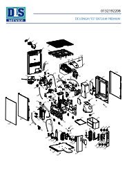
1. GENERAL DESCRIPTION<br />
1 Opening for decaffeinated coffee/for washing tabets<br />
2 Coffee grinder hopper<br />
3 Opening for washing tabs<br />
4 Inspection door<br />
5 Programming key<br />
6 Steam dispensing knob<br />
7 Steam dispensing wand<br />
8 Hot water dispensing spout<br />
1<br />
15<br />
14<br />
13<br />
model AK<br />
1<br />
15<br />
14<br />
13<br />
2 3<br />
12<br />
17<br />
16<br />
10<br />
16<br />
2<br />
12<br />
4<br />
6<br />
english<br />
5<br />
6<br />
7<br />
8<br />
18<br />
11<br />
9 Pressure gauge<br />
10 Coffee grouts box<br />
11 Coffee spouts<br />
model AKC<br />
12 Main switch for turning on machine<br />
13 Feet<br />
14 Function control touch pads<br />
15 Display<br />
10<br />
16 Milk + coffee delivery spout.<br />
17 Autosteamer nozzle<br />
18 Smart Card reader<br />
9<br />
4<br />
8<br />
7<br />
5<br />
6
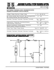
2. TECHNICAL FEATURES<br />
Width (L)<br />
Depth (P)<br />
Height (H)<br />
Weight<br />
Voltage<br />
Total input<br />
Boiler heating<br />
element power<br />
Coffee grinder<br />
motor power<br />
Pump motor<br />
power<br />
Group heating<br />
element power<br />
Piston heating<br />
element power<br />
3. DESCRIPTION OF INTERNAL COMPONENTS<br />
1. Left dispensing group<br />
2. Left coffee-grinder<br />
3. Right coffee-grinder<br />
4. Right dispensing group<br />
5. Volumetric doser<br />
6. Pressure gauge<br />
7. Motor pump<br />
8. Drainage trough<br />
9. Electronic card<br />
10. Main switch<br />
11. Boiler<br />
12. Boiler heating element<br />
13. Pressure switch<br />
57 cm<br />
59 cm<br />
83 cm<br />
94 kg<br />
230/240/400 V<br />
4000 W<br />
(18 A)<br />
2700 W<br />
(12 A)<br />
350 W x 2<br />
(1,5 A)<br />
260 W<br />
(1,2 A)<br />
150 W x 2<br />
(0,8 A)<br />
10 W x 2<br />
(24 V)<br />
1<br />
13<br />
5<br />
12<br />
2<br />
7<br />
english<br />
H<br />
11<br />
Boiler capacity<br />
Boiler working<br />
pressure<br />
Pressure of<br />
water supplied<br />
Pressure of<br />
dispensed coffee<br />
Safety valve<br />
calibration<br />
3<br />
10<br />
P<br />
4<br />
Technical manual<br />
L<br />
7 litres<br />
0,9 - 1,1 bar<br />
0 - 5 bar<br />
8 - 9 bar<br />
2 bar<br />
9<br />
5<br />
6<br />
7<br />
8<br />
TECHNICAL FEATURES - chap.2-3
INSTALLATION - chap.4<br />
Technical manual<br />
4. INSTALLATION<br />
4.1 Unpacking<br />
For correct unpacking proceed as follows to unpack the machine<br />
correctly:<br />
1) Cut the straps around the packaging.<br />
2) Pull the box off upwards.<br />
3) Position the machine on the worktop.<br />
We recommend you keep the packaging until the<br />
guarantee period has expired.<br />
4.2 Preparation of the coffee-grinder<br />
Fit the coffee hoppers in place on the two grinders.<br />
4.3 Positioning the machine<br />
There has to be plenty of room for the appliance and for<br />
using it correctly.<br />
Prepare the counter where the machine will be placed<br />
and make sure it can bear its weight.<br />
It is important that all the terminals of the connections<br />
to the electricity and to the water mains are easy to reach<br />
and in the immediate vicinity of the machine.<br />
To work properly the machine has to stand<br />
on a perfectly level surface.<br />
Any corrections needed to level the machine<br />
can be done by adjusting the feet.<br />
8<br />
english
5. CONNECTIONS and OPERATIONS<br />
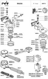
5.1 Hydraulic connection<br />
9<br />
english<br />
Technical manual<br />
The softener provided has been designed to function at a pressure ranging between 1 and 9 bar. It has to be filled<br />
with cold drinking water only.<br />
When connecting the machine to the water mains, install a tap between the machine and the mains so as to be able<br />
to interrupt the supply of water to the appliance.<br />
To prevent the water from freezing, install the softener in a room where the temperature is higher than 0°C.<br />
Before connecting the pipes remove any rubber plugs from the softener tap couplings. To connect proceed as<br />
follows:<br />
1) connect the water mains (1) to the softener inlet (2) using the flexible pipe provided;<br />
2) before connecting the outlet of the softener to the machine, rinse the resins of the softener and check that the water,<br />
which originally may be yellowish, is once again clear;<br />
3) connect the softener outlet (3) to the machine<br />
(4);<br />
4) connect the machine drainage trough (5)<br />
to the drain (6) using the specific pipe provided,<br />
paying attention to avoid sharp bends<br />
or throttlings and keeping it slanted enough<br />
for the waste water to drain away;<br />
5) the drain (6) has to connected to an inspectionable<br />
trap (7) that can be cleaned regularly<br />
to prevent the reflux of bad smells.<br />
7 6 5<br />
To prevent damage of the outer case, valves and taps, install the softener where it is protected<br />
against accidental knocks.<br />
4<br />
1<br />
3<br />
2<br />
CONNECTIONS and OPERATIONS - chap.5
CONNECTIONS and OPERATIONS - chap.5<br />
Technical manual<br />
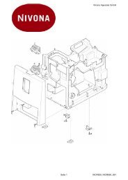
5.2 Maintenance and cleaning<br />
To make the service and cleaning<br />
operations easier, parts of the external casing<br />
are removable.<br />
In particular from the front, the user has<br />
access to the inside of the machine by opening<br />
the doors that cover the group and push button<br />
panel.<br />
5.3 Electrical connections<br />
Connect the cable going from the machine to<br />
the electrical network;<br />
Install a circuit breaker (1).<br />
Effect the electrical connections with the mains voltage disconnected.<br />
10<br />
english
MONOFASE SINGLE-PHASE 230V 230V<br />
+ TERRA + EARTH<br />
NE<br />
C N F<br />
TRIFASE THREE-PHASE 230V 230V<br />
+ TERRA + EARTH<br />
C<br />
TRIFASE THREE-PHASE 400V 400V<br />
+ + NEUTRO NEUTRAL<br />
+ TERRA + EARTH<br />
C<br />
MA<br />
NE<br />
BL<br />
GV<br />
MA<br />
NE<br />
NE<br />
BL<br />
GV<br />
MA<br />
NE<br />
NE<br />
BL<br />
GV<br />
D<br />
R<br />
S<br />
T<br />
R<br />
S<br />
T<br />
N<br />
F<br />
F<br />
11<br />
english<br />
LEGEND<br />
MA Brown<br />
Ne Black<br />
BL Blue<br />
GV Yellow-Green<br />
C Machine cable<br />
F Electricity mains<br />
R-S-T Phase<br />
D Phase<br />
N Neutral<br />
Earth<br />
Technical manual<br />
CONNECTIONS and OPERATIONS - chap.5
CONNECTIONS and OPERATIONS - chap.5<br />
Technical manual<br />
5.4 Machine start-up<br />
Once the machine has been correctly connected to the electrical mains, it is started by placing the<br />
bi-polar switch on the left side of the machine in position 1.<br />
Once this is done, the display will illuminate, and the message "PRESS START" will appear.<br />
In this situation the machine will not be activated, the boiler heating element, and the controls will not be enabled.<br />
By pressing the key on the right of the display push button panel, all machine functions will be activated.<br />
At start-up, after the boiler has been filled, the machine will show the message "PLEASE WAIT". This means that<br />
both groups have not reached the correct working temperature. Upon reaching this temperature, the machine will run<br />
a cycle for both groups and the will show the message "SELECT".<br />
With groups completely cold, warm-up time is about 20 minutes.<br />
Before making selections, for good product quality check boiler pressure via the gauge on the front of the machine<br />
(operating pressure 0.8 –1.2 ) bar)<br />
To bring the machine up to operating capacity without waiting the required time for warm-up, proceed as follows:<br />
Place the programming key in the ON position. Start the machine, first with the main switch, then by pressing ON.<br />
The machine will show the message on the display "PLEASE WAIT".<br />
Press the ENTER key . The machine will perform a dry run of the delivery groups, and then it will go to<br />
"SELECT".<br />
The machine will be ready for operation, and the technician may perform all required operations.<br />
For good quality of delivered product, wait for proper heating of groups and of the water in the boiler<br />
(approx.25 minutes).<br />
5.5 Adjustment of the pump<br />
Switch the machine on as explained in the user manual.<br />
Effect several automatic washing cycles and check the correct working<br />
pressure on the gauge (8 - 9 bar).<br />
If necessary, calibrate pressure by means of the by-pass adjustment<br />
screw (1) on the pump.<br />
12<br />
english<br />
1
6. <strong>MACHINE</strong> PROGRAMMING<br />
13<br />
english<br />
Technical manual<br />
This chapter lists the instructions for modifying some machine parameters, such as group temperatures, grinding<br />
times, dose adjustment, and so on.<br />
The procedures are also described for checking for defective components, for counting selections made, for setting<br />
wash requests, and so forth.<br />
To access the programming menu, do the following:<br />
Turn the programming key clockwise. This key is located on the right of the control panel. The display will show the<br />
letter "P", to indicate that the machine can be programmed.<br />
Once the letter P shows on the display, press and hold the MODE key for about five seconds until the display<br />
shows the message "PROGRAMME GRINDING".<br />
Press the MODE key and it will be possible to scroll through all the various programming menus. Press the<br />
ENTER key and it will be possible to enter each sub-menu, and via the ARROW , keys, to modify the<br />
selected parameters.<br />
program. grinding<br />
GRINDING TIMES, T° GROUPS, NO. GROUNDS, COMPRESSION STRENGTH (page14)<br />
opt. add. hot wat. ADDED WATER OPTION (page 18)<br />
PROGram DOSes. <strong>COFFEE</strong> DOSES (page 18)<br />
program date<br />
water level<br />
in the boiler<br />
test iNput<br />
program test<br />
readout data COUNT OF SELECTIONS (page 30) WITHOUT STAFF KEY<br />
revert data<br />
to zero<br />
programming<br />
wash cap.<br />
programming<br />
wash groups<br />
AUTOSTEAMER TEMPERATURE (optional) (page 15)<br />
MILK, TEA DOSES (page 19)<br />
dose modificat. CORRECTION OF <strong>COFFEE</strong> DOSE (page 20)<br />
CORRECTION OF MILK, TEA DOSE (page 21)<br />
DATE, HOUR, MINUTES, SECONDS (page 22)<br />
<strong>MACHINE</strong> ALARMS COUNTING (page 23)<br />
INPUT SIGNALS CONTROL (page 25)<br />
WITHOUT ADDED WATER<br />
WITH ADDED WATER<br />
DOSES OF CAPPUCCINO, MILK AND <strong>COFFEE</strong>, MILK WITH SHOT OF <strong>COFFEE</strong> (opt.) (page 19)<br />
CHECK OF INTERNAL ELECTRICAL COMPONENTS (page 28)<br />
ZERO SETTING OF SELECTIONS COUNT (page 32)<br />
OHNE WASSERBEIGABE<br />
MIT WASSERBEIGABE<br />
ADJUST.OF AMOUNTS OF CAPPUC. MILK AND <strong>COFFEE</strong>, MILK WITH SHOT OF <strong>COFFEE</strong> (opt.) (page 21)<br />
ZERO SETTING (page 24)<br />
WITH STAFF KEY<br />
PROGRAMMING OF CAPPUCCINO MAKER WATER REQUEST YES/NO (page32)<br />
PROGRAMMING OF GROUPS WASHING REQUEST YES/NO (page32)<br />
PROGRAMMING - chap.6
PROGRAMMING - chap.6<br />
Technical manual<br />
6.1 Programming of grinding times<br />
Programming of grinding times is for the purpose of changing the amount of grams of coffee for each selection in<br />
which coffee is used.<br />
This modification is performed by changing the grinding time for each coffee selection.<br />
To modify grinding times, proceed as follows:<br />
Turn the programming key clockwise. This key is located on the right of the control panel. The display will show the<br />
letter "P", to indicate that the machine can be programmed.<br />
Press and hold the MODE key for about five seconds until the display shows the message "PROGRAMME<br />
GRINDING".<br />
Press the ENTER key , and the machine will show the time that has been set for each selection, in succession:<br />
key 1, key 2, key 3...key 24.<br />
K1<br />
K6<br />
K2<br />
1 2 3 4 5 11 12<br />
6 7 8 9 10 13 14<br />
K7<br />
K3<br />
K8<br />
K4<br />
K9<br />
K5<br />
K10<br />
K11<br />
K13<br />
K12<br />
K14<br />
In this section, the machine will show only a list of keys to which a beverage has been matched that uses the coffee<br />
beans in the hopper.<br />
For example, if key number 2 is matched with the MILK selection (see "Push button panel configuration", chap.<br />
7.12) and hence coffee is not used, in grinding programming press the ENTER key and the machine will show<br />
the grinding time associated with key 1 before skipping directly to key 3 (provided this key is matched with a beverage<br />
with the aforementioned characteristics).<br />
Use the ARROW keys to increase or decrease grinding time of each selection expressed in seconds or<br />
tenths of seconds.<br />
GRINDING TIMES TABLE (sec.)<br />
Single Double<br />
Medium-coarse grinding 2,4 2,8<br />
Fine grinding. 2,7 3,2<br />
Grinding times may not always correspond to a constant weight, and may change depending on the type of<br />
coffee, the wear of the grinders or the diameter of grinding. Therefore the coffee grinder will grind a different<br />
dose (give or take a few grams).<br />
To exit programming, repeatedly press the MODE key until the display show the message "SELECT".<br />
14<br />
english<br />
K15<br />
K19<br />
K16<br />
15 16 17 18 24<br />
19 20 21 22 23<br />
K20<br />
K17<br />
K21<br />
K18<br />
K22<br />
K24<br />
K23
6.2 Programming of group temperatures<br />
15<br />
english<br />
Technical manual<br />
In this section it is possible to modify the temperature of each group. In fact, each group is heated by an internal<br />
heating element controlled by a temperature sensor. This operation may be necessary when the coffee delivered is not<br />
at a temperature which is satisfactory to the client.<br />
To adjust the temperature, proceed as follows:<br />
Turn the programming key clockwise. This key is located on the right of the control panel. The display will show the<br />
letter "P", to indicate that the machine can be programmed.<br />
Press and hold the MODE key for about five seconds until the display shows the message "PROGRAMME<br />
GRINDING".<br />
Press the ENTER key until the display shows the message "PROG. GRINDING".<br />
Press the MODE key until the display shows the message "PROG. GR. TEMPERATURE 1".<br />
To modify the temperature of group 1, press the ENTER key again and the display will show the message<br />
"PROG. GR. 1 TEMPERATURE". Press the ENTER key again, to adjust group 2.<br />
Once you have selected the group for which you want to change the temperature via the ARROW keys ,<br />
set the desired temperature.<br />
Standard operating temperature inclusive between 80°C and 92°C.<br />
To exit programming, repeatedly press the MODE key until the display show the message "SELECT".<br />
6.3 Programming of Autosteamer temperature (if configured)<br />
In this section it is possible to modify the temperature of the automatic steam (Autosteamer)<br />
This programming option will be visible and modifiable only if the software has been configured for the use of this<br />
device (optional).<br />
To set the temperature, proceed as follows:<br />
Turn the programming key clockwise. This key is located on the right of the control panel. The display will show the<br />
letter "P", to indicate that the machine can be programmed.<br />
Once the letter P shows on the display, press and hold the MODE key for about five seconds until the display<br />
shows the message "PROGRAMME GRINDING".<br />
Press the ENTER key the message appears "PROG. STEAM TEMPERATURE".<br />
Use the ARROW keys to modify the temperature value.<br />
Once the temperature is set, press the proper key. The machine will stop delivering steam once the beverage reaches<br />
the set temperature.<br />
The actual temperature of the beverage heated by the automatic steam system may differ by a few degrees<br />
depending on the amount of product heated.<br />
PROGRAMMING - chap.6
PROGRAMMING - chap.6<br />
Technical manual<br />
6.4 Programming grounds no.<br />
This programming operation allows you to change the maximum number of coffee grounds tabs that can be discarded<br />
into the grounds drawer. Once this number has been reached, the machine will inform the operator to empty the grounds<br />
drawer via the procedure shown in the user's manual of the machine.<br />
To modify this value, proceed as follows:<br />
Turn the programming key clockwise. This key is located on the right of the control panel. The display will show the<br />
letter "P", to indicate that the machine can be programmed.<br />
Once the letter P shows on the display, press and hold the MODE key for about five seconds until the display<br />
shows the message "PROGRAMME GRINDING".<br />
Press the ENTER key until the display show the message "PROG. GROUNDS".<br />
Use the ARROW keys to modify the maximum amount of grounds that can be discarded into the drawer.<br />
If the machine uses direct grounds discharge (without drawer), and the user does not wish to be informed that the<br />
drawer is full, the aforementioned value will need to be set to 0. In this case the machine will never signal the need to<br />
empty the grounds drawer.<br />
To exit programming, repeatedly press the MODE key until the display show the message "SELECT".<br />
6.5 Programming piston compression<br />
This menu lets you modify the pressure that the upper piston uses to press the coffee during the pressure phase<br />
that precedes delivery.<br />
By increasing the value shown in this section of the display, the machine will compress the coffee with greater force.<br />
On the contrary, decreasing this value decreases the compression force on the coffee.<br />
The machine identifies four categories of beverage for which it is possible to modify the force of compression:<br />
To modify this value, proceed as follows:<br />
Single dose group 1 "PROG. COMP. S GR.1"<br />
Double dose group 1 "PROG. COMP. D GR.1"<br />
Single dose group 2 "PROG. COMP. S GR.2"<br />
Doppia dose gruppo 2 "PROG. COMP. D GR.2"<br />
Turn the programming key clockwise. This key is located on the right of the control panel. The display will show the<br />
letter "P", to indicate that the machine can be programmed.<br />
Once the letter "P" shows on the display, press and hold the MODE key for about five seconds until the display<br />
shows the message "PROGRAMME GRINDING".<br />
Press the ENTER key until the display show the message "PROG. COMPRESSION S GR. 1".<br />
Press the ENTER key to select one of the four categories of beverage.<br />
Use the ARROW keys to modify the compression value of the piston (min 80 max 110) for each of the<br />
categories.<br />
The milk and coffee, cappuccino and milk with a shot of coffee selections are to be considered as part of the group 1 single<br />
dose coffee categories if made with the left-hand keypad, group 2 single dose coffee if made with the right-hand keypad.<br />
To exit programming, repeatedly press the MODE key until the display show the message "SELECT".<br />
16<br />
english
6.6 Loading/saving data on Smart Card<br />
The machine is standard equipped with a Smart Card reader.<br />
This makes it possible to save all data programmed by the user in a card with a microchip. This data can subsequently<br />
be re-loaded in the same machine or in another of the same model.<br />
To do this, proceed as follows:<br />
1. Saving data on Smart Card<br />
Insert the provided Smart Card with the CMA logo facing up.<br />
Turn the programming key clockwise. The display will show the letter "P".<br />
Hold down the MODE key until the display show the message "PROG. GRINDING".<br />
Press the ENTER key until the display shows the message "UPLOAD TO SMART CARD".<br />
Hold down the ENTER key (the display will show the message "UPLOADING") until the display shows the<br />
message "UPLOAD TO SMART CARD".<br />
At this point, all data set on the machine (doses, temperature, grinding times, key configuration, etc.) will be saved<br />
in the memory cell of the Smart Card.<br />
To exit programming, repeatedly press the MODE key until the display show the message "SELECT".<br />
2. Download of data from Smart Card<br />
Insert the provided Smart Card with the CMA logo facing up.<br />
Turn the programming key clockwise. The display will show the letter "P".<br />
Hold down the MODE key until the display show the message "PROG. GRINDING".<br />
Press the ENTER key until the display shows the message "DOWNLOAD FROM SMART CARD".<br />
Hold down the ENTER key (the display will show the message "DOWNLOADING") until the display shows<br />
the message "DOWNLOAD FROM SMART CARD".<br />
At this point, all data previously saved on the Smart Card in question will be loaded into the internal memory of the<br />
machine, which will be fully configured with the data downloaded from the Smart Card (group temperatures, doses,<br />
key configurations and so on).<br />
To exit programming, repeatedly press the MODE key until the display show the message "SELECT".<br />
17<br />
english<br />
Technical manual<br />
PROGRAMMING - chap.6
PROGRAMMING - chap.6<br />
Technical manual<br />
6.7 Added water option<br />
The added water option makes it possible choose to which coffee selections a certain programmable amount of hot<br />
water will be added.<br />
This option is available in the medium single and double selections, and single and double long (American coffee)<br />
selections of both groups.<br />
To activate this option, proceed as follows:<br />
Turn the programming key clockwise. This key is located on the right of the control panel. The display will show the<br />
letter P, to indicate that the machine can be programmed.<br />
Once the letter P shows on the display, press and hold the MODE key for about five seconds until the display<br />
shows the message "PROGRAMME GRINDING".<br />
Press the ENTER key .The display will show the message "ADDED WATER OPTION".<br />
Press the ENTER key to select one of the categories where this option can be activated. Then use the AR-<br />
ROW keys to activate it (S) or de-activate it (N).<br />
To exit programming, repeatedly press the MODE key until the display show the message "SELECT".<br />
6.8 Programming doses<br />
This function makes it possible to program the amount of product in the cup of the selections delivered by the machine<br />
(coffee, milk, tea, cappuccino and so forth).<br />
Programming must be carried out on all enabled keys, even if the same beverage (coffee, cappuccino, etc.) has<br />
been assigned to more than one key (see "Push button panel configuration" chap.7.12).<br />
To modify the dose of the selection, follow this procedure:<br />
Turn the programming key clockwise. This key is located on the right of the control panel. The display will show the<br />
letter "P", to indicate that the machine can be programmed.<br />
Once the letter P shows on the display, press and hold the MODE key for about five seconds until the display<br />
shows the message "PROGRAMME GRINDING".<br />
Press the MODE key until the display shows the message "PROG. DOSES"<br />
Depending on the type of beverage selected, refer to one of the points mentioned below.<br />
1. <strong>COFFEE</strong> SELECTIONS PROGRAMMING (with no added water)<br />
Press the key of the desired selection to activate the grinding and delivery cycle.<br />
Once the desired dose of coffee has been reached, press the same key again to stop programming.<br />
Re-programming is possible at any time by repeating the procedure described above.<br />
During programming, if the programming of the coffee dose is stopped using the STOP key , the machine<br />
will not memorize the dose that has just been memorized but instead will retain in memory the last dose previously<br />
memorized.<br />
2. <strong>COFFEE</strong> SELECTIONS PROGRAMMING (with added water)<br />
Press the key of the desired selection to activate the grinding and delivery cycle.<br />
Once the desired amount of coffee is reached, press the same key again and the machine will stop delivering coffee<br />
and it will automatically start delivering water. Once the desired amount of water is reached, press the selection key<br />
again to stop delivery.<br />
In this way the machine will have memorized both the amount of coffee and the amount of hot water (added water).<br />
Re-programming is possible at any time by repeating the procedure described above.<br />
18<br />
english
3. PROGRAMMING <strong>COFFEE</strong> AND MILK / CAPPUCCINO SELECTIONS<br />
By pressing the key for the desired selection, the phase of milk suction and heating by the cappuccino maker will<br />
be started. Once the desired dose of milk is reached, press the same key again. The machine will stop milk delivery,<br />
and it will memorize the time required for the suction of that amount. It will also activate the coffee grinding and delivery<br />
cycle. Once the desired dose of coffee is reached, press the same key again. The machine will stop delivery of coffee<br />
and it will memorize the amount reached.<br />
4. PROGRAMMING OF MILK DOSES AND FOAMED MILK<br />
By pressing the key for the desired selection, the phase of milk suction and heating by the cappuccino maker will be<br />
started. Once the desired dose of milk is reached, press the same key again. The machine will stop milk delivery, and<br />
it will memorize the time required for the suction of that amount.<br />
5. PROGRAMMING DOSES OF HOT WATER<br />
Pressing the hot water selection key will activate the solenoid valve for tea delivery. Once the desired dose is reached,<br />
press the same key again.<br />
The machine will stop delivery and it will memorize the time required for delivery. The dose can be re-defined at<br />
any time.<br />
By changing the amount of cold water mixed with the hot water, the amount of water delivered changes as well.<br />
Before programming it is therefore advisable to determine the correct temperature of the hot water.<br />
6- STEAM TIME PROGRAMMING (optional)<br />
By pressing the steam key (if present), machine will activate the solenoid valve, and steam delivery will begin.<br />
By pressing the same key again, the machine will stop delivery and it will memorize the time required for delivery.<br />
The operation can be repeated at any time.<br />
7. PROGRAMMING DOSES OF MILK WITH A SHOT OF <strong>COFFEE</strong> (LCL)<br />
a) Cold milk with shot of coffee<br />
Press the key for the selection of cold milk with a shot of coffee. The display will show the message<br />
"PROG. MILK WITH SHOT OF <strong>COFFEE</strong> F.".<br />
Cold milk delivery will begin.<br />
Once the desired dose has been reached, press the same key again. The machine will stop delivery of cold milk,<br />
memorize the time required for delivery and will automatically start delivery of hot foamed milk. Upon completing the<br />
dose of hot foamed milk, press the same key again, and the machine will stop and memorize delivery. The coffee cycle<br />
will start automatically. Once the desired dose of coffee is reached, press the same key again. The machine will stop<br />
coffee delivery and programming of cold milk with a shot of coffee will be complete.<br />
Programming can be repeated at any time by following the procedure indicated above.<br />
Latte macchiato<br />
Cool<br />
Dispensing<br />
Cold Milk<br />
Latte macchiato<br />
Cool<br />
Dispensing<br />
Hot milk<br />
foamed<br />
19<br />
english<br />
Latte macchiato<br />
Cool<br />
Dispensing<br />
Coffee<br />
Latte macchiato<br />
Cool<br />
Technical manual<br />
Progr.<br />
performed<br />
PROGRAMMING - chap.6
PROGRAMMING - chap.6<br />
Technical manual<br />
b) Hot milk with a shot of coffee<br />
Press the key for the selection of hot milk with a shot of coffee. The display will show the message<br />
"PROG. MILK WITH SHOT OF <strong>COFFEE</strong> C." and delivery will begin of non-foamed hot milk.<br />
Once the desired dose is reached, press the same key. Delivery of non-foamed milk will stop, the machine will<br />
memorize the time required and delivery of hot foamed milk will start automatically. Once the desired dose is reached,<br />
press the key referred to above. A pause will be activated.<br />
Once the desired pause time has elapsed, press the same key again and coffee delivery will start. Once the desired<br />
amount of coffee is reached, press the same key again to stop delivery and memorize the dose.<br />
Programming can be repeated at any time by following the procedure indicated above.<br />
Latte macchiato<br />
Warm<br />
Dispensing<br />
Hot milk<br />
Latte macchiato<br />
Warm<br />
All decaf doses will automatically assume the value of the corresponding non-decaf dose, and will not be<br />
programmable separately.<br />
E.g. 1 <strong>ESPRESSO</strong> DECAF GR1 will have the same dose as 1 <strong>ESPRESSO</strong> GR.1 .<br />
By modifying the dose of the espresso gr.1 you will also automatically modify the dose of espresso decaf<br />
gr.1 in the same way.<br />
6.9 Adjustment of doses<br />
Dispensing<br />
Hot milk<br />
foamed<br />
In this section of programming it is possible to modify the previously established dose, without re-programming, but<br />
modifying the amount of water used by the machine for each coffee selection or modifying the time memorized by the<br />
machine for each delivery of milk, hot water, etc.<br />
To modify dose parameters, proceed as follows:<br />
Latte macchiato<br />
Turn the programming key clockwise. This key is located on the right of the control panel. The display will show the<br />
letter "P", to indicate that the machine can be programmed.<br />
Once the letter "P" shows on the display, press and hold the MODE key for about five seconds until the display<br />
shows the message "PROGRAMME GRINDING."<br />
Press the MODE key until the display shows the message "DOSE ADJUSTMENT"<br />
Press the key assigned to the selection for which you want to adjust or modify the dose.<br />
If the selection is a coffee without added water, proceed as follows:<br />
Press the key for the selection of which you wish to modify the dose. The display will show the volume of water in<br />
c.c. calculated by the volumetric dosing device for that particular selection. E.g. "C. DOSE 1 <strong>ESPRESSO</strong> GR1 CC<br />
NNN".<br />
Use the ARROW keys to modify the amount of water used for the specific selection.<br />
Warm<br />
To memorize the modified dose, press ENTER .<br />
pause<br />
If the selection is a coffee with added water, proceed as follows:<br />
20<br />
english<br />
Latte macchiato<br />
Warm<br />
Dispensing<br />
Coffee<br />
Latte macchiato<br />
Warm<br />
PROGR.<br />
performed
Press the key for the selection of which you wish to modify the dose. The display will show the volume of water in<br />
c.c. calculated by the volumetric dosing device for that particular selection. E.g. "C. DOSE 1 <strong>ESPRESSO</strong> GR1 CC<br />
NNN".<br />
Use the ARROW keys to modify the amount of water used for that specific selection.<br />
To memorize the modified dose of coffee, press ENTER . Once the new dose of dose of coffee is confirmed,<br />
the display will show the amount of water used for the dose of added water.<br />
Use the ARROW keys to modify the dose. To confirm the newly set dose, press ENTER .<br />
If the selection to be modified is a milk or hot water selection, proceed as follows:<br />
Press the key for the selection whose dose you want to modify. The display will show delivery time expressed in<br />
seconds and tenths of a second.<br />
Use the ARROW keys to modify the delivery time shown on the display.<br />
To confirm the newly set time press the ENTER key .<br />
If the selection is coffee with milk or cappuccino, proceed as follows:<br />
Press the key for the selection of which you wish to modify the dose. The display will show the volume of water in<br />
c.c. calculated by the volumetric dosing device for that particular selection.<br />
Use the ARROW keys to modify this value as desired<br />
Press the ENTER key , and the machine will memorize the previously set new value. It will show the time on<br />
the display, in seconds and tenths of seconds, for milk display.<br />
Use the ARROW keys to modify this time as necessary.To confirm the modification press ENTER .<br />
If the selection is cold milk with a shot of coffee, proceed as follows:<br />
Press the key for the selection whose dose you want to modify. The display will show delivery time for the cold milk<br />
expressed in seconds and tenths of a second. "MOD. DOSE MILK F".<br />
Use the ARROW keys to modify this value as desired<br />
Press the ENTER key to confirm and to go automatically to modification of the amount of water calculated by<br />
the dosing device in cc for the dose of coffee "M. DOSE <strong>COFFEE</strong> NN".<br />
Use the ARROW keys to modify this value as desired<br />
Press the ENTER key to confirm and to go automatically to control of the dose of hot foamed milk expressed<br />
in seconds and tenths of a second "M. DOSE MILK F".<br />
Use the ARROW keys to modify this value as desired<br />
Press the ENTER key to confirm.<br />
If the selection is hot milk with a shot of coffee, proceed as follows:<br />
Press the key for the selection whose dose you want to modify. The display will show delivery time for the hot foamed<br />
milk (first delivery) expressed in seconds and tenths of a second. "MOD. DOSE MILK C".<br />
Use the ARROW keys to modify this value as desired<br />
Press the ENTER key to confirm and to go automatically to modification of the pause between two deliveries<br />
of hot milk, expressed in seconds and tenths of one second "MOD. PAUSE".<br />
Use the ARROW keys to modify this value as desired<br />
Press the ENTER key to confirm and to go automatically to the modification of the delivery time of hot foamed<br />
milk (2nd delivery).<br />
Use the ARROW keys to modify this value as desired<br />
Press the ENTER key to confirm and to go automatically to modification of the amount of water calculated by<br />
the dosing device in cc for the dose of coffee "M. DOSE coffee NN".<br />
Use the ARROW keys to modify this value as desired<br />
Press the ENTER key to confirm.<br />
21<br />
english<br />
Technical manual<br />
PROGRAMMING - chap.6
PROGRAMMING - chap.6<br />
Technical manual<br />
6.10 Programming date<br />
In this section it is possible to update and modify the date in the machine (year, month, day and time).<br />
To modify one of the date parameters, proceed as follows:<br />
Turn the programming key clockwise. This key is located on the right of the control panel. The display will show the<br />
letter "P", to indicate that the machine can be programmed.<br />
Once the letter "P" shows on the display, press and hold the MODE key for about five seconds until the display<br />
shows the message "PROGRAMME GRINDING".<br />
Press the MODE key until the display shows the message "DATE PROGRAMMING"<br />
Press the ENTER key to select the parameter to be modified and use the ARROW keys to modify<br />
the parameters.<br />
To exit programming, repeatedly press the MODE key until the display show the message "SELECT".<br />
1<br />
2<br />
3<br />
4<br />
5<br />
6<br />
7<br />
PROGRAM date<br />
year XX<br />
+<br />
PROGRAM date<br />
Month XX<br />
PROGRAM date<br />
day XX<br />
PROGRAM date<br />
weekday XXXXXXXX<br />
+<br />
PROGRAM date<br />
hourS XX<br />
PROGRAM date<br />
MINUTes XX<br />
PROGRAM date<br />
SECONDS XX<br />
+<br />
22<br />
english
6.11 Alarm signals<br />
23<br />
english<br />
Technical manual<br />
In this section it is possible to check all signals that the machine provides in the event of a malfunction.<br />
The machine will record every single alarm in a register (group motor blocked, group overheat, coffee missing alarm,<br />
etc.). This register can be consulted and reset as necessary.<br />
To check every single item, proceed as follows:<br />
Turn the programming key clockwise. This key is located on the right of the control panel. The display will show the<br />
letter "P", to indicate that the machine can be programmed.<br />
Once the letter "P" shows on the display, press and hold the MODE key for about five seconds until the display<br />
shows the message "PROGRAMME GRINDING".<br />
Press the MODE key until the display shows the message "LEVEL OF WATER IN BOILER".<br />
Press the ENTER key to display every single malfunction message provided by the machine. The value shown<br />
on the display represents the number of times that event has occurred since the last reset.<br />
To reset the count of every single event, press and hold down the ARROW key until the display shows<br />
"TOT . 0000".<br />
1<br />
2<br />
3<br />
4<br />
5<br />
6<br />
7<br />
8<br />
9<br />
water level<br />
IN the boiler nn<br />
minimum level<br />
IN the boiler nn<br />
boiler sensor<br />
not active nn<br />
piston motor gr.1<br />
BLOCked nn<br />
not coffee<br />
GROUP 1 nn<br />
volum doser GR.1<br />
does not count nn<br />
nsufficient GR 1<br />
compression nn<br />
over temperature<br />
GRoUP 1 nn<br />
MICRO<br />
COMPRESSION GR.1 nn<br />
grinding GR 1<br />
NOt correct nn<br />
piston motor gr.2<br />
BLOCked nn<br />
not coffee<br />
GROUP 2 nn<br />
volum doser GR.2<br />
does not count nn<br />
insufficient GR 2<br />
compression nn<br />
over temperature<br />
GRoUP 2 nn<br />
MICRO<br />
COMPRESSION GR.2 nn<br />
grinding GR 2<br />
NOt correct nn<br />
To exit programming, repeatedly press the MODE key until the display show the message "SELECT".<br />
10<br />
11<br />
12<br />
13<br />
14<br />
15<br />
16<br />
17<br />
PROGRAMMING - chap.6
PROGRAMMING - chap.6<br />
Technical manual<br />
1<br />
2<br />
3<br />
4<br />
5<br />
6<br />
7<br />
8<br />
9<br />
10<br />
from<br />
11<br />
to<br />
17<br />
control machine alarms<br />
Display of the NN number of alarms due to maximum boiler<br />
filling time being exceeded.<br />
Press ENTER to go to the next check.<br />
Display of the NN number of alarms due to minimum level of<br />
water in the boiler.<br />
Press ENTER to go to the next check.<br />
Display of the NN number of alarms due to the boiler sensor<br />
not working.<br />
Press ENTER to go to the next check.<br />
Display of the NN number of alarms due to blockage of the<br />
group 1 piston.<br />
Press ENTER to go to the next check.<br />
Display of the NN number of alarms due to the lack of coffee<br />
in group 1.<br />
Press ENTER to go to the next check.<br />
Display of the NN number of alarms due to the volumetric<br />
counter of group 1 not working.<br />
Press ENTER to go to the next check.<br />
Display of the NN number of alarms due to insufficient<br />
compression of group 1.<br />
Press ENTER to go to the next check.<br />
Display of the NN number of alarms due to overtemperature<br />
of group 1.<br />
Press ENTER to go to the next check.<br />
Display of the NN number of alarms due to the group 1<br />
compression microswitch.<br />
Press ENTER to go to the next check.<br />
Display of the NN number of alarms due to non-conforming<br />
grinding of group 1.<br />
Press ENTER to go to the next check.<br />
To check group 2 alarms, proceed in the same way as described<br />
above.<br />
zero setting of the alarms<br />
24<br />
english<br />
minimum level<br />
IN the boiler nn<br />
boiler sensor<br />
not active nn<br />
piston motor gr.1<br />
BLOCked nn<br />
not coffee<br />
GROUP 1 nn<br />
volum doser GR.1<br />
does not count nn<br />
insufficient GR 1<br />
compression nn<br />
over temperature<br />
GRoUP 1 nn<br />
MICRO<br />
COMPRESSION GR.1 nn<br />
grinding GR 1<br />
NOt correct nn<br />
c.t. .................. erog. s. GR nnn 2<br />
.......................... NN<br />
While each alarm is displayed it is possible to revert to zero the relative number by keeping the ARROW key<br />
pressed for at least 5 seconds until the message is displayed (example)<br />
water level<br />
in the boiler<br />
TOT. 0000<br />
water level<br />
IN the boiler nn
6.12 Input test<br />
25<br />
english<br />
Technical manual<br />
In this section it is possible to check the operation of all input signals of the machine such as push button panel keys,<br />
microswitches, probes, and so forth.<br />
To carry out this check proceed as follows:<br />
Turn the programming key clockwise. This key is located on the right of the control panel. The display will show the<br />
letter "P", to indicate that the machine can be programmed.<br />
Once the letter P shows on the display, press and hold the MODE key for about five seconds until the display<br />
shows the message "PROGRAMME GRINDING".<br />
Press the MODE key until the display shows the message "INPUT TEST".<br />
Consult the key and follow the instructions below to check the various input signals.<br />
K1<br />
K6<br />
K2<br />
K1 1 K2 2 K3 3 K4 4 K5 5 K11 11 K12 12<br />
K6 6 K7 7 K8 8 K9 9 K10 10 K13 13 K14 14<br />
K7<br />
K3<br />
K8<br />
K4<br />
K9<br />
only version<br />
with keys<br />
K5<br />
K10<br />
K27 K28<br />
K11<br />
push button panel<br />
K13<br />
K25 Auxiliary<br />
K26 Auxiliary<br />
K29 Micro 1 GR1<br />
K30 Micro 2 GR1<br />
K31 Micro 3 GR1<br />
K32 Micro 1 GR2<br />
K33 Micro 2 GR2<br />
K34 Micro 3 GR2<br />
K35 Grounds drawer micro<br />
K36 Top door micro<br />
K12<br />
K14<br />
K37 Programming key<br />
K38 Water level probe<br />
K39 Minimum level sensor<br />
K40 The waiter’s key (A-D-H-L-N-Q-S-U)<br />
K41 The waiter’s key (B-L-Q-T-V)<br />
K42 The waiter’s key (E-H-K-L-R-S-T-U)<br />
K43 The waiter’s key (M-N-P-Q-R-S-T-U)<br />
K15<br />
K15 15 K16 16 K17 17 K18 18 K24 24<br />
K19 19 K20 20 K21 21 K22 22 K23<br />
23<br />
K19<br />
K16<br />
K20<br />
K17<br />
K21<br />
K18<br />
K22<br />
K24<br />
K23<br />
PROGRAMMING - chap.6
PROGRAMMING - chap.6<br />
Technical manual<br />
1<br />
2<br />
3<br />
4<br />
5<br />
6<br />
7<br />
8<br />
9<br />
10<br />
11<br />
12<br />
13<br />
14<br />
15<br />
TEST InPUT<br />
K 1 0 ---> 1<br />
TEST InPUT<br />
K 2 0 ---> 1<br />
TEST InPUT<br />
K 3 0 ---> 1<br />
TEST InPUT<br />
K 4 0 ---> 1<br />
TEST InPUT<br />
K 5 0 ---> 1<br />
TEST InPUT<br />
K 6 0 ---> 1<br />
TEST InPUT<br />
K 7 0 ---> 1<br />
TEST InPUT<br />
K 8 0 ---> 1<br />
TEST InPUT<br />
K 9 0 ---> 1<br />
TEST InPUT<br />
K 10 0 ---> 1<br />
TEST InPUT<br />
K 11 0 ---> 1<br />
TEST InPUT<br />
K 12 0 ---> 1<br />
TEST InPUT<br />
K 13 0 ---> 1<br />
TEST InPUT<br />
K 14 0 ---> 1<br />
TEST InPUT<br />
K 15 0 ---> 1<br />
16<br />
17<br />
18<br />
19<br />
20<br />
21<br />
22<br />
23<br />
24<br />
25<br />
26<br />
27<br />
28<br />
29<br />
INPUT test<br />
TEST InPUT<br />
K 16 0 ---> 1<br />
TEST InPUT<br />
K 17 0 ---> 1<br />
TEST InPUT<br />
K 18 0 ---> 1<br />
TEST InPUT<br />
K 19 0 ---> 1<br />
TEST InPUT<br />
K 20 0 ---> 1<br />
TEST InPUT<br />
K 21 0 ---> 1<br />
TEST InPUT<br />
K 22 0 ---> 1<br />
TEST InPUT<br />
K 23 0 ---> 1<br />
TEST InPUT<br />
K 24 0 ---> 1<br />
TEST InPUT<br />
K 25 0 ---> 1<br />
TEST InPUT<br />
K 26 0 ---> 1<br />
TEST InPUT<br />
K 27 1 ---> 0<br />
TEST InPUT<br />
K 28 0 ---> 1<br />
TEST InPUT<br />
K 29 0 ---> 1<br />
26<br />
english<br />
30<br />
31<br />
32<br />
33<br />
34<br />
35<br />
36<br />
37<br />
38<br />
39<br />
40<br />
41<br />
42<br />
43<br />
TEST InPUT<br />
K 30 1 ---> 0<br />
TEST InPUT<br />
K 31 0 ---> 1<br />
TEST InPUT<br />
K 32 0 ---> 1<br />
TEST InPUT<br />
K 33 1 ---> 0<br />
TEST InPUT<br />
K 34 1 ---> 0<br />
TEST InPUT<br />
K 35 1 ---> 0<br />
TEST InPUT<br />
K 36 1 ---> 0<br />
TEST InPUT<br />
K 37 1 ---> 0<br />
TEST InPUT<br />
K 38 1 ---> 0<br />
TEST InPUT<br />
K 39 1 ---> 0<br />
TEST InPUT<br />
K 40 0 ---> 1<br />
TEST InPUT<br />
K 41 0 ---> 1<br />
TEST InPUT<br />
K 42 0 ---> 1<br />
TEST InPUT<br />
K 43 0 ---> 1
from<br />
1<br />
to<br />
26<br />
from<br />
27<br />
to<br />
32<br />
33<br />
34<br />
from<br />
36<br />
to<br />
37<br />
from<br />
40<br />
to<br />
43<br />
push button panel control<br />
Keep the selection key pressed (for example 1 <strong>ESPRESSO</strong><br />
coffee). The test is OK if what is shown on the display goes<br />
from 0 to 1.<br />
k .. indicates the push button code (see drawings on page<br />
25. Press ENTER to go to the next check.<br />
group microswitches control<br />
MIKRO GR.1 GR.2<br />
1 K27 K30<br />
2 K28 K31<br />
3 K29 K32<br />
Disconnect the microswitch wire (for example of microswitch<br />
1) and connect it to the central contact of the microswitch.<br />
The test is OK if what is shown on the display goes from 0 to<br />
1 or 1 to 0 depending on the position of the micro.<br />
Press ENTER to go to the next check<br />
grounds drawer control<br />
Open the coffee grounds drawer. The test is OK if the on the display appears:<br />
- 1 with grounds drawer closed<br />
- 0 with grounds drawer open<br />
Press ENTER to go to the next check.<br />
ispection door control<br />
The test is OK if the display shows:<br />
- 1 with door closed<br />
- 0 with door open<br />
Press ENTER to go to the next check.<br />
boiler sensors control<br />
Disconnect either the wire of the water level sensor or of the minimum<br />
level sensor. The test is positive if the following is displayed:<br />
- 1 wire connected to the sensor<br />
- 0 with wire disconnected from the sensor<br />
Press ENTER to go to the next check.<br />
keys control<br />
Put the key in its lock. The test is OK if the on the display appears:<br />
- 1 whit waiters key inserted<br />
- 0 whit waiters key disconnected<br />
Press ENTER to go to the next check.<br />
27<br />
english<br />
Technical manual<br />
TEST InPUT<br />
K 1 0 ---> 1<br />
3<br />
2<br />
TEST InPUT<br />
K 27 0 ---> 1<br />
TEST InPUT<br />
K 33 1 ---> 0<br />
TEST InPUT<br />
K 34 1 ---> 0<br />
TEST InPUT<br />
K 36 0 ---> 1<br />
TEST InPUT<br />
K 40 0 ---> 1<br />
1<br />
PROGRAMMING - chap.6
PROGRAMMING - chap.6<br />
Technical manual<br />
6.13 Actuator test<br />
In this section it is possible to check the electrical operation of all components (utilities) of the machine (grinder motor,<br />
group motor, solenoid valves, etc).<br />
To carry out this check proceed as follows:<br />
Turn the programming key clockwise. This key is located on the right of the control panel. The display will show the<br />
letter "P", to indicate that the machine can be programmed.<br />
Once the letter P shows on the display, press and hold the MODE key for about five seconds until the display<br />
shows the message "PROGRAMME GRINDING".<br />
Press the MODE key until the display shows the message "ACTUATOR TEST".<br />
Press the ENTER key to select the component to be tested, and use the ARROW keys to activate<br />
that component. (see explanatory table below).<br />
1<br />
2<br />
3<br />
4<br />
5<br />
6<br />
7<br />
8<br />
9<br />
10<br />
11<br />
program test<br />
MOTOR GRoUP 1<br />
program test<br />
MOTOR GRoUP 2<br />
+<br />
program test<br />
grinder gr. 1<br />
program test<br />
grinder gr. 2<br />
program test<br />
motorpump<br />
program test<br />
relay s.v. gr. 1<br />
program test<br />
relay s.v. gr. 2<br />
program test<br />
rel. sOL. v. boiler<br />
program test<br />
rel. sOL. v. steam<br />
program test<br />
heater group 1<br />
Tprogram test<br />
heater group 2<br />
+<br />
+<br />
+<br />
28<br />
english<br />
12<br />
13<br />
14<br />
15<br />
16<br />
17<br />
18<br />
19<br />
20<br />
21<br />
22<br />
23<br />
program test<br />
relay sol. v. tea<br />
program test<br />
s. v. add. h2o gr. 1<br />
program test<br />
s. v. add. h2o gr. 2<br />
program test<br />
s. v. 1 capp. gr. 1<br />
program test<br />
s. v. 2 capp. gr. 1<br />
program test<br />
s. v. 3 capp. gr. 1<br />
program test<br />
s. v. 1 capp. gr. 2<br />
program test<br />
s. v. 2 capp. gr. 2<br />
program test<br />
s. v. 3 capp. gr. 2<br />
program test<br />
pompa per<br />
program test<br />
Raux<br />
program test<br />
buzzer<br />
version with<br />
1 Capp.<br />
version with<br />
2 Capp.<br />
To exit programming, repeatedly press the MODE key until the display show the message "SELECT".<br />
+
1<br />
2<br />
3<br />
4<br />
5<br />
6<br />
7<br />
8<br />
9<br />
10<br />
11<br />
12<br />
13<br />
14<br />
15<br />
16<br />
17<br />
18 - 19 - 20<br />
21<br />
22<br />
23<br />
+<br />
+<br />
+<br />
+<br />
+<br />
+<br />
+<br />
+<br />
+<br />
+<br />
+<br />
+<br />
+<br />
+<br />
+<br />
+<br />
+<br />
+<br />
+<br />
Group 1 motor functionality test. By pressing the ARROW keys<br />
verify if the motor is working properly.<br />
Press ENTER to go to the next check.<br />
Group 2 motor functionality test. By pressing the ARROW keys<br />
verify if the motor is working properly.<br />
Press ENTER to go to the next check.<br />
Functionality test of group 1 grinder.<br />
Functionality test of group 2 grinder.<br />
Functionality test of the motor pump.<br />
Functionality test of the relay and solenoid valve of group 1.<br />
Functionality test of the relay and solenoid valve of group 2.<br />
Functionality test of the boiler solenoid valve.<br />
Functionality test of the steam solenoid valve.<br />
Functionality test of the heating element of groups 1 and 2: by pressing<br />
the arrow key, check that the DL1 LED for group 1 and the DL2<br />
LED for group 2 switch off (see the DRIVER board on page 69)<br />
Functionality test of the tea relay and solenoid valve.<br />
Functionality test of the added water gr. 1 relay and solenoid valve.<br />
Functionality test of the added water gr. 2 relay and solenoid valve.<br />
Functionality test of the cappuccino maker gr. 1 solenoid valve 1.<br />
Functionality test of the cappuccino maker gr.1 solenoid valve 2.<br />
Functionality test of the cappuccino maker gr. 1 solenoid valve 3.<br />
USA version - Repeat tests 15 - 16 - 17 for the cappuccino maker 2<br />
Functionality test of milk suction pump (optional).<br />
See instructions on attached leaflet (if any).<br />
Functionality test of the auxiliary output.<br />
Functionality test of the alarm buzzer.<br />
29<br />
english<br />
Technical manual<br />
program test<br />
MOTOR GRoUP 1<br />
program test<br />
MOTOR GRoUP 2<br />
program test<br />
grinder gr. 1<br />
program test<br />
grinder gr. 2<br />
program test<br />
motorpump<br />
program test<br />
relay s.v. gr. 1<br />
program test<br />
relay s.v. gr. 2<br />
program test<br />
rel. sol. v. boiler<br />
program test<br />
rel. sol. s.v. steam<br />
program test<br />
heater group 1<br />
program test<br />
relay sol. v. tea<br />
program test<br />
s. v. add. h2o gr. 1<br />
program test<br />
s. v. add. h2o gr. 2<br />
program test<br />
s. v. 1 capp. gr. 1<br />
program test<br />
s. v. 2 capp. gr. 1<br />
program test<br />
s. v. 3 capp. gr. 1<br />
program test<br />
pompa per<br />
program test<br />
raux<br />
program test<br />
buzzer<br />
PROGRAMMING - chap.6
PROGRAMMING - chap.6<br />
Technical manual<br />
6.14 Data reading<br />
In this section it is possible to check the number of deliveries provided by the machine (no. of espressos gr1, no. of<br />
teas, no. of cappuccinos, no. of washing performed, etc.).<br />
The method of reading the selections made differs depending on whether the machine is configured of use without<br />
staff key (standard) or with staff key (optional).<br />
CONFIGURATION WITHOUT STAFF KEY (standard).<br />
To access data reading proceed as follows:<br />
Turn the programming key clockwise. This key is located on the right of the control panel. The display will show the<br />
letter "P", to indicate that the machine can be programmed.<br />
Once the letter "P" shows on the display, press and hold the MODE key for about five seconds until the display<br />
shows the message "PROGRAMME GRINDING".<br />
Press the MODE key until the display shows the message "DATA READING".<br />
Press the key for the desired selection, and the machine will show the number of cycles performed (number of times<br />
that selection has been activated).<br />
Press all doses, and it will be possible to check the number of cycles run since the last reset.<br />
The machine does not provide the total number of deliveries made, neither for each individual group nor for both<br />
To reset the data, see the next chapter ("Resetting data").<br />
CONFIGURATION WITH STAFF KEY (optional).<br />
If the machine has been configured for the use of staff keys (see "Configuration of staff keys" chap.7.2) the machine<br />
will be supplied with a set of fifteen keys.<br />
The first thirteen, identified by the letters A-B-D-E-H-K-L-M-N-P-Q-R-S (simple staff keys), can read only the cycles<br />
run by the same key (e.g. when key A is inserted it is possible to read only those cycles performed by key A).<br />
The fourteenth key, identified by the letter T, can read its own cycles and all those performed by the simple staff<br />
keys.<br />
It can also reset the counts of each key.<br />
The fifteenth key identified by the letter U, can read the cycles performed by all other keys, including key T. It can reset<br />
all cycles for each single key, or delete the cycles performed by all keys and prepare coffee without being counted.<br />
To access data reading proceed as follows:<br />
Turn the programming key clockwise. This key is located on the right of the control panel. The display will show the<br />
letter "P", to indicate that the machine can be programmed.<br />
Once the letter "P" shows on the display, press and hold the MODE key for about five seconds until the display<br />
shows the message "PROGRAMME GRINDING".<br />
Press the MODE key until the display shows the message "DATA READING".<br />
If a simple staff key is inserted, by pressing each single selection it is possible to verify the number recorded for that<br />
selection (it will not be possible to reset the count).<br />
If key T is inserted, the list of simple staff keys that can be selected will be displayed by pressing the ENTER key .<br />
Once the desired key has been selected, by pressing the single selections the display will show the number of cycles<br />
performed for that specific selection.<br />
To reset the count, press and hold the ARROW key , until the display shows the message "TOT. 0000". In<br />
this manner all cycles counted by this key are reset to zero.<br />
All selections for that key will be deleted. It is possible to repeat the operations shown above for all simple staff keys<br />
and for key T.<br />
30<br />
english
31<br />
english<br />
Technical manual<br />
If key U is inserted, the list of simple staff keys that can be selected will be displayed by pressing the ENTER key .<br />
Once the desired key has been selected, by pressing the single selections the display will show the number of cycles<br />
performed for that specific selection.<br />
Press and hold the ARROW key until the display shows the message "TOT. 0000". All cycles counted by this<br />
key are reset to zero.<br />
All selections for that key will be deleted. It is possible to repeat the operations shown above for all simple staff keys<br />
and for key T.<br />
Total deletion (only with key U)<br />
Scroll the list of staff keys, and at the end pres the ENTER key . The message "TOTAL" will be shown.<br />
Press and hold the ARROW key in this manner it will be possible to reset all staff keys in a single stroke.<br />
Key U does not record selections made.<br />
1<br />
2<br />
3<br />
4<br />
without keys<br />
Single<br />
Espresso<br />
readout data<br />
1 ESP. gr. 1 NN<br />
Double<br />
Espresso<br />
readout data<br />
2 MED. gr. 1 NN<br />
Hot Water<br />
readout data<br />
hot water NN<br />
readout data<br />
....................... NN<br />
DATA READING<br />
with keys (optional)<br />
To exit programming, repeatedly press the MODE key until the display show the message "SELECT".<br />
A<br />
B<br />
C<br />
D<br />
E<br />
readout data<br />
Single<br />
Espresso<br />
readout data<br />
1 ESP. gr. 1 NN<br />
Double<br />
Espresso<br />
readout data<br />
2 MED. gr. 1 NN<br />
Hot Water<br />
readout data<br />
hot water NN<br />
readout data<br />
....................... NN<br />
PROGRAMMING - chap.6
PROGRAMMING - chap.6<br />
Technical manual<br />
6.15 Resetting data (only in standard configuration without staff keys)<br />
This option makes it possible to reset all cycles performed and recorded by the machine.<br />
To reset cycles, proceed as follows:<br />
Turn the programming key clockwise. This key is located on the right of the control panel. The display will show the<br />
letter "P", to indicate that the machine can be programmed.<br />
Once the letter P shows on the display, press and hold the MODE key for about five seconds until the display<br />
shows the message "PROGRAMME GRINDING".<br />
Press the MODE key until the display shows the message DATA RESETTING<br />
Press and hold the ARROW key until the display shows the message"TOT. 0000".<br />
At this point all previously recorded cycles must be cancelled.<br />
To exit programming, repeatedly press the MODE key until the display show the message "SELECT".<br />
6.16 Programming wash requests<br />
In this section it is possible programme requests for periodic washing. The machine will show on the display a<br />
message such as "WASH GR.1".<br />
There are three types of wash request:<br />
1. Cappuccino maker wash request.<br />
The set time is counted from the last selection made using milk.<br />
At the end of the set time for cappuccino washing request, the machine will signal this request on the display. All<br />
selections that use milk will be locked until washing is performed. All other selections may still be used.<br />
After a selection is made using milk, if a wash cycle is run (prior to when the set time elapses), and other milk<br />
selections are not made, the machine will no longer require any washing.<br />
For this type of request the minimum interval is 30 minutes, and the recommended reset time is one hour and thirty<br />
minutes.<br />
2- Group wash request.<br />
This request is programmable for each group at intervals of a minimum of one hour and a maximum of 24 hours.<br />
By setting a time between one and 24 hours for the group wash request, the machine will start counting the time<br />
from the moment this option is activated.<br />
When this time interval has elapsed, even if wash cycles have been run, the machine will show this request on the<br />
display until the wash cycle has been performed.<br />
All machine keys remain active even during this indication.<br />
3 - Machine start-up wash request.<br />
When this request is activated, each time the machine is started again after a shutdown of not less than five minutes,<br />
it will show on the display a wash request for group 1 or group 2. The signal will stay on until wash cycles are activated<br />
for both groups.<br />
When several wash requests are activated (cappuccino maker wash, group wash, start-up wash) these<br />
requests may overlap, making it necessary to perform several consecutive wash cycles.<br />
32<br />
english
To activate and modify the wash requests, proceed as follows:<br />
33<br />
english<br />
Technical manual<br />
Turn the programming key clockwise. This key is located on the right of the control panel. The display will show the<br />
letter "P", to indicate that the machine can be programmed.<br />
Once the letter "P" shows on the display, press and hold the MODE key for about five seconds until the display<br />
shows the message PROGRAMME GRINDING<br />
Press the MODE key until the display shows the message "PROGRAM. CAPPUCCINO MAKER WASHING".<br />
Use the ARROW keys to activate (S) or de-activate (N) this request.<br />
If activated, when the MODE key is pressed the display will show the programming time for this washing which<br />
can be modified using the ARROW keys .<br />
Press the MODE key again and the message will appear that says"PROG. GROUP 1 WASHING". This request<br />
can be activated via the ARROW keys .<br />
Press the MODE key again and the message will appear that says"PROG. GROUP 2 WASHING ". This<br />
request can be activated via the ARROW keys .<br />
Press the MODE key again and the message will appear that says"PROG. START-UP WASHING ". This<br />
request can be activated or de-activated via the ARROW keys .<br />
To exit programming, repeatedly press the MODE key until the display show the message "SELECT".<br />
PROGRAMMING - chap.6
CONFIGURATION - chap.7<br />
Technical manual<br />
7. <strong>MACHINE</strong> CONFIGURATION<br />
7.1 Preparation of configuration mode<br />
The fully automatic espresso coffee machine is supplied ready for<br />
installation with a factory-set configuration (language, key configuration,<br />
etc.). If this configuration is not the best suited to customer needs, it can<br />
be varied as follows:<br />
Turn the machine off.<br />
Turn the programming key located on the right of the machine<br />
front panel to the ON position.<br />
Remove the front base, remove the cover of the control unit protection<br />
box and carefully move microswitch 1 upwards. It is located on the left<br />
side of the upper card (CPU).<br />
Replace the cover of the control unit protection box and turn on the<br />
machine.<br />
Once working temperature has been reached, the display will show the<br />
"C". Machine configuration is now possible.<br />
Press the MODE key to view the various configuration phases.<br />
7.2 Configuration of staff keys<br />
When this option is activated, the machine is enable for delivery only if one of the fifteen keys provided with the<br />
optional staff key lock has been inserted in the slot in the left-hand base of the machine. The machine will record all<br />
selections made with each single key, which will have the possibility of checking the number of selections made by it.<br />
Keys T and U will be able to check the number of selections made by all the others and to reset the counts as<br />
necessary.<br />
To do this, proceed as follows:<br />
In configuration mode, press the MODE key until the display shows the message<br />
"CONFIGURATION OF STAFF KEY".<br />
Use the ARROW keys to activate (S) or de-activate (N) the staff key option<br />
If activated, this option will make it possible to make selections only with one of the fifteen keys inserted.<br />
34<br />
english
7.3 Configuration of coin slot<br />
When this option is activated, the machine is set up for coin slot operation (see attached manual).<br />
7.4 Configuration of cappuccino maker<br />
35<br />
english<br />
Technical manual<br />
This option makes it possible to de-activate all selections that use milk, thus including the cappuccino maker. When<br />
this item is activated, all keys assigned to selections that use the cappuccino maker will be locked.<br />
To activate this function, proceed as follows:<br />
In configuration mode, press the MODE key until the display shows the message<br />
"CAPPUCCINO MAKER CONFIGURATION".<br />
Use the ARROW keys to activate (S) or de-activate (N) use of the cappuccino maker.<br />
To confirm the new configuration, press the ENTER key and the MODE key for a few seconds until the<br />
display shows the message "SELECT".<br />
7.5 Configuration of language<br />
This option lets you select the language that the machine will use to show information on the display by selecting<br />
from a preset list.<br />
Available languages include: Italian, English, French, German, Austrian and Spanish.<br />
To select the language used by the machine, proceed as follows:<br />
In configuration mode, press the MODE key until the display shows the message<br />
"CONFIGURATION OF LANGUAGE".<br />
Use the ARROW keys to select the desired language.<br />
To confirm the new selection, press the ENTER key and the MODE key simultaneously for a few seconds<br />
until the display shows the message "SELECT".<br />
7.6 Activation / De-activation of group 1<br />
In configuration mode, press the MODE key until the display shows the message<br />
"CONFIGURATION GR.1 Y/N".<br />
Use the ARROW keys to activate (S) or de-activate group 1 of the machine, (left-hand group).<br />
If the group is de-activated, the machine will not control any function of that group, and no selections for that group<br />
will be usable.<br />
7.7 Activation / De-activation of group 2<br />
In configuration mode, press the MODE key until the display shows the message<br />
"CONFIGURATION GR.2 Y/N".<br />
Use the ARROW keys to activate (S) or de-activate group 2 of the machine, (right-hand group).<br />
If the group is de-activated, the machine will not control any function of that group, and no selections for that group<br />
will be usable.<br />
CONFIGURATION - chap.7
CONFIGURATION - chap.7<br />
Technical manual<br />
7.8 Configuration of double cycle gr.1<br />
Double cycle activation makes it possible to deliver a coffee beverage in two consecutive automatic cycles. When<br />
the desired key is pressed, the machine will perform two complete cycles.<br />
This option can be activated only for the DOUBLE LONG selections of each group.<br />
In configuration mode, press the MODE key until the display shows the message<br />
"CONFIGURATION OF DOUBLE CYCLE GR .1".<br />
Use the ARROW keys to activate (S) or de-activate (N) this option.<br />
7.9 Configuration of double cycle gr.2<br />
In configuration mode, press the MODE key until the display shows the message "CONFIGURATION OF<br />
DOUBLE CYCLE GR .2".<br />
Use the ARROW keys to activate (S) or de-activate (N) this option.<br />
7.10 Configuration of PRESET DEFAULT<br />
When this activation is activated, it is possible to reset the machine software back to the original factory settings.<br />
This operation may be necessary when the machine software has some sort of problem that prevents proper execution<br />
of the operations it controls.<br />
To carry out this reset, proceed as follows:<br />
In configuration mode, press the MODE key until the display shows the message<br />
"DEFAULT VALUES".<br />
Use the ARROW keys to activate this option.<br />
To confirm the new configuration, press the ENTER key and the MODE key for a few seconds until<br />
the display shows the message "SELECT".<br />
It is advisable to use the function for loading data from the Smartcard (see chap.6.6), to restore the original<br />
working configuration instead of resetting the machine.<br />
7.11 Configuration of technical service<br />
In this section it is possible to set a request for a call for technical service for the machine.<br />
When a number of cycles is set (e.g. 10000, 20000, etc.), upon reaching that value the machine will continue to work<br />
but it will inform the user of the need to call technical service for maintenance.<br />
To activate this option, proceed as follows:<br />
In configuration mode, press the MODE key until the display shows the message<br />
"CONFIGURATION OF TECHNICAL SERVICE".<br />
Use the ARROW keys to activate (S) or de-activate (N) this option.<br />
If activated, use the ARROW keys to set the total number of cycles after which technical service is to be<br />
requested.<br />
At this point, when the ENTER key is pressed again, it will be possible to view the number of cycles run by<br />
group 1 or group 2 from the time when the technical service request was activated.<br />
36<br />
english
7.12 Push button panel configuration<br />
37<br />
english<br />
Technical manual<br />
Automatic machines with software version 3.23 or greater have the possibility to configure each single key of the<br />
push button panels on the front of the machine.<br />
It will therefore be possible to define an arbitrary number of selections from a preset list included in the software.<br />
To do this, proceed as follows:<br />
In configuration mode, press the MODE key until the display shows the message<br />
"CONFIGURATION OF KEYS".<br />
Press the key for which you wish to change the previously assigned beverage (e.g. K1). The display will show the<br />
name of the beverage currently assigned to that key (e.g. "1 <strong>ESPRESSO</strong> GR.1").<br />
Press the ARROW keys , and it will be possible to review an index of selections that can be matched to<br />
the key that has just been pressed.<br />
Once the desired beverage has been selected, press the ENTER key to confirm the modification.<br />
From this moment, the new beverage will be assigned to the previously pressed button.<br />
It is possible to modify the beverage assigned to any key any number of times, with the exception of the STOP<br />
key .<br />
If the item "BYPASSED" is chosen from the list of selections, the key in question will be de-activated and therefore<br />
will not be usable.<br />
It is also possible the name of a beverage to several different keys, thus obtaining several selections which are the<br />
same on the same push button panel.<br />
To confirm and exit the configuration section, press the ENTER key and the MODE key until the display<br />
shows the message "SELECT".<br />
K1<br />
K6<br />
List of beverages that can be assigned to keys.<br />
Bypassed<br />
1 Espresso<br />
1 Medium<br />
1 Long<br />
Continuous<br />
Decaffeinated<br />
2 Espressos<br />
2 Medium<br />
2 Long<br />
Wash<br />
K2<br />
K1 1 K2 2 K3 3 K4 4 K5 5 K11 11 K12 12<br />
K6 6 K7 7 K8 8 K9 9 K10 10 K13 13 K14 14<br />
K7<br />
K3<br />
K8<br />
K4<br />
K9<br />
K5<br />
K10<br />
K11<br />
K13<br />
Tea<br />
K12<br />
K14<br />
Coffee with milk<br />
Milk<br />
Cappuccino<br />
Steam<br />
Autosteamer<br />
Foamed milk<br />
Cold milk with shot of coffee<br />
Hot milk with a shot of coffee<br />
Cold milk<br />
Single Espresso<br />
Double Espresso<br />
Short cappuccino<br />
Long cappuccino<br />
Short coffee with milk<br />
Long coffee with milk<br />
American<br />
Timed decaffeinated<br />
White coffee<br />
The selections indicated above refer to machines that use software version 3.36-522-ee22. Previous or<br />
subsequent versions may include a different beverage list .<br />
K15<br />
K15 15 K16 16 K17 17 K18 18 K24 24<br />
K19 19 K20 20 K21 21 K22 22 K23<br />
23<br />
K19<br />
K16<br />
K20<br />
K17<br />
K21<br />
K18<br />
K22<br />
K24<br />
K23<br />
CONFIGURATION - chap.7
CONFIGURATION - chap.7<br />
Technical manual<br />
7.13 Configuration of RS 232 (connection to external device)<br />
By activating this option, the machine will be enabled for connection to an external electronic device, such as a<br />
computer or cash register. The machine may work in debit-credit mode (the cash register records beverages prepared<br />
by the machine) or credit-debit (the machine only provides selections authorized by the cash register).<br />
To configure the machine for operation for operation in conjunction with an external device, proceed as follows:<br />
In configuration mode, press the MODE key until the display shows the message<br />
"CONFIGURATION RS232". Use the ARROW keys to activate (S) or de-activate (N) this option.<br />
If the option RS232 is activated by pressing the MODE key , the machine, via the ARROW keys ,<br />
can be configured to operate in credit-debit mode. In this case the machine will show the message "CREDIT<br />
DEBIT S". Or it can work in debit-credit mode. In this case the machine will display the message<br />
"DEBIT CREDIT N".<br />
If the machine has been configured in credit-debit, via the ARROW keys it will be possible to select the<br />
settings of the communications parameters of the serial port:<br />
- COM 1200,E,8,1.<br />
- COM 1200,E,8,1.<br />
If in the machine the option RS232 is activated, it will work only if connected to an external device. Therefore<br />
it cannot operate independently.<br />
7.14 Configuration of degrees centigrade or Fahrenheit<br />
In this section it is possible to configure the machine so that it shows temperatures in Centigrade or Fahrenheit.<br />
To modify the scale used, proceed as follows:<br />
In configuration mode, press the MODE key until the display shows the message<br />
"DEGREES CENTIGRADE" or the message "DEGREES FAHRENHEIT".<br />
Use the ARROW keys to enable the machine for the use of the centigrade(°C) or Fahrenheit (°F) scale.<br />
To confirm the new configuration, press the ENTER key and the MODE key for a few seconds until the<br />
display shows the message "SELECT".<br />
38<br />
english
7.15 Configuration for lack of coffee in decaffeinated<br />
39<br />
english<br />
Technical manual<br />
In this section it is possible to de-activate, only for decaf selections, the check that the machine carries out to verify<br />
lack of coffee during the pressing phase.<br />
This option may at times be necessary since, using a 7-gram dose of ground coffee, to be poured to the appropriate<br />
funnel, part of this dose may not reach the group chamber. This would cause frequent indications by the machine<br />
concerning lack of coffee.<br />
To prevent this, and to have the machine provide decaf doses even in small amounts, follow this procedure:<br />
In configuration mode, press the MODE key until the display shows the message<br />
"CONFIG. LACK OF <strong>COFFEE</strong> D.C. Y/N".<br />
Use the ARROW keys to activate (S) or de-activate (N) this option.<br />
When this option is activated, the machine, only in decaf selections, will not check the presence of coffee in the group<br />
chamber, and will therefore in any case carry out the selected dose.<br />
When this option is de-activated, the machine, prior to making the selection, will check the presence of coffee. If the<br />
amount is not sufficient, it will not carry out the selection.<br />
To confirm the new configuration, press the ENTER key and the MODE key for a few seconds until the<br />
display shows the message "SELECT".<br />
7.16 Configuration of washing<br />
In this section it is possible to set one of three different procedures to activate washing by the user. In all three cases<br />
the wash cycle will remain the same; only the procedure for its activation will change.<br />
The three categories of wash cycle activation are:<br />
1 Wash type 1: When this type of activation is selected, to run a wash cycle just press the WASH button twice for the<br />
desired group, with the programming key in either the ON or OFF position(standard washing accessible to all).<br />
2 Wash type 2: When this type of activation is selected, to run a wash cycle press the WASH button and while holding<br />
it down press the STOP key . Press the WASH key again (concealed washing accessible only by those<br />
who are familiar with the procedure).<br />
3 Wash type 3: When this type of activation is selected, to run a wash cycle press the WASH button twice for the<br />
desired group The cycle will be activated only if the programming key is in the ON position (wash cycle reserved<br />
to those who possess the programming key).<br />
To select one of these three types of wash activations, proceed as follows:<br />
In configuration mode, press the MODE key until the display shows the message<br />
"WASHING (1) / (2) / (3)".<br />
Use the ARROW keys to select one of the three activations.<br />
To confirm the new configuration, press the ENTER key and the MODE key for a few seconds until<br />
the display shows the message "SELECT".<br />
CONFIGURATION - chap.7
<strong>MACHINE</strong> COMPONETS - chap.8<br />
Technical manual<br />
8. <strong>MACHINE</strong> COMPONENTS<br />
8.1 Boiler<br />
The boiler, made of copper plate, housed the heat exchangers<br />
and the electric heating element (1). The heating element heats the<br />
water in the boiler.<br />
Water to make coffee is taken from the heat exchanger, while hot<br />
water is taken from the boiler. Steam is taken from the upper part<br />
of the boiler.<br />
8.2 Heat exchanger<br />
The heat exchangers (2) (60 mm diameter capacity 445 ml) can heat<br />
the water up to the ideal temperature to make a perfect espresso.<br />
The function of the heat exchanger is the exchange of thermal energy<br />
between the water inside the exchanger it self and the water inside the<br />
boiler.<br />
This component cannot be replaced.<br />
8.3 Automatic Water Refill<br />
The AWR system (automatic water refill) is for the control of the boiler<br />
level. It consists of:<br />
a working level probe blue connector (3);<br />
a minimum safety level probe red connector (2);<br />
an electronic level regulator in the electronic control unit;<br />
a hydraulic circuit with a solenoid valve (1) controlled by the control unit.<br />
The level probes act as a pole in the low voltage electrical circuit. When<br />
the level of the water falls, the circuit interrupts itself and the electronic<br />
control unit sends an impulse to the AWR solenoid valve (1) and to the<br />
motor pump which starts the automatic refill with water, while keeping the<br />
level in the boiler constant.<br />
8.4 Volumetric doser<br />
The volumetric doser (5) measures the quantity of water sent to the unit to make<br />
espresso coffee.<br />
It is composed of a rotor with magnet (6) and a Hall-effect head (7).The rotor<br />
generates a magnetic impulse which is sent to the electronic control unit.<br />
This impulse is sensed by the control unit and stored during dose programming.<br />
Each flash of the LED (4) on the volumetric doser indicates that the doser is working<br />
properly (flow of 0.32 cc of water).<br />
40<br />
english<br />
1<br />
4<br />
6<br />
2<br />
5
8.5 Dispensing unit<br />
The dispensing unit is the “heart” of the coffee-machine. It has a piston<br />
that presses the coffee for infusion and a movable arm acting as stopper. The<br />
piston and the stopper are controlled by a D.C. motor.<br />
The mechanical wear of some components alters the operating conditions<br />
of the inside parts, modifying the machine’s original defaults (see group<br />
adjustment in Chap. 11).<br />
To keep the machine 100% efficient, carry out checks and maintenance<br />
periodically .<br />
We recommend replacing the following components after every 50,000*<br />
cycles:<br />
1 Silicon brush<br />
2 Upper piston OR gasket<br />
3 Mesh filter<br />
5 Bottom shower plate<br />
6 Teflon connecting tubes<br />
7 Silicon connection pipe<br />
After 20,000* cycles (or 3 months' use) we recommend checking and<br />
changing, if necessary, the following components :<br />
4 Lower seal OR gasket<br />
41<br />
english<br />
Technical manual<br />
(*) The data indicated for replacement of the components are to be meant as the maximum values that can be<br />
reached and depend on the regularity of service and cleaning as specified in Chap.12.<br />
MACCHINE COMPONENTS - chap.8
<strong>MACHINE</strong> COMPONETS - chap.8<br />
Technical manual<br />
8.6 Maintenance of groups<br />
The delivery group is the main mechanical component of the machine. It requires regular maintenance. This<br />
maintenance requires the group to be removed.<br />
To replace the delivery groups, proceed as follows:<br />
1. Open the upper cover.<br />
2. Disconnect the electrical plug located in the outer part of the group.<br />
3. Disconnect the water delivery tube at the rapid connection.<br />
4. Disconnect the silicon tube connected to the output of the group head.<br />
5. Open the grounds drawer, and use a 10 mm spanner to loosen the four bolts that hold the group to the machine<br />
frame.<br />
6. Remove the disconnected group from the top of the machine.<br />
When removing one or both groups, it is not necessary to shut down the machine, bleed the pressure in the boiler<br />
or shut off the incoming water.<br />
In this way, in a machine with two groups, while one group has been removed for replacement or repair, the other<br />
can continue to provide available services<br />
The push button panel for the removed group will automatically be disabled when the electrical plug of the group is<br />
disconnected (point 2).<br />
42<br />
english
C<br />
1. O.R. replacement upper piston:<br />
Remove the group from the machine following the instructions on page 42.<br />
Loosen the screws that hold the upper brush.<br />
Use a small screwdriver or a pointed tool to lever out the o-ring.<br />
43<br />
english<br />
Technical manual<br />
Once removed, carefully clean the housing of the o-ring of coffee residue, using the provided brushes dipped in hot<br />
water.<br />
Insert a new o-ring in its place. Put the upper brush back in place against the piston head and fasten the screws to it.<br />
Before positioning the group back in the machine, that the o-ring that has just been replaced is seated perfectly in<br />
place (see figure).<br />
2. Replacement of lower o-ring seal<br />
YES NO MACCHINE COMPONENTS - chap.8<br />
Remove the group from the machine following the instructions on page 42.<br />
Loosen the screws (A).<br />
Disconnect the lower piston (B) from the activation block (C).<br />
Push the piston until it comes out of the upper part of the infusion chamber (see figure).<br />
Use a small screwdriver or a pointed tool to lever out the o-ring.<br />
Once removed, carefully clean the housing of the o-ring of coffee residue, using the provided brushes dipped in hot<br />
water.<br />
Place back in the proper place a new o-ring, code ( 12620001 )<br />
A<br />
B
<strong>MACHINE</strong> COMPONETS - chap.8<br />
Technical manual<br />
3. Replacement of 230 V heating element (blue wires).<br />
Remove the group from the machine following the instructions on page 42.<br />
Loosen the anchoring screw (1) without removing it. It is located on the front<br />
side of the group chamber. Extract the cartridge heating element from the<br />
chamber.<br />
Insert a new cartridge heating element in the appropriate place and secure by<br />
tightening the anchoring screws. Do not tighten excessively.<br />
4. Replacement of 24 V heating element (brown wires).<br />
Remove the group from the machine following the instructions on page 42.<br />
Loosen the anchoring screw (2) without removing it. It is located on the front<br />
part of the group head. Extract the cartridge heating element.<br />
Insert a new cartridge heating element in the appropriate place and secure by<br />
tightening the anchoring screws. Do not tighten excessively.<br />
5. Motor replacement<br />
Remove the group from the machine following the instructions on<br />
page 42.<br />
Unscrew the nut that holds the cams (A).<br />
Loosen the two screws of each cam (B) and remove the cams.<br />
With a 4 mm Allen wrench, loosen the four screws (C) that hold the<br />
group motor support.<br />
Use a 5 mm Allen wrench to loosen the four screws (D) that hold<br />
the reduction gear and the support.<br />
During maintenance of the group, it is advisable to clean carefully<br />
in order to remove all coffee residues from the moving<br />
mechanical parts of the group.<br />
These residues, in the long run, may degrade mechanical operation<br />
of the group, eventually leading to malfunction signals<br />
from the machine.<br />
All mechanical parts of the group must be cleaned with warm<br />
water except for the electrical part of the motor, which must be<br />
dealt with only using brushes and dry cloths.<br />
After cleaning, it is recommended to grease some parts of the<br />
delivery group, especially points where mechanical movement<br />
causes the most friction.<br />
44<br />
english<br />
B<br />
A<br />
C D<br />
2<br />
1
8.7 Pressure control (pressure switch)<br />
It is used to turn the heating elements on or off according to the pressure<br />
reached inside the boiler. Pressure regulation can vary from a minimum of<br />
0.5 bar to a maximum of 1.4 bar.<br />
Contacts inside the machine are subject to oxidation. We recommend<br />
cleaning them regularly with an antioxidant spray.<br />
Calibrate the pressure switch while the machine is working, regulating<br />
pressure with the relative screw on the component (1).<br />
8.8 Anti-flooding device<br />
By means of the cover on the pressure modulating valve, any water<br />
that comes out of the valve for any reason is collected and sent to the<br />
drainage through a pipe.<br />
8.9 Valve unit<br />
Valves are devices that guarantee safety and correct working of the machine.<br />
Pressure limiting valve (safety valve)<br />
The pressure limiting valve guarantees that the pressure inside the boiler does<br />
not exceed 2 bar.<br />
Discharge if the pressostat fails, the valve capacity is such as to discharge all<br />
exceeding pressure from the boiler.<br />
Anti eddy valve<br />
It consists of an expansion valve and an anti-eddy valve.<br />
• expansion valve: the cold water which the pump sends to the exchangers while<br />
coffee is being dispensed warms up. The heat causes the increase in the volume<br />
of the water. The valve limits the maximum pressure inside the circuit by opening<br />
and letting a few drops of water out, stabilising pressure at 12 bar.<br />
• anti eddy valve: its function is to prevent water from flowing back from the exchangers<br />
to the hydraulic circuit.<br />
Antidepression valve<br />
The function of the antidepression valve is to prevent the return of liquids to the<br />
boiler through the steam nozzle. It also eliminates the cold air from inside the boiler<br />
when the machine is warming up.<br />
8.10 Pump system<br />
This component has to feed the machine by raising water pressure<br />
to 8-9 bar for dispensing coffee and filling up the boiler automatically.<br />
45<br />
english<br />
Technical manual<br />
1<br />
MACCHINE COMPONENTS - chap.8
<strong>MACHINE</strong> COMPONENTS - chap.8<br />
Technical manual<br />
8.11 Cappuccino-maker<br />
1<br />
2<br />
7<br />
4 3<br />
5<br />
2<br />
6<br />
0<br />
1<br />
5<br />
3<br />
8<br />
1 - Steam solenoid valve EV1 (milk suction - Venturi effect).<br />
2 - Added water solenoid valve.<br />
3 - Milk flow reducer in suction (reduces or increases the flow of milk and thus increases or reduces the temperature)<br />
4 - Coffee dispensing spout.<br />
5 - Group solenoid valve.<br />
6 - Cappuccino maker.<br />
7 - Air regulator (adjusts foaming of milk in cappuccino).<br />
8 - Air solenoid valve EV2 (for cappuccino).<br />
46<br />
english<br />
6<br />
4
9. ELECTRONIC SYSTEM<br />
The electronic system consists of the following electronic cards:<br />
POWER Hardware card<br />
DRIVER Hardware card<br />
CPU Software logic<br />
MOTHER BOARD Hardware card<br />
DISPLAY CARD<br />
SMART CARD<br />
In addition, it has:<br />
Push button panel and display<br />
Actuator relays<br />
LEDs<br />
Microswitches<br />
Level probes<br />
DRIVER<br />
DISPLAY-PLATINE<br />
POWER<br />
MOTHER BOARD<br />
47<br />
english<br />
CPU<br />
Technical manual<br />
SMART CARD<br />
ELECTRONIC SYSTEM - chap.9
TROUBLESHOOTING - chap.10<br />
Technical manual<br />
10. TROUBLESHOOTING<br />
10.1 Indications on the display<br />
display<br />
GRINDing GR 1 - 2<br />
NOT correct<br />
NO <strong>COFFEE</strong> GR 1 - 2<br />
1. Groud too coarse<br />
cause remedy<br />
2. Coffee residue around upper piston<br />
head<br />
3. Cam no.2 calibrated<br />
incorrectly<br />
1. There is no coffee in the coffee<br />
hopper<br />
2. Valve on the grinder is closed<br />
3. The coffee chuteis positioned<br />
incorrectly or clogged or<br />
mechanically jammed<br />
4. The piston is stuck in the top position<br />
either because there is a lot of dirt or<br />
because the return spring is faulty<br />
5. Cam no. 1 set incorrectly (the piston<br />
is not released by the drive block)<br />
6. Cam no. 3 set incorrectly (the<br />
electronic system receives the limit<br />
switch signal much too early)<br />
48<br />
english<br />
- Press the key<br />
1. Use the relative knob<br />
on the coffee grinder to<br />
make ground finer<br />
2. Using the provided brush, eliminate the<br />
coffee residues around the (see page 61)<br />
3. Enter programming in “Actuator Test” (see<br />
page 28) and check correct cam calibration<br />
(see Chap. 11)<br />
0. Press the key<br />
1. Refill hopper with coffee beans<br />
2. Open the valve on the coffee grinder hopper<br />
3. Check correct position of the chute. Remove<br />
the coffee chute and remove<br />
all oily residues with hot<br />
water or replace the coffee<br />
chute<br />
4. Remove the unit, remove the<br />
piston, clean and change the<br />
faulty parts (springs, gaskets,<br />
pipes).<br />
5. Check correct setting of cam no. 1<br />
(see Chap. 11)<br />
6. Check correct setting of cam no. 3<br />
(see Chap.11)<br />
7. The grinder does not work (grind) 7. Check the F4 and F7 fuses on the DRIVER card.<br />
Verify proper electrical connection of the grinder<br />
motor
display<br />
piston motor gr 1 - 2<br />
blocked<br />
insufficient GR 1 - 2<br />
compression<br />
cause remedy<br />
1. Microswitch no. 1 is either faulty<br />
or disconnected<br />
2. Incorrect setting of cam no. 1<br />
3. Foreign body inside the dispensing<br />
unit<br />
4. Coffee residues around the piston<br />
head<br />
1. The motor transformer<br />
protection fuse (24V) has<br />
blown<br />
2. The motor power supply (24V)<br />
connection has been cut off<br />
3. Transformer failure or cables<br />
disconnected on the primary or<br />
secondary circuits<br />
4. The dispensing unit driver is<br />
broken<br />
49<br />
english<br />
1. Reconnect and/or<br />
change microswitch<br />
no.1 if necessary<br />
Technical manual<br />
2. Check correct setting of cam no. 1<br />
(see Chap.11)<br />
3. Remove the foreign body<br />
4. Remove the coffee from around the<br />
piston using the brushes supplied<br />
- Press the key<br />
- Switch the machine off and then on<br />
1. Replace the fuse<br />
2. - Verify the perfect fitting of the power<br />
supply cables (Red and Black) inside the<br />
socket and on the motor connections<br />
- See if the brushes inside the motor are<br />
worn<br />
- Verify that connector P10 is connected<br />
properly on the back of the mother board<br />
as well as all its cables<br />
3. Check that the green pilot light under the<br />
boiler cover is on.<br />
Green pilot light ON:<br />
- transformer and connections OK<br />
Green pilot light OFF:<br />
- transformer broken (replace)<br />
- connections interrupted (restore)<br />
4. Replace the DRIVER board<br />
TROUBLESHOOTING - chap.10
TROUBLESHOOTING - chap.10<br />
Technical manual<br />
display<br />
WATER LEVEL<br />
in the boiler<br />
MINIMUM LEVEL<br />
IN the BOILER<br />
BOILER SENSOR<br />
NOT active<br />
cause remedy<br />
1. Softner taps closed or the<br />
mains water taps are closed<br />
2. Pump filter clogged<br />
3. Presence of lime deposits in<br />
the boiler filling tube<br />
4. Loading solenoid valve filter<br />
clogged<br />
5. Loading solenoid valve faulty<br />
or the connection is interrupted<br />
1. Boiler level probe may have touched<br />
to earth of the boiler<br />
2. Boiler level safety probe disconnected<br />
3. Maximum level probe shorted out<br />
1. Boiler temperature sensor is either<br />
faulty or the connection is interrupted<br />
50<br />
english<br />
1. Open all taps upstream from the<br />
machine<br />
2. Change the pump<br />
filter<br />
3. Remove the tube and clean it or replace it<br />
4. Change the solenoid valve filter<br />
5. Restore connection and/or change the<br />
loading solenoid valve if necessary<br />
6. Press the key<br />
1. Replace the short level<br />
probe (blue connector)<br />
2. Reconnect and/or replace the long safety<br />
probe if necessary (red connector)<br />
3. Check probe connection<br />
1. Restore connection and/or change the<br />
temperature sensor if necessary<br />
2. Press the key
display<br />
volum doser gr1 - 2<br />
does not count<br />
overtemperature<br />
sensor group i - 2<br />
cause remedy<br />
1. Coffee ground too fine<br />
2. Water flow obstructed somewhere<br />
along the hydraulic circuit (volumetric<br />
dosing device, gicleur group)<br />
3. Flowmeter is broken or unproperly<br />
connected (the LED on the flowmeter<br />
fails to flash during dispensing)<br />
1. Temperature probe failure<br />
2. Short circuit of probe connection<br />
cables<br />
3. Faulty relay on the driver board<br />
4. Wrong temperature setting<br />
1. Group temperature sensor is<br />
either faulty or the connection is<br />
interrupted<br />
51<br />
english<br />
1. Restore connection<br />
and/or change the<br />
temperature sensor if<br />
necessary<br />
2. Press the key<br />
Technical manual<br />
1. Increase coarseness with the ring nut<br />
2. Enter the “Actuator Test” in machine<br />
programming and find where the blockage<br />
is (group solenoid valve or motor pump).<br />
Eliminate blockage either by cleaning or<br />
changing the part.<br />
3. Position the connector correctly on the<br />
flowmeter and verify the state of the<br />
connecting cables. If necessary replace<br />
the flowmeter.<br />
1. Replace the<br />
temperature<br />
probe<br />
2. Check proper connection of probe<br />
3. Replace the driver board<br />
4. Reset the temperature<br />
TROUBLESHOOTING - chap.10
TROUBLESHOOTING - chap.10<br />
Technical manual<br />
10.2 Failures and functional problems<br />
problem<br />
ERRATIC <strong>COFFEE</strong><br />
DOSES IN THE CUPS<br />
THE <strong>MACHINE</strong> DOES NOT<br />
TURN ON<br />
NO STEAM IS COMING OUT<br />
OF THE STEAM WAND<br />
A MIXTURE OF STEAM<br />
AND WATER IS COM-<br />
ING OUT OF THE STEAM<br />
WAND<br />
WATER IS LEAKING<br />
FROM THE <strong>MACHINE</strong><br />
WATER IS LEAKING<br />
FROM THE TOP OF THE<br />
DISPENSING GROUP<br />
1. Faulty heating element<br />
cause remedy<br />
1. SCNR valve (expansion and check<br />
valve) or its components (spring,<br />
seal, etc.) are malfunctioning<br />
2. Limescale or impurities inside the<br />
SCNR valve<br />
3. SCNR valve drainage pressure<br />
incorrect<br />
4. Air inside the heat exchangers<br />
5. Flowmeter broken or disconnected<br />
1. Main switch is on OFF position<br />
2. The red botton on display is not<br />
pulshed<br />
3. Mains connection are not correctly<br />
made<br />
2. Pressure switch contacts rusted<br />
3. The steam wand spray is clogged<br />
1. Boiler water level is too high because<br />
the boiler level probe is wrongly positioned<br />
or there is limescale on it<br />
2. Leakage from boiler filling solenoid<br />
valve<br />
1. Drain clogged<br />
2. Drainpipe broken or has come away<br />
3. Water leaking from fittings or from the<br />
pipes of the internal hydraulic circuit<br />
1. Top piston seals deteriorated<br />
2. Silicon pipe faulty<br />
52<br />
english<br />
1. Replace the SCNR valve<br />
2. Open the valve and clean all components<br />
3. Set drainage pressure at about 12 bar by<br />
turning the adjustment screw<br />
4. Run a few washing cycles<br />
5. Restore the electrical connections,<br />
changing the flowmeter if necessary<br />
1. Check the main switch<br />
2. Start the machine as described in the user<br />
manual<br />
3. Check connection to the electricity mains<br />
1. Replace the heating element<br />
2. Clean the contacts of the pressure switch or<br />
change it<br />
3. Clean spray’s spout of the steam wand spray<br />
1. Check the position of the level probe and<br />
change it if necessary<br />
2. Clean and replace the filling solenoid<br />
valve<br />
1. Check the drainage system<br />
2. Check the drainpipe<br />
3. Restore watertightness by changing the<br />
pipe, gasket or fitting<br />
1. Replace the top piston seals<br />
2. Replace the silicon pipe
problem<br />
WATER IS LEAKING<br />
FROM THE BOTTOM OF<br />
THE DISPENSING GROUP<br />
WATER IS LEAKING<br />
FROM THE INTERNAL<br />
PUMP<br />
THE PUMP IS MAKING A<br />
LOT OF NOISE<br />
THE PUMP IS WORKING<br />
BELOW ITS NOMINAL<br />
CAPACITY<br />
THE MOTOR PUMP<br />
STOPS SUDDENLY OR<br />
THE THERMAL PROTEC-<br />
TION TRIGGERS DUE TO<br />
AN OVERLOAD OF THE<br />
BOILER<br />
THE GAUGE SHOWS<br />
A NON-CONFORMING<br />
PRESSURE<br />
1. Pump inlet is clogged, even only partially<br />
2. Bypass valve calibration does not con-<br />
form<br />
3. Pump damaged inside due to penetration<br />
of abrasive materials<br />
4. Motor revs are low<br />
cause remedy<br />
1. Bottom piston seals deteriorated<br />
2. Fitting and/or pipe deteriorated<br />
1. No mechanical seal of the shaft or Oring<br />
2. Fittings have loosened<br />
3. The hexagon al screw of the regulability<br />
valve or of the filter has come loose<br />
4. The O-ring of the bypass valve has<br />
deteriorated<br />
1. Pump and motor not aligned<br />
2. The gasket or the O-ring of the limiter<br />
valve or of the filter has deteriorated<br />
3. The joint or the coupling screw or the<br />
V clamp has come loose<br />
4. Obstruction, even partial, of the pump<br />
inlet (filter clogged)<br />
5. The hexagon nut of either the limiting<br />
valve or of the filter has come loose<br />
1. The pump jams, due to limescale and<br />
mineral deposits inside<br />
2. Pump and motor are not aligned<br />
3. The motor is faulty<br />
4. Wrong motor supply voltage<br />
1. The gauge is faulty<br />
2. The pressure switch is incorrectly<br />
calibrated<br />
53<br />
english<br />
1. Replace the bottom piston seals<br />
2. Replace the fitting and/or pipe<br />
1. Check the pump<br />
2. Tighten the fittings<br />
3. Tighten the fittings<br />
1. Clean or change the filter<br />
2. Recalibrate the bypass valve<br />
3. Change the pump<br />
1. Change the pump<br />
Technical manual<br />
4. Change the O-ring taking care to and<br />
recalibrate the pump<br />
1. Realign pump and motor<br />
2. Change the pump<br />
3. Align and tighten<br />
4. Clean or change the inlet filter<br />
5. Tighten the hexagon nut<br />
4. Check supply voltage or change the motor<br />
2. Align pump and motor<br />
3. Change the motor<br />
4. Check correct supply voltage of the motor<br />
1. Change the gauge<br />
2. Recalibrate the pressure switch<br />
TROUBLESHOOTING - chap.10
TROUBLESHOOTING - chap.10<br />
Technical manual<br />
problem<br />
THE GAUGE SHOWS A<br />
NOT COMPLYING PUMP<br />
PRESSURE<br />
THE DISPLAY FAILS TO<br />
SIGNAL THERE IS NO<br />
<strong>COFFEE</strong><br />
THE CAPPUCCINO<br />
MAKER DOES NOT<br />
SUCK UP MILK<br />
MILK IS BEING DIS-<br />
PENSED IRREGULARLY<br />
1. The gauge is faulty<br />
cause remedy<br />
2. The motor pump is incorrectly<br />
calibrated<br />
1. Microswitch no. 3 faulty or<br />
disconnection<br />
1. No steam (pressure zero)<br />
2. Milk injector clogged<br />
3. Internal parts of cappuccino-maker<br />
clogged<br />
4. Milk suction pipe clogged<br />
5. Injector O-rings worn out<br />
6. Solenoid valve EV1 or EV2 not<br />
connected<br />
7. Silicon pipe has come become<br />
detached<br />
1. Cappuccino-maker clogged<br />
2. The cappuccino-maker O-rings have<br />
worn out<br />
3. Milk regulator is closed too much<br />
54<br />
english<br />
1. Change the gauge<br />
2. Recalibrate the motor pump<br />
1. Restore<br />
connection,<br />
changing the<br />
microswitch if<br />
necessary<br />
1. Wait for the machine to get back up to pressure<br />
2. Clean the milk injector<br />
3. Clean the cappuccino-maker parts<br />
4. Clean the milk suction pipe<br />
5. Replace the<br />
O-rings<br />
6. Connect solenoid<br />
valve EV1 or EV2<br />
7. Connect the pipe<br />
correctly<br />
1. Clean the cappuccino-maker<br />
with the special brush<br />
2. Replace the O-rings<br />
3. Open the temperature<br />
regulator
problem<br />
THE MILK IS TOO<br />
COLD<br />
THE MILK IS TOO<br />
HOT<br />
THERE ARE BUB-<br />
BLES ON THE MILK<br />
FROTH<br />
WATER FOR TEA IS<br />
EITHER TOO COLD<br />
OR TOO HOT<br />
cause remedy<br />
1. The injector is not properly in place<br />
2. No steam<br />
3. Milk suction regulator is open too<br />
much<br />
1. The cappuccino-maker through-hole<br />
is clogged<br />
2. Milk suction regulator is closed too<br />
much<br />
1. The air regulator is open too much<br />
2. The air suction pipe is disconnected<br />
1. Tea water temperature is not set correctly<br />
55<br />
english<br />
1. Place the injector correctly<br />
Technical manual<br />
2. Wait for correct operating pressure<br />
3. Close the milk suction regulator<br />
1. Clean the hole with the relative brush<br />
2. Open the milk suction regulator<br />
1. Calibrate the air<br />
regulator correctly<br />
2. Restore connection<br />
via the pipe<br />
1. Set tea water temperature<br />
appropriately with<br />
the relative knob.<br />
TROUBLESHOOTING - chap.10
ADJUSTMENT the DISPENSING GROUP - chap.11<br />
Technical manual<br />
11. ADJUSTMENT of the DISPENSING GROUP<br />
11.1 Positioning of the cams<br />
a. Switch the machine OFF and then ON again<br />
b. Turn the programmation key<br />
c. Press the MODE key several times until TEST ATTUATORI is<br />
displayed<br />
PHASE 1<br />
Press the piston (A) descent key until it reaches inside the<br />
cylinder (B) with the supporting arm (C) completely straight;<br />
PHASE 2<br />
Position cam no.3 so that the microswitch lever (D) is in the top<br />
position;<br />
PHASE 3<br />
Press the piston (A) ascent key until it has come fully out of the<br />
cylinder (B); the bottom piston (E) is thus released and can then move<br />
down (you can hear the usual metallic noise as it does);<br />
PHASE 4<br />
Position cam no.1 so that the microswitch lever (E) is in the top<br />
position;<br />
56<br />
english<br />
A B<br />
E<br />
B<br />
D<br />
E<br />
C<br />
A
PHASE 5<br />
Remove the coffee grounds drawar (F);<br />
PHASE 6<br />
Press the piston (A) descent key until the piston bar (G) is<br />
3 mm under the group bottom tooth (H)<br />
PHASE 7<br />
Position cam no.2 so that the microswitch lever (L) is in the top<br />
position.<br />
Once the cams have been positioned, check calibrations as described in the next paragraph.<br />
57<br />
english<br />
F<br />
G<br />
A<br />
Technical manual<br />
H<br />
3mm<br />
L<br />
ADJUSTMENT the DISPENSING GROUP - chap.11
ADJUSTMENT the DISPENSING GROUP - chap.11<br />
Technical manual<br />
11.2 Adjustment control<br />
CAM No.1 control<br />
PHASE 1<br />
Press the piston descent key until it has reached the lowest<br />
position allowed.<br />
PHASE 2<br />
Keep the ascent key pressed until the piston (A) stops<br />
automatically;<br />
PHASE 3<br />
Proceed according to the following steps:<br />
adjustment situation operations on GR. 1 operations on GR. 2<br />
INCORRECT ADJUSTMENT<br />
The piston stops before the metallic<br />
thump of the descending piston is<br />
heard.<br />
CORRECT ADJUSTMENT<br />
The piston stops after the metallic<br />
thump of the descending piston is<br />
heard.<br />
The motor is not forcing.<br />
INCORRECT ADJUSTMENT<br />
The piston stops after the metallic<br />
thump of the descending piston is<br />
heard.<br />
The motor is forcing and/or the<br />
machine gives the “Piston group<br />
blocked” alarm.<br />
Turn cam 1<br />
clockwise<br />
Check<br />
tightness of<br />
the screws<br />
with the 2.5<br />
mm “L” Allen<br />
key<br />
Turn cam 1<br />
anticlockwise<br />
If the adjustment is not correct, proceed as indicated in the chart and repeat phases 1 and 2.<br />
58<br />
english<br />
Turn cam 1<br />
anticlockwise<br />
Check<br />
tightness of<br />
the screws<br />
with the 2.5<br />
mm “L” Allen<br />
key<br />
Turn cam 1<br />
clockwise<br />
A
checking CAM No. 2<br />
PHASE 1<br />
After checking of cam no.1, keep the piston descent key (A)<br />
pressed until it stops by itself;<br />
PHASE 2<br />
Proceed according to the following steps:<br />
59<br />
english<br />
Technical manual<br />
adjustment situation operations on GR. 1 operations on GR. 2<br />
INCORRECT ADJUSTMENT<br />
The piston bar<br />
stops above the<br />
bottom tooth.<br />
CORRECT ADJUSTMENT<br />
The piston bar<br />
stops less than<br />
about 2-3 mm the<br />
tooth away from it.<br />
INCORRECT ADJUSTMENT<br />
The piston bar stops<br />
more than 3 mm<br />
under the tooth.<br />
above<br />
the<br />
tooth<br />
2-3mm<br />
>3mm<br />
Turn cam 2<br />
anticlockwise<br />
Check<br />
tightness of<br />
the screws<br />
with the 2.5<br />
mm “L” allen<br />
key<br />
Turn cam 2<br />
clockwise<br />
Turn cam 2<br />
clockwise<br />
Check<br />
tightness of<br />
the screws<br />
with the 2.5<br />
mm “L” allen<br />
Turn cam 2<br />
anticlockwise<br />
If the adjustment is not correct, proceed as indicated in the table and repeat phases 1 and 2.<br />
A<br />
key<br />
ADJUSTMENT the DISPENSING GROUP - chap.11
ADJUSTMENT the DISPENSING GROUP - chap.11<br />
Technical manual<br />
checking CAM No. 3<br />
PHASE 1<br />
After checking cam no. 2, press the piston ascent key (A)<br />
until the piston stops by itself;<br />
PHASE 2<br />
Keep the descent key pressed until the piston stops by<br />
itself (A);<br />
PHASE 3<br />
Press the descent key again until the piston stops by<br />
itself (A);<br />
PHASE 4<br />
Proceed according to the following steps:<br />
adjustment situation operations on GR. 1 operations on GR. 2<br />
INCORRECT ADJUSTMENT<br />
The group<br />
stops before the<br />
supporting arm is<br />
perfectly straight.<br />
CORRECT ADJUSTMENT<br />
Supporting arm is<br />
perfectly straight.<br />
INCORRECT ADJUSTMENT<br />
The group<br />
stops out, goes<br />
beyond the<br />
perfectly straight<br />
supporting arm<br />
position<br />
Turn cam 3<br />
anticlockwise<br />
Check<br />
tightness of<br />
the screws<br />
with the 2.5<br />
mm “L” allen<br />
key<br />
Turn cam 3<br />
clockwise<br />
If the adjustment is not correct, proceed as indicated in the chart and repeat phases 1 and 2.<br />
60<br />
english<br />
Turn cam 3<br />
clockwise<br />
Check<br />
tightness of<br />
the screws<br />
with the 2.5<br />
mm “L” allen<br />
key<br />
Turn cam 3<br />
anticlockwise<br />
Once you have finished checking the adjustments of each group, press the ascent key until the<br />
group’s idle position is reached. Press the mode key several times to exit the machine programming<br />
phase<br />
A
12. CLEANING<br />
Hot Milk<br />
61<br />
english<br />
Washing Cycle<br />
Technical manual<br />
Each day<br />
Wash the cappuccino maker as follow:<br />
- dip the milk suction tube in a container<br />
with milk and soap<br />
- select the milk button<br />
- repeat this operation several times<br />
- repeat the operation using<br />
water only.<br />
Each day<br />
Open the top door of the<br />
coffee-machine and clean<br />
with the special brush all the<br />
accessible surfaces.<br />
Each day<br />
Clean the steam arm with a damp<br />
cloth.<br />
Use a thin needle to unclog any holes.<br />
Each day<br />
Clean the coffee grounds<br />
drawer with the special<br />
brush.<br />
Often<br />
Carry out the washing cycle each<br />
time the machine needs it.<br />
Each day<br />
Clean the inside and outside of the<br />
coffee grinder hopper with a damp<br />
cloth.<br />
CLEANING - chap.12
Technical manual<br />
62<br />
english
WIRING AND HYDRAULIC DIAGRAMS<br />
63<br />
english<br />
Technical manual<br />
WIRING diagrams - chap.13
WIRING diagrams - chap.13<br />
Technical manual<br />
13 WIRING DIAGRAMS<br />
13.1 POWER DIAGRAM<br />
S<br />
K<br />
+<br />
P16-4<br />
P7-7<br />
A1<br />
F<br />
E<br />
-<br />
1<br />
14 A2<br />
N<br />
N<br />
NO<br />
NO<br />
13<br />
2<br />
2<br />
R<br />
B<br />
R<br />
R<br />
3 3<br />
1<br />
6<br />
T3<br />
L3<br />
5<br />
A<br />
+<br />
S<br />
G<br />
S<br />
S<br />
4<br />
T2<br />
L2<br />
3<br />
-<br />
T<br />
T<br />
2<br />
T1<br />
L1<br />
1<br />
T<br />
1<br />
2<br />
D<br />
C<br />
H<br />
3<br />
4<br />
P7-5 P7-3<br />
P10<br />
64<br />
english<br />
5<br />
I<br />
L<br />
6<br />
7<br />
P<br />
M<br />
8<br />
P21-8<br />
P21-7<br />
H - Piston heating element group 2<br />
I - Piston heating element group 1<br />
L - F 6.3A fuse<br />
M - 24V transformer<br />
P - Indicator light<br />
R - Fuse indicator light<br />
S - Minimum level probe (red connector)<br />
A - Power supply cable<br />
B - Contactor<br />
C - Main switch<br />
D - Pressure switch<br />
E - Boiler heating element<br />
F - Motor group 2<br />
G - Motor group 1<br />
K - Electronic cards
13.2 HIGH VOLTAGE diagram<br />
2<br />
P9<br />
3<br />
5<br />
1<br />
P8<br />
6<br />
4<br />
7<br />
1<br />
8<br />
2<br />
6<br />
3<br />
P23<br />
4<br />
T<br />
8<br />
7<br />
P9<br />
5<br />
5<br />
6<br />
4<br />
6<br />
8<br />
P12<br />
7<br />
5<br />
B C D E F G H I L M N O P Q R S<br />
A<br />
65<br />
english<br />
N<br />
Z<br />
CAPP.1 CAPP.2<br />
N - SV 1 cappuccino maker 1 (Steam)<br />
O - SV 2 cappuccino maker 1 (Air)<br />
P - Cappuccino maker pump 1<br />
Technical manual<br />
Q - SV 1 cappuccino maker 2 (Steam)<br />
R - SV 1 cappuccino maker 2 (Air)<br />
S - Cappuccino maker pump 2<br />
A - Solenoid valve group 1<br />
B - Solenoid valve added water group 1<br />
C - Heating element group 1<br />
D - Grinder group 1<br />
E - Solenoid valve group 2<br />
F - Solenoid valve added water group 2<br />
G - Heating element group 2<br />
H - Grinder group 2<br />
I - Pump<br />
L - Tea<br />
M - Boiler solenoid valve<br />
Z - Contactor<br />
WIRING diagrams - chap.13
WIRING diagrams - chap.13<br />
Technical manual<br />
13.3 LOW VOLTAGE diagram<br />
A<br />
B<br />
M<br />
N<br />
E<br />
F<br />
G<br />
H<br />
I<br />
J<br />
K<br />
L<br />
C<br />
D<br />
A - Cappuccino milk sensor set group 1<br />
B - Minimum level sensor (red)<br />
C - Level sensor (blue)<br />
D - Boiler temperature sensor<br />
E - Common micro<br />
F - Grounds drawer micro<br />
G - Micro 2 group 1 (infusion)<br />
H - Micro 3 group 1 (limit switch)<br />
I - Micro 3 group 2 (limit switch)<br />
J - Micro 1 group 1 (idle)<br />
K - Micro 1 group 2 (idle)<br />
L - Micro 2 group 2 (infusion)<br />
1<br />
2<br />
3<br />
4<br />
5<br />
6<br />
7<br />
8<br />
1<br />
2<br />
2<br />
1<br />
2<br />
3<br />
4<br />
5<br />
6<br />
7<br />
8<br />
9<br />
10<br />
1<br />
W<br />
P16<br />
P24<br />
P15/A<br />
P15/B<br />
66<br />
english<br />
O P<br />
Q R<br />
S<br />
V<br />
X<br />
T<br />
M - Steam button<br />
N - Water button<br />
O - Volumetric dosing device group 1<br />
P - Volumetric dosing device group 2<br />
Q - Temperature sensor group 1<br />
R - Temperature sensor group 2<br />
S - Cappuccino milk sensor set group 2<br />
T - 24Vac transformer<br />
U - Door micro<br />
V - Waiter key lock<br />
W - Cappuccino maker pump no. 2<br />
X - Relay<br />
U<br />
1<br />
2<br />
3<br />
4<br />
5<br />
6<br />
1<br />
2<br />
3<br />
4<br />
1<br />
3<br />
7<br />
8<br />
3<br />
5<br />
6<br />
7<br />
8<br />
1<br />
2<br />
3<br />
4<br />
5<br />
6<br />
P19<br />
P20<br />
P21<br />
P22<br />
P23
A<br />
13.4 CPU card - 2003 version<br />
DL1<br />
TP2<br />
TP1<br />
R1<br />
R2<br />
C95<br />
DL2<br />
R3<br />
BZ1<br />
D12<br />
C44<br />
C53<br />
IC23<br />
DL1 (G) Reserve<br />
DL2 (R) Pump<br />
DL3 (G) SV boiler filling<br />
DL4 (G) SV gr.1<br />
DL5 (G) SV added water gr.2<br />
DL6 (G) SV1 cappucc. gr.1<br />
DL7 (G) SV gr.2<br />
DL8 (G) SV Tea<br />
DL9 (G) SV1 cappucc. gr.2<br />
DL10 (R) Heating gr.1<br />
DL11 (R) Contactor<br />
DL12 (R) Heating gr.2<br />
DL13 (R) Grinder 1<br />
DL14 (R) Grinder 2<br />
DL15 (G) SV3 cappucc. gr.2<br />
DL16 (G) Reserve<br />
DL17 (G) SV1 cappucc. gr.2<br />
DL18 (G) SV added water gr.1<br />
DL19 (G) SV2 cappucc. gr.1<br />
C34<br />
IC13<br />
R47<br />
C17<br />
C54<br />
IC4<br />
C23<br />
C30<br />
IC24<br />
C35<br />
IC14<br />
C45 C46<br />
C55<br />
IC25<br />
TR6<br />
P6<br />
C47<br />
C36<br />
R145<br />
R146<br />
R51<br />
C48<br />
C90<br />
R52<br />
DL20 (G) SV steam<br />
DL21 (G) SV3 cappucc. gr.1<br />
DL22 (R) Grounds drawer<br />
DL23 (R) Program. key<br />
DL24 (V) Micro 3 FG gr.1<br />
DL25 (V) Micro 2 compr. gr.1<br />
DL26 (V) Micro 1 idle gr.1<br />
DL27 (V) Micro 3 FG gr.2<br />
DL28 (V) Micro 2 compr. gr.2<br />
DL29 (V) Micro 1 idle gr.2<br />
DL30 (V) Motor gr.1+<br />
DL31 (V) Motor gr.2+<br />
DL32 (R) Motor gr.1-<br />
DL33 (R) Motor gr.2-<br />
DL34 (R) Door safety<br />
DL35 (R) Vol. doser gr.2<br />
DL36 (R) Vol. doser gr.1<br />
DL37 (R) Reset<br />
R155<br />
D23<br />
JP1<br />
67<br />
english<br />
Technical manual<br />
G R G G G G G G G R R R R R G G G G G G G R R V V V V V V V V R R R R R R<br />
DL3<br />
DL4 DL5 DL6<br />
R4<br />
R5<br />
R6<br />
DL7 DL8 DL9<br />
R7<br />
GIEMME 02.52.0084 REV-4<br />
R8<br />
R43<br />
R45<br />
C12<br />
R46<br />
K<br />
DL10 DL11 DL12 DL13 DL14 DL15 DL16 DL17 DL18 DL19 DL20 DL21 DL22 DL23 DL24 DL25 DL26 DL27 DL28 DL29 DL30 DL31 DL32 DL33 DL34 DL35 DL36 DL37<br />
R9<br />
C6 R42<br />
C8<br />
D11<br />
D10<br />
C29<br />
R10<br />
R81 R70<br />
R112<br />
IC15<br />
IC8<br />
IC5<br />
R11<br />
R113 R82 C60<br />
R114 R83 C61 C56<br />
R12<br />
R115 R84 C62<br />
R116 R85 C63<br />
R13<br />
R117 R86 C64<br />
R118 R87 C65<br />
IC16<br />
R14<br />
R119 R88 C66<br />
IC9<br />
IC6<br />
R120 R89 C67 C57<br />
R15<br />
R121 R90 C68<br />
C32<br />
R122 R91 C69<br />
R16<br />
R123 R92 C70<br />
R124 R93 C71<br />
IC17<br />
R17<br />
R125 R94 C72<br />
R126 R95 C73 C58<br />
R18<br />
R127 R96 C74<br />
R128 R97 C75<br />
R19<br />
R129 R98 C76<br />
R130 R99 C77<br />
IC18<br />
R20<br />
R131 R100 C78<br />
R132 R101 C79 R57<br />
R21<br />
R133 R102 C80<br />
R134 R103 C81<br />
R22<br />
C19<br />
R48<br />
C24<br />
R49<br />
D9<br />
C20<br />
C31<br />
R50<br />
DALLAS<br />
C37<br />
C49<br />
IC28<br />
C33<br />
R156<br />
EPROM<br />
JP4<br />
C38<br />
C50<br />
C<br />
B<br />
A<br />
R23<br />
IC19<br />
TR2<br />
D16<br />
R24<br />
TR3<br />
D17<br />
R25<br />
IC7<br />
C39<br />
TR4<br />
D18<br />
C26<br />
IC1<br />
C9<br />
C51<br />
R26<br />
IC20<br />
R71<br />
R72<br />
R73<br />
R74<br />
R75<br />
R76<br />
R77<br />
R78<br />
TR5<br />
D19<br />
C13<br />
R27<br />
PT1<br />
C1<br />
R40<br />
C4<br />
C85<br />
R28<br />
C52<br />
IC27<br />
R147<br />
R148<br />
R149<br />
R150<br />
R151<br />
R152<br />
R153<br />
R154<br />
IC21<br />
C89<br />
P5<br />
C59<br />
C82<br />
C84<br />
C86<br />
EPROM Machine software<br />
DALLAS Programm. doses memory<br />
PT1 Contrast adjustment<br />
(only with display card rev.2)<br />
SW1 Configuration enable<br />
JP2 Pump+level function on<br />
JP3 Pump+tea function on<br />
JP4 Door micro control enable<br />
(A-B: door micro enabled)<br />
(B-C: door micro disabled)<br />
G Yellow<br />
R Red<br />
V Green<br />
R29<br />
R30<br />
R31<br />
R32<br />
R33<br />
R34<br />
R35<br />
R36<br />
R37<br />
DZ1<br />
D1 R38<br />
R39<br />
D5<br />
C2<br />
R41<br />
C7<br />
R44 C10<br />
IC2<br />
R53<br />
R54<br />
C43<br />
TR1<br />
R63<br />
C83<br />
R105<br />
R106<br />
D20<br />
C91<br />
R157<br />
IC12<br />
R158<br />
R159<br />
IC3<br />
C11<br />
R58<br />
R64<br />
IC26<br />
C14<br />
C42<br />
R80<br />
C87<br />
R55<br />
R56<br />
C40<br />
C41<br />
IC22<br />
R59<br />
R65<br />
R69<br />
R79<br />
C88<br />
R104<br />
R135<br />
R136<br />
R137<br />
R138<br />
R139<br />
R140<br />
R141<br />
R142<br />
R143<br />
R144<br />
R161<br />
R160<br />
C3<br />
C5<br />
JP2<br />
JP3<br />
D2<br />
D3<br />
D4<br />
D6<br />
D7<br />
D8<br />
C15<br />
C16<br />
C18<br />
C21<br />
C22<br />
PZ1 C25<br />
C27<br />
C28<br />
Q1<br />
SW1<br />
R60<br />
R61<br />
R62<br />
R66<br />
R67<br />
R68<br />
D13<br />
D14<br />
D15<br />
R107<br />
R108<br />
R109<br />
R110<br />
R111<br />
R162<br />
C92<br />
C93<br />
C94<br />
D21<br />
D22<br />
WIRING diagrams - chap.13
WIRING diagrams - chap.13<br />
Technical manual<br />
13.5 CPU card - Version 2005<br />
A<br />
DL1 DL2 DL3 DL4<br />
R1<br />
R2<br />
TP2<br />
TP1<br />
C95<br />
R3<br />
R4<br />
DL5 DL6<br />
R5<br />
BZ1<br />
D12<br />
C44<br />
C53<br />
IC23<br />
C34<br />
IC13<br />
R6<br />
GIEMME<br />
C30A<br />
C54<br />
IC24<br />
C35<br />
IC14<br />
C45 C46<br />
C55<br />
IC25<br />
DL1 (G) Reserve<br />
DL2 (R) Pump<br />
DL3 (G) SV boiler filling<br />
DL4 (G) SV gr.1<br />
DL5 (G) SV added water gr.2<br />
DL6 (G) SV1 cappucc. gr.1<br />
DL7 (G) SV gr.2<br />
DL8 (G) SV Tea<br />
DL9 (G) SV1 cappucc. gr.2<br />
DL10 (R) Heating gr.1<br />
DL11 (R) Contactor<br />
DL12 (R) Heating gr.2<br />
DL13 (R) Grinder 1<br />
DL14 (R) Grinder 2<br />
DL15 (G) SV3 cappucc. gr.2<br />
DL16 (G) Reserve<br />
DL17 (G) SV1 cappucc. gr.2<br />
DL18 (G) SV added water gr.1<br />
DL19 (G) SV2 cappucc. gr.1<br />
DL7<br />
R7<br />
R8<br />
TR7<br />
J1 C98<br />
R176<br />
C99<br />
R177<br />
C100<br />
DL8 DL9<br />
IC31<br />
C30<br />
R9<br />
R172 TR8<br />
DL10<br />
R10<br />
C23A<br />
C23<br />
R167<br />
R166 R165<br />
R174<br />
R173<br />
R175<br />
C29<br />
TR6<br />
P6<br />
DL11 DL12 DL13<br />
R11<br />
02.52.0084<br />
C17<br />
IC5<br />
C19<br />
IC8<br />
IC15<br />
R12<br />
IC4<br />
R47<br />
R48<br />
C24<br />
R49<br />
C56<br />
R13<br />
DL14 DL15 DL16<br />
R14<br />
REV-5<br />
R43<br />
R45<br />
C12<br />
R46<br />
C20<br />
C31<br />
IC9 IC6<br />
IC16<br />
R15<br />
C8<br />
D11<br />
R145<br />
C32<br />
C36<br />
C57<br />
R16<br />
D10<br />
C6<br />
R70<br />
C60<br />
C61<br />
C62<br />
C63<br />
C64<br />
C65<br />
C66<br />
C67<br />
C68<br />
C69<br />
C70<br />
C71<br />
C72<br />
C73<br />
C74<br />
C75<br />
C76<br />
C77<br />
C78<br />
C79<br />
C80<br />
C81<br />
R81<br />
R82<br />
R83<br />
R84<br />
R85<br />
R86<br />
R87<br />
R88<br />
R89<br />
R90<br />
R91<br />
R92<br />
R93<br />
R94<br />
R95<br />
R96<br />
R97<br />
R98<br />
R99<br />
R100<br />
R101<br />
R102<br />
R103<br />
R17<br />
R50<br />
R51<br />
C47 C48<br />
DL17 DL18 DL19<br />
R42<br />
D9<br />
IC17<br />
C90<br />
R18<br />
C58<br />
R155<br />
D23<br />
DL20 (G) SV steam<br />
DL21 (G) SV3 cappucc. gr.1<br />
DL22 (R) Grounds drawer<br />
DL23 (R) Program. key<br />
DL24 (V) Micro 3 FG gr.1<br />
DL25 (V) Micro 2 compr. gr.1<br />
DL26 (V) Micro 1 idle gr.1<br />
DL27 (V) Micro 3 FG gr.2<br />
DL28 (V) Micro 2 compr. gr.2<br />
DL29 (V) Micro 1 idle gr.2<br />
DL30 (V) Motor gr.1+<br />
DL31 (V) Motor gr.2+<br />
DL32 (R) Motor gr.1-<br />
DL33 (R) Motor gr.2-<br />
DL34 (R) Door safety<br />
DL35 (R) Vol. doser gr.2<br />
DL36 (R) Vol. doser gr.1<br />
DL37 (R) Reset<br />
R52<br />
R19<br />
JP1<br />
DALLAS EPROM<br />
IC28<br />
C33<br />
IC18<br />
68<br />
english<br />
DL20 DL21 DL22<br />
C49 C50<br />
R112<br />
R113<br />
R114<br />
R115<br />
R116<br />
R117<br />
R118<br />
R119<br />
R120<br />
R121<br />
R122<br />
R123<br />
R124<br />
R125<br />
R126<br />
R127<br />
R128<br />
R129<br />
R130<br />
R131<br />
R132<br />
R133<br />
R134<br />
R20<br />
C37<br />
R21<br />
R156<br />
R57<br />
R22<br />
JP4<br />
K<br />
DL23 DL24 DL25 DL26 DL27 DL28 DL29 DL30 DL31 DL32 DL33 DL34 DL35 DL36 DL37 DL38<br />
R23<br />
C38<br />
IC19<br />
C39<br />
R71<br />
R72<br />
R73<br />
R74<br />
R75<br />
R76<br />
R77<br />
R78<br />
D16 TR2<br />
R24<br />
TR3<br />
D17<br />
R25<br />
TR4<br />
D18<br />
R26<br />
IC1<br />
IC7<br />
C26<br />
C9<br />
C51<br />
IC20 IC21<br />
D19 TR5<br />
R27<br />
C13<br />
PT1<br />
R28<br />
C1<br />
R40<br />
C4<br />
C85<br />
C52<br />
IC27<br />
C89<br />
R147<br />
R148<br />
R149<br />
R150<br />
R151<br />
R152<br />
R153<br />
R154<br />
R29<br />
R30<br />
R31<br />
R32<br />
R33<br />
R34<br />
R35<br />
R36<br />
R37<br />
DZ1<br />
D1 R38<br />
R39<br />
D5<br />
C2<br />
R41<br />
C7<br />
R44 C10<br />
IC2<br />
P5<br />
C59<br />
C82<br />
C84<br />
C86<br />
R53<br />
R54<br />
C83<br />
D20<br />
IC12<br />
EPROM Machine software<br />
DALLAS Programm. doses memory<br />
PT1 Contrast adjustment<br />
(only with display card rev.2)<br />
SW1 Configuration enable<br />
JP2 Pump+level function on<br />
JP3 Pump+tea function on<br />
JP4 Door micro control enable<br />
(A-B: door micro enabled)<br />
(B-C: door micro disabled)<br />
J1 SmartCard connector reader<br />
IC22 EPROM expansion<br />
R171<br />
R169<br />
C97<br />
TR1<br />
R63<br />
R105<br />
R106<br />
R146<br />
TR9<br />
C91<br />
R157<br />
R158<br />
R159<br />
IC3<br />
R170<br />
R168<br />
R58<br />
R64<br />
IC26<br />
R178<br />
C11<br />
C14<br />
C42<br />
IC22<br />
R80<br />
C87<br />
R135<br />
R136<br />
R137<br />
R138<br />
G Yellow<br />
R Red<br />
V Green<br />
R55<br />
R56<br />
C40<br />
C41<br />
TESTI<br />
JP7<br />
JP6<br />
JP5<br />
C3<br />
C5<br />
R59<br />
R65<br />
R69<br />
R79<br />
R104<br />
C88<br />
D13<br />
D14<br />
D15<br />
R68<br />
R111 R67<br />
R66<br />
R139<br />
JP2<br />
JP3<br />
D2<br />
D3<br />
D4<br />
D6<br />
D7<br />
D8<br />
PZ1<br />
Q1<br />
IC29<br />
R60<br />
R61<br />
R62<br />
R107<br />
R108<br />
R109<br />
R110<br />
R140<br />
R141<br />
SW1<br />
C96<br />
R142<br />
R163<br />
R164<br />
R143<br />
R144<br />
R160<br />
R161<br />
R162<br />
C92<br />
C93<br />
C94<br />
D21<br />
D22<br />
C15<br />
C16<br />
C18<br />
C21<br />
C22<br />
C25<br />
C27<br />
C28<br />
DATI
13.6 DRIVER card - 2003 version<br />
V G V G R R R<br />
DL3<br />
DL4<br />
R3<br />
R4<br />
C2<br />
C3<br />
IC1<br />
R1<br />
R2<br />
C4<br />
R5<br />
R6<br />
R7<br />
R8<br />
C1<br />
DL5<br />
C9<br />
C6<br />
C5<br />
D1<br />
DL6<br />
C8<br />
C7<br />
R10<br />
DL7<br />
R9<br />
D2<br />
P4<br />
DL1<br />
DL1 (R) Resistance powered signal gr.2<br />
DL2 (R) Resistance powered signal gr.1<br />
DL3 (V) Movement signal gr.2<br />
DL4 (G) Movement signal gr.2<br />
DL5 (V) Movement signal gr.1<br />
DL6 (G) Movement signal gr.1<br />
DL7 (R) 24V powered signal<br />
F1 Resistance fuse gr.2 (F 2A)<br />
F2 Resistance fuse gr.1 (F 2A)<br />
F4 Grinder fuse gr.2 (F 10A)<br />
F7 Grinder fuse gr.1 (F 10A)<br />
C10<br />
D3<br />
IC2 IC3<br />
C13<br />
D4<br />
C15<br />
ISO1<br />
C12<br />
C11<br />
C14<br />
R12<br />
R14<br />
D8<br />
R29<br />
R30<br />
D5<br />
R11<br />
R32<br />
DL2<br />
D6<br />
R35<br />
C17<br />
TR1<br />
ISO2<br />
R19<br />
D7<br />
R16<br />
R33 R34<br />
R13<br />
R17<br />
R15<br />
C16 C18<br />
RD1<br />
RL1<br />
PF1<br />
F1<br />
TR2<br />
VR2 VR1<br />
R31<br />
R18<br />
R20<br />
PF3<br />
F2<br />
PF2 PF4 PF8<br />
G Yellow<br />
R Red<br />
V Green<br />
69<br />
english<br />
RL2 RL3<br />
R21<br />
C19<br />
F3<br />
R22<br />
C20<br />
PF7<br />
F4<br />
RL4<br />
R23<br />
C21<br />
R24<br />
C22<br />
F5 F6<br />
GIEMME 02.52.0085 REV-2<br />
P3<br />
R25<br />
C23<br />
PF13<br />
PF14<br />
Technical manual<br />
RL5 RL6 RL7 RL8<br />
RL1 SV relay added water gr.2<br />
RL2 Grinder relay gr.2<br />
RL3 Solenoid valve relay gr.2<br />
RL4 SV relay added water gr.1<br />
RL5 Grinder relay gr.1<br />
RL6 Solenoid valve relay gr.1<br />
RL7 Cappuccino solenoid valve relay<br />
RL8 Washing relay gr.2<br />
IC2 Driver gr.1<br />
IC3 Driver gr.2<br />
R26<br />
C24<br />
R27<br />
C25<br />
F7 F8 F9<br />
R28<br />
C26<br />
F10<br />
WIRING diagrams - chap.13
WIRING diagrams - chap.13<br />
Technical manual<br />
13.7 POWER SUPPLY card - 2003 version<br />
. DL1<br />
. DL2<br />
. C7<br />
IC2<br />
UA<br />
R1<br />
.<br />
. R2<br />
.<br />
R3<br />
. C19<br />
. DS2<br />
.<br />
. DL3<br />
. DS1<br />
IC1<br />
UA<br />
. .<br />
C5 C6<br />
. C8<br />
. C20<br />
.<br />
. P2<br />
. C2<br />
R4<br />
C9<br />
. PF4<br />
DL1 Card power supply<br />
DL2 12V circuit<br />
DL3 5V circuit<br />
. .<br />
.<br />
. PF1<br />
. F1<br />
. PF2<br />
. RD1<br />
. PF3<br />
. F2<br />
. F3<br />
F1 Transformer fuse (F 500mA)<br />
F2 Pump fuse (F 10A)<br />
. .<br />
.<br />
. R6<br />
. .<br />
. F4<br />
. TRF1<br />
RL1<br />
RL2<br />
RL3 RL4<br />
RL5<br />
RL6 RL7 RL8<br />
RL9 RL10<br />
M15E M15E<br />
M15E M15E M15E<br />
M15E M15E M15E<br />
M15E M15E<br />
R5<br />
C10<br />
. C11<br />
. R7<br />
. C12<br />
. F5<br />
GIEMME 02.52.0083 REV-1<br />
70<br />
english<br />
. R8<br />
. C13<br />
.<br />
. R9<br />
. .<br />
F6 F7<br />
. C14<br />
. P1<br />
. R10<br />
. F8<br />
. R11<br />
. PTC1<br />
. . .<br />
. .<br />
. F9<br />
RL1 Pump relay<br />
RL2 Tea SV relay<br />
RL3 Token dispenser<br />
RL4 EV1 cappuccino maker relay<br />
RL5 Boiler refill relay<br />
RL6 EV2 cappuccino maker relay<br />
RL7 Washing relay gr.1<br />
RL8 REV3 cappuccino maker relay<br />
RL9 Steam relay<br />
RL10 Main contactor relay<br />
. C15<br />
. L1<br />
. C16<br />
. C4<br />
R12<br />
C17<br />
. .<br />
. F10<br />
. C1<br />
. C3<br />
. VR2<br />
. VR2<br />
. R13<br />
. C18<br />
. J1
13.8 MOTHER BOARD connectors diagram- 2003 version<br />
10<br />
9<br />
8<br />
7<br />
6<br />
5<br />
4<br />
3<br />
2<br />
1<br />
8<br />
7<br />
6<br />
5<br />
4<br />
3<br />
2<br />
1<br />
P8<br />
P7<br />
P10<br />
1<br />
2<br />
3<br />
4<br />
5<br />
6<br />
7<br />
8<br />
02.52.0086 REV 3<br />
P9<br />
8<br />
7<br />
6<br />
5<br />
4<br />
3<br />
2<br />
1<br />
P11<br />
Rs232<br />
P27<br />
MILK PUMP CONTROL INTERFACE<br />
2<br />
1<br />
7<br />
5<br />
3<br />
1<br />
15<br />
14<br />
13<br />
12<br />
11<br />
10<br />
9<br />
8<br />
7<br />
6<br />
5<br />
4<br />
3<br />
2<br />
1<br />
8<br />
7<br />
6<br />
5<br />
4<br />
3<br />
2<br />
1<br />
P26<br />
P14<br />
P13<br />
P12<br />
2<br />
1<br />
8<br />
6<br />
4<br />
2<br />
P17<br />
Jp2<br />
K1<br />
P18<br />
5 7<br />
10<br />
9<br />
8<br />
7<br />
6<br />
5<br />
4<br />
3<br />
2<br />
1<br />
+VAL<br />
+12V<br />
P25<br />
P24<br />
P16<br />
P23<br />
P22<br />
P21<br />
P20<br />
Jp1<br />
1<br />
2<br />
3<br />
4<br />
5<br />
6<br />
7<br />
8<br />
P19<br />
1<br />
2<br />
3<br />
4<br />
5<br />
6<br />
1<br />
2<br />
3<br />
4<br />
5<br />
6<br />
7<br />
8<br />
8<br />
7<br />
6<br />
5<br />
4<br />
3<br />
2<br />
1<br />
4<br />
3<br />
2<br />
1<br />
6<br />
5<br />
4<br />
3<br />
2<br />
1<br />
71<br />
english<br />
FrameGnd<br />
Neutral<br />
Neutral<br />
Phase<br />
Phase<br />
Contactor<br />
Automatic steam<br />
LH Cap.Disch.-Sv3<br />
RH Cap.disch.-Sv3<br />
RH Cap.Air-Sv1<br />
Boiler filling SV<br />
RH Cap. Steam Sv1<br />
LH Cap.Air-Sv2<br />
Tea<br />
Pump<br />
Phase<br />
Phase<br />
Phase<br />
Phase<br />
Token distributor coil<br />
Milk suction pump<br />
Sv devia./Sv.Gr2<br />
Grinder/Mac2<br />
Solenoid valve H2O add2<br />
resistance gr2<br />
Mot1+<br />
Mot.cc.Gr1<br />
Mot1-<br />
Mot2+<br />
Mot.cc.Gr2<br />
Mot2-<br />
24VAC power supply<br />
Transformer<br />
Phase<br />
Phase<br />
LH Cap.Steam-Sv1<br />
Solenoid valve gr1<br />
Grinder gr1<br />
Solen. H2O add.gr.1<br />
Resistance gr1<br />
Gnd<br />
LH cap.milk sensor<br />
Gnd<br />
minimum level sensor<br />
Gnd<br />
Level sensor<br />
Gnd<br />
Boiler sensor<br />
Boiler sensor<br />
Gnd<br />
1<br />
2<br />
3<br />
4<br />
5<br />
6<br />
7<br />
8<br />
1<br />
2<br />
3<br />
4<br />
5<br />
6<br />
7<br />
8<br />
9<br />
10<br />
1<br />
2<br />
3<br />
4<br />
5<br />
6<br />
7<br />
8<br />
1<br />
2<br />
3<br />
4<br />
5<br />
6<br />
7<br />
8<br />
1<br />
2<br />
3<br />
4<br />
5<br />
6<br />
7<br />
8<br />
1<br />
2<br />
3<br />
4<br />
5<br />
6<br />
7<br />
8<br />
9<br />
10<br />
P7<br />
P8<br />
P9<br />
P10<br />
P12<br />
P16<br />
Technical manual<br />
50-pole fiat<br />
connection<br />
push button panel<br />
and display<br />
Keys<br />
waiter's<br />
Counter<br />
volum. Gr1<br />
Counter<br />
volum. Gr2<br />
+Val<br />
Vent1<br />
Gnd<br />
+Val<br />
Vent2<br />
Gnd<br />
Temperature sensor Gr1<br />
Temperature sensor Gr1<br />
Temperature sensor Gr2<br />
Temperature sensor Gr2<br />
Gnd<br />
RH cap.milk sensor<br />
24Vac<br />
24Vac<br />
T<br />
key lines comm.<br />
8-key line<br />
4-key line<br />
2-key line<br />
1-key line<br />
Gnd<br />
grounds drawer micro<br />
Micro2 gr1<br />
Micro3 gr1<br />
Micro3 gr2<br />
Micro1 gr1<br />
Micro2 gr1<br />
Micro2 gr2<br />
Power supply jumper<br />
money identifier<br />
1<br />
3<br />
5<br />
Token 1<br />
7<br />
9<br />
11<br />
Token 2<br />
1<br />
2<br />
.<br />
.<br />
49<br />
50<br />
1<br />
2<br />
3<br />
4<br />
1<br />
2<br />
3<br />
4<br />
5<br />
6<br />
7<br />
8<br />
1<br />
2<br />
3<br />
4<br />
5<br />
6<br />
1<br />
2<br />
3<br />
4<br />
5<br />
6<br />
7<br />
8<br />
1<br />
2<br />
3<br />
4<br />
5<br />
6<br />
7<br />
8<br />
2<br />
4<br />
6<br />
8<br />
10<br />
12<br />
1<br />
2<br />
3<br />
P17<br />
P19<br />
P20<br />
P21<br />
P22<br />
P24<br />
P25<br />
Jp1<br />
WIRING diagrams - chap.13
INTERFACE connection - chap.13<br />
Technical manual<br />
13.9 INTERFACE CONNECTION diagram<br />
Functional Technical Specification 32 I/O relay<br />
Thanks to the interface dosing can be connected to management systems that use for each key the corresponding<br />
output of a relay or of an open-collector transistor.<br />
The I/O card utilises a relay contact.<br />
All relays share the same connection on pins 37-38-39-40 of the output connector CN7.<br />
On this latter, besides the counting outputs, there is the enabling for selections.<br />
The “waiter key” must short circuit the signal of pin 33 with the ground of pin 35.<br />
The signals on the relays have a duration of 500 mSec.<br />
Installation procedure<br />
1) Connect the I/O card to the dosage with the dedicated serial transmission cable and the 12V power supply<br />
cable, following the enclosed diagram.<br />
2) Programme the coffee doses, inserting the programming key according to the known procedures.<br />
3) Take the programming key out and verify that selections are locked without the waiter’s key inserted<br />
between pin 33 and pin 35.<br />
The lever switch on the I/O must always be left in the I/O active position<br />
Output correspondence<br />
Key corresponds to the output of a relay.<br />
To better identify them, summarising tables follow giving the connector output with the corresponding selection<br />
push button.<br />
72<br />
english
Table of codes generated by DOS aut. 2 gr. 4 with “AUTOMA” file<br />
(*) Activation I/O<br />
(**) Common relay<br />
73<br />
english<br />
Technical manual<br />
DESCRIPTION SIGNAL RELAY REF. CONNETT. I/O<br />
Espresso GR.1 011 h 1 CN7-1<br />
Medium GR.1<br />
Long GR.1<br />
2 Espressos GR.1<br />
2 Medium GR.1<br />
2 Long GR.1<br />
Espresso GR.2<br />
Medium GR.2<br />
Long GR.2<br />
2 Espressos GR.2<br />
2 Medium GR.2<br />
2 Long GR.2<br />
Milk<br />
Cappuccino<br />
Latte<br />
Tea<br />
Washing (GR.1 - GR.2)<br />
Decaff. espresso<br />
Decaff. medium<br />
Decaff. long<br />
2 Decaff. espressos<br />
2 Decaff. medium<br />
2 Decaff. long<br />
Decaff. cappuccino<br />
Decaff. latte<br />
012 h<br />
013 h<br />
014 h<br />
015 h<br />
016 h<br />
021 h<br />
022 h<br />
023 h<br />
024 h<br />
025 h<br />
026 h<br />
031 h<br />
033 h<br />
034 h<br />
051 h<br />
052 h<br />
035 h<br />
036 h<br />
041 h<br />
042 h<br />
043 h<br />
044 h<br />
045 h<br />
046 h<br />
2<br />
3<br />
4<br />
5<br />
6<br />
7<br />
8<br />
9<br />
10<br />
11<br />
12<br />
13<br />
15<br />
16<br />
25<br />
26<br />
17<br />
18<br />
19<br />
20<br />
21<br />
22<br />
23<br />
24<br />
CN7-2<br />
CN7-3<br />
CN7-4<br />
CN7-5<br />
CN7-6<br />
CN7-7<br />
CN7-8<br />
CN7-9<br />
CN7-10<br />
CN7-11<br />
CN7-12<br />
CN7-13<br />
CN7-15<br />
CN7-16<br />
CN7-25<br />
CN7-26<br />
CN7-17<br />
CN7-18<br />
CN7-19<br />
CN7-20<br />
CN7-21<br />
CN7-22<br />
CN7-23<br />
CN7-24<br />
CN7-33 (*)<br />
CN7-35 (*)<br />
CN7-37 (**)<br />
CN7-38 (**)<br />
CN7-39 (**)<br />
CN7-40 (**)<br />
INTERFACE connection - chap.13
INTERFACE connection - chap.13<br />
Technical manual<br />
A<br />
B<br />
C<br />
D<br />
E<br />
F<br />
74<br />
english<br />
I/O active<br />
I/O excluded<br />
ON<br />
ON<br />
Serial communication LED<br />
Power supply LED OK<br />
PIN RELAY GROUP DOSE<br />
1 RL1 1 1 Espresso<br />
2 RL2 1 1 Medium<br />
3 RL3 1 1 Long<br />
4 RL4 1 2 Espressos<br />
5 RL5 1 2 Medium<br />
6 RL6 1 2 Long<br />
7 RL7 2 1 Espresso<br />
8 RL8 2 1 Medium<br />
9 RL9 2 1 Long<br />
10 RL10 2 2 Espressos<br />
11 RL11 2 2 Medium<br />
12 RL12 2 2 Long<br />
13<br />
15<br />
16<br />
25<br />
26<br />
RL13<br />
RL15<br />
RL16<br />
RL25<br />
RL26<br />
17 RL17<br />
18 RL18<br />
19 RL19<br />
20 RL20<br />
21 RL21<br />
22 RL22<br />
23<br />
RL23<br />
24<br />
RL24<br />
33<br />
35<br />
37<br />
38<br />
39<br />
40<br />
A<br />
B<br />
C D<br />
1/2<br />
1 dec<br />
1 dec<br />
1 dec<br />
1 dec<br />
1 dec<br />
1 dec<br />
E<br />
Milk<br />
Cappuccino<br />
Coffee Milk<br />
Tea<br />
Washing<br />
1 Espresso<br />
1 Medium<br />
1 Long<br />
2 Espressos<br />
2 Medium<br />
2 Long<br />
Decaffein. Cappuccino<br />
Decaffein. Coffee Milk<br />
Activation I/O<br />
Activation I/O<br />
Relay common<br />
Relay common<br />
Relay common<br />
Relay common<br />
F
8<br />
7<br />
6<br />
5<br />
4<br />
3<br />
2<br />
1<br />
A<br />
P<br />
D<br />
E<br />
A<br />
B<br />
C<br />
D<br />
E<br />
F<br />
G<br />
H<br />
I<br />
L<br />
M<br />
N<br />
P<br />
R<br />
S<br />
R<br />
N<br />
B<br />
8 7 6 5 4 3 2 1<br />
F G<br />
H I<br />
S<br />
75<br />
english<br />
Connectors card<br />
Power supply<br />
Remove jumper JP2<br />
Serial transmission cable cod. 22554002<br />
Power cable cod. 22554003<br />
I/O active<br />
I/O excluded<br />
ON<br />
ON<br />
Serial communication LED<br />
Power supply LED OK<br />
Black<br />
To connect to the P21<br />
Red<br />
C<br />
Interface I/O relay<br />
L<br />
Technical manual<br />
M<br />
T<br />
INTERFACE connection - chap.13
HYDRAULIC diagram - chap.14<br />
Technical manual<br />
14. HYDRAULIC DIAGRAM<br />
20<br />
10<br />
9 16 3<br />
11<br />
3<br />
2<br />
7<br />
6<br />
8<br />
13<br />
12<br />
3<br />
1 - Water inlet<br />
2 - Tap<br />
3 - Filter<br />
4 - Pump<br />
5 - Distributor<br />
6 - Mixing solenoid valve<br />
7 - Tea solenoid valve<br />
8 - SCNR valve<br />
9 - Volumetric doser<br />
10 - Exchanger<br />
11 - Boiler<br />
12 - Boiler solenoid valve<br />
13 - Gauge<br />
14 - Steam solenoid valve<br />
15 - Added water solenoid valve<br />
16 - Jet<br />
17 - Group solenoid valve<br />
18 - Dispensing group<br />
19 - Dispensing spout<br />
20 - Steam cock / Steam solenoid valve<br />
21 - Autosteamer solenoid valve<br />
22 - Cappuccino maker no. 2 solenoid valve<br />
5<br />
76<br />
english<br />
21<br />
14 22<br />
3<br />
3<br />
15<br />
4<br />
16<br />
2<br />
17<br />
1<br />
16<br />
18<br />
19
<strong>WEGA</strong>. s.r.l.<br />
Via Santi, 9 - 40011 ANZOLA EMILIA (BO) - ITALY<br />
Tel. +39.051.6500900 - Fax +39.051.733701<br />
www.wega.it - commerciale@wega.it<br />
Cod. 02000135 - Rev. 03 - 12/2005