Zoll NTP Pacemaker Operation Manual - Clinical Engineering
Zoll NTP Pacemaker Operation Manual - Clinical Engineering
Zoll NTP Pacemaker Operation Manual - Clinical Engineering

You also want an ePaper? Increase the reach of your titles
YUMPU automatically turns print PDFs into web optimized ePapers that Google loves.
INTRODUCTION<br />
OPERATION<br />
APPENDIX<br />
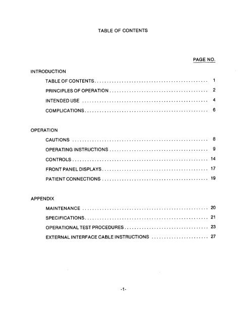
TABLE OF CONTENTS<br />
PAGE NO.<br />
TABLE OF CONTENTS. ............................................. 1<br />
PRlNCtPLES OF OPERATION. ....................................... 2<br />
INTENDEDUSE ................................................... 4<br />
COMPLICATIONS .................................................. 6<br />
CAUTIONS ....................................................... 8<br />
OPERATING INSTRUCTIONS ........................................ 9<br />
CONTROLS ....................................................... 14<br />
FRONT PANEL DISPLAYS. .......................................... 17<br />
PATIENT CONNECTIONS ........................................... 19<br />
MAINTENANCE ................................................... 20<br />
SPECIFICATIONS .................................................. 21<br />
OPERATIONAL TEST PROCEDURES. ................................. 23<br />
EXTERNAL INTERFACE CABLE INSTRUCTIONS ....................... 27
variable from 30 to 180 PPM.<br />
-2-<br />
<strong>NTP</strong>TM allows clear<br />
viewing and interpretation of the electrocardiogram on the<br />
screen, without the offset or distortion produced by the large<br />
electrical stimulus.<br />
<strong>NTP</strong>TM pacing electrodes placed on the<br />
back and the precordium. The characteristics of the output<br />
pulse, together with the design and placement of the electrodes,<br />
eliminate cutaneous nerve stimulation, lower cardiac stimulation<br />
thresholds, and reduce discomfort due to skeletal muscle<br />
contraction.<br />
The unique<br />
zoll<br />
PACE-VIEWTM feature of the <strong>Zoll</strong><br />
mA and the rate is continuously<br />
The pacing output pulse is delivered to the heart by two<br />
specially designed<br />
(<strong>NTP</strong>TM) is a self<br />
contained noninvasive cardiac pacemaker consisting of a demand<br />
pulse generator, a two trace non fade ECG monitor scope, and a<br />
strip chart recorder. The output current of the pacemaker is<br />
continuously variable up to 140<br />
PRINCIPLES OF OPERATION<br />
Noninvasive electric pacing is an established and proven<br />
technique. This device is safe and is easily and rapidly applied<br />
in both emergency and nonemergency situations when temporary<br />
cardiac stimulation is indicated.<br />
The <strong>Zoll</strong> Noninvasive Temporary <strong>Pacemaker</strong>
The entire system is lightweight, compact, and can be transported<br />
with a patient. Built-in batteries are kept at full charge when<br />
the unit is connected to line power. Electrode contact<br />
indicators alert the user to any problems due to poor contact or<br />
faulty connections. The monitor counts the heart rate and is<br />
equipped with adjustable high and low alarm limits.<br />
Proper operation of the instrument, together with correct<br />
electrode placement, is critical to obtaining the best results.<br />
The operator should be thoroughly familiar with the operating<br />
instructions found in the OPERATION<br />
<strong>Zoll</strong><br />
instrument.<br />
<strong>NTP</strong>TM pacing electrodes should<br />
-3-<br />
section of this manual. Only<br />
be connected to this
INTENDED USE<br />
For cardiac pacing for any purpose in conscious or unconscious<br />
patients for up to a few hours duration as an alternative to<br />
endocardial stimulation. The purposes of pacing include: 1)<br />
resuscitation from standstill or bradycardia of any etiology, 2)<br />
as a standby when standstill or bradycardia might be expected, 3)<br />
suppression of tachycardia.<br />
1. External pacing has been used for resuscitation from<br />
standstill or temporary acceleration of bradycardia in<br />
Stokes-Adams disease, Sick-sinus syndrome, reflex vagal<br />
standstill and drug-induced standstill (due to<br />
procainamide, quinidine, digitalis, B-blockers,<br />
verapamil, etc.) and unexpected circulatory arrest (due<br />
to anesthesia, surgery, angiography, and other<br />
therapeutic or diagnostic procedures). It is safer,<br />
more reliable, and more rapidly applied in an emergency<br />
than endocardial or other temporary electrodes.<br />
2. As a stand-by when arrest or symptomatic bradycardia<br />
might be expected, the external pacer is used especially<br />
in pacemaker procedures, in acute myocardial infarction,<br />
drug toxicity, and in anesthesia or surgery, especially<br />
when disturbances of rhythmicity or conduction are<br />
present. Prophylactic placement of endocardial<br />
-4-
electrodes, which carries risks of displacement,<br />
infection, hemorrhage, embolization, perforation,<br />
phlebitis, and mechanical or electrical stimulation of<br />
ventricular tachycardia and fibrillation can be avoided.<br />
3. An increase in heart rate from external pacing often<br />
suppresses ventricular ectopic activity and prevents<br />
tachycardia.<br />
-5
COMPLICATIONS<br />
ventricular fibrillation will not respond to pacing and requires<br />
immediate electrical defibrillation (if defibrillation is<br />
successful and standstill ensues, the Noninvasive Temporary<br />
<strong>Pacemaker</strong> should then be used). Ventricular or atria1<br />
tachycardias may be interrupted with pacing but in the emergency<br />
of circulatory collapse, other treatment (cardioversion) is<br />
faster and more certain, but requires anesthesia. Following<br />
prolonged cardiac arrest or in other disease states with<br />
myocardial depression, electromechanical dissociation may occur<br />
so that pacing may produce ECG responses without effective<br />
mechanical contractions, and other treatment is required.<br />
In the presence of generalized hypoxia, myocardial ischemia,<br />
cardiac drug toxicity, electrolyte imbalance, and other cardiac<br />
diseases, pacing may evoke repetitive responses, tachycardia, or<br />
fibrillation. A cardiac defibrillator should always be readily<br />
available and extra caution is needed to keep the stimulus<br />
amplitude just above threshold.<br />
Pacing by any method tends to inhibit intrinsic rhythmicity.<br />
Abrupt cessation of pacing, particularly at rapid rates, can<br />
cause ventricular standstill and should be avoided.<br />
-6-
The Noninvasive Temporary <strong>Pacemaker</strong> may cause discomfort of<br />
varying intensity, which may occasionally be severe and preclude<br />
its continued use in conscious patients. Similarly, unavoidable<br />
skeletal muscle contraction may be troublesome in very sick<br />
patients and may limit continuous use to a few hours. Erythema<br />
of the skin under the electrodes often occur but is<br />
inconsequential.<br />
There are reports of transient inhibition of spontaneous<br />
respiration in unconscious patients with previously available<br />
units when the anterior electrode was placed too low on the<br />
abdomen.<br />
This pacemaker is not appropriate for connection to internal<br />
pacemaker electrodes in contact with the myocardium. It should<br />
be used only with ZOLL <strong>NTP</strong> TM electrodes supplied by ZMI<br />
Corporation.<br />
-7-
1.<br />
2.<br />
3.<br />
4.<br />
5.<br />
6.<br />
7.<br />
8.<br />
apply BACK electrode as shown above.<br />
Apply FRONT electrode as shown above.<br />
Connect pacer output cable to<br />
Set the MODE switch to<br />
1:l or<br />
-9-<br />
mA.<br />
Set POWER switch to MONITOR ON.<br />
Adjust the ECG SIZE for a convenient waveform display<br />
and verify proper QRS detection. Note: Red QRS light<br />
on front panel flashes when proper detection of QRS is<br />
taking place.<br />
OPERATING INSTRUCTIONS<br />
Connect patient to 3 monitoring electrodes and input<br />
cable of ZOLL<br />
<strong>NTP</strong>TM.<br />
Set the OUTPUT control to 0<br />
<strong>NTP</strong>TM electrodes.<br />
4:l as desired.
9. Set the ESCAPE RATE to a value somewhat higher<br />
-lO-<br />
(lo-20<br />
PPM) than the patient's intrinsic rate. If no intrinsic<br />
QRS exists, use 60 PPM.<br />
10. Set the POWER switch to PACER ON.<br />
11. Observe the pacing artifact on the ECG trace and verify<br />
that it is well positioned in diastole.<br />
12. Increase the OUTPUT until evidence of capture is visible<br />
(refer to DETERMINING OPTIMUM THRESHOLD).
(0)<br />
(+)<br />
- It is important to recognize when<br />
stimulation has produced a ventricular response.<br />
Ventricular response is normally characterized by<br />
suppression of the intrinsic QRS and production of an<br />
ectopic QRST complex. The following tracings are<br />
typical.<br />
DETERMINING CAPTURE AND OPTIMUM THRESHOLD<br />
1. DETERMINING CAPTURE<br />
- INEFFECTIVE STIMULUS WITH NO - CAPTURE<br />
- EFFECTIVE STIMULUS WITH CAPTURE<br />
Note: Shape and size of the stimulated waveforms can vary<br />
depending on lead chosen. <strong>Clinical</strong> experience has shown Lead<br />
I produces the least distortion by the pacer stimulus,<br />
however, variation from patient to patient can be expected.<br />
-11-
2.<br />
3.<br />
DETERMINING OPTIMUM THRESHOLD<br />
55<br />
mA. The electrode placement that offers the most<br />
direct current pathway to the heart while avoiding large<br />
chest muscles will usually produce the lowest<br />
threshold. Low stimulation currents produce less<br />
skeletal muscle contraction and are better tolerated.<br />
Placement of the electrodes will affect the current<br />
required to obtain ventricular capture. The front<br />
electrode protective cap is designed in two parts. In<br />
tests of optimum electrode location, the center cap can<br />
be removed to expose only the gelled area of the<br />
electrode. Once the best location has been selected,<br />
the area should be cleansed of salt or other conductive<br />
materials, and the electrode may then be secured with<br />
the adhesive backing.<br />
4:1 TEST MODE<br />
- The<br />
is more comfortable, and it can be easier to interpret<br />
the stimulated response. The<br />
(1:l) when released.<br />
4:l test mode can be used optionally<br />
to test for threshold. In this mode a stimulus is<br />
delivered to the patient approximately every fourth<br />
intrinsic beat. (The stimulus is demand synchronized to<br />
the patient's intrinsic beat). On certain patients<br />
-12-<br />
- The ideal output current<br />
is the lowest value that will maintain capture. This is<br />
usually about 10% above threshold. Typical threshold<br />
currents have usually been between 40<br />
- 60<br />
4:l switch is<br />
mA, averaging<br />
spring-loaded. It will return to normal operating mode<br />
4:l
TO LOAD THE CHART PAPER:<br />
RECORDER<br />
1. Turn the POWER switch to MONITOR ON. Open paper carrier<br />
by pulling down the black handle at the top of the<br />
recorder. Take care not to touch the stylus at the top<br />
of the recorder assembly.<br />
-13-<br />
It is FRAGILE and HOT.<br />
2. Remove the empty paper core of the previous roll by<br />
pulling the clear plastic tab.<br />
3. Unroll about 5-6 inches of paper with the printed side<br />
up and insert the roll, making sure that the roll<br />
holders snap into the open ends of the paper core.<br />
Close the recorder door.<br />
4. Feed the edge of the paper between the drive rollers and<br />
push either of the RECORD buttons to advance the paper<br />
until the slack is taken up and the paper is aligned<br />
properly.
0 POWER<br />
0 RATE<br />
instrument.<br />
0 OUTPUT<br />
(mA).<br />
- The 3 position POWER switch activates the<br />
OFF<br />
operate.<br />
PACER ON<br />
the ECG trace.<br />
- All power in the unit is off. (Batteries<br />
will charge as long as unit is plugged in).<br />
MONITOR ON<br />
- Adjusts the pacer output from O-140 milliamps<br />
Output current is displayed in red digits below<br />
- The RATE control sets the rate at which the pacer<br />
will run unless suppressed by intrinsic QRS activity.<br />
RATE in pulses per minute (PPM) is displayed in red<br />
digits below the ECG trace. To adjust, push in and<br />
rotate the rate control knob. Due to the nature of the<br />
demand circuitry, there will be a difference between the<br />
rate selected for pacing and the actual pacing rate once<br />
capture is obtained.<br />
CONTROLS<br />
- Switch is down. Monitor and recorder<br />
- Switch is up. Activates pacer. The<br />
OUTPUT and RATE digital displays are illuminated on<br />
the front panel when pacer is on.<br />
-14-
0 MODE<br />
0 ECG SIZE<br />
cm/mV ) adjust the size of the display on the screen and<br />
the recorder.<br />
0 LEAD SELECTOR<br />
0 QRS BEEPER VOLUME<br />
beeper.<br />
- Rotate to select Lead I, Lead II, or<br />
Lead III. Note: <strong>Clinical</strong> experience has shown Lead I<br />
produces the least distortion by the pacer stimulus,<br />
however, variation from patient to patient can be<br />
expected.<br />
- The MODE switch controls the timing of the pacing<br />
pulse. The switch is spring-loaded and must be held in<br />
the<br />
4:l (test) mode.<br />
1:l (NORMAL)<br />
4:l (TEST)<br />
- The pacing stimuli are delivered to<br />
the patient at an interval equal to approximately<br />
every fourth beat synchronized with intrinsic<br />
activity.<br />
- The pacing stimuli are delivered to<br />
the patient at the rate selected by the RATE<br />
control.<br />
- Three calibrated positions<br />
- Adjusts the audio level of the QRS<br />
-15-<br />
(<br />
.5, 1, and 2
ALARM<br />
and<br />
0 FREEZE<br />
0 RECORD<br />
TEST<br />
,& symbols on the display screen are lit. The<br />
operator should maintain visual contact with the patient<br />
whenever the alarms are disabled.<br />
LOW ALARM LIMIT<br />
0 HIGH ALARM LIMIT<br />
- The ALARM pushbutton disables the heart rate<br />
alarms. When the alarms are disabled, the<br />
rate alarm limit.<br />
rate alarm limit.<br />
RECORD 2<br />
1mV<br />
- Push to freeze the lower ECG trace. Push a<br />
second time to release the trace.<br />
- The delayed ECG from either the upper or lower<br />
trace can be recorded. Push and hold in to operate.<br />
RECORD 1<br />
per minute (PPM).<br />
- records upper trace.<br />
- records lower trace.<br />
- Generates a rectangular test waveform<br />
internally for testing the display and rate counting<br />
circuitry. Test signal is<br />
- The slide control sets the low heart<br />
- The slide control sets the high heart<br />
-16-<br />
ALARM<br />
1mV amplitude and 120 pulses
0 POWER<br />
0 CHG<br />
<br />
w<br />
wand<br />
0 BATT<br />
0 HEART RATE<br />
0 OUTPUT<br />
- Illuminated when the instrument is plugged into<br />
1lOV power and batteries are being charged.<br />
- The low battery indicator will light up when<br />
batteries are near exhaustion. Battery operating time<br />
will depend on parameters of stimulation such as rate<br />
and output, as well as the amount of recorder operation.<br />
-17-<br />
mA) is displayed in<br />
red beneath the lower trace when the POWER switch is set<br />
to PACER ON.<br />
- The HEART RATE is digitally displayed<br />
beneath the ECG trace. The display range is 20-300<br />
beats per minute.<br />
J& symbols will be illuminated. THE OPERATOR<br />
SHOULD MAINTAIN VISUAL CONTACT WTIH THE PATIENT WHEN THE<br />
ALARMS ARE DISABLED.<br />
FRONT PANEL DISPLAYS<br />
- (GREEN LED) indicates power on.<br />
- When the heart rate alarms are disabled, the<br />
- The pacer's output (O-140
0 RATE<br />
0 QRS<br />
<br />
0<br />
- The QRS trigger indicator will flash when<br />
triggered by either an intrinsic beat or a stimulated<br />
QRS.<br />
- The pacing rate (30-180PPM) is displayed in red<br />
beneath the lower trace when the POWER switch is set to<br />
PACER ON.<br />
w- The ECG lead fault detector indicates a high<br />
impedance or open circuit condition in any of the 3 ECG<br />
electrodes or lead wires.<br />
Pyf- Flashes during pacing if a poor contact or open<br />
circuit exists between the<br />
-18-<br />
<strong>NTP</strong>TM pacing electrodes.
0 ECG INPUT<br />
0 PACER OUTPUT<br />
- Accepts model <strong>NTP</strong>-3002 output cable. The<br />
output stimulus of this device is intended for use with<br />
<strong>Zoll</strong><br />
- Accepts model <strong>NTP</strong>-3001 three lead patient<br />
cable. Connects to patient with standard disposable ECG<br />
monitoring electrodes.<br />
PATIENT CONNECTIONS<br />
<strong>NTP</strong>TM external pacing electrodes only.<br />
DO NOT CONNECT ANY OTHER DEVICE TO THE PACER OUTPUT.<br />
-19-
PACER OUTPUT<br />
Pulse Type:<br />
Synchronization:<br />
Pulse Duration:<br />
Pulse Amplitude:<br />
Pacing Rate:<br />
Output Protection:<br />
Isolation:<br />
ECG INPUT<br />
Patient Connection:<br />
Isolation:<br />
Input Protection:<br />
Overload Protection:<br />
CONTROLS<br />
Frequency Response:<br />
Rate:<br />
output:<br />
ECG Size:<br />
Calibration:<br />
Test Mode:<br />
QRS Beeper Volume:<br />
Alarm Limits:<br />
Power:<br />
Recorder Activation:<br />
Freeze Control:<br />
SPECIFICATIONS<br />
MODEL <strong>NTP</strong>-1000<br />
Rectilinear, constant current<br />
Full demand pacing<br />
40 milliseconds<br />
Variable O-140<br />
mA<br />
Variable, 30-180 PPM<br />
Fully defibrillator protected<br />
Meets AAMI, VA, CSA specifications<br />
Via 3 lead ECG Cable (supplied with<br />
instrument)<br />
Meets AAMI, VA, CSA specifications<br />
Fully defibrillator protected<br />
Patented PACE-VIEWTM feature prevents<br />
distortion of ECG by pacer stimulus<br />
DC-40hz (-3db)<br />
Variable, 30-180 PPM<br />
variable, O-140 mA<br />
3 Position, .5, 1, 2 cm/mV<br />
Push button 1 mv signal checks display<br />
circuits and rate meter<br />
1:l (normal) and 4:l (test) modes<br />
Adjustable<br />
High and Low alarm slide controls, alarm<br />
range O-240 BPM<br />
3 position toggle switch, power off,<br />
monitor only, monitor and pacer on<br />
Push button, upper or lower trace can be<br />
recorded<br />
Push button, freezes lower trace<br />
-21-
GENERAL<br />
Type: Specially designed anterior/posterior<br />
pregelled, zoll <strong>NTP</strong>TM disposable<br />
electrodes. Packaged in pairs.<br />
RECORDER<br />
ECG Waveform:<br />
Display Screen:<br />
Viewing Time:<br />
Heart Rate:<br />
Output Current:<br />
Pacer Rate:<br />
ECG Lead Fault:<br />
Pacer Electrode<br />
ELECTRODES<br />
Type: Single channel hot stylus<br />
Paper: 40 mm thermal<br />
Speed: 25 mm/second<br />
Delay: 4 or 8 seconds<br />
Type:<br />
Running Time:<br />
Battery Status:<br />
Recharge Time:<br />
Size:<br />
Weight:<br />
Power Requirements:<br />
Power Consumption:<br />
Two trace cascade format, lower trace<br />
can be frozen<br />
5.5" non-fade, two color<br />
4 seconds per trace<br />
Digital display O-240 BPM<br />
Digital display O-140<br />
mA<br />
Digital display 30-180 PPM<br />
LED indicator, front panel<br />
Fault: LED indicator, front panel<br />
Nickel cadmium, rechargeable,<br />
self-contained<br />
Approximately 1 l/2 hours<br />
LED indicator front panel<br />
16 hours for fully discharged pack<br />
6"H x 12"W x 15"D<br />
18 lbs. fully equipped<br />
loo-117 volts 60 HZ<br />
45 watts<br />
-22