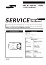
microwave oven
microwave oven
microwave oven

Create successful ePaper yourself
Turn your PDF publications into a flip-book with our unique Google optimized e-Paper software.
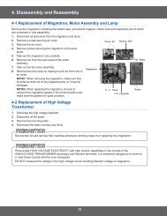
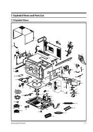
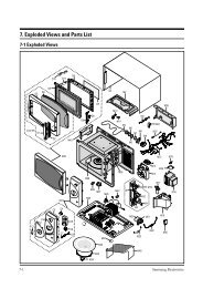
Alignment and Adjustments<br />
5-4 High Voltage Capacitor<br />
1. Check continuity of the capacitor with the meter set at the highest resistance scale.<br />
2. Once the capacitor is charged, a normal capacitor shows continuity for a short time, and then indicates 9MΩ.<br />
3. A shorted capacitor will show continuous continuity.<br />
4. An open capacitor will show constant 9MΩ.<br />
5. Resistance between each terminal and chassis should read infinite.<br />
5-5 High Voltage Diode<br />
1. Isolate the diode from the circuit by disconnecting its leads.<br />
2. With the ohm-meter set at the highest resistance scale, measure across the diode terminals. Reverse the<br />
meter leads and read the resistance. A meter with 6V, 9V or higher voltage batteries should be used to<br />
check the front-to back resistance of the diode (otherwise an infinite resistance may be read in both<br />
directions). The resistance of a normal diode will be infinite in one direction and several hundred KΩ in<br />
the other direction.<br />
5-6 Main Relay and Power Control Relay<br />
1. The relays are located on the PCB Ass'y. Isolate them from the main circuit by disconnecting the leads.<br />
2. Operate the <strong>microwave</strong> <strong>oven</strong> with a water load in the <strong>oven</strong>. Set the power level set to high.<br />
3. Check continuity between terminals of the relays after the start pad is pressed.<br />
5-7 Adjustment of Primary Switch, Door Sensing Switch and Monitor Switch<br />
Precaution<br />
For continued protection against radiation hazard, replace parts in accordance with the wiring diagram and be sure to use the<br />
correct part number for the following switches: Primary and secondary interlock switches, and the interlock monitor switch<br />
(replace all together). Then follow the adjustment procedures below. After repair and adjustment, be sure to check the continuity<br />
of all interlock switches and the interlock monitor switch.<br />
1. When mounting Primary switch and Interlock<br />
Monitor switch to Latch Body, consult the figure.<br />
2. No specific adjustment during installation of<br />
Primary switch and Monitor switch to the latch<br />
body is necessary.<br />
3. When mounting the Latch Body to the <strong>oven</strong><br />
assembly, adjust the Latch Body by moving it so<br />
that the <strong>oven</strong> door will not have any play in it.<br />
Check for play in the door by pulling the door<br />
assembly. Make sure that the latch keys move<br />
smoothly after adjustment is completed.<br />
Completely tighten the screws holding the Latch<br />
Body to the <strong>oven</strong> assembly.<br />
4. Reconnect to Monitor switch and check the<br />
continuity of the monitor circuit and all latch<br />
switches again by following the components test<br />
procedures.<br />
5. Confirm that the gap between the switch<br />
housing and the switch actuator is no more than<br />
0.5mm when door is closed.<br />
5-2<br />
Body Latch<br />
Primary Interlock Switch<br />
Interlock<br />
Monitor<br />
Switch<br />
Lever Door(B)<br />
Door Sensing<br />
Switch<br />
Door Open Door Closed<br />
Primary switch ∞ 0<br />
Monitor switch (COM-NC) 0 ∞<br />
Monitor switch (COM-NO) ∞ 0<br />
Door Sensing S/W ∞ 0<br />
Samsung Electronics