SAMSUNG CE959GT.pdf
SAMSUNG CE959GT.pdf
SAMSUNG CE959GT.pdf

You also want an ePaper? Increase the reach of your titles
YUMPU automatically turns print PDFs into web optimized ePapers that Google loves.
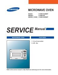
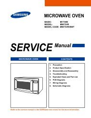
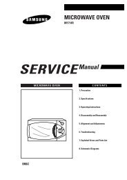
MICROWAVE OVEN<br />
<strong>CE959GT</strong> (DARK GRAY)<br />
SERVICE Manual<br />
Supplement<br />
THIS SUPPLEMENT CONTAINS EXPLODED VIEW AND PARTS LIST FOR MODEL <strong>CE959GT</strong>(DARK<br />
GRAY). FOR MORE SERVICING INFORMATION, PLEASE CONSULT THE PREVIOUS SERVICE<br />
MANUAL FOR CE959G WHICH WAS DISTRIBUTED IN JULY 1998.<br />
AMFO<br />
MICROWAVE OVEN CONTENTS<br />
1. 2. 3.<br />
1. 2. 3.<br />
1 min +<br />
Auto<br />
Auto<br />
Auto<br />
1. 2. 3.<br />
1. Precaution<br />
2. Control Panel<br />
3. Exploded View & Parts List<br />
4. P.C.B Diagram<br />
5. Schematic Diagrams<br />
Specifications<br />
TIMER 99 MINUTES 90 SECONDS<br />
POWER SOURCE 230V/50HZ, AC<br />
POWER CONSUMPTION MICROWAVE : 1,500W<br />
GRILL : 1,300W<br />
OUTPUT POWER FROM90 TO 900W<br />
OPERATING FREQUENCY 2,450MHz<br />
(10 LEVEL POWER)<br />
MAGNETRON OM75PH(31)<br />
(IEC-705 TEST PROCEDURE)<br />
COOLING METHOD COOLING FAN MOTOR<br />
OUTSIDE DIMENSIONS 517(W) x 297(H) x 410(D)<br />
NET WEIGHT 20 Kg<br />
SHIPPING WEIGHT 22 Kg
PRECAUTIONS TO BE OBSERVED BEFORE AND<br />
DURING SERVICING TO AVOID POSSIBLE<br />
EXPOSURE TO EXCESSIVE MICROWAVE ENERGY<br />
(a) Do not operate or allow the oven to be<br />
operated with the door open.<br />
(b) Make the following safety checks on<br />
all ovens to be serviced before activating<br />
the magnetron or other microwave<br />
source, and make repairs as necessary:<br />
(1) Interlock operation,<br />
(2) proper door closing,<br />
(3) seal and sealing surfaces (arcing,<br />
wear, and other damage),<br />
(4) damage to or loosening of hinges<br />
and latches,<br />
(5) evidence of dropping or abuse.<br />
(c) Before turning on microwave power<br />
for any service test or inspection within<br />
the microwave generating<br />
compartments, check the magnetron,<br />
wave guide or transmission line, and<br />
cavity for proper alignment, integrity,<br />
and connections.<br />
(d) Any defective or misadjusted<br />
components in the interlock, monitor,<br />
door seal, and microwave generation<br />
and transmission systems shall be<br />
repaired, replaced, or adjusted by<br />
procedures described in this manual<br />
before the oven is released to the owner.<br />
(e) A Microwave leakage check to verify<br />
compliance with the Federal<br />
performance standard should be<br />
performed on each oven prior to release<br />
to the owner.<br />
Samsung Electronics
1. Precaution<br />
Follow these special safety precautions. Although the microwave oven is completely safe during ordinary<br />
use, repair work can be extremely hazardous due to possible exposure to microwave radiation, as well as<br />
potentially lethal high voltages and currents.<br />
1-1 Safety precautions ( )<br />
1. All repairs should be done in accordance<br />
with the procedures described in this<br />
manual. This product complies with<br />
Federal Performance Standard 21 CFR<br />
Subchapter J (DHHS).<br />
2. Microwave emission check should be<br />
performed to prior to servicing if the oven is<br />
operative.<br />
3. If the oven operates with the door open :<br />
Instruct the user not to operate the oven and<br />
contact the manufacturer and the center for<br />
devices and radiological health immediatly.<br />
4. Notify the Central Service Center if the<br />
microwave leakage exceeds 5 mW/cm 2<br />
5. Check all grounds.<br />
6. Do not power the MWO from a "2-prong"<br />
AC cord. Be sure that all of the built-in<br />
protective devices are replaced. Restore any<br />
missing protective shields.<br />
7. When reinstalling the chassis and its<br />
assemblies, be sure to restore all protective<br />
devices, including: nonmetallic control<br />
knobs and compartment covers.<br />
8. Make sure that there are no cabinet openings<br />
through which people--particularly<br />
children--might insert objects and contact<br />
dangerous voltages. Examples: Lamp hole,<br />
ventilation slots.<br />
9. Inform the manufacturer of any oven found<br />
to have emmission in excess of 5 mW/cm 2,<br />
Make repairs to bring the unit into<br />
compliance at no cost to owner and try to<br />
determine cause.<br />
Instruct owner not to use oven until it has<br />
been brought into compliance.<br />
CENTRAL SERVICE CENTER<br />
10. Service technicians should remove their<br />
watches while repairing an MWO.<br />
11. To avoid any possible radiation hazard,<br />
replace parts in accordance with the wiring<br />
diagram. Also, use only the exact<br />
replacements for the following parts:<br />
Primary and secondary interlock switches,<br />
interlock monitor switch.<br />
12. If the fuse is blown by the Interlock Monitor<br />
Switch: Replace all of the following at the<br />
same time: Primary and secondary switches,<br />
as well as the Interlock Monitor Switch. The<br />
correct adjustment of these switches is<br />
described elsewhere in this manual. Make<br />
sure that the fuse has the correct rating for<br />
the particular model being repaired.<br />
13. Design Alteration Warning:<br />
Use exact replacement parts only, i.e., only<br />
those that are specified in the drawings<br />
and parts lists of this manual. This is<br />
especially important for the Interlock<br />
switches, described above. Never alter or<br />
add to the mechanical or electrical design<br />
of the MWO. Any design changes or<br />
additions will void the manufacturer's<br />
warranty.10.Always unplug the unit's AC<br />
power cord from the AC power source<br />
before attempting to remove or reinstall<br />
any component or assembly.<br />
14. Never defeat any of the B+ voltage<br />
interlocks. Do not apply AC power to the<br />
unit (or any of its assemblies) unless all<br />
solid-state heat sinks are correctly installed.<br />
15. Some semiconductor ("solid state") devices<br />
are easily damaged by static electricity. Such<br />
components are called Electrostatically<br />
Sensitive Devices (ESDs). Examples include<br />
integrated circuits and field-effect<br />
transistors.<br />
Immediately before handling any<br />
semiconductor components or assemblies,<br />
drain the electrostatic charge from your<br />
body by touching a known earth ground.<br />
16. Always connect a test instrument's ground<br />
lead to the instrument chassis ground before<br />
connecting the positive lead; always remove<br />
the instrument's ground lead last.<br />
Samsung Electronics 1-1
Pretaution<br />
1-2 Special Servicing Precautions (Continued)<br />
17. When checking the continuity of the witches<br />
or transformer, always make sure that the<br />
power is OFF, and one of the lead wires is<br />
disconnected.<br />
18. Components that are critical for safety are<br />
indicated in the circuit diagram by<br />
shading, or .<br />
19. Use replacement components that have the<br />
same ratings, especially for flame resistance<br />
and dielectric strength specifications. A<br />
replacement part that does not have the<br />
same safety characteristics as the original<br />
might create shock, fire or other hazards.<br />
1-3 Special High Voltage Precautions<br />
1. High Voltage Warning<br />
Do not attempt to measure any of the high<br />
voltages--this includes the filament voltage<br />
of the magnetron. High voltage is present<br />
during any cook cycle.<br />
Before touching any components or wiring,<br />
always unplug the oven and discharge the<br />
high voltage capacitor (See Figure 1-1)<br />
2. The high-voltage capacitor remains charged<br />
about 30 seconds after disconnection. Short<br />
the negative terminal of the high-voltage<br />
capacitor to the oven chassis. (Use a<br />
screwdriver.)<br />
3. High voltage is maintained within specified<br />
limits by close-tolerance, safety-related<br />
components and adjustments. If the high<br />
voltage exceeds the specified limits, check<br />
each of the special components.<br />
1-2<br />
Fig. 1-1. Discharging the High Voltage Capacitor<br />
Samsung Electronics
2. Control Panel<br />
Combi Button<br />
Grill Button<br />
Samsung Electronics<br />
1. 2. 3.<br />
1. 2. 3.<br />
1 min +<br />
1. 2. 3.<br />
Auto<br />
Auto<br />
Auto<br />
CE959G<br />
Auto Reheat Programs<br />
Auto Cook Programs<br />
Power Level Button<br />
Auto Defrost Programs<br />
More/Less Button<br />
Cancel Button<br />
Clock Setting Button<br />
Start Button<br />
2-1
2. Specifications<br />
2-1 Table of Specifications<br />
ITEM<br />
MODEL CE959G<br />
TIMER 99 MINUTES 90 SECONDS<br />
POWER SOURCE 230V/50HZ, AC<br />
POWER CONSUMPTION MICROWAVE : 1,500W<br />
GRILL : 1,300W<br />
OUTPUT POWER FROM90 TO 900W<br />
(10 LEVEL POWER)<br />
(IEC-705 TEST PROCEDURE)<br />
OPERATING FREQUENCY 2,450MHz<br />
MAGNETRON OM75PH(31)<br />
COOLING METHOD COOLING FAN MOTOR<br />
OUTSIDE DIMENSIONS 517(W) x 297(H) x 410(D)<br />
NET WEIGHT 20 Kg<br />
SHIPPING WEIGHT 22 Kg<br />
2-2 Comparison Chart<br />
FEATURE<br />
MODEL<br />
CE959G<br />
MORE/LESS O<br />
AUTO REHEAT O<br />
AUTO DEFROST O<br />
AUTO COOK O<br />
TIME COOK O<br />
POWER LEVEL (10) O<br />
CHILD LOCK O<br />
CLOCK O<br />
GRILL O<br />
COMBI O<br />
BEEPER ON/OFF O<br />
POWER LEVEL<br />
ON TIME OFF TIME<br />
% CE959G<br />
10% 90W 4 sec 26 sec<br />
20% 180W 7 sec 23 sec<br />
30% 270W 10 sec 20 sec<br />
40% 360W 13 sec 17 sec<br />
50% 450W 16 sec 14 sec<br />
60% 540W 19 sec 11 sec<br />
70% 630W 22 sec 8 sec<br />
80% 720W 25 sec 5 sec<br />
90% 810W 28 sec 2 sec<br />
100% 900W 30 sec 0 sec<br />
Samsung Electronics 2-1
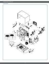
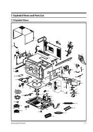
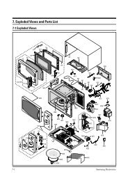
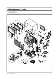
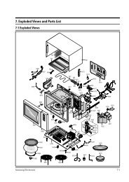
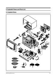
3. Exploded Views and Parts List<br />
3-1 Exploded Views<br />
D12<br />
C1<br />
D3<br />
D1<br />
D4<br />
C3<br />
C2<br />
D11<br />
D2<br />
C16<br />
D5<br />
C4<br />
C5<br />
D6<br />
D9<br />
D10<br />
M25<br />
C7<br />
M26<br />
C6<br />
C10<br />
C13 C9<br />
C8<br />
C11<br />
C12<br />
C15<br />
C14<br />
M34<br />
D8<br />
M35<br />
D7<br />
M36<br />
M32<br />
M1<br />
M39<br />
M41<br />
M22<br />
M20<br />
M3<br />
M33<br />
M2<br />
M42<br />
M21<br />
M19<br />
M12<br />
M37<br />
M28<br />
M11<br />
M27<br />
B1<br />
M41<br />
M4<br />
M45<br />
B2<br />
M13 M14<br />
M15<br />
M49<br />
M6<br />
M10<br />
B4<br />
M38<br />
M43<br />
M5<br />
M7<br />
3-1 Samsung Electronics<br />
M8<br />
B3<br />
B5<br />
M16<br />
M24<br />
M48<br />
M18<br />
M17<br />
M9<br />
M46<br />
M50<br />
M40<br />
M31<br />
M29<br />
M23<br />
M44<br />
M51<br />
M30<br />
M47
Exploded Views and Parts List<br />
4-2 Main Parts List<br />
Ref. No. Parts No. Description/Specification Q'ty Remarks<br />
M 1 DE70-30001C PANEL-OUTER;V/STEEL,T0.7,360,1128,STONE-GR 1<br />
M 2 DE63-90035G CUSHION-RUBBER;DFA20,T2,W190,L100,BLK 1<br />
M 3 DE61-50017A BRACKET-UPPER;SECC1,T0.6,340,216 1<br />
M 4 DE47-70031G HEATER-GRILL;D6.6,230V1280W,M9G45,SJH 1<br />
M 5 DE63-20017A GASKET-HEATER;BRASS,T1.5,OD30.5,ID22.5 1<br />
M 6 DE60-40009B WASHER-TEFLON;SLOT,ID22.2,OD28,T1.2,TEFLON 1<br />
M 7 DE61-50021A BRACKET-FLANGE;SECC1,T0.8,32,32 1<br />
M 8 DE61-50347A BRACKET-EARTH;BSS2-A,T1.0,W35,L43,MBGF45 1<br />
M 9 DE61-50027B BRACKET-HEATER;SECC,T1.0,W51,L55,CE945GF 1<br />
M 10 DE93-20020A ASSY BODY LATCH;RE-43B/90B 1<br />
M 11 DE73-90027A FERRITE-CORE;NI-ZN,T13.8,W21.0,L28.0,BNF-14 1<br />
M 12 DE26-10100A TRANS-H.V;SHV-945EG1,230V,2280V/3.15V,50 1<br />
M 13 2501-001030 C-OIL;1.1uF,2100V,BK,35x54x95,20mm 1<br />
M 14 DE61-50106A BRACKET-HVC;SECC,T0.8,W31,L125.8 1<br />
M 15 DE59-40001A DIODE-H.V;HVR-1X-32B-12 1<br />
M 16 DE91-70061A ASSY-H.V.FUSE;THV060T-0800-H,5KV/0.8A,WHT 1<br />
M 17 DE31-10156A MOTOR-FAN;SMF-945EA,230/50,2400,M97G45 1<br />
M 18 DE91-40095A ASSY NOISE FILTER;SN-E10D(N),250V,10A,2ND-WD-TYP 1<br />
M 19 DE61-40017A FOOT;PP(A353),BLK,MW5630T 2<br />
M 20 DE80-10001A BASE-PLATE;SGCC,T0.8,345,565, 1<br />
M 21 DE31-10154A MOTOR-DRIVE;M2HJ49ZR02,ST-16,21V,5/6 1<br />
M 22 DE71-60382A COVER-CEILING;MICASHEET,T0.5,70,133 1<br />
M 23 DE71-60016A COVER-AIR;PP,2,WHT,M945/M245 1<br />
M 24 4713-001031 LAMP-INCANDESCENT;230V,173mA,40W,ORG,-,-,25x69mm 1<br />
M 25 DE94-00024A ASSY DOOR;<strong>CE959GT</strong>-D,DARK-GRAY,AMFO 1<br />
M 26 DE94-00025A ASSY CONTROL-BOX;230V50HZ,<strong>CE959GT</strong>-D,DARK-GRAY,AMFO 1<br />
M 27 DE61-30006A SUPPORTER-HEATER;ALUMINA,5G,2ND-W/P 1<br />
M 28 DE61-70060A SPRING-PLATE;SK-5,T0.5 1<br />
M 29 DE61-50490A BRACKET-TCO;SECC1,T0.6,34,58 1<br />
M 30 DE03-30035A MAGNETRON;OM75PH((31)ESS 1<br />
M 31 DE47-20009A THERMOSTAT;PW2N-520PB,160/60,250V/7.5A,H, 1<br />
M 32 DE47-20161A THERMOSTAT;PW2N(120/110)187Z23.,250V/7.5A 1<br />
M 33 DE47-20008A THERMOSTAT;PW2N-52JC,100/60,250V/7.5A,H,1 1<br />
M 34 DE74-20015B TRAY-COOKING;GLASS,T6.0,PI318,1050G,MW5630T 1<br />
M 35 DE92-90189D ASSY-GUIDE ROLLER;D19,STD 1<br />
M 36 DE67-60075A COUPLER;PPS,7G,BRN,M97G45 1<br />
M 37 DE74-70003A RACK WIRE;MSWR3,3,290,125,SNC2,CE945G 1<br />
M 38 DE65-20014A CABLE CLAMP;DA-6N,NY-66 1<br />
M 39 DE72-60005A GUIDE-AIR;SECC1-P,T0.5,210,225 1<br />
M 40 DE92-90524A ASSY-COVER BACK;CE945G 1<br />
M 41 DE63-90065N CUSHION-GUIDE;PUT-FOAM,T10,W10,L200,BLK,MW55 2<br />
M 42 DE63-90065O CUSHION-GUIDE;PUT-FOAM,T35,W20,L135,BLK,MW55 1<br />
M 43 DE39-40409A WIRE HARNESS-E;230V50HZ,M9G45,CTW 1<br />
M 44 DE39-40568A WIRE HARNESS-A;230V50HZ,CE745G/CE945G 1<br />
M 45 DE39-20058C ASSY POWER CORD;KKP-4819D/B232,250V16A,L1700,G 1<br />
M 46 DE91-70101C ASSY-THERMOSTAT;MW5574W,160/60,187-HORIZ 1<br />
M 47 DE74-20107A TRAY BROILER;CE945GF(SSW),MW5574W 1<br />
Samsung Electronics<br />
3-2
3-3 Door Parts List<br />
3-4 Control Parts List<br />
3-5 Body Latch Parts List<br />
3-3<br />
Exploded Views and Parts List<br />
Ref. No. Parts No. Description/Specification Q'ty Remarks<br />
D 1 DE64-20112J HANDLE;ABS(HR0370),30G,-,-,-,D/GRAY,M959-D 1<br />
D 2 DE94-00013A ASSY DOOR-A;M959-D,D/GRAY 1<br />
D 3 DE64-40263P DOOR-A;ABS,-,M959-D 1<br />
D 4 DE64-40265D DOOR-SCREEN;ACRYL(IF850)ED17,M959 1<br />
D 5 DE92-50127H ASSY DOOR-E;COATING,BLACK,T0.8 1<br />
D 6 DE64-40012A DOOR-C;RESIN-PP(TB53),T2.0,CE945GF,BL 1<br />
D 7 DE01-00002A FILM-DOOR;PET,T0.15,275,175,NTR,CE945GF 1<br />
D 8 DE61-70126A SPRING-KEY;0.8,0,36,6,BLUING” 1<br />
D 9 DE64-40264C DOOR-KEY;POM(F20-02),5g,BLK,1,2ND,HANDL 1<br />
D 10 DE61-80003A HINGE-LOWER;SCP1,T2.3,26,77,ZPC3,WHT,CE945 1<br />
D 11 DE61-80002A HINGE-UPPER;SCP1,T2.3,26,77,ZPC3,WHT,CE945 1<br />
Ref. No. Parts No. Description/Specification Q'ty Remarks<br />
C 1 DE71-00002A COVER-PANEL;ABS(HR0370D),-,-,-,<strong>CE959GT</strong>-D,DARK-GRAY 1<br />
C 2 DE67-40145A WINDOW-DISPLAY;ACRYL,T2,W40,L77,SMOG,30G 1<br />
C 3 DE72-70211Q CONTROL-PANEL;ABS(HR0370D),WHT,-,-,<strong>CE959GT</strong>-D 1<br />
C 4 DE66-00001A BUTTON-SELECT(A);PC 1<br />
C 5 DE66-20197V BUTTON-SELECT(A-B);PC,-,-,M959-D,D/GRAY 1<br />
C 6 DE66-20198V BUTTON-SELECT(A-C);PC,-,-,M959-D,D/GRAY 1<br />
C 7 DE66-20179A BUTTON-SELECT;ABS(HR0370),NTR,30G,RE-445 1<br />
C 8 DE91-10537A ASSY PCB-MAIN;RC-959G-00,230V50Hz,VFD,CE959G 1<br />
C 9 DE66-20175L BUTTON-SELECT(B);ABS(HR0370),-,-,M959-D,D/GRAY 1<br />
C 10 DE66-20176L BUTTON-SELECT(C);ABS(HR0370),-,-,M959-D,D/GRAY 1<br />
C 11 DE66-20177M BUTTON-SELECT(D);ABS(HR0370),-,-,M959-D,D/GRAY 1<br />
C 12 DE66-20178M BUTTON-SELECT(E);ABS(HR0370),-,-,M959-D,D/GRAY 1<br />
C 13 DE64-10127F KNOB-COVER;ABS(HR0370D),-,<strong>CE959GT</strong>-D 1<br />
C 14 DE66-20182G BUTTON-START;ABS(HR0370D),-,-,DE959GT-D,DARK-GRAY 1<br />
C 15 DE71-60378A COVER-LAMP;POM,T2,W19.4,L27,3G,NTR,RE-446 1<br />
C 16 DE94-00021A ASSY CONTROL-PANEL;-,<strong>CE959GT</strong>-D,DARK-GRAY,AMFO 1<br />
Ref. No. Parts No. Description/Specification Q'ty Remarks<br />
B 1 DE66-40001A LATCH-BODY;POM(F20-02) 40GR NTR 1<br />
B 2 3405-000178 SWITCH-MICRO;VP-533A-OF-PS(T85) 250V,15A 2<br />
B 3 3405-000175 SWITCH-MICRO;VP-531A-OF(T85) 250V,15A,20 1<br />
B 4 DE66-90001A LEVER-SWITCH;P.O.M(F20-02) 2 6 NTR 2ND-W 1<br />
: Option Parts : Warning :Electrostatically Sensitive Devices<br />
Samsung Electronics
Exploded Views and Parts List<br />
3-6 Standard Parts List<br />
Parts No. Description / Specification Q'ty Remarks<br />
DE60-10012A SCREW-TAP TITE;TH,+,3,M4,L10,SWR10,ZPC2,TOOTH 1 N-F-EA<br />
DE60-10012A SCREW-TAP TITE;TH,+,3,M4,L10,SWR10,ZPC2,TOOTH 1 P-C-EA<br />
DE60-10012A SCREW-TAP TITE;TH,+,3,M4,L10,SWR10,ZPC2,TOOTH 1 S-M-EA<br />
DE60-10013A SCREW-ASSY TAP;TH,2S,4,L12,MSWR3,ZPC3,FIBER 1 MO/FAN<br />
DE60-10018A SCREW-ASSY MACHINE;PH,M4X0.7P,8,MSWR10,SN1,WS 2 B/EATH<br />
DE60-10024A SCREW-PH;PH,+,M4,L8,MSWR10,ZPC3 2 B/HEAT<br />
DE60-10045A SCREW-TAP PH;PH,M3,L6,FEFZY 2 MG-TCO<br />
DE60-10069A SCREW-TAP TH;TH,M4,L10,FRFZY 3 B/UPPE<br />
DE60-10069A SCREW-TAP TH;TH,M4,L10,FRFZY 1 CV/AIR<br />
DE60-10072A SCREW-TAP TH;TH,M4,L16,FEFZY,2-SLOT 1 CB-CMP<br />
DE60-10080A SCREW-WASHER;M5,L12,2S 4 MGT<br />
DE60-10080A SCREW-WASHER;M5,L12,2S 4 TNS-HV<br />
DE60-10082H SCREW-A;2S-4X12,TOOTHED 2 B-PLTE<br />
DE60-10082H SCREW-A;2S-4X12,TOOTHED 2 CN-BOX<br />
DE60-10082H SCREW-A;2S-4X12,TOOTHED 2 LATCH<br />
DE60-10082H SCREW-A;2S-4X12,TOOTHED 5 PN-OUT<br />
DE60-10098A SCREW-ASSY TAP TITE;PH,TC,M4X8,SWRCH18A,ZPC2,GLD,W 1 CV-TCO<br />
DE60-10098A SCREW-ASSY TAP TITE;PH,TC,M4X8,SWRCH18A,ZPC2,GLD,W 2 M/DRIV<br />
DE60-10122A SCREW-TAP TH;TAP,TH,2-4X8,FE,FN 2 C-CEIL<br />
DE60-20063A BOLT-FLANGE;M4,10,ZPC3,YEL,MSWR 2 HI-LOW<br />
DE60-20063A BOLT-FLANGE;M4,10,ZPC3,YEL,MSWR 2 HI-UPP<br />
DE60-10045A SCREW-TAP PH;PH,M3,L6,FEFZY 1 -<br />
DE60-10066A SCREW-TAP TH;TH,M4,L8,FEFZY,2-SLOT 2 H/DOOR<br />
DE60-10012A SCREW-TAP TITE;TH,+,3,M4,L10,SWR10,ZPC2,TOOTH 1 -<br />
DE60-10098A SCREW-ASSY TAP TITE;PH,TC,M4X8,SWRCH18A,ZPC2,GLD,W 1 -<br />
DE60-10088A SCREW-TAP PH;PH,M3,L8,FEFZY,PLAIN 12 CON/PANEL<br />
DE60-10045A SCREW-TAP PH;PH,M3,L6,FEFZY 1 GR-TCO<br />
Samsung Electronics<br />
3-4
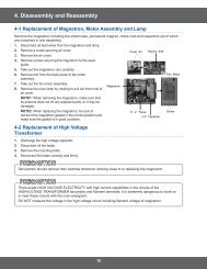
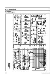
4. P.C.B Diagrams<br />
4-1 P.C.B Diagrams<br />
4-1 Samsung Electronics
4-2 P.C.B Parts List<br />
Parts No. Description / Specification Q'ty Remarks<br />
Samsung Electronics<br />
P.C.B Diagrams<br />
3501-001050 RELAY-MINIATURE;24VDC,200mW,5A,1FormA,10mS,5mS 2 RY02,RY03<br />
3501-001062 RELAY-POWER;24VDC,523.2mW,16A,1FormA,15mS 1 RY01<br />
3501-001068 RELAY-POWER;24Vdc,523mW,16A,1FormA,15mS,10 1 RY04<br />
DE07-10081A V.F.DISPLAY;SVM-4SM03,GRN/RSHORG,4,51,81.7 1 VFD1<br />
DE09-30725A IC-MCU;HD404316-D48S,CE959G 1 IC01<br />
DE26-20141A TRANS-L.V;SLV-945E,230V,50HZ,AC17/2.9V 1 LVT1<br />
DE30-20016A BUZZER;CBE2220BA,STICK 1 BUZ1<br />
DE39-40723A WIRE HARNESS;DC35V,C-959G,80mm,12PIN 1 CN05<br />
DE61-90320A HOLDER-DIGITRON;PP,-,W37,L83.3,-,CE959G 1 -<br />
DE91-20635A ASSY PCB AUTO-MAIN;230V50Hz,VFD,CE959G 1 -<br />
0401-001002 DIODE-SWITCHING;1N4148M,100V,200mA,500mW,3nS,D 11 D04~D14<br />
0402-001103 DIODE-RECTIFIER;1T4,400V,1A,TS-1,TP 3 D01~D03<br />
0403-000717 DIODE-ZENER;MTZJ5.1B,5.1V,4.94-5.2V,500mW 3 ZD01~ZD03<br />
0501-000388 TR-SMALL SIGNAL;KSC815,NPN,400mW,TO-92,BK,120 1 TR01<br />
0504-001014 TR-DIGITAL;KSR1005,NPN,300mW,4.7K-10K,TO- 5 TR02~TR06<br />
0504-001015 TR-DIGITAL;KSR2005,PNP,300mW,4.7K-10K,TO- 1 TR08<br />
2001-000037 R-CARBON(S);330ohm,5%,1/2W,AA,TP,2.4x6.4mm 2 R01,R02<br />
2001-000290 R-CARBON;10Kohm,5%,1/8W,AA,TP,1.8x3.2mm 4 R13,R14,R18,R19<br />
2001-000429 R-CARBON;1Kohm,5%,1/8W,AA,TP,1.8x3.2mm 7 R05,R06,R09~R11,R16,R17<br />
2001-000435 R-CARBON;1Mohm,5%,1/8W,AA,TP,1.8x3.2mm 1 R07<br />
2001-000613 R-CARBON;3.9Kohm,5%,1/8W,AA,TP,1.8x3.2m 2 R08R15<br />
2001-000780 R-CARBON;470ohm,5%,1/8W,AA,TP,1.8x3.2mm 3 R03,R04,R12<br />
2001-000786 R-CARBON;47Kohm,5%,1/8W,AA,TP,1.8x3.2mm 4 R22~R25<br />
2202-000127 C-CERAMIC,MLC-AXIAL;10nF,+80-20%,25V,Y5V,TP,-,7.5 2 C11,C12<br />
2202-000780 C-CERAMIC,MLC-AXIAL;100nF,+80-20%,50V,Y5V,TP,3.5x1 4 C07~C10<br />
2202-000796 C-CERAMIC,MLC-AXIAL;1nF,10%,50V,Y5P,TP,3.5x19 3 C15~C17<br />
2401-000247 C-AL;100uF,20%,10V,GP,-,6.3x11mm,5m 1 C03<br />
2401-000914 C-AL;22uF,20%,16V,GP,TP,5x11,5 2 C04,C06<br />
2401-001268 C-AL;4.7uF,20%,50V,GP,TP,5x11,5 1 C05<br />
2401-001412 C-AL;470uF,20%,35V,GP,TP,10x16,5 1 C01<br />
2401-001573 C-AL;47uF,20%,50V,GP,TP,6.3x11,2.5 1 C02<br />
2802-000161 RESONATOR-CERAMIC;4MHz,0.5%,TP,10.0x5.0x7.5mm 1 XTL1<br />
3404-000282 SWITCH-TACT;12Vdc,50mA,120+-30gf,6.2x3.6mm 10 SW01~SW10<br />
3711-000203 CONNECTOR-HEADER;1WALL,3P,1R,3.96mm,ANGLE,SN 1 CN01<br />
3711-000240 CONNECTOR-HEADER;1WALL,4P,1R,3.96mm,STRAIGHT,SN 1 CN02<br />
3711-000881 CONNECTOR-HEADER;BOX,3P,1R,2.5mm,STRAIGHT,SN 1 CN03<br />
DE13-20009A IC;KA7533,DIP 1 IC02<br />
DE39-60001A WIRE-SO COPPER;PI0.6,SN,T,52MM,TAPING_WIRE 14 J01~J03,J05~J15<br />
DE41-10463A P.C.B-MAIN;FR-1,T1.6,W89,L330,CE959G 1 -<br />
DE60-60012A PIN-EYELET;ID2.1,OD2.5,L3.0,SN,BSP,T0.25 5 -<br />
4-2
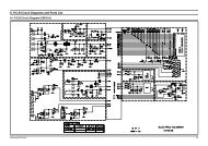
5. Schematic Diagrams<br />
5-1 Schematic Diagrams<br />
5-1<br />
POWER<br />
CORD<br />
230V/50HZ<br />
BRN BRN<br />
BLU<br />
GRILL<br />
TCO<br />
GRILL<br />
RELAY<br />
CAVITY<br />
TCO<br />
HEATER<br />
BLU<br />
WHT<br />
BLK<br />
BLU<br />
FUSE<br />
WHT<br />
CONDITION OF OVEN<br />
DOOR IS OPENED<br />
COOK OFF<br />
WIRING COLOR<br />
BRN : BROWN BLU : BLUE<br />
WHT : WHITE ORG : ORANGE<br />
RED : RED YEL : YELLOW<br />
BLK : BLACK<br />
Y/G : YELLOW GREEN<br />
BLK<br />
WHT<br />
250V10A<br />
C1<br />
ASSY CHOKE P.C.B<br />
1ND<br />
RESISTOR<br />
KEY BOARD<br />
C3<br />
C2<br />
NO<br />
COM<br />
L.V.T<br />
BLK<br />
BLK BLK<br />
PRIMARY LATCH<br />
SWITCH<br />
MAGNETRON<br />
FA<br />
BLK<br />
MGT<br />
TCO<br />
L.V.TRANS<br />
MAIN RELAY<br />
BLK<br />
NO<br />
COM<br />
L<br />
MAIN<br />
RELAY<br />
PRIMARYS/W<br />
POWER<br />
RELAY<br />
ORG<br />
ORG<br />
DOOR SENSING<br />
SWITCH<br />
FM<br />
A S S Y M A I N P.C.B<br />
F<br />
HIGH VOLTAGE<br />
TRANSFORMER<br />
BLK<br />
MONITOR FUSE<br />
(250V1.6A)<br />
RED<br />
RED<br />
230V40W<br />
YEL<br />
WHT<br />
COM<br />
BLK<br />
LAMP<br />
YEL<br />
F-MOTOR<br />
RED<br />
230V<br />
0V<br />
21V<br />
ORG<br />
BLK<br />
BLU<br />
WHT<br />
INRUSH<br />
RELAY<br />
ORG<br />
BLK<br />
DM<br />
D-MOTOR<br />
GRILL<br />
RELAY<br />
DOOR SENSING<br />
S/W<br />
NC WHT BLK<br />
COM NO<br />
BLK BLU<br />
BLK<br />
MONITOR<br />
SWITCH<br />
COM<br />
NC<br />
NO<br />
INRUSH RELAY<br />
RESISTOR<br />
BLU<br />
POWER RELAY<br />
(SECONDARY INTERLOCK)<br />
HIGH VOLTAGE<br />
DIODE<br />
YEL<br />
WHT<br />
HIGH VOLTAGE CAPACITOR<br />
RED<br />
H.V.FUSE<br />
H.V.TRANS<br />
BLK<br />
230V<br />
0V<br />
MAGNETRON<br />
SYMBOL COLOR<br />
BRN BROWN<br />
BLK BLACK<br />
RED RED<br />
BLU BLUE<br />
H.V.DIODE<br />
H.V.FUSE (0.8A)<br />
H.V.CAPACITOR<br />
F<br />
FA<br />
1.INPUT : 230V<br />
2.DOOR : OPEN<br />
3.LAMP : ON<br />
4. : P.C.B PATTERN<br />
5. : P.C.B IN/OUT POINT<br />
TO CHASSIS<br />
Samsung Electronics
ELECTRONICS<br />
© Samsung Electronics Co., Ltd. November 1998<br />
Printed in Korea<br />
DE68-62706B