4. Troubleshooting
4. Troubleshooting
4. Troubleshooting

Create successful ePaper yourself
Turn your PDF publications into a flip-book with our unique Google optimized e-Paper software.
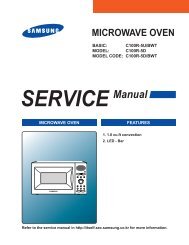
BASIC: M1736N<br />
MODEL: MW73VR<br />
MODEL CODE: MW73VR/BWT<br />
1. Precaution<br />
2. Product Specification<br />
3. Disassembly and Reassembly<br />
<strong>4.</strong> <strong>Troubleshooting</strong><br />
5. Exploded Views and Part List<br />
6. PCB Diagrams<br />
7. Wiring Diagrams<br />
8. Schematic Diagrams<br />
Refer to the service manual in the GSPN(see rear cover) for the more information.
• Contents<br />
1. Precaution . . . . . . . . . . . . . . . . . . . . . . . . . . . . . . . . . . . . . . . . . . . . . . . . . . . . . . . . . . . . . . . . . . . . . . . . . . . . . .3<br />
1-1 Safety precautions . . . . . . . . . . . . . . . . . . . . . . . . . . . . . . . . . . . . . . . . . . . . . . . . . . . . . . . . . . . . . . . . . . . . .4<br />
1-2 Special High Voltage Precautions . . . . . . . . . . . . . . . . . . . . . . . . . . . . . . . . . . . . . . . . . . . . . . . . . . . . . . . . .5<br />
2. Specifications . . . . . . . . . . . . . . . . . . . . . . . . . . . . . . . . . . . . . . . . . . . . . . . . . . . . . . . . . . . . . . . . . . . . . . . . . . .6<br />
2-1 Features . . . . . . . . . . . . . . . . . . . . . . . . . . . . . . . . . . . . . . . . . . . . . . . . . . . . . . . . . . . . . . . . . . . . . . . . . . . . .6<br />
2-2 Table of Specifications . . . . . . . . . . . . . . . . . . . . . . . . . . . . . . . . . . . . . . . . . . . . . . . . . . . . . . . . . . . . . . . . . .6<br />
2-3 Accessory . . . . . . . . . . . . . . . . . . . . . . . . . . . . . . . . . . . . . . . . . . . . . . . . . . . . . . . . . . . . . . . . . . . . . . . . . . . .7<br />
3. Disassembly and Reassembly . . . . . . . . . . . . . . . . . . . . . . . . . . . . . . . . . . . . . . . . . . . . . . . . . . . . . . . . . . . . . .8<br />
3-1 Disassembly of Magnetron, Motor Assembly and Lamp . . . . . . . . . . . . . . . . . . . . . . . . . . . . . . . . . . . . . . . .8<br />
3-2 Replacement of High Voltage Trancefomer . . . . . . . . . . . . . . . . . . . . . . . . . . . . . . . . . . . . . . . . . . . . . . . . .10<br />
3-3 Replacement of Door Assembly . . . . . . . . . . . . . . . . . . . . . . . . . . . . . . . . . . . . . . . . . . . . . . . . . . . . . . . . . .12<br />
3-4 Replacement of Drive Motor . . . . . . . . . . . . . . . . . . . . . . . . . . . . . . . . . . . . . . . . . . . . . . . . . . . . . . . . . . . .13<br />
3-5 Replacement of Control Circuit Board . . . . . . . . . . . . . . . . . . . . . . . . . . . . . . . . . . . . . . . . . . . . . . . . . . . . .14<br />
<strong>4.</strong> <strong>Troubleshooting</strong> . . . . . . . . . . . . . . . . . . . . . . . . . . . . . . . . . . . . . . . . . . . . . . . . . . . . . . . . . . . . . . . . . . . . . . . .15<br />
4-1 Error Code Numbering Rule . . . . . . . . . . . . . . . . . . . . . . . . . . . . . . . . . . . . . . . . . . . . . . . . . . . . . . . . . . . . .15<br />
4-2 Error Code List . . . . . . . . . . . . . . . . . . . . . . . . . . . . . . . . . . . . . . . . . . . . . . . . . . . . . . . . . . . . . . . . . . . . . . .15<br />
4-3 Electrical Malfunction . . . . . . . . . . . . . . . . . . . . . . . . . . . . . . . . . . . . . . . . . . . . . . . . . . . . . . . . . . . . . . . . . .17<br />
5. Exploded Views and Parts List . . . . . . . . . . . . . . . . . . . . . . . . . . . . . . . . . . . . . . . . . . . . . . . . . . . . . . . . . . . .33<br />
5-1 Exploded Views . . . . . . . . . . . . . . . . . . . . . . . . . . . . . . . . . . . . . . . . . . . . . . . . . . . . . . . . . . . . . . . . . . . . . .33<br />
5-2 Main Parts List . . . . . . . . . . . . . . . . . . . . . . . . . . . . . . . . . . . . . . . . . . . . . . . . . . . . . . . . . . . . . . . . . . . . . . .34<br />
5-3 Door Parts List . . . . . . . . . . . . . . . . . . . . . . . . . . . . . . . . . . . . . . . . . . . . . . . . . . . . . . . . . . . . . . . . . . . . . . .35<br />
5-4 Control Parts List . . . . . . . . . . . . . . . . . . . . . . . . . . . . . . . . . . . . . . . . . . . . . . . . . . . . . . . . . . . . . . . . . . . . .36<br />
5-5 Standard Parts List . . . . . . . . . . . . . . . . . . . . . . . . . . . . . . . . . . . . . . . . . . . . . . . . . . . . . . . . . . . . . . . . . . . .37<br />
6. PCB Diagrams . . . . . . . . . . . . . . . . . . . . . . . . . . . . . . . . . . . . . . . . . . . . . . . . . . . . . . . . . . . . . . . . . . . . . . . . . .38<br />
6-1 PCB Diagrams . . . . . . . . . . . . . . . . . . . . . . . . . . . . . . . . . . . . . . . . . . . . . . . . . . . . . . . . . . . . . . . . . . . . . . .38<br />
7. Wiring Diagrams . . . . . . . . . . . . . . . . . . . . . . . . . . . . . . . . . . . . . . . . . . . . . . . . . . . . . . . . . . . . . . . . . . . . . . . .39<br />
7-1 Wiring Diagrams . . . . . . . . . . . . . . . . . . . . . . . . . . . . . . . . . . . . . . . . . . . . . . . . . . . . . . . . . . . . . . . . . . . . . .39<br />
8. Schematic Diagrams . . . . . . . . . . . . . . . . . . . . . . . . . . . . . . . . . . . . . . . . . . . . . . . . . . . . . . . . . . . . . . . . . . . . .41<br />
8-1 Schematic Diagrams . . . . . . . . . . . . . . . . . . . . . . . . . . . . . . . . . . . . . . . . . . . . . . . . . . . . . . . . . . . . . . . . . .41
1. Precaution<br />
3
1. Precaution<br />
Follow these special safety precautions . Although the microwave oven is completely safe during ordinary use,<br />
repair work can be extremely hazardous due to possible exposure to microwave radiation, as well as potentially<br />
lethal high voltages and currents .<br />
1-1 Safety precautions ( )<br />
1. All repairs should be done in accordance with the<br />
procedures described in this manual . This product<br />
complies with Federal Performance Standard 21<br />
CFR<br />
. Microwave emission check should be performed to<br />
prior to servicing if the oven is operative .<br />
3. If the oven operates with the door open :Instruct<br />
the user not to operate the oven and contact<br />
the manufacturer and the center for devices and<br />
radiological health immediately .<br />
<strong>4.</strong> Notify the Central Service Center if the microwave<br />
leakage exceeds 5 mW/cm2 .<br />
5. Check all grounds .<br />
6. Do not power the MWO from a “2-prong” AC cord .<br />
Be sure that all of the built-in protective devices are<br />
replaced . Restore any missing protective shields .<br />
7. When reinstalling the chassis and its assemblies,<br />
be sure to restore all protective devices, including:<br />
nonmetallic control knobs and compartment covers .<br />
8. Make sure that there are no cabinet openings<br />
through which people --particularly children--might<br />
insert objects and contact dangerous voltages .<br />
Examples: Lamp hole,ventilation slots .<br />
9. Inform the manufacturer of any oven foundto have<br />
emission in excess of 5 mW/cm2 ,Make repairs to<br />
bring the unit into compliance at no cost to owner<br />
and try to determine cause . Instruct owner not to use<br />
oven until it has been brought into compliance .<br />
CENTRAL SERVICE CENTER<br />
10. Service technicians should remove their watches<br />
while repairing an MWO .<br />
11. To avoid any possible radiation hazard,replace parts<br />
in accordance with the wiring diagram . Also, use<br />
only the exact replacements for the following parts:<br />
Primary and secondary interlock switches, interlock<br />
monitor switch .<br />
1 . If the fuse is blown by the Interlock Monitor Switch:<br />
Replace all of the following at the same time:<br />
Primary, door sensing switch and power relay, as<br />
well as the Interlock Monitor Switch . The correct<br />
adjustment of these switches is described elsewhere<br />
in this manual . Make sure that the fuse has the<br />
correct rating for the particular model being repaired .<br />
4<br />
13. Design Alteration Warning: Use exact replacement<br />
parts only, i.e.,only those that are specified in<br />
thedrawings and parts lists of this manual . This<br />
is especially important for the Interlock switches,<br />
described above . Never alter or add to the<br />
mechanical or electrical design of the MWO .<br />
Any design changes or additions will void the<br />
manufacturer’s warranty . Always unplug the unit’s<br />
AC power cord from the AC power source before<br />
attempting to remove or reinstall any component or<br />
assembly .<br />
1<strong>4.</strong> Never defeat any of the B+ voltage interlocks . Do not<br />
apply AC power to the unit (or any of its assemblies)<br />
unless all solid-state heat sinks are correctly<br />
installed .<br />
15. Some semiconductor (“solid state”) devices<br />
are easily damaged by static electricity . Such<br />
components are called Electrostatically Sensitive<br />
Devices (ESDs) . Examples include integrated<br />
circuits and field-effect transistors. Immediately<br />
before handling any semiconductor components or<br />
assemblies, drain the electrostatic charge from your<br />
body by touching a known earth ground .<br />
16. Always connect a test instrument’s ground lead to<br />
the instrument chassis ground before connecting the<br />
positive lead; always remove the instrument’s ground<br />
lead last .<br />
17. When checking the continuity of the witches or<br />
transformer, always make sure that the power is<br />
OFF, and one of the lead wires is disconnected .<br />
18. Components that are critical for safety are indicated<br />
in the circuit diagram by shading, or .<br />
19. Use replacement components that have the same<br />
ratings, especially for flame resistance and dielectric<br />
strength specifications. A replacement part that does<br />
not have the same safety characteristics as the<br />
original might create shock, fire or other hazards.<br />
NOTE : Connect the oven to a 20A . When<br />
connecting the oven to a 15A,make sure that circuit<br />
breaker can operate .
1. Precaution<br />
1- Special High Voltage Precautions<br />
1. High Voltage Warning Do not attempt to measure any of<br />
the high voltages --this includes the filament voltage of the<br />
magnetron . High voltage is present during any cook cycle .<br />
Before touching any components or wiring, always unplug<br />
the oven and discharge the high voltage capacitor (See<br />
Figure 1-1)<br />
. The high-voltage capacitor remains charged about 30<br />
seconds after disconnection . Short the negative terminal<br />
of the high-voltage capacitor to to the oven chassis . (Use a<br />
screwdriver .)<br />
3. High voltage is maintained within specified limits by closetolerance,<br />
safety-related components and adjustments . If<br />
the high voltage exceeds the specified limits, check each<br />
of the special components .<br />
PRECAUTION<br />
5<br />
H . V . Capacitor<br />
Short<br />
H . V . Diode<br />
There exists HIGH VOLTAGE ELECTRICITY with high current capabilities in the circuits of the HIGH<br />
VOLTAGE TRANSFORMER secondary and filament terminals. It is extremely dangerous to work on or<br />
near these circuits with the oven energized .<br />
DO NOT measure the voltage in the high voltage circuit including filament voltage of magnetron.<br />
PRECAUTION<br />
Servicemen should remove their watches whenever working close to or replacing the magnetron .<br />
PRECAUTION<br />
Never touch any circuit wiring with your hand nor with uninsulated tool during operation .
2. Specifications<br />
-1 Features<br />
- Handle Design<br />
- Tact & Menbrane Control Panel<br />
- 0L Compact Size MWO<br />
2-2 Table of Specifications<br />
Items<br />
Product Features<br />
6<br />
Model<br />
Model Basic Model New<br />
MODEL NAME M1736N MW73VR<br />
Power Source 230V ~ 50Hz AC 230V ~ 50Hz AC<br />
Power consumption Microwave 1300W 1150W<br />
Output Power 100W / 800W (IEC-705) 100W / 800W (IEC-705)<br />
Operating Frequency 2450MHz 2450MHz<br />
Magnetron OM75S(31) OM75S(31)<br />
Cooling Method Cooling fan motor Cooling fan motor<br />
Dimensions<br />
(W x H x D)<br />
Outside 489 x 275 x 361mm 489 x 275 x 361mm<br />
Oven cavity 306 x 211 x 320mm 306 x 211 x 320mm<br />
Volume 20Liter 20Liter<br />
Weight Net 12 .5Kg 12 .5Kg
2. Specifications<br />
-3 Accessory<br />
Item Description Code No. Q’ty<br />
Coupler DE67-00140A 1<br />
Assy-Guide Roller DE97-00193B 1<br />
Tray-cooking DE74-00027A 1<br />
7
3. Disassembly and Reassembly<br />
3-1 Disassembly of Magnetron, Motor Assembly and Lamp<br />
Remove the magnetron including the shield case, permanent magnet, choke coils and capacitors (all of which<br />
are contained in one assembly)<br />
Parts Explaination Photo Explaination<br />
Magnetron,<br />
Motor Assembly<br />
and Lamp<br />
8<br />
1. Disconnect all lead wires from<br />
the magnetron and lamp .<br />
. Remove a screw securing air<br />
cover .<br />
3. Remove the air cover .
3. Disassembly and Reassembly<br />
3-1 Disassembly of Magnetron, Motor Assembly and Lamp<br />
Parts Explaination Photo Explaination<br />
Magnetron,<br />
Motor Assembly<br />
and Lamp<br />
9<br />
<strong>4.</strong> Remove screws securing the<br />
magnetron to the wave guide .<br />
5. Take out the magnetron very<br />
carefully .<br />
6. Remove two screws from the<br />
back panel .<br />
7. Take out the fan motor .
3. Disassembly and Reassembly<br />
3-1 Disassembly of Magnetron, Motor Assembly and Lamp<br />
Parts Explaination Photo Explaination<br />
Magnetron,<br />
Motor Assembly<br />
and Lamp<br />
10<br />
8. Remove the oven lamp from<br />
hole of air cover .<br />
NOTE1: When removing the magnetron, make sure that its antenna does not hit any adjacent parts, or it may be<br />
damaged .<br />
NOTE : When replacing the magnetron, be sure to remount the magnetron gasket in the correct position and<br />
make sure the gasket is in good condition .<br />
3- Replacement of High Voltage Trancefomer<br />
High Voltage<br />
Transformer<br />
Parts Explaination Photo Explaination<br />
1. Discharge the high voltage<br />
capacitor .<br />
. Disconnect all the leads .
3. Disassembly and Reassembly<br />
3- Replacement of High Voltage Trancefomer<br />
High Voltage<br />
Transformer<br />
Parts Explaination Photo Explaination<br />
PRECAUTION<br />
11<br />
3. Remove the mounting bolts .<br />
<strong>4.</strong> Replace the High Voltage<br />
Transformer<br />
5. After replace, reconnect the<br />
leads correctly and firmly.<br />
Servicemen should remove their watches whenever working close to or replacing the magnetron .<br />
PRECAUTION<br />
There exists HIGH VOLTAGE ELECTRICITY with high current capabilities in the circuits of the<br />
HIGHVOLTAGE TRANSFORMER secondary and filament terminals. It is extremely dangerous to work on<br />
or near these circuits with the oven energized .<br />
DO NOT measure the voltage in the high voltage circuit including filament voltage of magnetron.
3. Disassembly and Reassembly<br />
3-3 Replacement of Door Assembly<br />
Parts Disassembly Photo Explaination<br />
Removal of<br />
Door “C”<br />
Removal<br />
of Door<br />
Assembly<br />
Removal of<br />
Door “E”<br />
Removal of<br />
Key Door &<br />
Spring<br />
1<br />
Insert flat screwdriver into the gap<br />
between Door “A” and Door “C” to remove<br />
Door “C” . Be careful when handling Door<br />
“C” because it is fragile .Then remove the<br />
door assembly .<br />
Lift up the Door Assembly from Cavity .<br />
Following the procedure as shown in the<br />
figure, insert and bend a thin metal plate<br />
between Door “E” and Door “A” until you<br />
hear the ‘tick’ sound .<br />
• Insertion depth of the thin metal plate<br />
should be 0 .5mm or less .<br />
Remove pin hinge from Door “E”<br />
Detach spring from Door “E” and key door .
3. Disassembly and Reassembly<br />
3-4 Replacement of Drive Motor<br />
Drive Motor<br />
Drive Motor<br />
Parts Explaination Photo Explaination<br />
COVER FIXING SCREW :<br />
MATCHINE SCREW(6006-001170)<br />
13<br />
1. Take out the glass tray,<br />
guide roller from oven cavity,<br />
disconnect power .<br />
. Remove turn table motor cover<br />
from case bottom .<br />
CAUTION : Remove sharp edge<br />
after cover removal .<br />
3. Disconnect leads from motor .<br />
<strong>4.</strong> Remove the screws securing<br />
motor to bottom of over cavity .<br />
6. Lift out the motor .<br />
5. When replacing the motor, be<br />
sure to remount it in the correct<br />
position .<br />
NOTE : The shaft of motor should<br />
fit tip coupler.<br />
6. When reassemble a drive<br />
motor cover . give a turn in a<br />
180° and fix with a screw.<br />
NOTE : Bring the spare screw<br />
from service center .
3. Disassembly and Reassembly<br />
3-5 Replacement of Control Circuit Board<br />
Removal of<br />
Control Box<br />
Assembly<br />
Parts Explaination Photo Explaination<br />
Removal of Ass’y<br />
P .C .B Assembly<br />
Removal of<br />
Window Display<br />
& Membrane<br />
Panel<br />
Control Box<br />
ASSY PCB<br />
Control Panel<br />
14<br />
Screw<br />
SCREWS<br />
1. Be sure to ground any static electric<br />
charge in your body and never touch<br />
the control circuit .<br />
. Disconnect the connectors from the<br />
control circuit board .<br />
3. Remove screws securing the control<br />
box assembly .<br />
<strong>4.</strong> Remove the screw securing the<br />
ground tail of the keyboard .<br />
1. Pull the lever end of the plastic<br />
fastener and remove the Flexible<br />
Printed Circuit(FPC) of membrane<br />
panel .<br />
. Remove screws securing the control<br />
circuit<br />
board .<br />
3. Lift up the control circuit board from<br />
the Ass’y control box .<br />
<strong>4.</strong> When reconnecting the FPC<br />
connector, make sure that the<br />
holes on the connector are properly<br />
engaged with the hooks on the<br />
Plastic Fastener .<br />
1. Window display should not be<br />
disassembled as its mounting tabs<br />
will be broken . If repair work is<br />
difficult, replace with Ass’y control<br />
panel .<br />
. The membrane key board is<br />
attached to the escutcheon base<br />
with double faced adhesive tape .<br />
Therefore, applying hot air such as<br />
using of hair dryer is recommended<br />
for smoother removal .<br />
3. When installing new membrane key<br />
board, make sure that the surface<br />
of escutcheon base is cleaned<br />
sufficiently so that any problems<br />
(shorted contacts or uneven surface)<br />
can be avoided .
<strong>4.</strong> <strong>Troubleshooting</strong><br />
4-1 Error Code Numbering Rule<br />
1. ERROR CODE NUMBERING RULE is applied to a microwave oven and an oven .(CMO, OTR, Grill, Convection,<br />
Commercial etc .)<br />
. All sensors and devices have their own number . ex) Gas Sensor = 1, Temp . Sensor = 2, . . .<br />
3. Of each device, No .1 and No .2 refer to “Open Error” (not sensed) and “Short Error”, respectively .<br />
<strong>4.</strong> This numbering rule has been applied to models to have been developed since January, 1, 2005 . (But, GE or<br />
Customize model are excluded .)<br />
4- Error Code List<br />
Gas Sensor<br />
Error<br />
Code<br />
Gas Sensor Error<br />
Case (E-1X)<br />
DEVICE ERROR CASE<br />
0- Others 1- Open<br />
1- Gas Sensor 2- Short<br />
2- Temp . Sensor •<br />
3- Weight Sensor •<br />
4- Easy/PH Sensor •<br />
5- EEPROM<br />
•<br />
•<br />
•<br />
15<br />
Solution Page<br />
E-11 Open<br />
17 Page<br />
E-12 Short<br />
Check Sensor part ,connection of sensor housing and PCB’s<br />
18 Page<br />
connector .<br />
E-13 T1 Max Time Error<br />
19 Page<br />
E-14 Dry Up / No Load Insert food and restart .<br />
Temp Sensor<br />
Error<br />
Code<br />
Temp. Sensor Error Case (E- X) Solution Page<br />
E-21 Open Check sensor part and connection of sensor 17 Page<br />
E-22 Short housing and PCB’s connector .<br />
18 Page<br />
E-23<br />
T1 Max Time Error (Preheating not<br />
completed) Check heater .<br />
25 Page<br />
E-24 Over temperature error 27 Page<br />
E-25<br />
In case abnormal temperature is<br />
sensed at Micro Cook<br />
In case the temperature is not over<br />
Cool down set and restart . 28 Page<br />
E-26 the fixed AD in first 3 minutes after<br />
cooking by heater starts .<br />
Check sensor and heater . 25 Page<br />
Eeprom Error<br />
Error Code EEPROM Error Case (E-5X) Solution Page<br />
E-51 Open (Sense Failure)<br />
E-53 Read/Write Error<br />
Replace EEPROM and restart . 24 Page<br />
E-54 Zero not to be set
<strong>4.</strong> <strong>Troubleshooting</strong><br />
Weight Sensor<br />
Error<br />
Code<br />
Gas Sensor Error Case (E-1X) Solution Page<br />
E-31 Open (When value of HEX is above “FF” for 5 seconds)<br />
17 Page<br />
E-32 Short 18 Page<br />
E-33<br />
In case the initial value of HEX is under “14” for 30<br />
seconds while a weight sensor in operation .<br />
Check Sensor .<br />
E-34<br />
In case the initial value of K calculated by a weight<br />
sensor is above and under “±28” as value of HEX .<br />
21 Page<br />
E-35 In case the value of A is “-” as a weight sensor calculates .<br />
E-36 In case the door opens during sensor cooking .<br />
Cancel the present mode and<br />
restart from the begining .<br />
22 Page<br />
Easy/Ph Sensor<br />
Error<br />
Code<br />
E-41 Open<br />
E-42 Short<br />
Easy/PH Sensor Error Case (E4) Solution Page<br />
Check Sensor .<br />
16<br />
17 Page<br />
18 Page<br />
E-43 T1 Max Time Error 19 Page<br />
E-44 Dry Up Insert food and restart . 19 Page<br />
E-45 Cooling Error (3minutes) Remove moisture from sensor and restart . 23 Page<br />
E-46 Primary Open Error(3minutes) Check Sensor . 17 Page<br />
E-47 The door opens during cooking<br />
Cancel the present mode and restart from the<br />
begining .<br />
22 Page<br />
Humidity Sensor<br />
Error Code Humidity Sensor Error Case (E-6X) Solution Page<br />
E-61 Open<br />
17 Page<br />
E-62 Short Check Sensor .<br />
18 Page<br />
E-63<br />
Others<br />
T1 Max Time Error 19 Page<br />
Error<br />
Code<br />
Others (E-0X, Letter) Solution Page<br />
-SE- Key Short Error (10 seconds) Turn off set and restart . 20 Page<br />
E-02 Cooking Time Setting Over Error (MWO)<br />
E-03 Cooking Time Setting Over Error (Grill)<br />
E-04<br />
Cooking Time Setting Over Error<br />
(Convection)<br />
Check each mode’s setting time . 26 Page<br />
E-05<br />
Cooking Time Setting Over Error<br />
(Combination)<br />
E-06<br />
It fails to sense that the swing heater has<br />
stopped for 20 seconds during cooking .<br />
Check Swing heater’s motor and connector . 29 Page
<strong>4.</strong> <strong>Troubleshooting</strong><br />
4-3 Electrical Malfunction<br />
4-3-1 Sensor Open Error<br />
Connect the sensor.<br />
NO<br />
Connect the<br />
wire properly.<br />
S/W Error<br />
YES<br />
“E-11, E-21, E-31, E-41, E-46, E-61” is displayed.<br />
YES<br />
NO<br />
After Power -> On, does<br />
the symptom continue?<br />
Replace the PCB.<br />
Is the sensor disconnected?<br />
NO<br />
Is the sensor wire<br />
connected properly?<br />
YES<br />
Does the voltage change<br />
as the humidity, temperature<br />
and weight change?<br />
NO<br />
The sensor is out of order.<br />
Replace the sensor.<br />
Perform the operation again and check if it<br />
is working properly.<br />
17<br />
: Check if the sensor housing<br />
is inserted into the connector<br />
of the main PCB.<br />
: Check if the sensor wire is damaged, if the<br />
housing is loose and if the sensor and the<br />
wire are properly connected.<br />
: Check if the voltage of the GND and sensor<br />
changes using a digital multi-meter<br />
by forcefully changing the humidity, temperature<br />
and weight.
<strong>4.</strong> <strong>Troubleshooting</strong><br />
4-3- Sensor Short Error<br />
Remove the shorted part<br />
of the temperature sensor.<br />
Remove any foreign<br />
Substance from the<br />
shorted part.<br />
NO<br />
S/W Error<br />
YES<br />
YES<br />
YES<br />
After Power > On, does<br />
the symptom continue?<br />
YES<br />
Replace the PCB.<br />
“E-12, E-22,E-32, E-42, or E-62” is displayed.<br />
Is the sensor shorted?<br />
NO<br />
Is the sensor terminal part<br />
of the PCB shorted?<br />
NO<br />
Does the voltage change<br />
as the humidity, temperature<br />
and weight cha<br />
NO<br />
The sensor is out of order.<br />
Replace the sensor.<br />
Perform the operation again and<br />
check if it is working properly.<br />
18<br />
: Check if both terminals of the<br />
sensor are slightly shorted.<br />
: Check if the sensor and related<br />
parts such as the connector or<br />
soldering parts are slightly shorted.<br />
: Check if the voltage of the GND and<br />
sensor changes using a digital multi-meter<br />
by forcefully changing the humidity,<br />
temperature and weight.
<strong>4.</strong> <strong>Troubleshooting</strong><br />
4-3-3 Sensor Max Time Error<br />
Insert food<br />
and heat it again.<br />
Place food with<br />
moisture into it and<br />
heat it again.<br />
Remove the an<br />
foreign substance<br />
or obstacle.<br />
“E-13, E-14, E-43, E-44, E-63” is displayed..<br />
YES<br />
YES<br />
YES<br />
Does it heat up without<br />
placing food into it?<br />
NO<br />
Does it heat with completely<br />
dried food?<br />
NO<br />
Is any foreign substance<br />
on the sensor or is something acting as an<br />
obstacle in front of the sensor?<br />
NO<br />
The sensor is out of order.<br />
Replace the sensor.<br />
Perform the operation again and check if it<br />
is working properly.<br />
19<br />
: Since heating without placing food into<br />
the oven may damage the product, take care.<br />
: Since heating completely dried food<br />
may burn the food, take care.<br />
: If the sensor is contaminated by a foreign<br />
substance, it may fail to detect the humidity.
<strong>4.</strong> <strong>Troubleshooting</strong><br />
4-3-4 Key Short Error<br />
The membrane<br />
is defective.<br />
Replace the<br />
Control Panel.<br />
YES<br />
YES<br />
YES<br />
NO<br />
0<br />
“- SE -” is displayed.<br />
Is the key not recognized<br />
at all?<br />
NO<br />
Is the key recognized<br />
intermittently?<br />
NO<br />
Is a specific key<br />
not recognized?<br />
NO<br />
S/W Error<br />
After Power > On,<br />
does the symptom continue?<br />
YES<br />
Replace the PCB.<br />
Perform the operation again and check if it<br />
is working properly.
<strong>4.</strong> <strong>Troubleshooting</strong><br />
4-3-5 Weight Sensor Error<br />
Place the turntable over<br />
the roller properly.<br />
NO<br />
Remove the foreign<br />
substance.<br />
Place the food<br />
in the center.<br />
YES<br />
YES<br />
“E-33, E-34 or E-35” is displayed.<br />
Has the turntable<br />
been placed over the roller<br />
properly?<br />
YES<br />
Is the weight sensor<br />
contaminated by any foreign<br />
substance?<br />
NO<br />
Does the roller turn<br />
and press against the<br />
weight sensor?<br />
NO<br />
The sensor is out of order.<br />
Replace the sensor.<br />
Perform the operation again and check if it<br />
is working properly.<br />
1<br />
: Check if the turntable turns abnormally<br />
because food is placed on one side<br />
only, or if it turns irregularly,<br />
or if it is slanted and the<br />
weight sensor is not pressed.
<strong>4.</strong> <strong>Troubleshooting</strong><br />
4-3-6 Weight Sensor Error<br />
Close the door.<br />
Check the Door S/W<br />
and the housing.<br />
YES<br />
NO<br />
NO<br />
“E-36 or E-47” is displayed.<br />
Was the door open during<br />
the operation?<br />
NO<br />
Is the door sensing part normal?<br />
S/W Error<br />
YES<br />
After Power > On,<br />
does the symptom continue?<br />
YES<br />
Replace the PCB.<br />
Perform the operation again and check if it<br />
is working properly.<br />
: Check the housing connected to<br />
the door S/W and PCB and if it is<br />
opened or shorted intermittently.
<strong>4.</strong> <strong>Troubleshooting</strong><br />
4-3-7 Cooling Error<br />
Remove any moisture<br />
of the sensor.<br />
Check the sensor<br />
terminal and housing.<br />
Replace<br />
the sensor.<br />
YES<br />
YES<br />
NO<br />
NO<br />
“E-45” is displayed.<br />
Is the sensor wet?<br />
NO<br />
Is the sensor voltage over 3V?<br />
NO<br />
Does the same symptom<br />
continue after replacing<br />
the sensor?<br />
S/W Error<br />
YES<br />
After Power > On,<br />
does the symptom continue?<br />
YES<br />
Replace the PCB.<br />
Perform the operation again and check if it<br />
is working properly.<br />
3<br />
: To remove moisture from the sensor,<br />
open the door for 5 minutes.<br />
: Check if the GND and sensor terminal<br />
is maintained over 3V continuously during<br />
the initial cooking course using a multimeter.
<strong>4.</strong> <strong>Troubleshooting</strong><br />
4-3-8 EEPROM Error<br />
Insert and solder<br />
an EEPROM<br />
Replace the<br />
EEPROM and repair<br />
the short circuit.<br />
NO<br />
YES<br />
YES<br />
“E-51, E-53, or E-54” is displayed.<br />
NO<br />
EEPROM이 Has the EEPROM 삽입 been 되었는가? inserted?<br />
YES<br />
Is EEPROM the EEPROM 단자가 terminal Open/Short opened or<br />
is there 되었는가? a short-circuit?<br />
NO<br />
EEPROM Defect<br />
Replace the EEPROM<br />
Does it work properly?<br />
NO<br />
S/W Error<br />
S/W 오동작<br />
After Power > On,<br />
does the symptom continue?<br />
YES<br />
Replace the PCB.<br />
Perform the operation again and check if it<br />
is working properly.<br />
4<br />
: An R4LCO40 or 24LCO4 EEPROM<br />
is to be used. Check if a proper EEPROM<br />
has been installed.
<strong>4.</strong> <strong>Troubleshooting</strong><br />
4-3-9 Preheating Error<br />
Check the heater<br />
related drive part.<br />
Replace the<br />
heater.<br />
Reconnect the<br />
temperature<br />
sensor properly.<br />
Replace the<br />
heater.<br />
NO<br />
YES<br />
NO<br />
YES<br />
NO<br />
“E-23, E-26” is displayed.<br />
Does the heater work?<br />
5<br />
YES<br />
Is the heater temperature<br />
very low?<br />
NO<br />
Is the temperature sensor<br />
connected properly?<br />
YES<br />
Is the resistance<br />
between the heater terminals<br />
more then a few MΩ?<br />
NO<br />
S/W Error<br />
After Power > On,<br />
does the symptom continue?<br />
YES<br />
Replace the PCB.<br />
Perform the operation again and check if it<br />
is working properly.<br />
: Check the voltages of<br />
both heater terminals.<br />
: After operating the heater for more then<br />
10 minutes check if the heater temperature<br />
remains low.<br />
: A normal heater’s resistance is a few Ω.<br />
A short circuit increases the resistance<br />
to a few MΩ.
<strong>4.</strong> <strong>Troubleshooting</strong><br />
4-3-10 Cooking Time Over Selection Error<br />
NO<br />
Over Time is<br />
set?<br />
YES<br />
An “E-02” error<br />
occurred.<br />
YES<br />
“E-02, E-03, E-04, or E-05” is displayed.<br />
YES<br />
Over Time is<br />
set?<br />
YES<br />
An “E-05” error<br />
occurred.<br />
Press the Cancel<br />
key to cancel the<br />
current state.<br />
Is this<br />
happening during<br />
the MW operation?<br />
NO<br />
NO<br />
Is it<br />
happening during<br />
the Grill operation?<br />
NO<br />
Is it<br />
happening during<br />
the Convection<br />
operation?<br />
NO<br />
Is it<br />
happening during<br />
the Combination<br />
operation?<br />
NO<br />
Repeat the operation and check<br />
if it is working properly.<br />
6<br />
NO<br />
YES<br />
YES<br />
Over Time is<br />
set?<br />
YES<br />
An “E-04” error<br />
occurred.<br />
Press the Cancel<br />
key to cancel the<br />
current state.<br />
Ex)<br />
Over Time is<br />
set?<br />
YES<br />
An “E-03” error<br />
occurred.<br />
: Since the max. time may differ<br />
depending on the model,<br />
refer to the IB<br />
For example,<br />
MW Mode<br />
Max Time<br />
Grill 60 mins<br />
Convection<br />
Conbination<br />
45 mins<br />
45 mins
<strong>4.</strong> <strong>Troubleshooting</strong><br />
4-3-11 Internal Oven Temperature Abnormal Error<br />
Reconnect the<br />
temperature<br />
sensor properly.<br />
Check<br />
히터 구동부를<br />
and repair<br />
the heater<br />
점검 drive 수리한다 part if<br />
necessary.<br />
NO<br />
NO<br />
“E-09, “E-24” E-24, error E-0A” code 가 표시된다 is displayed.<br />
NO<br />
7<br />
Is the temperature NO sensor<br />
connectivity normal?<br />
YES<br />
Is the temperature sensor<br />
connectivity normal?<br />
YES<br />
S/W Error<br />
After Power > On,<br />
does the symptom<br />
continue?<br />
YES<br />
Replace the PCB.<br />
Perform the operation again and check<br />
if it is working properly
<strong>4.</strong> <strong>Troubleshooting</strong><br />
4-3-1 Swing Heater Detection Error<br />
Press the Cancel<br />
key to cancel the<br />
current state.<br />
An “E-25” error<br />
occurred.<br />
Press the Cancel key.<br />
Connect it<br />
properly<br />
and try again.<br />
YES<br />
NO<br />
NO<br />
8<br />
An “E-25” error occurred.<br />
Is the oven in MW mode?<br />
YES<br />
Is the internal temperature<br />
over 200 degrees?<br />
NO<br />
Is the sensor connectivity<br />
normal?<br />
YES<br />
S/W Error<br />
After Power > On,<br />
does the symptom continue?<br />
YES<br />
Replace the PCB.<br />
Perform the operation again and check if it<br />
is working properly.<br />
NO
<strong>4.</strong> <strong>Troubleshooting</strong><br />
4-3-13 Swing Heater Detection Error<br />
NO<br />
After waiting for 20 seconds,<br />
check if the micro-switch has<br />
been detected.<br />
NO<br />
NO<br />
An “E-06” error code is displayed.<br />
Is the oven in<br />
Bake Toast mode?<br />
YES<br />
Has the switch heater<br />
operated for 20 seconds?<br />
YES<br />
Has the micro-switch<br />
been detected?<br />
YES<br />
Is connectivity housing<br />
of the micro-switch normal?<br />
9<br />
YES<br />
S/W Error<br />
After Power > On,<br />
does the symptom continue?<br />
YES<br />
Replace the PCB.<br />
Perform the operation again and<br />
check if it is working properly.<br />
NO<br />
NO<br />
The micro-switch is<br />
defective Replace it.<br />
Connect the<br />
micro-switch properly.
<strong>4.</strong> <strong>Troubleshooting</strong><br />
4-3-14 If oven malfunction<br />
Oven does not operate.<br />
Is Fuse OK?<br />
YES<br />
Is the magnetron<br />
temperature switch normal?<br />
YES<br />
Is SMPS power supply<br />
cirduit normal?<br />
YES<br />
Is the IC01 output of<br />
PCB normal?<br />
YES<br />
Checking high<br />
voltagecircuts<br />
*Inspection method<br />
NO Is Primary interlock<br />
switch normal?<br />
NO<br />
NO<br />
NO<br />
NO<br />
YES<br />
Is Power Relay normal?<br />
Replace switch<br />
Do check power supply<br />
circuit<br />
Do check<br />
Relay control circuit<br />
Is high voltage dioed<br />
normal?<br />
Is high voltage dioed<br />
normal?<br />
YES<br />
Is high voltage<br />
capacitor normal?<br />
YES<br />
Is magnetron normal?<br />
30<br />
NO<br />
NO<br />
NO<br />
NO<br />
NO<br />
NO<br />
NO<br />
Power supply circuit check point<br />
Relay control circuit check point
<strong>4.</strong> <strong>Troubleshooting</strong><br />
4-3-15 If button malfunction<br />
Buttons of the control panel do not work. *Inspection method<br />
Are button pressed<br />
in the correct order?<br />
YES<br />
Is the connector of the<br />
control panel normal?<br />
YES<br />
Replace PCB.<br />
NO<br />
NO<br />
Menbrane type<br />
Refer to User Manual<br />
Tact type<br />
31
<strong>4.</strong> <strong>Troubleshooting</strong><br />
4-3-16 If food is not heated even though an oven works<br />
Food is not heated even though an oven works. *Inspection method<br />
Is the latch switch<br />
operating normally?<br />
YES<br />
Checking high voltage circuits<br />
NO<br />
Method to control latch switch<br />
3
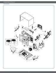
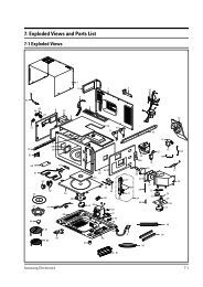
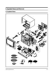
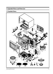
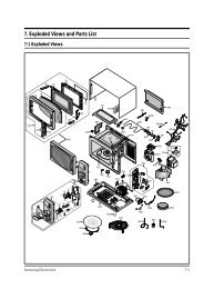
5. Exploded Views and Parts List<br />
5-1 Exploded Views<br />
M048<br />
M038<br />
T001<br />
T017<br />
M034<br />
M051<br />
M047<br />
M001<br />
M049<br />
M039<br />
M042<br />
M040<br />
Z778<br />
M099<br />
B018<br />
M041<br />
33<br />
M015<br />
B001<br />
H018<br />
B006<br />
M036<br />
B001<br />
M020<br />
M023<br />
B002<br />
B009<br />
M037<br />
M019<br />
M022<br />
M017<br />
M035<br />
W002
5. Exploded Views and Parts List<br />
5- Main Parts List<br />
(S.N.A : SERVICE NOT AVAILABLE)<br />
Level No. Code No. Description Specification Q’ty SA/<br />
SNA<br />
1-1 M041 0402-001554 HVDIODE-RECTIFIER HV03-12T01,12000V,0 .4A 1 SA -<br />
1-1 M039 2501-001016 C-OIL 950nF,2 .1KV,BK,35x54x80,20mm 1 SA -<br />
1-1 M036 4713-001046 LAMP-INCANDESCENT 240V,104mA,25W,ORG,-,- 1 SA -<br />
1-1 M038 DE26-00099A TRANS H .V SHV-EURO1-1,230V,50HZ,2330V,3 . 1 SA -<br />
1-1 M049 DE31-10154A MOTOR SYNCHRONOUS M2HJ49ZR02,ST-16,50/60 1 SA -<br />
1-1 Z778 DE47-20008A THERMOSTAT PW2N-52JC,100/60,250V/7 .5A,H, 1 SA -<br />
1-1 M040 DE61-00139A BRACKET-HVC NC2000,SECC,T0 .8,-,-,-,0 .6/0 1 SA -<br />
1-1 M047 DE61-40066A FOOT -,PP,-,BLK,-,-,- 1 SA -<br />
1-1 M001 DE64-00350K PANEL-OUTER MGB 22 C/STEEL,T0 .5GE-WHT 1 SA -<br />
1-1 M099 DE66-90113A LEVER-DOOR PP(TB53-GH41),T2 .5,-,-,12g,NT 1 SA -<br />
1-1 M034 DE67-00140A COUPLER PPS,(ESS840),3G,BRN,NEW 1 SA -<br />
1-1 M022 DE71-00148A COVER-BLOWER PP,T1 .5NTR MW850WA NC2000 1 SA -<br />
1-1 M051 DE71-00151A COVER MGT PP,T2,W54,L129,GE-WHTMW850WA 1 SA -<br />
1-1 M037 DE71-60457C COVER-AIR 3RD-0 .7(BTM),PP(FB53 G30),-,-, 1 SA -<br />
1-1 T001 DE74-00027A TRAY-COOKING GLASS,T5,-,NC2000 1 SA -<br />
1-1 M048 DE80-00023A BASE PLATE SGCC T0 .6 MW850WA NC2000 1 SA -<br />
1-1 M042 DE91-70061J ASSY-H .V .FUSE THV060T-0650-H,5KV0 .65A,WL 1 SA -<br />
1-1 M017 DE96-00010C ASSY NOISE FILTER SN-3WED(12),250V12A,EU 1 SA -<br />
1-2 M019 3601-001019 FUSE-CARTRIDGE 250V,12A,SLOW-BLOW,CERAMI 1 SA -<br />
1-1 M020 DE96-00031A ASSY-MOTOR FAN SMF-3RDEA,230V50HZ,2400RP 1 SA -<br />
1-2 M023 DE31-10184A MOTOR-FAN SMF-3RDEA,230V50Hz,2400rpm,3rd 1 SA -<br />
1-2 H018 DE31-90057A BLADE-FAN PP,T1 .5,-,3RD-W,-,-,- 1 SA -<br />
1-1 B018 DE96-00115C ASSY BODY LATCH CE2611N,NC2000(BUTTON) 1 SA -<br />
1-2 B002 3405-001032 SWITCH-MICRO 125/250VAC,16A,200GF,SPDT 1 SA -<br />
1-2 B001 3405-001034 SWITCH-MICRO 125/250VAC,16A,200GF,SPST-N 2 SA PRI,SEC<br />
1-2 B009 DE66-00088A LEVER-SWITCH NC2000(0 .6/0 .8/1 .2),PP,-,-, 1 SA -<br />
1-2 B006 DE72-00138B BODY-LATCH NC2000(0 .6/0 .8/1 .2),PP(FH44N) 1 SA -<br />
1-1 M015 DE96-00385D ASSY POWER CORD CEE,EU,250V/8A,1500MM,30 1 SA -<br />
1-1 W002 DE96-00407A ASSY-WIRE HARNESS A MW87W,CMO 1 SA -<br />
1-1 T017 DE97-00193B ASSY-GUIDE ROLLER NC2000 0 .6,T2*P1198(14 1 SA -<br />
1-1 M035 OM75S(31)ESGN ASSY-MGT 1 SA -<br />
34<br />
Remark
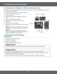
5. Exploded Views and Parts List<br />
5-3 Door Parts List<br />
D002<br />
(S.N.A : SERVICE NOT AVAILABLE)<br />
D037<br />
D003<br />
Level No. Code No. Description Specification Q’ty SA/SNA Remark<br />
1-1 D049 DE94-00256J ASSY DOOR M1618/1638,GE/WHT 1 SA -<br />
1-2 D007 DE61-00198A SPRING KEY M1877,HSWR D6,23 1/4 T0 .7 1 SA -<br />
1-2 D011 DE64-40006F DOOR-KEY POM(F20-02),-,-,12G,BLK,MW7897 1 SA -<br />
1-2 D006 DE64-40008B DOOR-C -,PP,CE745G,-,-,-,BLK,- 1 SA -<br />
1-2 D037 DE94-00253J ASSY DOOR-A M1618,M1638/XEG,XET,PURE-WHT 1 SA -<br />
1-3 D002 DE64-00091J DOOR-A M1618/XEG,XET,ABS,-,GE-WHT,-,- 1 SA -<br />
1-3 D003 DE67-20186A SCREEN-DOOR SAN,T2 .2,W354,L224,SMOG,3RD- 1 SA -<br />
1-2 D015 DE94-00124B ASSY DOOR SUB MW4593G,BLK,3RD-0 .7,-,- 1 SA -<br />
1-3 D005 DE01-00112A FILM-DOOR -,PET,-,L268,T0 .15,W150,NTR,-, 1 SA -<br />
1-3 D004 DE92-50133C ASSY DOOR-E MW4593G,-,BLK,3RD-0 .7,-,-,- 1 SA -<br />
D004<br />
35<br />
D006<br />
D005<br />
D011<br />
D049<br />
D007<br />
D015
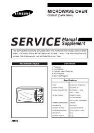
5. Exploded Views and Parts List<br />
5-4 Control Parts List<br />
C004<br />
(S.N.A : SERVICE NOT AVAILABLE)<br />
C009<br />
C007<br />
Level No. Code No. Description Specification Q’ty SA/SNA Remark<br />
1-1 C082 DE94-00979J ASSY-CONTROL BOX 230V50HZ,MW73VR/BWT,GE- 1 SNA -<br />
1-2 C004 DE34-00193G SWITCH MEMBRANE MW73VR/BWT,-,-,PET,-,230 1 SA -<br />
1-2 C070 DE61-00665A HOLDER-LED ALL-0 .8,PP,-,-,-,BLACK,LED-BA 1 SA -<br />
1-2 C006 DE61-70076A SPRING-BUTTON -,HSWR,PI0 .6,PI0 .6,-,-,-,- 1 SA -<br />
1-2 C007 DE66-20275B BUTTON-PUSH JES831WB,-,-,-,-,- 1 SA -<br />
1-2 C009 DE67-40179A WINDOW-DISPLAY SAN,T2 .0,-,-,SMOG,-,3RD-W 1 SA -<br />
1-2 C005 DE72-70201J CONTROL-PANEL JE735WZC,ABS(VE0855),-,-,- 1 SA -<br />
1-2 C003 RCS-SM3L-96 ASSY PCB PARTS MW73VR/BWT,SMPS,230V/50HZ 1 SA -<br />
C006<br />
36<br />
C070<br />
C005<br />
C082<br />
C003
5. Exploded Views and Parts List<br />
5-5 Standard Parts List<br />
(S.N.A : SERVICE NOT AVAILABLE)<br />
Level Code No. Description Specification Q’ty SA/<br />
SNA<br />
1-1 6002-001250 SCREW-TAPPING TH,+,2,M4,L8,Tin-Ni,SWRC18 1 SNA O/PANEL<br />
37<br />
Remark<br />
1-1 6006-001170 SCREW-ASSY TAPP WS,TH,+,M4,L10,ZPC(YEL) 3 SA PCB EARTH,P/C EARTH,NOISE FILTER EARTH<br />
1-1 6006-001176 SCREW-ASSY TAPT WT,PH,+,M4,L8,ZPC(YEL) 1 SNA BKT HVC & DIODE<br />
1-1 DE60-10051A SCREW-TAP PH -,-,MSWR,-,PH,M4,-,L6,-,- 1 SA DRIVE MOTOR<br />
1-1 DE60-10080A SCREW-WASHER -,-,-,-,M5,L12,-,2S,-,- 2 SA HVT,MGT<br />
1-1 DE60-10082I SCREW-A -,-,-,-,2S-4X10,FEFZY,-,-,-,- 7 SA C/BLOWER,B/PLATE,B/LATCH,AIR/<br />
COVER,PANEL<br />
1-1 DE60-30016A NUT-FLANGE M4,MSWR10,-,-,-,-,-,-,- 1 SA F-MOTOR<br />
1-2 6002-000630 SCREW-TAPPING PH,+,2S,M3,L8,ZPC(YEL),SWR 2 SA HOLDER PCB,PCB
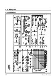
6. PCB Diagrams<br />
6-1 PCB Diagrams<br />
(This Document can not be used without Samsung’s authorization)<br />
6 CN01 A Terminal for Connecting with LVT A Terminal for Connecting with LVT and SMPS Power Supply<br />
7 CN02 A Terminal for Connecting with Relay A Terminal for Connecting with Relay and SMPS Power Supply<br />
8 CN03 A Terminal for Connecting with Connector A Terminal for Connecting with Connector and SMPS Power Supply<br />
9 CN04 A Terminal for Connecting with T/T LAMP A Terminal for Connecting with T/T Lamp and SMPS Power Supply<br />
10 CN05 A Terminal for Connecting with Humidity Sensor A Terminal for Connecting with Humidity Sensor and SMPS Power Supply<br />
Parts<br />
No .<br />
Part Name Function and Rule<br />
Number<br />
1 RY01 Main Relay Power Supply Relay<br />
2 RY02 Inrush Relay Inrush Electric Current Decrease Device<br />
3 RY03 Power Relay MWO Control Relay<br />
4 RY04 Grill Heater Relay MWO Grill Heater Control Relay<br />
5 RY05 T/T Relay T/T control Relay<br />
⑧<br />
⑦<br />
38<br />
③<br />
④<br />
①<br />
⑥<br />
⑤<br />
⑨<br />
⑩<br />
②
7. Wiring Diagrams<br />
7-1 Wiring Diagrams<br />
(This Document can not be used without Samsung’s authorization)<br />
NOTE<br />
1. INPUT : 230V<br />
2. DOOR : OPEN<br />
3. LAMP : ON<br />
<strong>4.</strong> : ASSY NOISE FILTER PATTERN<br />
5. : PCB PATTERN<br />
ASSY PCB BORD<br />
BRN BROWN<br />
RED RED<br />
BLU BLUE<br />
YEL YELLOW<br />
Y/G YELLOW/GREEN<br />
ORG ORANGE<br />
WHT WHITE<br />
BLK BLACK<br />
GRN GREEN<br />
MONITOR FUSE<br />
(250V 1.6A)<br />
GROUND<br />
ORG<br />
SYMBOL COLOR<br />
BLU<br />
GRN<br />
ORG<br />
DOOR SENSING<br />
SWITCH<br />
POWER RELAY<br />
(SECONDARY INTERLOCK)<br />
BLU<br />
BLK<br />
N<br />
39<br />
BLU<br />
MAIN RELAY<br />
WHT<br />
INRUSH RELAY<br />
P.T.C<br />
H.V.D<br />
0.1uF<br />
1mH<br />
FA F<br />
MAGNETRON<br />
Y/G<br />
2200pF<br />
POWER<br />
CORD<br />
230V~50Hz<br />
YEL<br />
H.V.C<br />
YEL<br />
BLK<br />
H.V.FUSE<br />
GRN<br />
BLK<br />
P.T.C<br />
500K<br />
2200pF<br />
BLK<br />
NC<br />
MONITOR<br />
S/W<br />
L<br />
S.M.P.S<br />
0V<br />
L F/M D/M<br />
21V<br />
230V<br />
COM NO<br />
BRN<br />
FUSE<br />
250V12A<br />
BRN<br />
WHT<br />
ORG<br />
BRN<br />
H.V.TRANS<br />
COM<br />
BRN<br />
BRN WHT<br />
BRN<br />
ASSY NOISE FILTER MGT/CAVITY TCO PRIMARY S/W
7. Wiring Diagrams<br />
7-1 Wiring Diagrams<br />
(This Document can not be used without Samsung’s authorization)<br />
HIGH VOLTAGE<br />
TRANSFORMER<br />
BLU<br />
RED<br />
BRN<br />
H.V.FUSE<br />
RED<br />
RED<br />
40<br />
RED<br />
HIGH VOLTAGE CAPACITOR<br />
FA F<br />
TO CHASSIS<br />
HIGH VOLTAGE<br />
DIODE<br />
MAGNETRON
41<br />
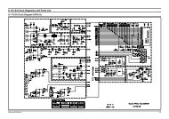
8. Schematic Diagrams<br />
8-1 Schematic Diagrams<br />
(This Document can not be used without Samsung’s authorization)
GSPN (Global Service Partner Network)<br />
Contry Web Site<br />
North America service .samsungportal .com<br />
Latin America latin .samsungportal .com<br />
CIS cis .samsungportal .com<br />
Europe europe .samsungportal .com<br />
China china .samsungportal .com<br />
Asia asia .samsungportal .com<br />
Mideast & Africa mea .samsungportal .com<br />
© Samsung Electronics Co ., Ltd . June . 2007<br />
Printed in Korea<br />
Code No . : DE68-04508A