c100r-5d/bwt
c100r-5d/bwt
c100r-5d/bwt

You also want an ePaper? Increase the reach of your titles
YUMPU automatically turns print PDFs into web optimized ePapers that Google loves.
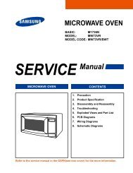
BASIC: C100R-5U/BWT<br />
MODEL: C100R-5D<br />
MODEL CODE: C100R-5D/BWT<br />
1. 1.0 cu.ft convection<br />
2. LED - Bar
• Contents<br />
1. Precaution . . . . . . . . . . . . . . . . . . . . . . . . . . . . . . . . . . . . . . . . . . . . . . . . . . . . . . . . . . . . . . . . . . . . . . . . . . . . . . . . . . . . . . . . . . . . 3<br />
1-1 Safety precautions . . . . . . . . . . . . . . . . . . . . . . . . . . . . . . . . . . . . . . . . . . . . . . . . . . . . . . . . . . . . . . . . . . . . . . . . . . . . . . . . . . . 4<br />
1-2 Special High Voltage Precautions . . . . . . . . . . . . . . . . . . . . . . . . . . . . . . . . . . . . . . . . . . . . . . . . . . . . . . . . . . . . . . . . . . . . . . . 5<br />
2. Specifications . . . . . . . . . . . . . . . . . . . . . . . . . . . . . . . . . . . . . . . . . . . . . . . . . . . . . . . . . . . . . . . . . . . . . . . . . . . . . . . . . . . . . . . . . 6<br />
2-1 Table of Specifications . . . . . . . . . . . . . . . . . . . . . . . . . . . . . . . . . . . . . . . . . . . . . . . . . . . . . . . . . . . . . . . . . . . . . . . . . . . . . . . . 6<br />
2-2 Accessory . . . . . . . . . . . . . . . . . . . . . . . . . . . . . . . . . . . . . . . . . . . . . . . . . . . . . . . . . . . . . . . . . . . . . . . . . . . . . . . . . . . . . . . . . 7<br />
3. Operating Instructions . . . . . . . . . . . . . . . . . . . . . . . . . . . . . . . . . . . . . . . . . . . . . . . . . . . . . . . . . . . . . . . . . . . . . . . . . . . . . . . . . . 8<br />
3-1 Control Panel . . . . . . . . . . . . . . . . . . . . . . . . . . . . . . . . . . . . . . . . . . . . . . . . . . . . . . . . . . . . . . . . . . . . . . . . . . . . . . . . . . . . . . . 8<br />
3-2 Features & External Views . . . . . . . . . . . . . . . . . . . . . . . . . . . . . . . . . . . . . . . . . . . . . . . . . . . . . . . . . . . . . . . . . . . . . . . . . . . . 9<br />
4. Disassembly and Reassembly . . . . . . . . . . . . . . . . . . . . . . . . . . . . . . . . . . . . . . . . . . . . . . . . . . . . . . . . . . . . . . . . . . . . . . . . . . . 10<br />
4-1 Replacement of Magnetron, Motor Assembly and Lamp . . . . . . . . . . . . . . . . . . . . . . . . . . . . . . . . . . . . . . . . . . . . . . . . . . . . 10<br />
4-2 Replacement of High Voltage Transformer . . . . . . . . . . . . . . . . . . . . . . . . . . . . . . . . . . . . . . . . . . . . . . . . . . . . . . . . . . . . . . . 10<br />
4-3 Replacement of Door Assembly . . . . . . . . . . . . . . . . . . . . . . . . . . . . . . . . . . . . . . . . . . . . . . . . . . . . . . . . . . . . . . . . . . . . . . . 11<br />
4-3-1 Removal of Door Assembly . . . . . . . . . . . . . . . . . . . . . . . . . . . . . . . . . . . . . . . . . . . . . . . . . . . . . . . . . . . . . . . . . . . . . . 11<br />
4-3-2 Removal of Door “C” . . . . . . . . . . . . . . . . . . . . . . . . . . . . . . . . . . . . . . . . . . . . . . . . . . . . . . . . . . . . . . . . . . . . . . . . . . . 11<br />
4-3-3 Removal of Door “E” . . . . . . . . . . . . . . . . . . . . . . . . . . . . . . . . . . . . . . . . . . . . . . . . . . . . . . . . . . . . . . . . . . . . . . . . . . . 11<br />
4-3-4 Removal of Key Door & Spring . . . . . . . . . . . . . . . . . . . . . . . . . . . . . . . . . . . . . . . . . . . . . . . . . . . . . . . . . . . . . . . . . . . 11<br />
4-3-5 Removal of Screen-Door & Deco-door . . . . . . . . . . . . . . . . . . . . . . . . . . . . . . . . . . . . . . . . . . . . . . . . . . . . . . . . . . . . . 11<br />
4-3-6 Reassembly Test . . . . . . . . . . . . . . . . . . . . . . . . . . . . . . . . . . . . . . . . . . . . . . . . . . . . . . . . . . . . . . . . . . . . . . . . . . . . . . 12<br />
4-4 Replacement of Fuse . . . . . . . . . . . . . . . . . . . . . . . . . . . . . . . . . . . . . . . . . . . . . . . . . . . . . . . . . . . . . . . . . . . . . . . . . . . . . . . 12<br />
4-5 Replacement of Drive Motor . . . . . . . . . . . . . . . . . . . . . . . . . . . . . . . . . . . . . . . . . . . . . . . . . . . . . . . . . . . . . . . . . . . . . . . . . . 12<br />
4-6 Replacement of Control Circuit Board . . . . . . . . . . . . . . . . . . . . . . . . . . . . . . . . . . . . . . . . . . . . . . . . . . . . . . . . . . . . . . . . . . . 13<br />
5. Alignment and Adjustments . . . . . . . . . . . . . . . . . . . . . . . . . . . . . . . . . . . . . . . . . . . . . . . . . . . . . . . . . . . . . . . . . . . . . . . . . . . . . 14<br />
5-1 High Voltage Transformer . . . . . . . . . . . . . . . . . . . . . . . . . . . . . . . . . . . . . . . . . . . . . . . . . . . . . . . . . . . . . . . . . . . . . . . . . . . . 14<br />
5-2 Low Voltage Transformer . . . . . . . . . . . . . . . . . . . . . . . . . . . . . . . . . . . . . . . . . . . . . . . . . . . . . . . . . . . . . . . . . . . . . . . . . . . . 14<br />
5-3 Magnetron . . . . . . . . . . . . . . . . . . . . . . . . . . . . . . . . . . . . . . . . . . . . . . . . . . . . . . . . . . . . . . . . . . . . . . . . . . . . . . . . . . . . . . . . 14<br />
5-4 High Voltage Capacitor . . . . . . . . . . . . . . . . . . . . . . . . . . . . . . . . . . . . . . . . . . . . . . . . . . . . . . . . . . . . . . . . . . . . . . . . . . . . . . 15<br />
5-5 High Voltage Diode . . . . . . . . . . . . . . . . . . . . . . . . . . . . . . . . . . . . . . . . . . . . . . . . . . . . . . . . . . . . . . . . . . . . . . . . . . . . . . . . . 15<br />
5-6 Main Relay and Power Control RelayA . . . . . . . . . . . . . . . . . . . . . . . . . . . . . . . . . . . . . . . . . . . . . . . . . . . . . . . . . . . . . . . . . . 15<br />
5-7 Adjustment of Primary Switch, Door Sensing Switch and Monitor Switch . . . . . . . . . . . . . . . . . . . . . . . . . . . . . . . . . . . . . . . . 15<br />
5-8 Output Power of Magnetron . . . . . . . . . . . . . . . . . . . . . . . . . . . . . . . . . . . . . . . . . . . . . . . . . . . . . . . . . . . . . . . . . . . . . . . . . . 16<br />
5-9 Procedure for Measurement of Microwave Energy Leakage . . . . . . . . . . . . . . . . . . . . . . . . . . . . . . . . . . . . . . . . . . . . . . . . . 17<br />
5-10 Check for Microwave Leakage . . . . . . . . . . . . . . . . . . . . . . . . . . . . . . . . . . . . . . . . . . . . . . . . . . . . . . . . . . . . . . . . . . . . . . . 17<br />
5-11 Note on Measurement . . . . . . . . . . . . . . . . . . . . . . . . . . . . . . . . . . . . . . . . . . . . . . . . . . . . . . . . . . . . . . . . . . . . . . . . . . . . . . 17<br />
5-12 Leakage Measuring Procedure . . . . . . . . . . . . . . . . . . . . . . . . . . . . . . . . . . . . . . . . . . . . . . . . . . . . . . . . . . . . . . . . . . . . . . . 17<br />
5-12-1 Record keeping and notification after measurement . . . . . . . . . . . . . . . . . . . . . . . . . . . . . . . . . . . . . . . . . . . . . . . . . . 17<br />
5-12-2 At least once a year have the microwave energy survey meter checked for accuracy by its manufacturer. . . . . . . . . 17<br />
6. Troubleshooting . . . . . . . . . . . . . . . . . . . . . . . . . . . . . . . . . . . . . . . . . . . . . . . . . . . . . . . . . . . . . . . . . . . . . . . . . . . . . . . . . . . . . . 18<br />
6-1 Electrical Malfunction . . . . . . . . . . . . . . . . . . . . . . . . . . . . . . . . . . . . . . . . . . . . . . . . . . . . . . . . . . . . . . . . . . . . . . . . . . . . . . . 18<br />
6-2 Unsatisfactory Cooking . . . . . . . . . . . . . . . . . . . . . . . . . . . . . . . . . . . . . . . . . . . . . . . . . . . . . . . . . . . . . . . . . . . . . . . . . . . . . . 22<br />
6-3 Part Check List . . . . . . . . . . . . . . . . . . . . . . . . . . . . . . . . . . . . . . . . . . . . . . . . . . . . . . . . . . . . . . . . . . . . . . . . . . . . . . . . . . . . 22<br />
7. Exploded Views and Parts List . . . . . . . . . . . . . . . . . . . . . . . . . . . . . . . . . . . . . . . . . . . . . . . . . . . . . . . . . . . . . . . . . . . . . . . . . . 23<br />
7-1 Exploded Views . . . . . . . . . . . . . . . . . . . . . . . . . . . . . . . . . . . . . . . . . . . . . . . . . . . . . . . . . . . . . . . . . . . . . . . . . . . . . . . . . . . . 23<br />
7-2 Main Parts List . . . . . . . . . . . . . . . . . . . . . . . . . . . . . . . . . . . . . . . . . . . . . . . . . . . . . . . . . . . . . . . . . . . . . . . . . . . . . . . . . . . . . 24<br />
7-3 Door Parts List . . . . . . . . . . . . . . . . . . . . . . . . . . . . . . . . . . . . . . . . . . . . . . . . . . . . . . . . . . . . . . . . . . . . . . . . . . . . . . . . . . . . . 26<br />
7-4 Control Parts List . . . . . . . . . . . . . . . . . . . . . . . . . . . . . . . . . . . . . . . . . . . . . . . . . . . . . . . . . . . . . . . . . . . . . . . . . . . . . . . . . . . 27<br />
7-5 Casing Parts List . . . . . . . . . . . . . . . . . . . . . . . . . . . . . . . . . . . . . . . . . . . . . . . . . . . . . . . . . . . . . . . . . . . . . . . . . . . . . . . . . . . 28<br />
7-6 Standard Parts List . . . . . . . . . . . . . . . . . . . . . . . . . . . . . . . . . . . . . . . . . . . . . . . . . . . . . . . . . . . . . . . . . . . . . . . . . . . . . . . . . 29<br />
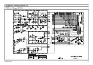
8. Schematic Diagrams . . . . . . . . . . . . . . . . . . . . . . . . . . . . . . . . . . . . . . . . . . . . . . . . . . . . . . . . . . . . . . . . . . . . . . . . . . . . . . . . . . . 30<br />
8-1. Schematic Diagrams . . . . . . . . . . . . . . . . . . . . . . . . . . . . . . . . . . . . . . . . . . . . . . . . . . . . . . . . . . . . . . . . . . . . . . . . . . . . . . . 30<br />
9. Electrical Parts List . . . . . . . . . . . . . . . . . . . . . . . . . . . . . . . . . . . . . . . . . . . . . . . . . . . . . . . . . . . . . . . . . . . . . . . . . . . . . . . . . . . . 31<br />
9-1. Electrical Parts List . . . . . . . . . . . . . . . . . . . . . . . . . . . . . . . . . . . . . . . . . . . . . . . . . . . . . . . . . . . . . . . . . . . . . . . . . . . . . . . . . 31<br />
10. Wiring Diagrams . . . . . . . . . . . . . . . . . . . . . . . . . . . . . . . . . . . . . . . . . . . . . . . . . . . . . . . . . . . . . . . . . . . . . . . . . . . . . . . . . . . . . 33<br />
10-1 Wiring Diagrams . . . . . . . . . . . . . . . . . . . . . . . . . . . . . . . . . . . . . . . . . . . . . . . . . . . . . . . . . . . . . . . . . . . . . . . . . . . . . . . . . . 33<br />
11. Reference . . . . . . . . . . . . . . . . . . . . . . . . . . . . . . . . . . . . . . . . . . . . . . . . . . . . . . . . . . . . . . . . . . . . . . . . . . . . . . . . . . . . . . . . . . . 34<br />
11-1 Model name standard . . . . . . . . . . . . . . . . . . . . . . . . . . . . . . . . . . . . . . . . . . . . . . . . . . . . . . . . . . . . . . . . . . . . . . . . . . . . . . 34<br />
11-2 Customer inquiry cases and countermeasures . . . . . . . . . . . . . . . . . . . . . . . . . . . . . . . . . . . . . . . . . . . . . . . . . . . . . . . . . . . 35<br />
2
1. Precaution<br />
3
1. Precaution<br />
Follow these special safety precautions. Although the microwave oven is completely safe during ordinary use,<br />
repair work can be extremely hazardous due to possible exposure to microwave radiation, as well as potentially<br />
lethal high voltages and currents.<br />
1-1 Safety precautions ( )<br />
1. All repairs should be done in accordance with the<br />
procedures described in this manual. This product<br />
complies with Federal Performance Standard 21<br />
CFR<br />
2. Microwave emission check should be performed to<br />
prior to servicing if the oven is operative.<br />
3. If the oven operates with the door open :Instruct<br />
the user not to operate the oven and contact<br />
the manufacturer and the center for devices and<br />
radiological health immediately.<br />
4. Notify the Central Service Center if the microwave<br />
leakage exceeds 5 mW/cm2.<br />
5. Check all grounds.<br />
6. Do not power the MWO from a “2-prong” AC cord.<br />
Be sure that all of the built-in protective devices are<br />
replaced. Restore any missing protective shields.<br />
7. When reinstalling the chassis and its assemblies,<br />
be sure to restore all protective devices, including:<br />
nonmetallic control knobs and compartment covers.<br />
8. Make sure that there are no cabinet openings<br />
through which people --particularly children--might<br />
insert objects and contact dangerous voltages.<br />
Examples: Lamp hole,ventilation slots.<br />
9. Inform the manufacturer of any oven foundto have<br />
emission in excess of 5 mW/cm2 ,Make repairs to<br />
bring the unit into compliance at no cost to owner<br />
and try to determine cause. Instruct owner not to use<br />
oven until it has been brought into compliance.<br />
CENTRAL SERVICE CENTER<br />
10. Service technicians should remove their watches<br />
while repairing an MWO.<br />
11. To avoid any possible radiation hazard,replace parts<br />
in accordance with the wiring diagram. Also, use<br />
only the exact replacements for the following parts:<br />
Primary and secondary interlock switches, interlock<br />
monitor switch.<br />
12. If the fuse is blown by the Interlock Monitor Switch:<br />
Replace all of the following at the same time:<br />
Primary, door sensing switch and power relay, as<br />
well as the Interlock Monitor Switch. The correct<br />
adjustment of these switches is described elsewhere<br />
in this manual. Make sure that the fuse has the<br />
correct rating for the particular model being repaired.<br />
4<br />
13. Design Alteration Warning: Use exact replacement<br />
parts only, i.e.,only those that are specified in<br />
thedrawings and parts lists of this manual. This<br />
is especially important for the Interlock switches,<br />
described above. Never alter or add to the<br />
mechanical or electrical design of the MWO.<br />
Any design changes or additions will void the<br />
manufacturer’s warranty. Always unplug the unit’s<br />
AC power cord from the AC power source before<br />
attempting to remove or reinstall any component or<br />
assembly.<br />
14. Never defeat any of the B+ voltage interlocks. Do not<br />
apply AC power to the unit (or any of its assemblies)<br />
unless all solid-state heat sinks are correctly<br />
installed.<br />
15. Some semiconductor (“solid state”) devices<br />
are easily damaged by static electricity. Such<br />
components are called Electrostatically Sensitive<br />
Devices (ESDs). Examples include integrated<br />
circuits and field-effect transistors. Immediately<br />
before handling any semiconductor components or<br />
assemblies, drain the electrostatic charge from your<br />
body by touching a known earth ground.<br />
16. Always connect a test instrument’s ground lead to<br />
the instrument chassis ground before connecting the<br />
positive lead; always remove the instrument’s ground<br />
lead last.<br />
17. When checking the continuity of the witches or<br />
transformer, always make sure that the power is<br />
OFF, and one of the lead wires is disconnected.<br />
18. Components that are critical for safety are indicated<br />
in the circuit diagram by shading, or .<br />
19. Use replacement components that have the same<br />
ratings, especially for flame resistance and dielectric<br />
strength specifications. A replacement part that does<br />
not have the same safety characteristics as the<br />
original might create shock, fire or other hazards.<br />
NOTE : Connect the oven to a 20A. When<br />
connecting the oven to a 15A,make sure that circuit<br />
breaker can operate.
1. Precaution<br />
1-2 Special High Voltage Precautions<br />
1. High Voltage Warning Do not attempt to measure any<br />
of the high voltages --this includes the filament voltage<br />
of the magnetron. High voltage is present during any<br />
cook cycle. Before touching any components or wiring,<br />
always unplug the oven and discharge the high voltage<br />
capacitor (See Figure 1-1)<br />
2. The high-voltage capacitor remains charged about<br />
30 seconds after disconnection. Short the negative<br />
terminal of the high-voltage capacitor to to the oven<br />
chassis. (Use a screwdriver.)<br />
3. High voltage is maintained within specified limits<br />
by close-tolerance, safety-related components and<br />
adjustments. If the high voltage exceeds the specified<br />
limits, check each of the special components.<br />
5<br />
H. V. Capacitor<br />
Short<br />
Touch chassis ground first then short to the<br />
high voltage capacitor terminal by using<br />
screwdriver or jumper wire.<br />
There exists HIGH VOLTAGE ELECTRICITY with high current capabilities in the circuits of the HIGH<br />
VOLTAGE TRANSFORMER secondary and filament terminals. It is extremely dangerous to work on or near<br />
these circuits with the oven energized.<br />
DO NOT measure the voltage in the high voltage circuit including filament voltage of magnetron.<br />
Never touch any circuit wiring with your hand nor<br />
with uninsulated tool during operation.<br />
Servicemen should remove their watches<br />
whenever working close to or replacing the<br />
magnetron.
2. Specifications<br />
2-1 Table of Specifications<br />
Items Sub Items<br />
6<br />
Model<br />
C100R-5D C100R-5U<br />
Power source 230 V ~ 50 Hz AC 230 V ~ 50 Hz AC<br />
Power<br />
comsumption<br />
Maximum Power 3100 W 3100 W<br />
Microwave 1400 W 1400 W<br />
Grill 1300 W 1300 W<br />
Convection 1700 W 1700 W<br />
Output Power 100 W / 900 W 100 W / 900 W<br />
Operating Frequency 2450 MHz 2450 MHz<br />
Dimension (W x D<br />
x H )<br />
Outside 517 x 511 x 310 mm 517 x 516 x 310 mm<br />
Oven cavity 336 x 346 x 222 mm 352 x 348 x 235 mm<br />
Volume 1.0 CU. FT 1.0 CU. FT<br />
Weight<br />
Shipping 24.5 Kg approx 22.5 Kg approx<br />
Net 22.5 Kg approx 19 Kg approx
2. Specifications<br />
2-2 Accessory<br />
Item Description Code No. Q’ty<br />
Coupler DE67-00182A 1<br />
ASSY-GUIDE ROLLER DE97-00222A 1<br />
TRAY-COOKING DE74-20015G 1<br />
ASSY-WIRE RACK DE97-00216E 1<br />
ASSY-WIRE RACK DE97-00136B 1<br />
7
3. Operating Instructions<br />
3-1 Control Panel<br />
1<br />
2<br />
3<br />
4<br />
5<br />
6<br />
7<br />
8<br />
9<br />
1. Display<br />
2. Auto defrost feature selection<br />
3. Standing time setting<br />
4. Memory cook feature selection<br />
5. Time setting weight selection and recipe selection<br />
6. Combined mode selection (microwave + grill)<br />
7. Grill mode selection<br />
8. preheat mode selection<br />
9. Stop / cabcel button<br />
8<br />
10<br />
11<br />
12<br />
13<br />
14<br />
15<br />
16<br />
10. Clock setting<br />
11. Auto reheat & Cook feature selection<br />
12. Cooking time adjustment<br />
13. Microwave / Power level mode selection<br />
14. Convection mode / Temperature selection<br />
15. Combined mode selection<br />
(microwave + convection)<br />
16. Start / cooking time adjustment button
3. Operating Instructions<br />
3-2 Features & External Views<br />
Door<br />
Door Latches<br />
336mm<br />
517mm<br />
Ventilation Holes Light Safety Interlock Holes<br />
Glass Plate<br />
Grill Rack<br />
9<br />
<br />
Guide Roller<br />
310mm<br />
Coupler<br />
346mm<br />
511mm<br />
Control Pane
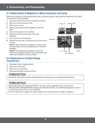
4. Disassembly and Reassembly<br />
4-1 Replacement of Magnetron, Motor Assembly and Lamp<br />
Remove the magnetron including the shield case, permanent magnet, choke coils and capacitors (all of which<br />
are contained in one assembly).<br />
1. Disconnect all lead wires from the magnetron and lamp.<br />
2. Remove a screw securing air cover.<br />
3. Remove the air cover.<br />
4. Remove screws securing the magnetron to the wave<br />
guide.<br />
5. Take out the magnetron very carefully.<br />
6. Remove tow from the back panel of fan motor<br />
assembly.<br />
7. Take out the fan motor assembly.<br />
8. Remove the oven lamp by rotating to pull out from hole of<br />
air cover.<br />
NOTE1: When removing the magnetron, make sure that<br />
its antenna does not hit any adjacent parts, or it may be<br />
damaged.<br />
NOTE2: When replacing the magnetron, be sure to<br />
remount the magnetron gasket in the correct position and<br />
make sure the gasket is in good condition.<br />
4-2 Replacement of High Voltage<br />
Transformer<br />
1. Discharge the high voltage capacitor.<br />
2. Disconnect all the leads.<br />
3. Remove the mounting bolts.<br />
4. Reconnect the leads correctly and firmly.<br />
Servicemen should remove their watches whenever working close to or replacing the magnetron.<br />
There exists HIGH VOLTAGE ELECTRICITY with high current capabilities in the circuits of the<br />
HIGHVOLTAGE TRANSFORMER secondary and filament terminals. It is extremely dangerous to work on<br />
or near these circuits with the oven energized.<br />
DO NOT measure the voltage in the high voltage circuit including filament voltage of magnetron.<br />
10<br />
Magnetron<br />
Cover Air<br />
Thermo S/W<br />
H. V. Trans<br />
H.V Capacitor<br />
Fan Motor<br />
Screw
Screws<br />
Upper Hinge<br />
Screws<br />
4. Disassembly and Reassembly<br />
Low Hinge<br />
4-3 Replacement of Door Assembly<br />
4-3-1 Removal of Door Assembly<br />
Securing the upper hinge and lower hinge.<br />
The remove door assembly<br />
Screws<br />
Low Hinge<br />
Screws<br />
Low Hinge<br />
Door Screws "A"<br />
Upper Hinge<br />
4-3-3 Removal of Door “E”<br />
Following the procedure as shown in the figure,<br />
insert and bend a thin metal plate between Door “E”<br />
and Door “A” until you hear the ‘tick’ sound.<br />
• Insertion depth of the thin metal plate should be<br />
Door "C"<br />
Door "A"<br />
4-3-5 Removal of Screen-Door & Decodoor<br />
1. Remove Door “E” from Door “A”<br />
2. Remove Door-screen Door “B” "E"<br />
Deco-Door<br />
Door "C"<br />
Door "E"<br />
Door "C"<br />
Door "E"<br />
Door "E"<br />
Key Door<br />
Screws<br />
Spring<br />
Screws<br />
Door "A"<br />
Upper Hinge<br />
<br />
<br />
4-3-2 Removal of Door “C”<br />
Insert flat screwdriver into the gap between Door “A”<br />
and Door “C” to remove Door “C” Be caful when handing<br />
Door “C” because it is fragile<br />
4-3-4 Removal of Key Door & Spring<br />
Remove pin hinge grom Door “E” Datach spring from<br />
Door “E” and key door<br />
Deco-Door<br />
11<br />
Low Hinge<br />
Deco-Door<br />
<br />
Key Door<br />
Door "E"<br />
Key Door<br />
Deco-Door<br />
Door "C"<br />
Door "E"<br />
Key Door<br />
Door "E"<br />
Spring<br />
Screws<br />
Spring Door "A"<br />
Spring<br />
<br />
Deco-Door
4. Disassembly and Reassembly<br />
4-3 Replacement of Door Assembly (Continued)<br />
4-3-6 Reassembly Test<br />
After replacement of the defective component parts of the door, reassemble it and follow the<br />
instructions below for proper installation and adjustment so as to prevent an excessive microwave<br />
leakage.<br />
1. When mounting the door to the oven, be sure to adjust the door parallel to the bottom line of the oven face plate<br />
by moving the upper hinge and lower hinge in the direction necessary for proper alignment.<br />
2. Adjust so that the door has no play between the inner door surface and oven front surface. If the door assembly is<br />
not mounted properly, microwave energy may leak from the space between the door and oven.<br />
3. Do the microwave leakage test.<br />
4-4 Replacement of Fuse<br />
1. Disconnect the oven from the power source.<br />
2. When 12A fuse blows out by the operation of interlock monitor switch failure, replace the primary interlock switch,<br />
door sensing switch, monitor switch and power relay.<br />
3. When the above three switches operate properly, check if any other part such as the control circuit board, blower<br />
motor or high voltage transformer is defective.<br />
4-5 Replacement of Drive Motor<br />
1. Take out the glass tray, guide roller from oven cavity,<br />
disconnect power.<br />
2. Remove turn table motor cover from case bottom.<br />
CAUTION : Remove sharp edge after cover<br />
removal.<br />
3. Disconnect leads from motor.<br />
4. Remove the screws securing motor to bottom of<br />
over cavity and lift out the motor.<br />
5. When replacing the motor, be sure to remount it in<br />
the correct position.<br />
NOTE : The shaft of motor should fit tip coupler.<br />
6. Screw the motor to bottom of oven cavity.<br />
7. Connect leads to the drive motor.<br />
8. Screw the drive motor cover to the base plate with a<br />
screw driver.<br />
NOTE : Bring the spare screw from service center.<br />
COVER FIXING SCREW : MATCHINE SCREW(6006-001170)<br />
12<br />
Screw<br />
Drive Motor Cover<br />
Drive Motor<br />
Base Plate
4. Disassembly and Reassembly<br />
4-6 Replacement of Control Circuit Board<br />
1. Be sure to dislyarge any static electricity from your body, and<br />
avoid touching the “touch control” circuitry<br />
2. Disconnect the connectors from the control circuit board.<br />
3. Remove screws securing the control box assembly.<br />
4. Lift up the control circuit board from right side and remove<br />
the hooks holding the control circuit board to box assembly<br />
SCREWS<br />
13
5. Alignment and Adjustments<br />
1. High voltage is present at the high voltage terminals during any cook cycle.<br />
2. It is neither necessary nor advisable to attempt measurement of the high voltage.<br />
3. Before touching any oven components or wiring, always unplug the oven from its power source and<br />
discharge the high voltage capacitor.<br />
5-1 High Voltage Transformer<br />
1. Remove connectors from the transformer terminals and<br />
check continuity.<br />
2. Normal resistance readings are as follows:<br />
Secondary Approx. 162Ω<br />
Filament Approx. 0Ω<br />
Primary Approx. 2.14Ω<br />
(Room temperature = 20°C)<br />
5-2 Low Voltage Transformer<br />
1. The low voltage transformer is located on the control circuit board.<br />
2. Remove the low voltage transformer from the PCB Ass’y and check continuity.<br />
3. Normal resistor reading is shown in the table.<br />
Terminals Resistance<br />
1~2(Input) 290Ω.<br />
3~4(Output) 4.0Ω.<br />
5~6(Output) 1.0Ω.<br />
5-3 Magnetron<br />
1. Continuity checks can indicate only an open filament or<br />
a shorted magnetron. To diagnose an open filament or<br />
shorted magnetron.<br />
2. Isolate the magnetron from the circuit by disconnecting its<br />
leads.<br />
3. A continuity check across the magnetron filament terminals<br />
should indicate one ohm or less.<br />
4. A continuity check between each filament terminal and<br />
magnetron case should read open.<br />
14<br />
Filament Terminals<br />
Primary<br />
Terminals<br />
Gasket Plate<br />
Cooling Fins<br />
Magnetron Antenna<br />
Secondary<br />
Terminal
5. Alignment and Adjustments<br />
5-4 High Voltage Capacitor<br />
1. Check continuity of the capacitor with the meter set at the highest resistance scale.<br />
2. Once the capacitor is charged, a normal capacitor shows continuity for a short time, and then indicates 9MΩ.<br />
3. A shorted capacitor will show continuous continuity.<br />
4. An open capacitor will show constant 9MΩ.<br />
5. Resistance between each terminal and chassis should read infinite.<br />
5-5 High Voltage Diode<br />
1. Isolate the diode from the circuit by disconnecting its leads.<br />
2. With the ohm-meter set at the highest resistance scale, measure across the diode terminals. Reverse the meter<br />
leads and read the resistance. A meter with 6V, 9V or higher voltage batteries should be used to check the front-to<br />
back resistance of the diode (otherwise an infinite resistance may be read in both directions). The resistance of a<br />
normal diode will be infinite in one direction and several hundred KΩ in the other direction.<br />
5-6 Main Relay and Power Control RelayA<br />
1. The relays are located on the PCB Ass’y. Isolate them from the main circuit by disconnecting the leads.<br />
2. Operate the microwave oven with a water load in the oven. Set the power level set to high.<br />
3. Check continuity between terminals of the relays after the start pad is pressed.<br />
5-7 Adjustment of Primary Switch, Door Sensing Switch and Monitor Switch<br />
For continued protection against radiation hazard, replace parts in accordance with the wiring diagram<br />
and be sure to use the correct part number for the following switches: Primary and secondary interlock<br />
switches, and the interlock monitor switch (replace all together). Then follow the adjustment procedures<br />
below. After repair and adjustment, be sure to check the continuity of all interlock switches and the interlock<br />
monitor switch.<br />
1. When mounting Primary switch and Interlock Monitor<br />
switch to Latch Body, consult the figure.<br />
2. No specific adjustment during installation of Primary switch<br />
and Monitor switch to the latch body is necessary.<br />
3. When mounting the Latch Body to the oven assembly,<br />
adjust the Latch Body by moving it so that the oven door<br />
will not have any play in it. Check for play in the door by<br />
pulling the door assembly. Make sure that the latch keys<br />
move smoothly after adjustment is completed. Completely<br />
tighten the screws holding the Latch Body to the oven<br />
assembly.<br />
4. Reconnect to Monitor switch and check the continuity of<br />
the monitor circuit and all latch switches again by following<br />
the components test procedures.<br />
5. Confirm that the gap between the switch housing and<br />
the switch actuator is no more than 0.5mm when door is<br />
closed.<br />
6. Interlock Switch Replacement - When replacing faulty<br />
switches, be sure switch mounting tabs are not bent,<br />
broken or otherwise deficient in their ability to secure the<br />
switches in place.<br />
15<br />
Body Latch<br />
Primary Interlock switch<br />
Monitor switch(COM-NC)<br />
Door Sensing S/W<br />
(Secondary interlock)<br />
Primary Interlock Switch<br />
Interlock Monitor<br />
Switch<br />
Lever Door(B)<br />
Door Sensing<br />
Switch<br />
Door Open Door Closed<br />
∞<br />
0<br />
0<br />
∞<br />
∞<br />
0<br />
∞<br />
0
5. Alignment and Adjustments<br />
5-8 Output Power of Magnetron<br />
MICROWAVE RADIATION<br />
PERSONNEL SHOULD NOT ALLOW EXPOSURE TO MICROWAVE RADIATION FROM MICROWAVE<br />
GENERATOR OR OTHER PARTS CONDUCTING MICROWAVE ENERGY.<br />
The output power of the magnetron can be measured by performing a water temperature rise test.<br />
Equipment needed :<br />
• Two 1-liter cylindrical borosilicate glass vessel (Outside diameter 190 mm)<br />
• One glass thermometer with mercury column<br />
NOTE: Check line voltage under load. Low voltage will lower the magnetron output. Make all temperature and<br />
time tests with accurate equipment.<br />
1. Fill the one liter glass vessel with water.<br />
2. Stir water in glass vessel with thermometer, and record glass vessel’s temperature (“T1”, 10±1°C).<br />
3. After moving the water into another glass vessel, place it in the center of the cooking tray. Set the oven to high<br />
power and operate for 50 seconds exactly. (3 seconds included as a holding time of magnetron oscillation:)<br />
4. When heating is finished, stir the water again with the thermometer and measure the temperature (“T2”).<br />
5. Subtract T1 from T2. This will give you the water temperature rise. (∆T)<br />
6. The output power is obtained by the following formula;<br />
Output Power = 4.187 x 1000 x ∆T+0.55xMcx(T2 -T1) 50 : Heating Time (sec)<br />
47<br />
47 : Counting Time (sec)<br />
4.187 : Coefficient for Water<br />
1000 : Water (cc)<br />
∆T : Temperature Rise (T2-T1)<br />
To : Room Temperature<br />
Mc : Cylindrical borosilicate glass weight<br />
7. Normal temperature rise for this model is 9°C to 11°C at ‘HIGH’.<br />
NOTE 1: Variations or errors in the test procedure will cause a variance in the temperature rise. Additional power<br />
test should be made if temperature rise is marginal.<br />
NOTE 2: Output power in watts is computed by multiplying the temperature rise (step 5) by a factor of 91 times the<br />
of centigrade temperature.<br />
16
5. Alignment and Adjustments<br />
5-9 Procedure for Measurement of Microwave Energy Leakage<br />
1. Pour 275±15cc of 20±5°C(68±9°F) water in a beaker which is graduated to<br />
600cc, and place the beaker in the center of the oven.<br />
2. Start to operate the oven and measure the leakage by using a microwave<br />
energy survey meter.<br />
3. Set survey meter with dual ranges to 2,450MHz.<br />
4. When measuring the leakage, always use the 2 inch spacer cone with the<br />
probe. Hold the probe perpendicular to the cabinet door. Place the spacer<br />
cone of the probe on the door and/or cabinet door seam and move along<br />
the seam, the door viewing window and the exhaust openings moving the<br />
probe in a clockwise direction at a rate of 1 inch/sec. If the leakage testing of the cabinet door seam is taken near<br />
a corner of the door, keep the probe perpendicular to the areas making sure that the probe end at the base of the<br />
cone does not get closer than 5cm to any metal. If it gets closer than 5cm, erroneous readings may result.<br />
5. Measured leakage must be less than 4mW/cm2 , after repair or adjustment.<br />
Maximum allowable leakage is 5mW/cm2 .<br />
4mW/cm2 is used to allow for measurement and meter accuracy<br />
5-10 Check for Microwave Leakage<br />
1. Remove the outer panel.<br />
2. Pour 275±15cc of 20±5°C(68±9°F) water in a beaker which is graduated to 600cc,<br />
and place the beaker in the center of the oven.<br />
3. Start the oven at the highest power level.<br />
4. Set survey meter dual ranges to 2,450MHz.<br />
5. Using the survey meter and spacer cone as described above, measure near the<br />
opening of magnetron, the surface of the air guide and the surface of the wave<br />
guide as shown in the following photo.( but avoid the high voltage components.)<br />
The reading should be less than 4mW/cm2 .<br />
5-11 Note on Measurement<br />
1. Do not exceed the limited scale.<br />
2. The test probe must be held on the grip of the handle, otherwise a false reading may result when the operator’s<br />
hand is between the handle and the probe.<br />
3. When high leakage is suspected, do not move the probe horizontally along the oven surface; this may cause<br />
damage to the probe.<br />
4. Follow the recommendation of the manufacturer of the microwave energy survey meter.<br />
5-12 Leakage Measuring Procedure<br />
5-12-1 Record keeping and notification after measurement<br />
1) After adjustment and repair of a radiation preventing device, make a repair record for the measured values, and<br />
keep the data.<br />
2) If the radiation leakage is more than 4mW/cm2 after determining that all parts are in good condition, functioning<br />
properly and the identical parts are replaced as listed in this manual notify that fact to ;<br />
CENTRAL SERVICE CENTER<br />
5-12-2 At least once a year have the microwave energy survey meter checked for<br />
accuracy by its manufacturer.<br />
17
6. Troubleshooting<br />
WARNING FOR HIGH VOLTAGE<br />
4000 VOLTS EXIST AT THE HIGH VOLTAGE AREA. DO NOT OPERATE THE OVEN WITH CABINET PARTS<br />
REMOVED. DO NOT REMOVE THE CABINET PARTS IF THE POWER SUPPLY CORD IS PLUGGED IN<br />
THE WALL OUTLET. UNPLUG THE POWER CORD BEFORE SERVICING.<br />
6-1 Electrical Malfunction<br />
Parts Cause Diagnosis Remedy<br />
Fuse blows<br />
out when<br />
door is<br />
opened.<br />
Fuse is<br />
Open<br />
Oven lamp<br />
does not<br />
light.<br />
Fan does<br />
not operate.<br />
Defective primary<br />
interlock switch<br />
are winding.<br />
Defective in terlock<br />
monitor switch<br />
Layer short of the<br />
secondary coil of<br />
H. V. Transformer<br />
Check continuity of the primary switch<br />
terminals with wire removed using a<br />
multimeter. If there is continuity inter<br />
between switch terminals when door is<br />
opened,the switch is defective.<br />
Check continuity of the monitor switch<br />
terminals with wire removed by using a<br />
multimeter. If there is continuity between<br />
switch terminals the door is closed, the<br />
switch is defective.<br />
The fuse will not blow right away, but if it<br />
blows in a few seconds, then there is a<br />
layer short If the fuse blows with H. V. Trans<br />
secondary open, the transformer may be<br />
faulty.<br />
18<br />
Replace the primary<br />
interlock switch<br />
Replace the interlock<br />
monitor switch<br />
Replace<br />
H.V.Transformer<br />
1) Fuse blown out Check fuse. Replace the fuse.<br />
2) Poor contact of<br />
power cord.<br />
3) Defective lamp<br />
4) Defective timer<br />
contacts<br />
5) Thermal cutout<br />
S/W open<br />
1) Defective fan<br />
motor.<br />
2) Defective con<br />
tacts of timer<br />
Check continuity of power supply cord. Also<br />
check whether the power cord is securely<br />
wired.<br />
The fan motor rotates, but lamp does not<br />
light.<br />
Check the terminals of timer for continuity,<br />
turning the timer knob ON and OFF<br />
repeatedly.<br />
In this case the oven lamp and fan do not<br />
turn on<br />
If 230V is found at motor terminals, the<br />
motor should be replaced.<br />
The oven lamp does not light and fan motor<br />
does not operate.<br />
NOTE: Interlock monitor switch must be replaced when the fuse is blown out.<br />
Adjust or replace the<br />
power supply cord<br />
Replace the lamp.<br />
Replace the timer.<br />
Replace the thermal<br />
cutout S/W<br />
Replace the motor.<br />
Replace the timer.
6. Troubleshooting<br />
part Cause Diagnosis Remedy<br />
Microwave<br />
turns off during<br />
cooking cycle.<br />
properly shock<br />
is felt.<br />
Door doe<br />
not operate<br />
properly<br />
Cooking tray<br />
does not<br />
rotate.<br />
Magnetron<br />
thermal cutout<br />
switch OFF<br />
1) Too small a load<br />
2) Defective<br />
magnetron thermal<br />
cutout S/W<br />
Incomplete grounding<br />
1) Broken door<br />
hinges<br />
2) Missing or loose<br />
screw<br />
1) Defective drive<br />
motor<br />
1) Blocking of the<br />
ventilatior<br />
2) Defective fan<br />
motor<br />
3) Too small a load or<br />
no load<br />
If a small amount of food is heated for a<br />
long time, period of microwave may turn<br />
off during operation.<br />
Check to see if the magnetron<br />
thermal cutout switch is activated at a<br />
temperature higher than 150 ºC.<br />
Make sure that qrounding of the power<br />
supply cord has been done properly.<br />
Remove the cabinet for inspection.<br />
Check the door hinge.<br />
Check if the screws are secured well to<br />
the door hinge.<br />
Check to see if 21V exists at the motor<br />
terminals.If so, motor will be defective.<br />
Check if the air inlet or outlet ventilation<br />
is blocked by the wall or other objects.<br />
If the fan motor does not operate with<br />
230V applied to the terminal, the motor<br />
may be faulty.<br />
If a small amount of food is heated<br />
repeatedly over a long period of time,<br />
microwave turns off during operation.<br />
19<br />
To increase the oven<br />
water into water into the<br />
oven.<br />
Replace thermal cutout<br />
switch.<br />
Rewire.<br />
Replace door hinges.<br />
Fasten or tighten.<br />
Replace drive motor.<br />
Keep a distance of<br />
100mm from the wall or<br />
the objects.<br />
Replace fan motor.<br />
To increase the oven<br />
load, place a glass of<br />
water into the oven.
6. Troubleshooting<br />
Oven does not operate.<br />
Is Fuse OK?<br />
YES<br />
Is the<br />
magnetron<br />
temperature switch<br />
normal?<br />
YES<br />
Is L.V.T normal?<br />
YES<br />
Is the IC01<br />
output of PCB<br />
normal?<br />
YES<br />
Checking high voltagecircuits<br />
NO Is Primary<br />
interlock switch<br />
normal?<br />
NO<br />
NO<br />
NO<br />
NO<br />
Caution<br />
1.Be careful of high voltage circuits.<br />
2. Discharge high voltage capacitor.<br />
YES<br />
Is Power Relay<br />
normal?<br />
Replace switch<br />
Replace L.V.T.<br />
Replace PCB.<br />
Is high voltage<br />
diode normal?<br />
YES<br />
Is high voltage<br />
capacitor normal?<br />
YES<br />
Is magnetron<br />
normal?<br />
20<br />
NO<br />
NO<br />
NO<br />
NO<br />
*Inspection method<br />
Make sure to inspect the power<br />
relay after replacing primary<br />
interlock switch, secondary interlock<br />
switch and door sensing switch.<br />
Primary interlock switch<br />
Secondary interlock switch<br />
Door sensing switch<br />
*Latch switch assembly<br />
Replace Relay<br />
Check a fan motor after replacing switch<br />
Check PCB after replacing L.V.T.<br />
Power Point Check Point<br />
In case any of high voltage parts is<br />
damaged, check all parts related to<br />
high votlage.
6. Troubleshooting<br />
Buttons of the control panel do not work.<br />
Are<br />
buttons pressed<br />
in the correct<br />
order?<br />
YES<br />
Is the<br />
connector of the<br />
control panel<br />
normal?<br />
YES<br />
Replace PCB.<br />
Food is not heated even though an oven works.<br />
Is the latch<br />
switch operating<br />
normally?<br />
YES<br />
Checking high voltage circuits<br />
Refer to "Checking high voltage circuits"<br />
on the previous page.<br />
NO<br />
NO<br />
NO<br />
Door Key<br />
21<br />
Button<br />
Membrane<br />
Switch<br />
Refer to User Manual<br />
Tact Type<br />
Securing<br />
nuts<br />
*Inspection method<br />
Switch<br />
(Tact Switch)<br />
Membrane Type<br />
*Door open *Door closed<br />
Connector<br />
Connector<br />
Method to control latch switch<br />
1. Loosenly tighten the nuts<br />
to check whether the<br />
primary interlock switch<br />
works by slightly moving<br />
latches to right and left.<br />
Then firmly tighten nuts.<br />
2. Check whether the<br />
secondary interlock<br />
switch and door sensing<br />
switch work by slightly<br />
moving latches to right<br />
and left, then firmly<br />
tighten nuts.
6. Troubleshooting<br />
6-2 Unsatisfactory Cooking<br />
Parts Cause Diagnosis Remedy<br />
Food is<br />
not<br />
heated.<br />
1) Open cathode<br />
of magnetron<br />
2) Defective H. V.<br />
Diode<br />
3) Shorted magnetron<br />
4) Defective magnetron<br />
5) Poor contact of<br />
primary interlock<br />
switch<br />
6) Open coil of H.<br />
V. Transformer<br />
7) Shorted H. V.<br />
capacitor<br />
8) Monitor Fuse<br />
out<br />
6-3 Part Check List<br />
Check the terminals with a multimeter to see<br />
if the heater circuit is open.<br />
Check the H. V. Diode for continuity in the<br />
reverse and normal directions using meter. If<br />
there is continuity in the reverse direction, the<br />
H. V. Diode may be faulty. (In this event H. V.<br />
Capacitor will be hot)<br />
Connect megger leads to quick-connect terminal<br />
& body of the magnetron if there is continuity,<br />
the magnetron may be fuse will be blown)<br />
faulty. (In this case the main fuse will be blown)<br />
If there is a crack in the magnetron antenna<br />
(dome), the magnetron is defective.<br />
Check if the screws are secured well to the<br />
door hinge. and pressing it ON and OFF repeatedly.<br />
Check the continuity of primary coil and<br />
secondary coil. If there is no continuity, H. V.<br />
Transformer is defective.<br />
Check the continuity of capacitor.<br />
If the capacitor shorts, the fuse blows<br />
Check the monitor fuse (on the PCB)<br />
22<br />
Replace magnetron.<br />
Replace H. V.<br />
Diode.<br />
Replace magnetron.<br />
Replace magnetron.<br />
Replace or adjust.<br />
Replace the H. V.<br />
Transformer.<br />
Replace the H. V.<br />
Capacitor.<br />
Replace the Monitor<br />
fuse<br />
Symptom Related Parts Check Points Remedy<br />
Microwave<br />
cooking does<br />
not work.<br />
Fan motor<br />
does not<br />
rotate.<br />
H.V.Transformer<br />
H.V.Capacitor<br />
H.V.Diode<br />
1) Check if the primary and secondary coil is open or<br />
shorted.<br />
* Resistance of primary coil: . 1.7Ω Approx.<br />
Resistance of secondary coil: Approx. 142Ω<br />
2) Check if the MGT Heater Voltage is approx. 3.3V AC.<br />
Caution : High voltage !<br />
Check continuity of capacitor between two<br />
terminals with H.V.wire lead removed.<br />
The resistance should be approx. 10MW, it’s failure..<br />
1) If there is no continuity in forward, direction the<br />
H.V.Diode is open.<br />
2) If there is continuity in reverse direction, it’s shorted.<br />
Replace.<br />
Replace.<br />
Replace.<br />
Fan motor Check if the motor coil is open. Replace.
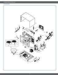
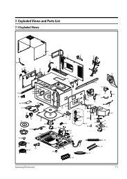
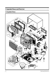
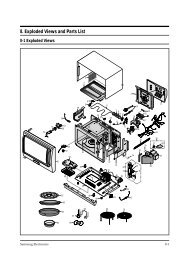
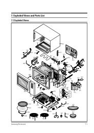
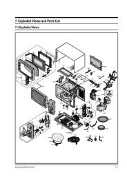
7. Exploded Views and Parts List<br />
7-1 Exploded Views<br />
T026<br />
T009<br />
T030<br />
T032<br />
M054<br />
T010<br />
T026<br />
W006<br />
T030<br />
T001<br />
T017<br />
M034<br />
W003<br />
M048<br />
M005<br />
M113<br />
M051<br />
M053<br />
M047<br />
M049<br />
M095<br />
M046<br />
23<br />
M008<br />
M038<br />
H008<br />
M010<br />
B018<br />
M045<br />
M011<br />
M012<br />
M039<br />
M013<br />
M001<br />
P186<br />
M015<br />
B006<br />
B001<br />
H018<br />
B011<br />
M041<br />
M040<br />
B002<br />
M023<br />
B010<br />
M042<br />
M036<br />
B024<br />
P109<br />
M019<br />
M037<br />
H013<br />
M058<br />
M035<br />
W002
7. Exploded Views and Parts List<br />
7-2 Main Parts List<br />
(S.N.A : SERVICE NOT AVAILABLE)<br />
Level No. Code No. Description Specification Q’ty SA/SNA Remark<br />
1-1 M041 0402-001554 DIODE-RECTIFIER HV03-12T01,12000V,0.4A,D 1 SNA P--B/PLATE<br />
1-1 M039 2501-001015 C-OIL 1.0uF,2100V,BK,35X54X80,20mm 1 SA P--B/PLATE<br />
1-1 M019 3601-001197 FUSE-CARTRIDGE 250V,15A,SLOW-BLOW,CERAMI 1 SA P--N/F<br />
1-1 M036 4713-001046 LAMP-INCANDESCENT 240V,104mA,25W,ORG,-,- 1 SA M--CV/AIR<br />
1-1 H008 6031-001424 WASHER-PLAIN PTFE,-,ID22.2,OD28,T1.7,WHT 1 SNA M--<br />
1-1 M038 DE26-00096A TRANS H.V SHV-EURO2-1,230V,50Hz,2350V,3. 1 SA P--<br />
1-1 M023 DE31-10155R MOTOR FAN -,230V50HZ,-,SMF-745EA1,2320RP 1 SA P--M/FAN<br />
1-1 M049 DE31-10170A MOTOR SYNCHRONOUS M2LJ24Z702,ST-16F,220/ 1 SA M--<br />
1-1 H018 DE31-90051A BLADE-FAN P.P,T,D130,-,-,-,- 1 SA P--M/FAN<br />
1-1 M054 DE32-10013A SENSOR THERMISTOR PT-312-K2,-,-,-,-,-,- 1 SA M--<br />
1-1 M095 DE47-00001A HEATER SHG-2933E,-,-,1300W(1250W),-,2 1 SA M--<br />
1-1 H013 DE47-20009A THERMOSTAT PW2N-520PB,160/60,250V/7.5A,H 1 SA P--MGT<br />
1-1 M053 DE61-00623A GUIDE-AIR -,SECC(PHOSPHATE),T0.5,-,-,-,E 1 SA M--<br />
1-1 P109 DE61-10006B COVER-MOTOR M1D33CE/XSA.RAD,PP(FB53),-,- 1 SA P--<br />
1-1 M113 DE61-30006A SUPPORT-HEATER -,ALUMINA,5G,2ND-W/P,-,-, 1 SNA M--<br />
1-1 M010 DE61-50021A BRACKET-FLANGE -,SECC1,T0.8,32,32,-,- 1 SA M--<br />
1-1 M012 DE61-50027B BRACKET-HEATER -,SECC,T1.0,W51,L55,CE945 1 SA M--<br />
1-1 M040 DE61-50106A BRACKET-HVC -,SECC,T0.8,W31,L125.8,-,- 1 SNA P--B/PLATE<br />
1-1 M013 DE61-50570C BRACKET-AIR GUIDE CK95,SECC,T0.8,-,-,-,D 1 SA M--<br />
1-1 M005 DE61-70060A SPRING-PLATE -,SK-5,T0.5,-,-,-,-,-,-,-,- 1 SA M--<br />
1-1 M051 DE63-00237A COVER-CEILING CE297DN-5,MICA-SHEET,T0.3, 1 SA M--<br />
1-1 P186 DE63-00240A COVER-BACK EU-1.0 CONV,SECC/PHOSPHATE,T0 1 SA M--<br />
1-1 M037 DE63-00248A COVER-AIR 5TH/1.0 CONVECTION,NYLON #66(T 1 SA M--<br />
1-1 M008 DE63-20017A GASKET-HEATER -,BRASS,T1.5,OD30.5,ID22.5 1 SA M--<br />
1-1 M001 DE64-01161G PANEL-OUTER 5TH/1.0 CONVECTION,SECC,T0.6 1 SA M--<br />
1-1 M058 DE65-20014A CABLE CLAMP -,-,-,NY-66,-,DA-6N 1 SNA P--P/CORD<br />
1-1 M034 DE67-00182A COUPLER 5TH-1.0,PPS,-,-,-,- 1 SA M--<br />
1-1 M042 DE91-70061A ASSY-H.V.FUSE THV060T-0800-H,5KV/0.80A,W 1 SA P--<br />
1-1 B018 DE96-00120Q ASSY BODY LATCH PG117R(TBMO/SIDE),NYLON 1 SA M--<br />
1-2 B002 3405-001032 SWITCH-MICRO 125/250VAC,16A,200GF,SPDT 1 SA MONITOR<br />
S/W<br />
1-2 B001 3405-001034 SWITCH-MICRO 125/250VAC,16A,200GF,SPST-N 2 SA DOOR S/<br />
W,PRIMARY<br />
S/W<br />
1-2 B024 DE96-00120T ASSY BODY LATCH-SUB PG117R(TBMO/SIDE),NY 1 SA<br />
1-3 B010 DE66-00093B LEVER-SWITCH(A) PG113R,NYLON,NTR,HANDLE, 1 SA<br />
1-3 B011 DE66-00094B LEVER-SWITCH(B) PG113R,NYLON,NTR,HANDLE, 1 SA<br />
1-3 B006 DE72-00137B LATCH-BODY PG113R,NYLON,WHT,-,-,-,-,- 1 SA<br />
1-1 M045 DE96-00295E ASSY BASE PLATE-SUB 5TH/1.0 CONVECTION,- 1 SA M--<br />
1-2 M046 DE60-60025A PIN-FOOT PP-JI350,BLK,-,-,-,-,-,- 1 SA<br />
1-2 M048 DE61-00557F BASE-PLATE 5TH/1.0 CONVECTION,SGCC,T0.6, 1 SNA<br />
1-2 M047 DE61-40065A FOOT -,PP,T2x22x17mm,BLK,-,-,- 1 SA<br />
1-1 W003 DE96-00296A ASSY-WIRE HARNESS B CE1100/XEF,CONVECTIO 1 SA M--<br />
1-1 W002 DE96-00359A ASSY-WIRE HARNESS A C100-5TH,CONVECTION 1 SA M--<br />
1-1 M015 DE96-00385A ASSY POWER CORD EU(ST),EURO,230V/50HZ,TL 1 SA P--<br />
24
7. Exploded Views and Parts List<br />
7-2 Main Parts List (Continued)<br />
(S.N.A : SERVICE NOT AVAILABLE)<br />
Level No. Code No. Description Specification Q’ty SA/SNA Remark<br />
1-2 W006 DE39-40409A WIRE HARNESS-E 230V50HZ,M9G45,CTW,-,-,- 1 SA<br />
1-2 M011 DE61-50347A BRACKET-EARTH -,BSS2-A,T1.0,W35,L43,MBGF 1 SA<br />
1-2 T001 DE74-20015G TRAY-COOKING 3RD-1.0,T6,1115G,HKS,-,-,-, 1 SA<br />
1-2 T032 DE97-00216E ASSY-WIRE RACK C100,HIGH-RACK/LOW-RACKAS 1 SA<br />
1-3 T009 DE97-00136B ASSY-WIRE RACK CK95,LOW-RACK,-,-,-,- 1 SA<br />
1-4 T030 DE74-00018B RACK-WIRE MSWR10,D268,CK95,-,H35,SNC2,LO 1 SNA<br />
1-4 T026 DE61-40022B FOOT-RACK -,SILICONE,1G,DARKVIOLET,-,-,- 1 SA<br />
1-3 T010 DE97-00136E ASSY-WIRE RACK MG104WA,114,FOOT,VE-TYPE 1 SNA<br />
1-4 T030 DE74-00018D RACK-WIRE MSWR10,PI3.0,3RD-1.0,-,110,SNC 1 SNA<br />
1-4 T026 DE61-40022B FOOT-RACK -,SILICONE,1G,DARKVIOLET,-,-,- 1 SA<br />
1-2 T017 DE97-00222A ASSY-GUIDE ROLLER NC-1.2CUFT,SPS(C832) B 1 SA<br />
1-1 M035 OM75P(31)MTMN ASSY-MGT 1 SA P--<br />
25
7. Exploded Views and Parts List<br />
7-3 Door Parts List<br />
D002<br />
D049<br />
(S.N.A : SERVICE NOT AVAILABLE)<br />
D024<br />
D021<br />
Level No. Code No. Description Specification Q’ty SA/SNA Remark<br />
1-1 D049 DE94-00644M ASSY DOOR C100-5,WHT,5th. 1.0 Convection 1 SA M--<br />
1-2 D006 DE64-40012C DOOR-C CK95,PBT,-,-,-,-,BLK,- 1 SA<br />
1-2 D002 DE64-40319A DOOR-A CK95,PC,-,-,-,-,WHT,- 1 SA<br />
1-2 D021 DE64-90160A DECORATION-DOOR -,Y745STC,S7A77,-,-,-,-, 1 SA<br />
1-2 D024 DE67-20184K SCREEN-DOOR(B) -,CK920T,TEMP GLASS,T3.2, 1 SA<br />
1-2 D047 DE94-01031A ASSY DOOR-E(SEALANT) 5TH/1.0 CONVECTION, 1 SA<br />
1-2 D011 DE64-00264B KEY-DOOR 1.0 CONV,NYLON#66,-,-,BLK,-,- 1 SA<br />
1-2 D043 DE63-00205A CUSHION-SCREEN C115,PC,T2.0,W12,L150,-,- 1 SNA<br />
1-2 D007 DE61-00198A SPRING-KEY M1877,HSWR,PI0.7,-,D6,23 1/4, 1 SA<br />
D047<br />
26<br />
D009<br />
D010<br />
D011<br />
D006<br />
D007
7. Exploded Views and Parts List<br />
7-4 Control Parts List<br />
C082<br />
C043<br />
C011<br />
C012<br />
C041<br />
(S.N.A : SERVICE NOT AVAILABLE)<br />
C009<br />
C045<br />
Level No. Code No. Description Specification Q’ty SA/SNA Remark<br />
1-1 C082 DE94-00646V ASSY CONTROL-BOX -,C100-5R/BWT,PC/WHT,5t 1 SNA M--<br />
1-2 C071 DE63-00088A COVER-LED C100,PUT-FORM,-,-,-,-,-,-,CK95 1 SA<br />
1-2 C025 DE64-00370A KNOB CK95(VI),PC,-,-,-,-,PURE-WHT,- 1 SA<br />
1-2 C045 DE64-00371A BUTTON-MORE CK95(VI),PC,-,-,PURE-WHT,1 B 1 SA<br />
1-2 C043 DE64-00372B BUTTON-DEFROST C100-R/BWT,PC,-,-,PURE-WH 1 SA<br />
1-2 C011 DE64-00373A BUTTON-SELECT(A) CK95(VI),PC,-,-,PURE-WH 1 SA<br />
1-2 C041 DE64-00374B BUTTON-CANCEL C100-R/BWT,PC,-,-,PURE-WHT 1 SA<br />
1-2 C012 DE64-00375A BUTTON-SELECT(B) CK95(VI),PC,-,-,PURE-WH 1 SA<br />
1-2 C001 DE94-00647B ASSY CONTROL-PANEL -,C100-R/BWT,-,RUSSIA 1 SA<br />
1-3 C005 DE64-00369B CONTROL-PANEL C100-R/BWT,PC,-,-,-,-,PURE 1 SA<br />
1-3 C009 DE67-40173B WINDOW-DISPLAY RE-MF70,SAN-20%(CR5381G01 1 SA<br />
1-2 C003 RCS-C100-04 ASSY PCB PARTS C100-5/XEE,230V50HZ 1 SA<br />
27<br />
C005<br />
C071<br />
C002<br />
C025<br />
C003
7. Exploded Views and Parts List<br />
7-5 Casing Parts List<br />
H010<br />
H008<br />
(S.N.A : SERVICE NOT AVAILABLE)<br />
H005<br />
H002<br />
H004<br />
H007<br />
Level No. Code No. Description Specification Q’ty SA/SNA Remark<br />
1-1 H005 DE97-00472A ASSY-COVER CASING -,5TH/1.0 CONVECTION,2 1 SA M--<br />
1-2 H001 DE31-10171A MOTOR CONVECTION SMC-105EA,230V/50HZ,280 1 SA<br />
1-2 H002 DE31-90019A BLADE-FAN SECC,T0.6,-,-,-,-,- 1 SA<br />
1-2 H002 DE31-90020A BLADE-FAN ALSTAR,T0.6,W250,L250,-,-,- 1 SNA<br />
1-2 H003 DE47-70077A HEATER-CONVECTION SHC-118E1,-,-,1680W,-, 1 SA<br />
H003<br />
1-2 H010 DE60-30016B NUT-FLANGE M4,MSWR10,FEFN,-,-,-,-,-,- 2 SA MOTOR-<br />
CONV,HEATER-CONV<br />
1-2 H011 DE60-40014B WASHER-C MOTOR M16,T1.0,SECC,ZNC3,-,-,-, 1 SA<br />
1-2 H008 DE60-40026B WASHER-PLAIN ID5.5,OD12,T1.0,SBC1,ZNC3,- 1 SNA<br />
1-2 H004 DE61-50484A BRACKET-HEATER -,STS430,T0.8,W27.2,L26,C 1 SA<br />
1-2 H007 DE72-30016B BUSH-MOTOR -,MSWR3,L15.7,D5.6,CE115K,-,- 1 SA<br />
1-2 H005 DE97-00491A ASSY-COVER CASING 1.0 CONVECTION,5TH/TSE 1 SA<br />
1-3 H014 DE61-00624A BRACKET-CASING -,ALCOAT-2,T0.6,-,-,-,EUR 1 SA<br />
1-3 H006 DE62-00029A ADIABATIC-CASING C115,FINE GLASS WOOL,T0 1 SNA<br />
1-3 H015 DE63-00239A COVER-CASING SECC,-,T0.5,-,-,-,-,-,EU 1. 1 SA<br />
1-2 Z009 DE91-70101C ASSY-THERMOSTAT MW5574W,160/60,187-HORIZ 1 SNA<br />
1-3 H013 DE47-20009A THERMOSTAT PW2N-520PB,160/60,250V/7.5A,H 1 SA<br />
1-3 H012 DE61-50490A BRACKET-TCO -,SECC1,T0.6,34,58,-,- 1 SNA<br />
28<br />
H002<br />
H006 H014H015<br />
H005<br />
H010<br />
H001<br />
H011<br />
H012<br />
Z009<br />
H013
7. Exploded Views and Parts List<br />
7-6 Standard Parts List<br />
(S.N.A : SERVICE NOT AVAILABLE)<br />
Level Code No. Description Specification Q’ty SA/SNA Remark<br />
1-1 6001-000033 SCREW-MACHINE TH,M4X10,STS304 1 SNA M--SENSOR<br />
1-1 6002-001079 SCREW-TAPPING TH,+,-,2S,M4,L10,PASS,STS3 1 SNA M--C/CEILING<br />
1-1 6002-001320 SCREW-TAPPING TH,+,2S,M4,L8,PASS,STS304, 1 SNA M--B/HEATER<br />
1-1 6002-001321 SCREW-TAPPING PWH,+,2S,M5,L10,ZPC(YEL) 2 SNA M--HVT,P--MGT<br />
1-1 6002-001325 SCREW-TAPPING TH,TORX,2S,M4,L12,ZPC(YEL) 2 SNA P--P/CORD,M--BKT<br />
A/GUIDE<br />
1-1 6006-001170 SCREW-ASSY TAPP WS,TH,+,M4,L10,ZPC(YEL) 4 SNA P--P/CORD,P--O/PANEL<br />
SIDE,P--N/F,M--W<br />
1-1 6006-001171 SCREW-ASSY MACH WS,PH,+,M4,L8,NI PLT 1 SNA M--B/EARTH<br />
1-1 6006-001174 SCREW-ASSY TAPP WE,TH,+,M4,L12,ZPC(YEL) 9 SA M--COVER CASING,M--<br />
GUIDE-AIR,M--PN/OU<br />
1-1 6006-001176 SCREW-ASSY TAPT WT,PH,+,M4,L8,ZPC(YEL) 3 SNA P--TCO,P--HVD,M--M/<br />
DRIVE<br />
1-1 DE60-10193A SCREW-TAPPING -,YEL,MSWR18,FEFZY,TH,M4,- 1 SNA P--M/FAN<br />
1-1 DE60-30016A NUT-FLANGE M4,MSWR10,-,-,-,-,-,-,- 1 SNA M--SENSOR<br />
1-2 6002-001320 SCREW-TAPPING TH,+,2S,M4,L8,PASS,STS304, 2 SNA BKT-HEA-CONV,TCO-<br />
CONV<br />
1-2 DE60-30016B NUT-FLANGE M4,MSWR10,FEFN,-,-,-,-,-,- 2 SA MOTOR-CONV,HEATER-<br />
CONV<br />
1-3 6002-001320 SCREW-TAPPING TH,+,2S,M4,L8,PASS,STS304, 1 SNA<br />
1-2 6002-001079 SCREW-TAPPING TH,+,-,2S,M4,L10,PASS,STS3 1 SNA C/MOTOR CONV<br />
1-2 6002-000170 SCREW-TAPPING PH,+,2S,M3,L6,ZPC(YEL),SWR 1 SNA BKT-TCO<br />
1-2 6002-000630 SCREW-TAPPING PH,+,2S,M3,L8,ZPC(YEL),SWR 1 SA<br />
29
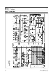
8. Schematic Diagrams<br />
8-1. Schematic Diagrams<br />
(This Document can not be used without Samsung’s authorization)<br />
<br />
<br />
<br />
<br />
<br />
<br />
<br />
<br />
<br />
<br />
<br />
<br />
<br />
<br />
<br />
<br />
<br />
<br />
<br />
<br />
<br />
<br />
<br />
<br />
<br />
<br />
<br />
<br />
<br />
<br />
<br />
<br />
<br />
<br />
<br />
<br />
<br />
<br />
<br />
<br />
<br />
<br />
<br />
<br />
<br />
<br />
<br />
<br />
<br />
<br />
<br />
<br />
<br />
<br />
<br />
<br />
<br />
<br />
<br />
<br />
<br />
<br />
<br />
<br />
<br />
<br />
<br />
<br />
<br />
<br />
<br />
<br />
<br />
<br />
<br />
<br />
<br />
<br />
<br />
<br />
<br />
<br />
<br />
<br />
<br />
<br />
<br />
<br />
<br />
<br />
<br />
<br />
<br />
<br />
<br />
<br />
<br />
<br />
<br />
<br />
<br />
<br />
<br />
<br />
<br />
<br />
<br />
<br />
<br />
<br />
<br />
<br />
<br />
<br />
<br />
<br />
<br />
<br />
<br />
<br />
<br />
<br />
<br />
<br />
<br />
<br />
<br />
<br />
<br />
<br />
<br />
<br />
<br />
<br />
<br />
<br />
<br />
<br />
<br />
<br />
<br />
<br />
<br />
<br />
<br />
<br />
<br />
<br />
<br />
<br />
<br />
<br />
<br />
30
9. Electrical Parts List<br />
9-1. Electrical Parts List<br />
(S.N.A : SERVICE NOT AVAILABLE)<br />
Level Code No. Description Specification Q’ty SA/SNA Remark<br />
1-2 RCS-C100-04 ASSY PCB PARTS C100-5/XEE,230V50HZ 1 SA<br />
1-3 3501-001155 RELAY-MINIATURE 24VDC,200MW,3000MA,1FORM 4 SA RY07,RY06,RY03,RY01<br />
1-3 3601-001126 FUSE-CARTRIDGE 250V,1.6A,FAST-ACTING,CER 1 SA FUSE<br />
1-3 DE07-00031B LED DISPLAY CSE-4258ESM1,C130,-,56SEG,8D 1 SA LED1<br />
1-3 DE26-00078A TRANS L.V SLV-C100,230V,50HZ,AC17.0V/6.8 1 SA LVT1<br />
1-3 DE30-20016A BUZZER CBE2220BA,STICK,-,-,-,-,-,-,- 1 SNA BUZ1<br />
1-3 DE34-00041A SWITCH-ENCODER 28VDC,10mA,ENDLESS,-,JES1 1 SNA ECD1<br />
1-3 DE47-40024A HOLDER-FUSE FH-51H,7.5A,-,-,-,-,- 1 SNA FUSE<br />
1-3 DE92-01267A ASSY PCB AUTO 230V50HZ,LED-MODULE,RC-C10 1 SNA<br />
1-4 0401-001083 DIODE-SWITCHING MM4148,100V,150MA,LL-34, 15 SNA D09,D10,D11,D04,D05,D06,D07,<br />
D08,D12,D<br />
1-4 0402-001080 DIODE-RECTIFIER GF1G,400V,1A,DO,TP 3 SNA D02,D03,D01<br />
1-4 0402-001298 DIODE-BRIDGE DF06S,600V,1A,SMD-4,TP 1 SNA BD01<br />
1-4 0403-001288 DIODE-ZENER ZMM55C5V1,4.8-5.4V,500MW,LL- 1 SNA ZD01<br />
1-4 0501-000465 TR-SMALL SIGNAL MMBT3904,NPN,350MW,SOT-2 1 SNA TR01<br />
1-4 0504-001080 TR-DIGITAL KRC246S,NPN,200mW,2.2K/<br />
10K,SO<br />
1-4 1202-000141 IC-VOLTAGE COMP. 7033,SOT-89,3P,-,SINGLE 1 SNA IC03<br />
1-4 1203-001037 IC-POSI.FIXED REG. 78L05,SOT-89,3P,185MI 1 SNA IC02<br />
31<br />
8 SNA TR02,TR03,TR04,TR05,TR06,TR<br />
07,TR08,TR<br />
1-4 1404-000230 THERMISTOR-PTC 27ohm,20%,-,265V,1.5A,360 2 SNA PTC2,PTC1<br />
1-4 2007-000033 R-CHIP 0ohm,5%,1/4W,TP,3216 14 SNA J06,J07,J08,J09,J10,J01,J02,J0<br />
3,J04,J<br />
1-4 2007-000277 R-CHIP 100Kohm,1%,1/8W,TP,2012 1 SNA R13<br />
1-4 2007-000300 R-CHIP 10Kohm,5%,1/8W,TP,2012 5 SNA R17,R16,R09,R08,R07<br />
1-4 2007-000468 R-CHIP 1Kohm,5%,1/8W,TP,2012 7 SNA R15,R14,R10,R05,R04,R03,R01<br />
1-4 2007-000671 R-CHIP 2Kohm,5%,1/8W,TP,2012 2 SNA R11,R02<br />
1-4 2007-000868 R-CHIP 4.7Kohm,1%,1/8W,TP,2012 1 SNA R12<br />
1-4 2007-000931 R-CHIP 470ohm,5%,1/8W,TP,2012 1 SNA R06<br />
1-4 2007-000941 R-CHIP 47Kohm,5%,1/8W,TP,2012 4 SNA R21,R18,R19,R20<br />
1-4 2203-000192 C-CER,CHIP 100nF,+80-20%,50V,Y5V,TP,2012 4 SNA C08,C09,C10,C11<br />
1-4 2203-000260 C-CER,CHIP 10nF,10%,50V,X7R,2012 2 SNA C12,C13<br />
1-4 2203-000444 C-CER,CHIP 1nF,10%,50V,X7R,2012 4 SNA C17,C16,C15,C14<br />
1-4 2203-000555 C-CER,CHIP 0.02NF,5%,50V,C0G,TP,2012 2 SNA C18,C19<br />
1-4 2401-000151 C-AL 1000uF,20%,25V,GP,TP,10x20,5 1 SNA C02<br />
1-4 2401-000244 C-AL 100uF,20%,10V,GP,TP,6.3x7,5 1 SNA C03<br />
1-4 2401-000598 C-AL 1uF,20%,50V,GP,TP,4x7,5 1 SNA C07<br />
1-4 2401-000911 C-AL 22uF,20%,16V,GP,TP,5x7,5 2 SNA C04,C06<br />
1-4 2401-001428 C-AL 470uF,20%,50V,GP,TP,10x20,5 1 SNA C01<br />
1-4 2401-002075 C-AL 4.7uF,20%,50V,GP,TP,5x11,5 1 SNA C05<br />
1-4 2801-003933 CRYSTAL-UNIT 8MHz,50ppm,28-AAA,12pF,70oh 1 SNA XTL1<br />
1-4 3404-001128 SWITCH-TACT 12VDC,50mA,160gf,6.6x6.6x6.8 14 SNA SW09,SW08,SW07,SW06,SW05,<br />
SW04,SW03,SW<br />
1-4 3711-001038 HEADER-BOARD TO<br />
CABLE<br />
1-4 3711-004143 CONNECTOR-<br />
HEADER<br />
BOX,6P,1R,2.5mm,ST 1 SNA CN04<br />
BOX,2P,1R,5MM,STRAIGHT, 1 SNA CN02
9. Electrical Parts List<br />
(S.N.A : SERVICE NOT AVAILABLE)<br />
Level Code No. Description Specification Q’ty SA/SNA Remark<br />
1-4 3711-004200 CONNECTOR-<br />
HEADER<br />
BOX,4P/7P,1R,2.5MM,STRA 1 SNA CN01<br />
1-4 DE41-00227A PCB-MAIN RC-C100-**,FR-1,1,-,-,T1.6*W19 1 SNA<br />
1-4 DE60-60012A PIN-EYELET ID2.1,OD2.5,L3.0,SN,BSP,T0.25 1 SNA<br />
1-3 DE09-00378A IC MICOM TMP87CH47U-5CD6,C100 - 5/<br />
XEF,4<br />
1 SNA IC01<br />
1-3 3501-001188 RELAY-POWER 24V DC,0.53W,-,1FORMA,9.3MS, 1 SA RY02<br />
1-3 3501-001209 RELAY-POWER 24V DC,0.53W,-,1FORMA,9.3MS, 2 SA RY05,RY04<br />
1-3 0202-000176 SOLDER-BAR VACULOY,-,22X337X16,96.5SN/3A 1 SNA<br />
1-3 0201-001822 ADHESIVE-STR 3629(LID4417),Pink,2500mPa. 1 SNA<br />
32
10. Wiring Diagrams<br />
10-1 Wiring Diagrams<br />
(This Document can not be used without Samsung’s authorization)<br />
BLK<br />
WHT<br />
MAGNETRON<br />
FA<br />
F<br />
HIGH VOLTAGE<br />
TRANSFORMER<br />
RED<br />
RED<br />
33<br />
HIGH VOLTAGE<br />
DIODE<br />
RED<br />
HIGH VOLTAGE CAPACITOR<br />
RED<br />
H.V.FUSE<br />
TO CHASSIS<br />
SYMBOL COLOR<br />
BRN BROWN<br />
BLK BLACK<br />
RED RED<br />
BLU BLUE
11. Reference<br />
11-1 Model name standard<br />
Baoad<br />
Classification<br />
Distinguisher<br />
USA CMO M<br />
USA RV R<br />
Middle<br />
Classfication<br />
CMO<br />
(Counter-top MWO)<br />
UTC<br />
(Under The Cabinet)<br />
Distinguisher<br />
34<br />
Product<br />
Code<br />
Full Nane<br />
W MW USA CMO (EPOXY CAVITY)<br />
U MU USA UTC<br />
Browner, Grill G MG USA GRILL<br />
Convection C MC USA CONVECTION<br />
Sensor S MS USA CMO SENSOR<br />
DC MWO D MD USA DC MWO<br />
Hospital MWO H MH USA Hospital MWO<br />
Ceramic Enamel E ME USA CMO (CERAMIC ENAMEL)<br />
SOLO M RM USA RV SOLO<br />
CONVECTION C RC USA RV CONVECTION<br />
BUILT-IN B RB USA RV BUILT-IN<br />
USA Junior SJ SJ USA Junior MWO<br />
USA OTR SM<br />
EUROPE<br />
Epoxy Cavity<br />
EUROPE<br />
Ceramic Enamel<br />
EUROPE<br />
Quartz GRILL<br />
EUROPE<br />
Power Grill<br />
EUROPE<br />
Convection<br />
EUROPE<br />
Fully Built-In<br />
M<br />
CE<br />
SOLO H SMH USA OTR SOLO<br />
CONVECTION V SMV USA OTR CONVECTION<br />
SOLO 1 M1 EUROPE SOLO (EPOXY CAVITY)<br />
GRILL 2 M2 EUROPE GRILL (EPOXY CAVITY)<br />
SOLO 1 CE1 EUROPE SOLO (CERAMIC ENAMEL)<br />
GRILL 2 CE2 EUROPE GRILL (CERAMIC ENAMEL)<br />
G2 G2 EUROPE Quartz GRILL<br />
PG PG POWER GRILL<br />
CK CK EUROPE CONVECTION<br />
C C EUROPE CONVECTION<br />
F<br />
SOLO W FW EUROPE SOLO FULLY BUILT-IN<br />
GRILL G FG EUROPE GRILL FULLY BUILT-IN<br />
CONVECTION C FC EUROPE CONVECTION FULLY BUILT-IN
11. Reference<br />
11-2 Customer inquiry cases and countermeasures<br />
Symptom Cause Countermeasures<br />
Air is evacuated from<br />
the oven.<br />
The oven works<br />
automatically<br />
whenever the power<br />
is turned on.<br />
Heating<br />
Ground<br />
Turn table<br />
occasionally rotates<br />
in reverse order.<br />
The oven sometimes<br />
beeps.<br />
• The vent of the oven<br />
is designed to be<br />
placed on the bottom<br />
of the product, and air<br />
is evacuated from the<br />
oven.<br />
• It may happen due<br />
to power failure or<br />
abnormal voltage.<br />
• It may happen when<br />
the door does not close<br />
completely.<br />
• In many cases, it<br />
may happen when<br />
the power level is<br />
incorrectly set.<br />
• It may happen when<br />
the door does not close<br />
completely.<br />
• It may happen when<br />
the oven is out of order.<br />
• Ground problem may<br />
happen when the oven<br />
is placed in a humid<br />
area and the over is<br />
not grounded.<br />
• Ground is not provided<br />
by an extended electric<br />
outlet.<br />
• Turntable has been<br />
designed to rotate in<br />
either direction since<br />
1994.<br />
• The oven beeps every<br />
minute unless the food<br />
is in the oven after<br />
the food is cooked<br />
completely.<br />
• The oven occasionally<br />
beeps during cooking.<br />
• In the past, the vent was placed on the back panel of<br />
the oven. Since the oven was placed near the wall of<br />
a kitchen, the wall behind the oven was discolored.<br />
Thus, the vent of a new oven is placed on the bottom<br />
of the product, and air is evacuated from the oven.<br />
• Connect the power plug three seconds after<br />
disconnecting the power plug.<br />
• Close the door completely => Press the Cancel button<br />
=> Press the Start button.<br />
• Select HIGH by rotating the Cooking Power Control<br />
knob.<br />
- KEEP WARM: This function is used to warm the<br />
cooked food for a certain time period, not to heat the<br />
food.<br />
- MEDIUM/LOW: This function is used to cook the food<br />
slowly.<br />
• Close the door completely. => Press the Cancel<br />
button. => Press the Start button.<br />
• Contact the nearest Samsung after-sales service<br />
center.<br />
• If the oven is placed in a humid area, buy an electric<br />
wire in a store selling electrical products. (Electric<br />
wires for home use are also allowed) Ground the oven<br />
through the electric wire.<br />
• Buy an electric wire in a store selling electrical<br />
products. (Electric wires for home use are also<br />
allowed) Ground the oven through the electric wire.<br />
• In the past, the gear of the turntable was easily worn<br />
by turning it during cleaning. Now, the turntable of the<br />
oven is designed to rotate in both directions to prevent<br />
damage during cleaning. (Rotation direction is set<br />
when the oven initially operates.)<br />
• Open and close the door again. (Beeping sounds<br />
indicate that the food is ready to be removed from the<br />
oven after cooking is complete.)<br />
35
11. Reference<br />
11-2 Customer inquiry cases and countermeasures (Continued)<br />
Symptom Cause Countermeasures<br />
Strange popping<br />
sounds are produced<br />
while fish is cooked.<br />
Strange smell is<br />
produced in the oven.<br />
Error<br />
Accessory<br />
Number does not<br />
appear on the display<br />
screen.<br />
• Since fish is salty and<br />
maintains its moisture,<br />
it is cooked while<br />
making a series of soft<br />
popping sounds. (The<br />
liquid may come out of<br />
the fish when the fish is<br />
cooked.)<br />
• It may happen when<br />
food particles stuck to<br />
oven walls or floor.<br />
• Errors are classified<br />
with Failure and Nonfailure.<br />
• It happens when the<br />
power saving function<br />
is activated.<br />
• Food with bones such as fish (e.g. mackerel) and pork<br />
(e.g. pork chops) is cooked while making a series of<br />
soft popping sounds. Wrap the food completely so that<br />
food particles or spattered oils do not stick to the oven<br />
walls or floor.<br />
• Clean the inside of the oven. => Remove strange<br />
smell through the Deodorant button => If the strange<br />
smell still remains, place a piece of lemon on the<br />
turntable and operate the oven for 5 minutes by<br />
pressing the Deodorant button.(However, the smells<br />
produced from the food exposed such as herbal<br />
remedies are not removed.)<br />
• Refer to the section of ERROR in User Manual.<br />
• Visit the nearest Samsung Service Center or local<br />
dealer to buy accessories. Before visiting, check the<br />
model name printed on the lower right side of the front<br />
panel of the oven.<br />
• Since the government recommends the reduction<br />
of electricity, the power saving function is performed<br />
for number display like that power cord is unplugged<br />
when the oven is not used. (Numbers are displayed<br />
when another button is pressed or when the door<br />
opens.)<br />
36
© Samsung Electronics Co., Ltd. June 2006<br />
Printed in Korea<br />
Code No. : DE68-04131A