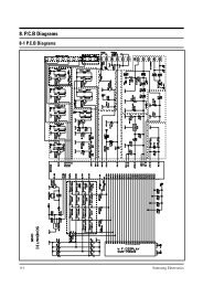
c100r-5d/bwt
c100r-5d/bwt
c100r-5d/bwt

You also want an ePaper? Increase the reach of your titles
YUMPU automatically turns print PDFs into web optimized ePapers that Google loves.
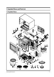
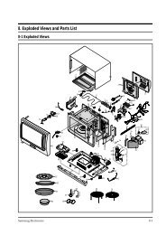
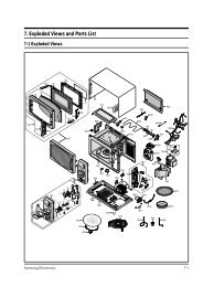
5. Alignment and Adjustments<br />
1. High voltage is present at the high voltage terminals during any cook cycle.<br />
2. It is neither necessary nor advisable to attempt measurement of the high voltage.<br />
3. Before touching any oven components or wiring, always unplug the oven from its power source and<br />
discharge the high voltage capacitor.<br />
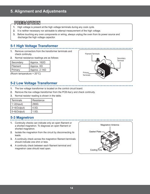
5-1 High Voltage Transformer<br />
1. Remove connectors from the transformer terminals and<br />
check continuity.<br />
2. Normal resistance readings are as follows:<br />
Secondary Approx. 162Ω<br />
Filament Approx. 0Ω<br />
Primary Approx. 2.14Ω<br />
(Room temperature = 20°C)<br />
5-2 Low Voltage Transformer<br />
1. The low voltage transformer is located on the control circuit board.<br />
2. Remove the low voltage transformer from the PCB Ass’y and check continuity.<br />
3. Normal resistor reading is shown in the table.<br />
Terminals Resistance<br />
1~2(Input) 290Ω.<br />
3~4(Output) 4.0Ω.<br />
5~6(Output) 1.0Ω.<br />
5-3 Magnetron<br />
1. Continuity checks can indicate only an open filament or<br />
a shorted magnetron. To diagnose an open filament or<br />
shorted magnetron.<br />
2. Isolate the magnetron from the circuit by disconnecting its<br />
leads.<br />
3. A continuity check across the magnetron filament terminals<br />
should indicate one ohm or less.<br />
4. A continuity check between each filament terminal and<br />
magnetron case should read open.<br />
14<br />
Filament Terminals<br />
Primary<br />
Terminals<br />
Gasket Plate<br />
Cooling Fins<br />
Magnetron Antenna<br />
Secondary<br />
Terminal