SAMSUNG CE959GT.pdf
SAMSUNG CE959GT.pdf
SAMSUNG CE959GT.pdf

Create successful ePaper yourself
Turn your PDF publications into a flip-book with our unique Google optimized e-Paper software.
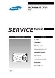
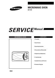
MICROWAVE OVEN<br />
<strong>CE959GT</strong> (DARK GRAY)<br />
SERVICE Manual<br />
Supplement<br />
THIS SUPPLEMENT CONTAINS EXPLODED VIEW AND PARTS LIST FOR MODEL <strong>CE959GT</strong>(DARK<br />
GRAY). FOR MORE SERVICING INFORMATION, PLEASE CONSULT THE PREVIOUS SERVICE<br />
MANUAL FOR CE959G WHICH WAS DISTRIBUTED IN JULY 1998.<br />
AMFO<br />
MICROWAVE OVEN CONTENTS<br />
1. 2. 3.<br />
1. 2. 3.<br />
1 min +<br />
Auto<br />
Auto<br />
Auto<br />
1. 2. 3.<br />
1. Precaution<br />
2. Control Panel<br />
3. Exploded View & Parts List<br />
4. P.C.B Diagram<br />
5. Schematic Diagrams<br />
Specifications<br />
TIMER 99 MINUTES 90 SECONDS<br />
POWER SOURCE 230V/50HZ, AC<br />
POWER CONSUMPTION MICROWAVE : 1,500W<br />
GRILL : 1,300W<br />
OUTPUT POWER FROM90 TO 900W<br />
OPERATING FREQUENCY 2,450MHz<br />
(10 LEVEL POWER)<br />
MAGNETRON OM75PH(31)<br />
(IEC-705 TEST PROCEDURE)<br />
COOLING METHOD COOLING FAN MOTOR<br />
OUTSIDE DIMENSIONS 517(W) x 297(H) x 410(D)<br />
NET WEIGHT 20 Kg<br />
SHIPPING WEIGHT 22 Kg
PRECAUTIONS TO BE OBSERVED BEFORE AND<br />
DURING SERVICING TO AVOID POSSIBLE<br />
EXPOSURE TO EXCESSIVE MICROWAVE ENERGY<br />
(a) Do not operate or allow the oven to be<br />
operated with the door open.<br />
(b) Make the following safety checks on<br />
all ovens to be serviced before activating<br />
the magnetron or other microwave<br />
source, and make repairs as necessary:<br />
(1) Interlock operation,<br />
(2) proper door closing,<br />
(3) seal and sealing surfaces (arcing,<br />
wear, and other damage),<br />
(4) damage to or loosening of hinges<br />
and latches,<br />
(5) evidence of dropping or abuse.<br />
(c) Before turning on microwave power<br />
for any service test or inspection within<br />
the microwave generating<br />
compartments, check the magnetron,<br />
wave guide or transmission line, and<br />
cavity for proper alignment, integrity,<br />
and connections.<br />
(d) Any defective or misadjusted<br />
components in the interlock, monitor,<br />
door seal, and microwave generation<br />
and transmission systems shall be<br />
repaired, replaced, or adjusted by<br />
procedures described in this manual<br />
before the oven is released to the owner.<br />
(e) A Microwave leakage check to verify<br />
compliance with the Federal<br />
performance standard should be<br />
performed on each oven prior to release<br />
to the owner.<br />
Samsung Electronics
1. Precaution<br />
Follow these special safety precautions. Although the microwave oven is completely safe during ordinary<br />
use, repair work can be extremely hazardous due to possible exposure to microwave radiation, as well as<br />
potentially lethal high voltages and currents.<br />
1-1 Safety precautions ( )<br />
1. All repairs should be done in accordance<br />
with the procedures described in this<br />
manual. This product complies with<br />
Federal Performance Standard 21 CFR<br />
Subchapter J (DHHS).<br />
2. Microwave emission check should be<br />
performed to prior to servicing if the oven is<br />
operative.<br />
3. If the oven operates with the door open :<br />
Instruct the user not to operate the oven and<br />
contact the manufacturer and the center for<br />
devices and radiological health immediatly.<br />
4. Notify the Central Service Center if the<br />
microwave leakage exceeds 5 mW/cm 2<br />
5. Check all grounds.<br />
6. Do not power the MWO from a "2-prong"<br />
AC cord. Be sure that all of the built-in<br />
protective devices are replaced. Restore any<br />
missing protective shields.<br />
7. When reinstalling the chassis and its<br />
assemblies, be sure to restore all protective<br />
devices, including: nonmetallic control<br />
knobs and compartment covers.<br />
8. Make sure that there are no cabinet openings<br />
through which people--particularly<br />
children--might insert objects and contact<br />
dangerous voltages. Examples: Lamp hole,<br />
ventilation slots.<br />
9. Inform the manufacturer of any oven found<br />
to have emmission in excess of 5 mW/cm 2,<br />
Make repairs to bring the unit into<br />
compliance at no cost to owner and try to<br />
determine cause.<br />
Instruct owner not to use oven until it has<br />
been brought into compliance.<br />
CENTRAL SERVICE CENTER<br />
10. Service technicians should remove their<br />
watches while repairing an MWO.<br />
11. To avoid any possible radiation hazard,<br />
replace parts in accordance with the wiring<br />
diagram. Also, use only the exact<br />
replacements for the following parts:<br />
Primary and secondary interlock switches,<br />
interlock monitor switch.<br />
12. If the fuse is blown by the Interlock Monitor<br />
Switch: Replace all of the following at the<br />
same time: Primary and secondary switches,<br />
as well as the Interlock Monitor Switch. The<br />
correct adjustment of these switches is<br />
described elsewhere in this manual. Make<br />
sure that the fuse has the correct rating for<br />
the particular model being repaired.<br />
13. Design Alteration Warning:<br />
Use exact replacement parts only, i.e., only<br />
those that are specified in the drawings<br />
and parts lists of this manual. This is<br />
especially important for the Interlock<br />
switches, described above. Never alter or<br />
add to the mechanical or electrical design<br />
of the MWO. Any design changes or<br />
additions will void the manufacturer's<br />
warranty.10.Always unplug the unit's AC<br />
power cord from the AC power source<br />
before attempting to remove or reinstall<br />
any component or assembly.<br />
14. Never defeat any of the B+ voltage<br />
interlocks. Do not apply AC power to the<br />
unit (or any of its assemblies) unless all<br />
solid-state heat sinks are correctly installed.<br />
15. Some semiconductor ("solid state") devices<br />
are easily damaged by static electricity. Such<br />
components are called Electrostatically<br />
Sensitive Devices (ESDs). Examples include<br />
integrated circuits and field-effect<br />
transistors.<br />
Immediately before handling any<br />
semiconductor components or assemblies,<br />
drain the electrostatic charge from your<br />
body by touching a known earth ground.<br />
16. Always connect a test instrument's ground<br />
lead to the instrument chassis ground before<br />
connecting the positive lead; always remove<br />
the instrument's ground lead last.<br />
Samsung Electronics 1-1
Pretaution<br />
1-2 Special Servicing Precautions (Continued)<br />
17. When checking the continuity of the witches<br />
or transformer, always make sure that the<br />
power is OFF, and one of the lead wires is<br />
disconnected.<br />
18. Components that are critical for safety are<br />
indicated in the circuit diagram by<br />
shading, or .<br />
19. Use replacement components that have the<br />
same ratings, especially for flame resistance<br />
and dielectric strength specifications. A<br />
replacement part that does not have the<br />
same safety characteristics as the original<br />
might create shock, fire or other hazards.<br />
1-3 Special High Voltage Precautions<br />
1. High Voltage Warning<br />
Do not attempt to measure any of the high<br />
voltages--this includes the filament voltage<br />
of the magnetron. High voltage is present<br />
during any cook cycle.<br />
Before touching any components or wiring,<br />
always unplug the oven and discharge the<br />
high voltage capacitor (See Figure 1-1)<br />
2. The high-voltage capacitor remains charged<br />
about 30 seconds after disconnection. Short<br />
the negative terminal of the high-voltage<br />
capacitor to the oven chassis. (Use a<br />
screwdriver.)<br />
3. High voltage is maintained within specified<br />
limits by close-tolerance, safety-related<br />
components and adjustments. If the high<br />
voltage exceeds the specified limits, check<br />
each of the special components.<br />
1-2<br />
Fig. 1-1. Discharging the High Voltage Capacitor<br />
Samsung Electronics
2. Control Panel<br />
Combi Button<br />
Grill Button<br />
Samsung Electronics<br />
1. 2. 3.<br />
1. 2. 3.<br />
1 min +<br />
1. 2. 3.<br />
Auto<br />
Auto<br />
Auto<br />
CE959G<br />
Auto Reheat Programs<br />
Auto Cook Programs<br />
Power Level Button<br />
Auto Defrost Programs<br />
More/Less Button<br />
Cancel Button<br />
Clock Setting Button<br />
Start Button<br />
2-1
2. Specifications<br />
2-1 Table of Specifications<br />
ITEM<br />
MODEL CE959G<br />
TIMER 99 MINUTES 90 SECONDS<br />
POWER SOURCE 230V/50HZ, AC<br />
POWER CONSUMPTION MICROWAVE : 1,500W<br />
GRILL : 1,300W<br />
OUTPUT POWER FROM90 TO 900W<br />
(10 LEVEL POWER)<br />
(IEC-705 TEST PROCEDURE)<br />
OPERATING FREQUENCY 2,450MHz<br />
MAGNETRON OM75PH(31)<br />
COOLING METHOD COOLING FAN MOTOR<br />
OUTSIDE DIMENSIONS 517(W) x 297(H) x 410(D)<br />
NET WEIGHT 20 Kg<br />
SHIPPING WEIGHT 22 Kg<br />
2-2 Comparison Chart<br />
FEATURE<br />
MODEL<br />
CE959G<br />
MORE/LESS O<br />
AUTO REHEAT O<br />
AUTO DEFROST O<br />
AUTO COOK O<br />
TIME COOK O<br />
POWER LEVEL (10) O<br />
CHILD LOCK O<br />
CLOCK O<br />
GRILL O<br />
COMBI O<br />
BEEPER ON/OFF O<br />
POWER LEVEL<br />
ON TIME OFF TIME<br />
% CE959G<br />
10% 90W 4 sec 26 sec<br />
20% 180W 7 sec 23 sec<br />
30% 270W 10 sec 20 sec<br />
40% 360W 13 sec 17 sec<br />
50% 450W 16 sec 14 sec<br />
60% 540W 19 sec 11 sec<br />
70% 630W 22 sec 8 sec<br />
80% 720W 25 sec 5 sec<br />
90% 810W 28 sec 2 sec<br />
100% 900W 30 sec 0 sec<br />
Samsung Electronics 2-1
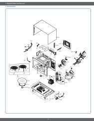
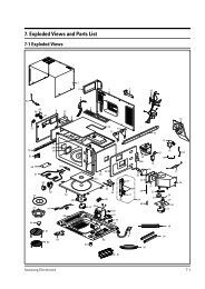
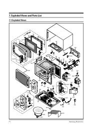
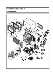
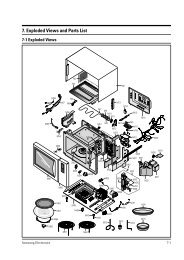
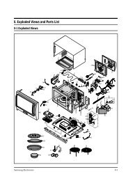
3. Exploded Views and Parts List<br />
3-1 Exploded Views<br />
D12<br />
C1<br />
D3<br />
D1<br />
D4<br />
C3<br />
C2<br />
D11<br />
D2<br />
C16<br />
D5<br />
C4<br />
C5<br />
D6<br />
D9<br />
D10<br />
M25<br />
C7<br />
M26<br />
C6<br />
C10<br />
C13 C9<br />
C8<br />
C11<br />
C12<br />
C15<br />
C14<br />
M34<br />
D8<br />
M35<br />
D7<br />
M36<br />
M32<br />
M1<br />
M39<br />
M41<br />
M22<br />
M20<br />
M3<br />
M33<br />
M2<br />
M42<br />
M21<br />
M19<br />
M12<br />
M37<br />
M28<br />
M11<br />
M27<br />
B1<br />
M41<br />
M4<br />
M45<br />
B2<br />
M13 M14<br />
M15<br />
M49<br />
M6<br />
M10<br />
B4<br />
M38<br />
M43<br />
M5<br />
M7<br />
3-1 Samsung Electronics<br />
M8<br />
B3<br />
B5<br />
M16<br />
M24<br />
M48<br />
M18<br />
M17<br />
M9<br />
M46<br />
M50<br />
M40<br />
M31<br />
M29<br />
M23<br />
M44<br />
M51<br />
M30<br />
M47
Exploded Views and Parts List<br />
4-2 Main Parts List<br />
Ref. No. Parts No. Description/Specification Q'ty Remarks<br />
M 1 DE70-30001C PANEL-OUTER;V/STEEL,T0.7,360,1128,STONE-GR 1<br />
M 2 DE63-90035G CUSHION-RUBBER;DFA20,T2,W190,L100,BLK 1<br />
M 3 DE61-50017A BRACKET-UPPER;SECC1,T0.6,340,216 1<br />
M 4 DE47-70031G HEATER-GRILL;D6.6,230V1280W,M9G45,SJH 1<br />
M 5 DE63-20017A GASKET-HEATER;BRASS,T1.5,OD30.5,ID22.5 1<br />
M 6 DE60-40009B WASHER-TEFLON;SLOT,ID22.2,OD28,T1.2,TEFLON 1<br />
M 7 DE61-50021A BRACKET-FLANGE;SECC1,T0.8,32,32 1<br />
M 8 DE61-50347A BRACKET-EARTH;BSS2-A,T1.0,W35,L43,MBGF45 1<br />
M 9 DE61-50027B BRACKET-HEATER;SECC,T1.0,W51,L55,CE945GF 1<br />
M 10 DE93-20020A ASSY BODY LATCH;RE-43B/90B 1<br />
M 11 DE73-90027A FERRITE-CORE;NI-ZN,T13.8,W21.0,L28.0,BNF-14 1<br />
M 12 DE26-10100A TRANS-H.V;SHV-945EG1,230V,2280V/3.15V,50 1<br />
M 13 2501-001030 C-OIL;1.1uF,2100V,BK,35x54x95,20mm 1<br />
M 14 DE61-50106A BRACKET-HVC;SECC,T0.8,W31,L125.8 1<br />
M 15 DE59-40001A DIODE-H.V;HVR-1X-32B-12 1<br />
M 16 DE91-70061A ASSY-H.V.FUSE;THV060T-0800-H,5KV/0.8A,WHT 1<br />
M 17 DE31-10156A MOTOR-FAN;SMF-945EA,230/50,2400,M97G45 1<br />
M 18 DE91-40095A ASSY NOISE FILTER;SN-E10D(N),250V,10A,2ND-WD-TYP 1<br />
M 19 DE61-40017A FOOT;PP(A353),BLK,MW5630T 2<br />
M 20 DE80-10001A BASE-PLATE;SGCC,T0.8,345,565, 1<br />
M 21 DE31-10154A MOTOR-DRIVE;M2HJ49ZR02,ST-16,21V,5/6 1<br />
M 22 DE71-60382A COVER-CEILING;MICASHEET,T0.5,70,133 1<br />
M 23 DE71-60016A COVER-AIR;PP,2,WHT,M945/M245 1<br />
M 24 4713-001031 LAMP-INCANDESCENT;230V,173mA,40W,ORG,-,-,25x69mm 1<br />
M 25 DE94-00024A ASSY DOOR;<strong>CE959GT</strong>-D,DARK-GRAY,AMFO 1<br />
M 26 DE94-00025A ASSY CONTROL-BOX;230V50HZ,<strong>CE959GT</strong>-D,DARK-GRAY,AMFO 1<br />
M 27 DE61-30006A SUPPORTER-HEATER;ALUMINA,5G,2ND-W/P 1<br />
M 28 DE61-70060A SPRING-PLATE;SK-5,T0.5 1<br />
M 29 DE61-50490A BRACKET-TCO;SECC1,T0.6,34,58 1<br />
M 30 DE03-30035A MAGNETRON;OM75PH((31)ESS 1<br />
M 31 DE47-20009A THERMOSTAT;PW2N-520PB,160/60,250V/7.5A,H, 1<br />
M 32 DE47-20161A THERMOSTAT;PW2N(120/110)187Z23.,250V/7.5A 1<br />
M 33 DE47-20008A THERMOSTAT;PW2N-52JC,100/60,250V/7.5A,H,1 1<br />
M 34 DE74-20015B TRAY-COOKING;GLASS,T6.0,PI318,1050G,MW5630T 1<br />
M 35 DE92-90189D ASSY-GUIDE ROLLER;D19,STD 1<br />
M 36 DE67-60075A COUPLER;PPS,7G,BRN,M97G45 1<br />
M 37 DE74-70003A RACK WIRE;MSWR3,3,290,125,SNC2,CE945G 1<br />
M 38 DE65-20014A CABLE CLAMP;DA-6N,NY-66 1<br />
M 39 DE72-60005A GUIDE-AIR;SECC1-P,T0.5,210,225 1<br />
M 40 DE92-90524A ASSY-COVER BACK;CE945G 1<br />
M 41 DE63-90065N CUSHION-GUIDE;PUT-FOAM,T10,W10,L200,BLK,MW55 2<br />
M 42 DE63-90065O CUSHION-GUIDE;PUT-FOAM,T35,W20,L135,BLK,MW55 1<br />
M 43 DE39-40409A WIRE HARNESS-E;230V50HZ,M9G45,CTW 1<br />
M 44 DE39-40568A WIRE HARNESS-A;230V50HZ,CE745G/CE945G 1<br />
M 45 DE39-20058C ASSY POWER CORD;KKP-4819D/B232,250V16A,L1700,G 1<br />
M 46 DE91-70101C ASSY-THERMOSTAT;MW5574W,160/60,187-HORIZ 1<br />
M 47 DE74-20107A TRAY BROILER;CE945GF(SSW),MW5574W 1<br />
Samsung Electronics<br />
3-2
3-3 Door Parts List<br />
3-4 Control Parts List<br />
3-5 Body Latch Parts List<br />
3-3<br />
Exploded Views and Parts List<br />
Ref. No. Parts No. Description/Specification Q'ty Remarks<br />
D 1 DE64-20112J HANDLE;ABS(HR0370),30G,-,-,-,D/GRAY,M959-D 1<br />
D 2 DE94-00013A ASSY DOOR-A;M959-D,D/GRAY 1<br />
D 3 DE64-40263P DOOR-A;ABS,-,M959-D 1<br />
D 4 DE64-40265D DOOR-SCREEN;ACRYL(IF850)ED17,M959 1<br />
D 5 DE92-50127H ASSY DOOR-E;COATING,BLACK,T0.8 1<br />
D 6 DE64-40012A DOOR-C;RESIN-PP(TB53),T2.0,CE945GF,BL 1<br />
D 7 DE01-00002A FILM-DOOR;PET,T0.15,275,175,NTR,CE945GF 1<br />
D 8 DE61-70126A SPRING-KEY;0.8,0,36,6,BLUING” 1<br />
D 9 DE64-40264C DOOR-KEY;POM(F20-02),5g,BLK,1,2ND,HANDL 1<br />
D 10 DE61-80003A HINGE-LOWER;SCP1,T2.3,26,77,ZPC3,WHT,CE945 1<br />
D 11 DE61-80002A HINGE-UPPER;SCP1,T2.3,26,77,ZPC3,WHT,CE945 1<br />
Ref. No. Parts No. Description/Specification Q'ty Remarks<br />
C 1 DE71-00002A COVER-PANEL;ABS(HR0370D),-,-,-,<strong>CE959GT</strong>-D,DARK-GRAY 1<br />
C 2 DE67-40145A WINDOW-DISPLAY;ACRYL,T2,W40,L77,SMOG,30G 1<br />
C 3 DE72-70211Q CONTROL-PANEL;ABS(HR0370D),WHT,-,-,<strong>CE959GT</strong>-D 1<br />
C 4 DE66-00001A BUTTON-SELECT(A);PC 1<br />
C 5 DE66-20197V BUTTON-SELECT(A-B);PC,-,-,M959-D,D/GRAY 1<br />
C 6 DE66-20198V BUTTON-SELECT(A-C);PC,-,-,M959-D,D/GRAY 1<br />
C 7 DE66-20179A BUTTON-SELECT;ABS(HR0370),NTR,30G,RE-445 1<br />
C 8 DE91-10537A ASSY PCB-MAIN;RC-959G-00,230V50Hz,VFD,CE959G 1<br />
C 9 DE66-20175L BUTTON-SELECT(B);ABS(HR0370),-,-,M959-D,D/GRAY 1<br />
C 10 DE66-20176L BUTTON-SELECT(C);ABS(HR0370),-,-,M959-D,D/GRAY 1<br />
C 11 DE66-20177M BUTTON-SELECT(D);ABS(HR0370),-,-,M959-D,D/GRAY 1<br />
C 12 DE66-20178M BUTTON-SELECT(E);ABS(HR0370),-,-,M959-D,D/GRAY 1<br />
C 13 DE64-10127F KNOB-COVER;ABS(HR0370D),-,<strong>CE959GT</strong>-D 1<br />
C 14 DE66-20182G BUTTON-START;ABS(HR0370D),-,-,DE959GT-D,DARK-GRAY 1<br />
C 15 DE71-60378A COVER-LAMP;POM,T2,W19.4,L27,3G,NTR,RE-446 1<br />
C 16 DE94-00021A ASSY CONTROL-PANEL;-,<strong>CE959GT</strong>-D,DARK-GRAY,AMFO 1<br />
Ref. No. Parts No. Description/Specification Q'ty Remarks<br />
B 1 DE66-40001A LATCH-BODY;POM(F20-02) 40GR NTR 1<br />
B 2 3405-000178 SWITCH-MICRO;VP-533A-OF-PS(T85) 250V,15A 2<br />
B 3 3405-000175 SWITCH-MICRO;VP-531A-OF(T85) 250V,15A,20 1<br />
B 4 DE66-90001A LEVER-SWITCH;P.O.M(F20-02) 2 6 NTR 2ND-W 1<br />
: Option Parts : Warning :Electrostatically Sensitive Devices<br />
Samsung Electronics
Exploded Views and Parts List<br />
3-6 Standard Parts List<br />
Parts No. Description / Specification Q'ty Remarks<br />
DE60-10012A SCREW-TAP TITE;TH,+,3,M4,L10,SWR10,ZPC2,TOOTH 1 N-F-EA<br />
DE60-10012A SCREW-TAP TITE;TH,+,3,M4,L10,SWR10,ZPC2,TOOTH 1 P-C-EA<br />
DE60-10012A SCREW-TAP TITE;TH,+,3,M4,L10,SWR10,ZPC2,TOOTH 1 S-M-EA<br />
DE60-10013A SCREW-ASSY TAP;TH,2S,4,L12,MSWR3,ZPC3,FIBER 1 MO/FAN<br />
DE60-10018A SCREW-ASSY MACHINE;PH,M4X0.7P,8,MSWR10,SN1,WS 2 B/EATH<br />
DE60-10024A SCREW-PH;PH,+,M4,L8,MSWR10,ZPC3 2 B/HEAT<br />
DE60-10045A SCREW-TAP PH;PH,M3,L6,FEFZY 2 MG-TCO<br />
DE60-10069A SCREW-TAP TH;TH,M4,L10,FRFZY 3 B/UPPE<br />
DE60-10069A SCREW-TAP TH;TH,M4,L10,FRFZY 1 CV/AIR<br />
DE60-10072A SCREW-TAP TH;TH,M4,L16,FEFZY,2-SLOT 1 CB-CMP<br />
DE60-10080A SCREW-WASHER;M5,L12,2S 4 MGT<br />
DE60-10080A SCREW-WASHER;M5,L12,2S 4 TNS-HV<br />
DE60-10082H SCREW-A;2S-4X12,TOOTHED 2 B-PLTE<br />
DE60-10082H SCREW-A;2S-4X12,TOOTHED 2 CN-BOX<br />
DE60-10082H SCREW-A;2S-4X12,TOOTHED 2 LATCH<br />
DE60-10082H SCREW-A;2S-4X12,TOOTHED 5 PN-OUT<br />
DE60-10098A SCREW-ASSY TAP TITE;PH,TC,M4X8,SWRCH18A,ZPC2,GLD,W 1 CV-TCO<br />
DE60-10098A SCREW-ASSY TAP TITE;PH,TC,M4X8,SWRCH18A,ZPC2,GLD,W 2 M/DRIV<br />
DE60-10122A SCREW-TAP TH;TAP,TH,2-4X8,FE,FN 2 C-CEIL<br />
DE60-20063A BOLT-FLANGE;M4,10,ZPC3,YEL,MSWR 2 HI-LOW<br />
DE60-20063A BOLT-FLANGE;M4,10,ZPC3,YEL,MSWR 2 HI-UPP<br />
DE60-10045A SCREW-TAP PH;PH,M3,L6,FEFZY 1 -<br />
DE60-10066A SCREW-TAP TH;TH,M4,L8,FEFZY,2-SLOT 2 H/DOOR<br />
DE60-10012A SCREW-TAP TITE;TH,+,3,M4,L10,SWR10,ZPC2,TOOTH 1 -<br />
DE60-10098A SCREW-ASSY TAP TITE;PH,TC,M4X8,SWRCH18A,ZPC2,GLD,W 1 -<br />
DE60-10088A SCREW-TAP PH;PH,M3,L8,FEFZY,PLAIN 12 CON/PANEL<br />
DE60-10045A SCREW-TAP PH;PH,M3,L6,FEFZY 1 GR-TCO<br />
Samsung Electronics<br />
3-4
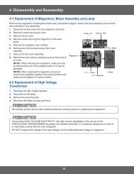
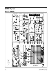
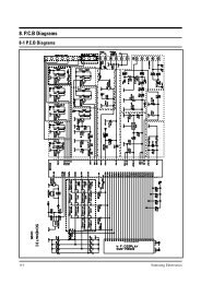
4. P.C.B Diagrams<br />
4-1 P.C.B Diagrams<br />
4-1 Samsung Electronics
4-2 P.C.B Parts List<br />
Parts No. Description / Specification Q'ty Remarks<br />
Samsung Electronics<br />
P.C.B Diagrams<br />
3501-001050 RELAY-MINIATURE;24VDC,200mW,5A,1FormA,10mS,5mS 2 RY02,RY03<br />
3501-001062 RELAY-POWER;24VDC,523.2mW,16A,1FormA,15mS 1 RY01<br />
3501-001068 RELAY-POWER;24Vdc,523mW,16A,1FormA,15mS,10 1 RY04<br />
DE07-10081A V.F.DISPLAY;SVM-4SM03,GRN/RSHORG,4,51,81.7 1 VFD1<br />
DE09-30725A IC-MCU;HD404316-D48S,CE959G 1 IC01<br />
DE26-20141A TRANS-L.V;SLV-945E,230V,50HZ,AC17/2.9V 1 LVT1<br />
DE30-20016A BUZZER;CBE2220BA,STICK 1 BUZ1<br />
DE39-40723A WIRE HARNESS;DC35V,C-959G,80mm,12PIN 1 CN05<br />
DE61-90320A HOLDER-DIGITRON;PP,-,W37,L83.3,-,CE959G 1 -<br />
DE91-20635A ASSY PCB AUTO-MAIN;230V50Hz,VFD,CE959G 1 -<br />
0401-001002 DIODE-SWITCHING;1N4148M,100V,200mA,500mW,3nS,D 11 D04~D14<br />
0402-001103 DIODE-RECTIFIER;1T4,400V,1A,TS-1,TP 3 D01~D03<br />
0403-000717 DIODE-ZENER;MTZJ5.1B,5.1V,4.94-5.2V,500mW 3 ZD01~ZD03<br />
0501-000388 TR-SMALL SIGNAL;KSC815,NPN,400mW,TO-92,BK,120 1 TR01<br />
0504-001014 TR-DIGITAL;KSR1005,NPN,300mW,4.7K-10K,TO- 5 TR02~TR06<br />
0504-001015 TR-DIGITAL;KSR2005,PNP,300mW,4.7K-10K,TO- 1 TR08<br />
2001-000037 R-CARBON(S);330ohm,5%,1/2W,AA,TP,2.4x6.4mm 2 R01,R02<br />
2001-000290 R-CARBON;10Kohm,5%,1/8W,AA,TP,1.8x3.2mm 4 R13,R14,R18,R19<br />
2001-000429 R-CARBON;1Kohm,5%,1/8W,AA,TP,1.8x3.2mm 7 R05,R06,R09~R11,R16,R17<br />
2001-000435 R-CARBON;1Mohm,5%,1/8W,AA,TP,1.8x3.2mm 1 R07<br />
2001-000613 R-CARBON;3.9Kohm,5%,1/8W,AA,TP,1.8x3.2m 2 R08R15<br />
2001-000780 R-CARBON;470ohm,5%,1/8W,AA,TP,1.8x3.2mm 3 R03,R04,R12<br />
2001-000786 R-CARBON;47Kohm,5%,1/8W,AA,TP,1.8x3.2mm 4 R22~R25<br />
2202-000127 C-CERAMIC,MLC-AXIAL;10nF,+80-20%,25V,Y5V,TP,-,7.5 2 C11,C12<br />
2202-000780 C-CERAMIC,MLC-AXIAL;100nF,+80-20%,50V,Y5V,TP,3.5x1 4 C07~C10<br />
2202-000796 C-CERAMIC,MLC-AXIAL;1nF,10%,50V,Y5P,TP,3.5x19 3 C15~C17<br />
2401-000247 C-AL;100uF,20%,10V,GP,-,6.3x11mm,5m 1 C03<br />
2401-000914 C-AL;22uF,20%,16V,GP,TP,5x11,5 2 C04,C06<br />
2401-001268 C-AL;4.7uF,20%,50V,GP,TP,5x11,5 1 C05<br />
2401-001412 C-AL;470uF,20%,35V,GP,TP,10x16,5 1 C01<br />
2401-001573 C-AL;47uF,20%,50V,GP,TP,6.3x11,2.5 1 C02<br />
2802-000161 RESONATOR-CERAMIC;4MHz,0.5%,TP,10.0x5.0x7.5mm 1 XTL1<br />
3404-000282 SWITCH-TACT;12Vdc,50mA,120+-30gf,6.2x3.6mm 10 SW01~SW10<br />
3711-000203 CONNECTOR-HEADER;1WALL,3P,1R,3.96mm,ANGLE,SN 1 CN01<br />
3711-000240 CONNECTOR-HEADER;1WALL,4P,1R,3.96mm,STRAIGHT,SN 1 CN02<br />
3711-000881 CONNECTOR-HEADER;BOX,3P,1R,2.5mm,STRAIGHT,SN 1 CN03<br />
DE13-20009A IC;KA7533,DIP 1 IC02<br />
DE39-60001A WIRE-SO COPPER;PI0.6,SN,T,52MM,TAPING_WIRE 14 J01~J03,J05~J15<br />
DE41-10463A P.C.B-MAIN;FR-1,T1.6,W89,L330,CE959G 1 -<br />
DE60-60012A PIN-EYELET;ID2.1,OD2.5,L3.0,SN,BSP,T0.25 5 -<br />
4-2
5. Schematic Diagrams<br />
5-1 Schematic Diagrams<br />
5-1<br />
POWER<br />
CORD<br />
230V/50HZ<br />
BRN BRN<br />
BLU<br />
GRILL<br />
TCO<br />
GRILL<br />
RELAY<br />
CAVITY<br />
TCO<br />
HEATER<br />
BLU<br />
WHT<br />
BLK<br />
BLU<br />
FUSE<br />
WHT<br />
CONDITION OF OVEN<br />
DOOR IS OPENED<br />
COOK OFF<br />
WIRING COLOR<br />
BRN : BROWN BLU : BLUE<br />
WHT : WHITE ORG : ORANGE<br />
RED : RED YEL : YELLOW<br />
BLK : BLACK<br />
Y/G : YELLOW GREEN<br />
BLK<br />
WHT<br />
250V10A<br />
C1<br />
ASSY CHOKE P.C.B<br />
1ND<br />
RESISTOR<br />
KEY BOARD<br />
C3<br />
C2<br />
NO<br />
COM<br />
L.V.T<br />
BLK<br />
BLK BLK<br />
PRIMARY LATCH<br />
SWITCH<br />
MAGNETRON<br />
FA<br />
BLK<br />
MGT<br />
TCO<br />
L.V.TRANS<br />
MAIN RELAY<br />
BLK<br />
NO<br />
COM<br />
L<br />
MAIN<br />
RELAY<br />
PRIMARYS/W<br />
POWER<br />
RELAY<br />
ORG<br />
ORG<br />
DOOR SENSING<br />
SWITCH<br />
FM<br />
A S S Y M A I N P.C.B<br />
F<br />
HIGH VOLTAGE<br />
TRANSFORMER<br />
BLK<br />
MONITOR FUSE<br />
(250V1.6A)<br />
RED<br />
RED<br />
230V40W<br />
YEL<br />
WHT<br />
COM<br />
BLK<br />
LAMP<br />
YEL<br />
F-MOTOR<br />
RED<br />
230V<br />
0V<br />
21V<br />
ORG<br />
BLK<br />
BLU<br />
WHT<br />
INRUSH<br />
RELAY<br />
ORG<br />
BLK<br />
DM<br />
D-MOTOR<br />
GRILL<br />
RELAY<br />
DOOR SENSING<br />
S/W<br />
NC WHT BLK<br />
COM NO<br />
BLK BLU<br />
BLK<br />
MONITOR<br />
SWITCH<br />
COM<br />
NC<br />
NO<br />
INRUSH RELAY<br />
RESISTOR<br />
BLU<br />
POWER RELAY<br />
(SECONDARY INTERLOCK)<br />
HIGH VOLTAGE<br />
DIODE<br />
YEL<br />
WHT<br />
HIGH VOLTAGE CAPACITOR<br />
RED<br />
H.V.FUSE<br />
H.V.TRANS<br />
BLK<br />
230V<br />
0V<br />
MAGNETRON<br />
SYMBOL COLOR<br />
BRN BROWN<br />
BLK BLACK<br />
RED RED<br />
BLU BLUE<br />
H.V.DIODE<br />
H.V.FUSE (0.8A)<br />
H.V.CAPACITOR<br />
F<br />
FA<br />
1.INPUT : 230V<br />
2.DOOR : OPEN<br />
3.LAMP : ON<br />
4. : P.C.B PATTERN<br />
5. : P.C.B IN/OUT POINT<br />
TO CHASSIS<br />
Samsung Electronics
ELECTRONICS<br />
© Samsung Electronics Co., Ltd. November 1998<br />
Printed in Korea<br />
DE68-62706B