MOD. 65/40 CPE 65/70 CPE 90/40 CPE 90/80 CPE 70/70 ... - EMGA
MOD. 65/40 CPE 65/70 CPE 90/40 CPE 90/80 CPE 70/70 ... - EMGA
MOD. 65/40 CPE 65/70 CPE 90/40 CPE 90/80 CPE 70/70 ... - EMGA

Create successful ePaper yourself
Turn your PDF publications into a flip-book with our unique Google optimized e-Paper software.
Code 252.107.11<br />
~<br />
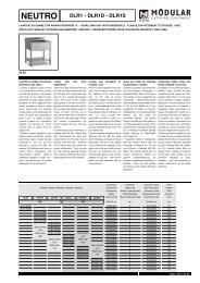
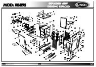
ELECTRIC PASTA COOKER<br />
<strong>MOD</strong>. <strong>65</strong>/<strong>40</strong> <strong>CPE</strong><br />
<strong>65</strong>/<strong>70</strong> <strong>CPE</strong><br />
<strong>90</strong>/<strong>40</strong> <strong>CPE</strong><br />
<strong>90</strong>/<strong>80</strong> <strong>CPE</strong><br />
<strong>70</strong>/<strong>70</strong> <strong>CPE</strong><br />
<strong>70</strong>/<strong>40</strong> <strong>CPE</strong><br />
110/50 <strong>CPE</strong><br />
110/<strong>80</strong> <strong>CPE</strong><br />
¸<br />
~
INDEX<br />
Paragraph Installation instructions<br />
1 Compliance with EEC directives<br />
1.1 Installation drawings<br />
1.2 Wiring diagrams<br />
1.3 Electrical specifications<br />
1.4 Technical data<br />
2 Preliminary installation instructions<br />
2.1 Regulations, technical rules and general specifications<br />
2.2 Installation<br />
2.2.1 Electrical connection<br />
2.2.1.1 Equipotential<br />
2.3 Water connection<br />
Paragraph User instructions<br />
3 Start-up<br />
3.1 Operating Instructions - Switching on and switching-off<br />
3.2 Emptying the tanks<br />
4 Maintenance, cleaning and care<br />
5 Declaration of conformity “CE” 252.062.01<br />
6 Declaration of conformity “CE” 252.063.01
INSTALLATION INSTRUCTIONS<br />
1 CONFORMITY WITH EEC DIRECTIVES<br />
REMARK: The electric pasta cooker are made in compliance with the basic requirements<br />
envisaged by EEC directives, in accordance with “EEC Directive 73/23 on low voltage”, “EEC<br />
Directive 89/336 on electromagnetic compatibility” and are marked “CE” according to the<br />
EEC Directive 93/68.
1.3 ELECTRICAL SPECIFICATIONS:<br />
Model<br />
Rated voltage<br />
<strong>70</strong>/<strong>40</strong> <strong>CPE</strong><br />
<strong>90</strong>/<strong>40</strong> <strong>CPE</strong> <strong>90</strong>/<strong>80</strong> <strong>CPE</strong><br />
<strong>40</strong>0V-3N~ 50/60 Hz<br />
Total power kW 9 9 18<br />
Power cable<br />
Cross section<br />
Dimensions mm<br />
Width<br />
Depth<br />
Height<br />
H05RN-F<br />
5 X 1.5 mm 2<br />
<strong>40</strong>0<br />
<strong>70</strong>0<br />
850 (9<strong>80</strong>)<br />
H05RN-F<br />
5 x 1.5 mm 2<br />
<strong>40</strong>0<br />
<strong>90</strong>0<br />
850 (1000)<br />
H05RN-F<br />
5 x 4 mm 2<br />
<strong>80</strong>0<br />
<strong>90</strong>0<br />
850 (1000)<br />
The data plate shows all the necessary data for the installation and can be found in the lower<br />
part in the front of the left-hand side panel.<br />
Model<br />
<strong>65</strong>/<strong>40</strong> <strong>CPE</strong> <strong>65</strong>/<strong>70</strong> <strong>CPE</strong> <strong>70</strong>/<strong>70</strong> <strong>CPE</strong><br />
Rated voltage<br />
<strong>40</strong>0V-3N~ 50/60 Hz<br />
Total power kW 6 9 9<br />
Power cable<br />
Cross section<br />
Dimensions mm<br />
Width<br />
Depth<br />
Height<br />
H05RN-F<br />
5 x 1.5 mm 2<br />
<strong>40</strong>0<br />
<strong>65</strong>0<br />
2<strong>80</strong> (<strong>40</strong>0)<br />
H05RN-F<br />
5 x 1.5 mm 2<br />
<strong>70</strong>0<br />
<strong>65</strong>0<br />
2<strong>80</strong> (<strong>40</strong>0)<br />
H05RN-F<br />
5 x 1.5 mm 2<br />
<strong>70</strong>0<br />
<strong>70</strong>0<br />
850 (9<strong>80</strong>)<br />
The data plate shows all the necessary data for the installation and can be found in the lower<br />
part on the rear of the left-hand side panel in the models <strong>65</strong>/<strong>40</strong> <strong>CPE</strong> and <strong>65</strong>/<strong>70</strong> <strong>CPE</strong>, and in<br />
the lower part in the front of the left-hand side panel in the model Mod. <strong>70</strong>/<strong>70</strong> <strong>CPE</strong>.<br />
Model 110/50 <strong>CPE</strong> 110/<strong>80</strong> <strong>CPE</strong><br />
Rated voltage <strong>40</strong>0V + 3N~ 50/60 Hz<br />
Total power kW 9 18<br />
Power cable H05RN-F H05RN-F<br />
Power cable<br />
Cross section<br />
5 x 1.5 mm 2 5 x 4 mm 2<br />
Dimensions mm<br />
Width<br />
500<br />
<strong>80</strong>0<br />
Depth<br />
1100<br />
1100<br />
Height<br />
850<br />
850<br />
The data plate shows all the necessary data for the installation and can be found on the front<br />
terminal block cover.
2. PRELIMINARY INSTALLATION INSTRUCTIONS<br />
The pasta cooker must be positioned in a well-aired room, if possible under a hood to<br />
remove cooking steam thoroughly.<br />
Before starting the appliance, remove all protective film; thoroughly clean the surfaces with a<br />
soft cloth, lukewarm water and detergent, so as to remove all anti-rust products applied<br />
during the manufacturing stage, then dry with a clean cloth.<br />
If the appliance is installed near walls, partition walls, kitchen furniture, decorative panelling,<br />
etc., these should be constructed with fireproof materials or a space of at least 100 mm<br />
should be left free.<br />
Make sure that fire prevention rules are strictly respected.<br />
The appliances can be positioned - according to the models - as top or ground appliances, or<br />
linked together with others of the series.<br />
The main switch and the socket must be near the appliance and easily accessible.<br />
Using the levelling feet lay the appliance flat, adjust the height and ensure its stability.<br />
2.1 Regulations, technical rules and general specifications<br />
Comply with the following rules during assembly:<br />
1) accident prevention rules;<br />
2) rules in force in the country where the appliance is installed;<br />
3) carefully read this booklet as it contains important instructions about installation safety,<br />
use and maintenance;<br />
4) keep this booklet for further reference.<br />
2.2 Installation<br />
Installation, setting up and maintenance must be carried out by qualified personnel only.<br />
Installation must be carried out in accordance with the rules in force in the country where the<br />
appliance is installed.<br />
The manufacturer declines all responsibility for incorrect functioning resulting from defective<br />
installation, tampering, improper use, bad maintenance, non-observance of the local rules<br />
and use by unskilled persons.<br />
INSTALLATION INSTRUCTIONS<br />
APPLIANCE WITH WEIGHT GREATER THAN <strong>40</strong> Kg<br />
BEFORE POSITIONING THE APPLIANCE CONNECT THE POWER CABLE TO THE<br />
TERMINAL BLOCK.
2.2.1 Electrical connection<br />
1) The electric pasta cookers are designed to operate off <strong>40</strong>0 VAC+3N voltage.<br />
2) The connection to the mains must be carried out through a suitably rated trip switch which<br />
has at least 3 mm between the contacts. Moreover, the mains voltage - when the<br />
appliance is working - must not exceed ± 10% of the voltage value.<br />
3) The power cable to connect the appliance to the mains must be at least equal to the<br />
H05RN-F rubber insulated type, with cross section suitable to the max. power<br />
consumption; therefore, its lowest cross section must comply to the data stated in the<br />
electrical specifications table for each type of appliance.<br />
4) On top appliances the cable inlet and the terminal block are on the rear side. To carry out<br />
the connection, unscrew and remove the protective cover.<br />
To gain access to the terminal block of the ground appliances, front panel must be<br />
removed: inside of the appliance you can reach the terminal block; to carry out the<br />
connection, insert the cable through the inlet gland and the cable-clamp and connect the<br />
wires to the relative binding posts.<br />
5) The appliance must be provided with an efficient earth connection.<br />
For this purpose, near the terminal block there is a binding post marked with the symbol<br />
to which the earth wire (yellow-green) must to be connected.<br />
The above-mentioned cable must be long enough so that – if the cable clamp loosens - it<br />
can be stressed only after the feed wires have been disconnected .<br />
NB: Earthing must be carried out according to the local standards and regulations in<br />
force.<br />
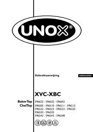
2.2.1.1 Equipotential connection<br />
When interconnecting multiple appliances together, the electric pasta cooker must be<br />
included in an equipotential system, whose efficiency has to be checked according to the<br />
rules in force. The connection is on the rear panel in top appliances, and on the left-hand<br />
side of the bottom frame in ground appliances, marked with “EQUIPOTENTIAL”.<br />
Earth wires for appliances<br />
Terminali cavetti di terra apparecchiatura
NB: The manufacturer declines all responsibility for damage resulting from noncompliance<br />
with accident prevention rules as described above.<br />
2.2.2 WATER CONNECTION<br />
To carry out a correct installation the following must be respected:<br />
1) The water feed pipes must be connected to the mains using cut off cocks which should<br />
always be closed when the pasta cooker is not being used or during maintenance<br />
interventions.<br />
2) A mechanical filter must be installed between the cut off cock and the pipes feeding the<br />
pasta cooker in order to avoid the build up of ferrous materials that when rusting could<br />
damage the stainless steel and lead to the presence of rust spots on the tank . You are<br />
therefore advised to drain off a small amount of water before attaching the last length of<br />
piping to the pasta cooker so washing away any eventual ferrous materials.<br />
3) If rust points do form on the tank this will be due to the build up of ferrous materials or the<br />
stagnant of iron filings. The stainless steel is not the cause.<br />
4) The water inlet can be found on the lower right-hand side of the pasta cooker. The water<br />
load pipe is marked with the symbol<br />
H2O<br />
Note: the manufacturer takes no responsibility and has no guarantee obligations for<br />
damage caused by not respecting the laws and standards in force or for a non<br />
professional installation.
USER OPERATING INSTRUCTIONS, SWITCHING ON<br />
Pasta cookers are appliances designed for cooking food and should be exclusively used by<br />
trained personnel following these operating instructions. Any other use of the appliance is to<br />
be considered improper and therefore dangerous.<br />
Before introducing food in the tank, you are advised to clean it carefully; wash with water and<br />
common detergents, then rinse well.<br />
3 PUTTING INTO OPERATION<br />
CAUTION: The appliance should only be used under the operator’s surveillance!!!<br />
The appliance must not be used with a water level below the basket support placed inside<br />
the tank.<br />
The user must make sure that the pavement on which the pasta cooker is installed is fitted<br />
with a floor drain to collect the water drained off from the tank overflow pipe.<br />
3.1 SWITCHING ON<br />
Make sure that the water drainage valve is closed. Fill the tank with water up to the maximum<br />
level (overflow opening), turn on the power by switching on the main switch installed ahead<br />
of the appliance.<br />
Rotate selector switch to the desired position 1, 2 or 3. The green pilot lamp indicates that<br />
the appliance is switched on.<br />
Note: Rotating the knob to position “1” the pasta cooker will function at minimal power; to<br />
position “2” it will function at two thirds power and in position “3” it will function at full power.
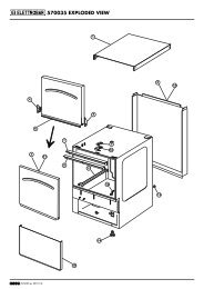
3.2 EMPTYING THE TANKS<br />
Top appliances:<br />
The operator must make sure that there is a suitable container available to collect the<br />
drained off water. Insert the drainage tube with bayonet joint as shown in the drawing. To<br />
drain off the water turn the lever as shown in the drawing.<br />
Ground appliances:<br />
Connect the tank drain to the floor drain.<br />
Turn the know of the drainage anti clock-wise to empty the bowl.<br />
When the tank is empty, turn the valve knob clockwise.<br />
4 MAINTENANCE, CLEANING AND CARE<br />
Before carrying out any cleaning operations disconnect the power at the mains.<br />
It is recommended that the installation be checked by an authorised technician at least twice<br />
a year, a special attention should be given to the efficiency of control and safety devices. .<br />
For the daily cleaning of the appliance, the steel parts must be cleaned using a smooth cloth,<br />
water and common detergents. After cleaning rinse well and dry thoroughly.<br />
If the appliance is not to be used for an extended period of time, clean all the stainless steel<br />
surfaces well using a cloth soaked in vaseline oil so as to apply a protective veil. Make sure<br />
the rooms are aired regularly.<br />
At all costs avoid casual or continuos contact with rusting materials which could cause<br />
corrosion spots to appear. Therefore ladles, mixers and spoons etc. must be made of<br />
stainless steel.<br />
For the same reason never clean the stainless steel using steel wool, brushes or scrapers,<br />
which are made of common steel. Stainless steel wire wool can be used but only rub with the<br />
grain.<br />
Once you have emptied the food from the tank, make sure that the tank is well cleaned in<br />
order to remove incrustations. Use nylon spatulas where possible.<br />
ATTENTION: Do not wash the appliance with direct water jets or with a high-pressure<br />
cleaner, as possible infiltration to the electrical parts could jeopardize the<br />
regular operation of the appliance and of the safety devices.