MOD. 90/40 FRG 22 90/80 FRG 22 110/40 FRG 22 GB-IE - EMGA
MOD. 90/40 FRG 22 90/80 FRG 22 110/40 FRG 22 GB-IE - EMGA
MOD. 90/40 FRG 22 90/80 FRG 22 110/40 FRG 22 GB-IE - EMGA

Create successful ePaper yourself
Turn your PDF publications into a flip-book with our unique Google optimized e-Paper software.
Code 252.191.11<br />
<strong>22</strong> - LITRE GAS FRYER - 9 LD SER<strong>IE</strong>S<br />
~<br />
<strong>MOD</strong>. <strong>90</strong>/<strong>40</strong> <strong>FRG</strong> <strong>22</strong><br />
<strong>90</strong>/<strong>80</strong> <strong>FRG</strong> <strong>22</strong><br />
<strong>110</strong>/<strong>40</strong> <strong>FRG</strong> <strong>22</strong><br />
¸ ~<br />
0051<br />
<strong>GB</strong>-<strong>IE</strong>– CAT. II2H3+
1. Warnings<br />
INDEX<br />
2. Compliance with the EEC Directives for gas appliances<br />
3. Installation diagrams<br />
4. Technical data table - Fryer<br />
4.1 Gas characteristics<br />
5.<br />
6. Instructions for the qualified installer<br />
6.1 Installing the appliance<br />
6.2 Laws, technical regulations and general rules<br />
6.3 Discharge of fumes for type ”A” appliances<br />
6.4 Discharge of fumes for type ”B” appliances<br />
6.5 Checking for gas leaks<br />
7. Maintenance<br />
7.1 Converting for use with a different type of gas – Fryer<br />
7.2 Changing spare parts - Fryer<br />
8. Instructions for the user<br />
8.1 Turning the fryer burner on<br />
8.2 Approximate temperatures of the valve knob<br />
8.3 Turning the fryer burners off<br />
8.4 Turning the fryer off completely<br />
8.5 Safety thermostat<br />
8.6 Filling the fryer with oil<br />
8.7 Draining the oil from the fryer<br />
9. Maintenance, cleaning and care<br />
10. Exploded functional parts table<br />
10.1 Draught diverter stack assembly diagram
THIS APPLIANCE HAS BEEN MADE FOR COOKING FOOD AND MUST ONLY BE<br />
USED BY PROFESSIONALLY SKILLED PERSONNEL IN THE WAY DESCRIBED IN<br />
THIS INSTRUCTION MANUAL.<br />
1. WARNINGS<br />
♦ Read this handbook through carefully as it provides important information for a safe<br />
installation, use and maintenance.<br />
♦ Keep this handbook in a safe place for future reference.<br />
♦ Only professionally skilled personnel must install the appliance and, if required, convert<br />
it to receive a different type of gas.<br />
♦ For any repairs needed call one of the manufacturer’s authorised technical assistance<br />
centres only and demand original spare parts.<br />
♦ The parts which have been sealed by the manufacturer must not be tampered with.<br />
Any adjustments (only for gas changeover) must be performed by professionally<br />
qualified personnel.<br />
Failure to observe the above could undermine the safety of the appliance.<br />
2. COMPLIANCE WITH THE “EEC” DIRECTIVES" – GAS APPLIANCES<br />
This appliance has obtained the “CE” type approval certificate as it complies with<br />
the acceptance tests carried out in accordance with the following standard:<br />
"ESSENTIAL REQUIREMENTS ANNEX I EEC DIRECTIVE <strong>90</strong>/396 MD 26/06/19<strong>90</strong>"
4. TECHNICAL DATA TABLE<br />
<strong>MOD</strong>EL<br />
BURNERS<br />
No. x kW<br />
BOWL<br />
CAPACITY<br />
L<br />
TOTAL<br />
POWER<br />
kW<br />
TOTAL GAS<br />
CONSUMPTION<br />
NATURAL<br />
LPG<br />
GAS<br />
G30 – G31<br />
G20<br />
kg/h<br />
m³/h<br />
DIAMETER OF NOZZLES IN<br />
HUNDREDTHS OF A MILLIMETRE<br />
NATURAL<br />
LPG<br />
GAS<br />
G30 – G31<br />
G20<br />
30 mbar 37mbar<br />
20 mbar<br />
<strong>90</strong>/<strong>40</strong> <strong>FRG</strong> <strong>22</strong> 4 x 3.4 <strong>22</strong> 13.6 1.07 1.439 100 145 DC<br />
<strong>90</strong>/<strong>80</strong> <strong>FRG</strong> <strong>22</strong> 8 x 3.4<br />
<strong>110</strong>/<strong>40</strong> <strong>FRG</strong> <strong>22</strong> 4 x 3.4<br />
<strong>22</strong> + <strong>22</strong> 27.2 2.14 2.878 100 145 DC<br />
<strong>22</strong> 13.6 1.07 1.439 100 145 DC<br />
NOZZLE FOR PILOT BURNERS 30 51<br />
4.1 GAS CHARACTERISTICS<br />
The data relative to powers and consumption refer to the following types of gas:<br />
TYPE OF GAS NET HEAT VALUE<br />
(NHV)<br />
PRESSURE<br />
mbar<br />
SUPPLY<br />
mm water<br />
G20 (natural gas) CH4 9.45 kW m³/h 20 200<br />
G30 (butane) C4H10 12.68 kW/kg 30 300<br />
G31 (propane) C3H8 12.87 kW/kg 37 370<br />
G25 (G20L – DE) 8.12 kW m³/h 20 200<br />
G25 (aardgas NL) 8.12 kW m³/h 25 250<br />
When installing the appliances, gas supply pressures must be those given above in order<br />
to have maximum burner efficiency.<br />
Pressures mbar: 1 millibar = 1 mbar = 10 mm water<br />
Power: 1 kW = 860 kcal = 3.6 MJ = 3412 BTU
6. INSTRUCTIONS FOR THE QUALIF<strong>IE</strong>D INSTALLER<br />
6.1 INSTALLING THE APPLIANCE<br />
• Take the unit out of the packaging. Check that it is in good condition. If in doubt, do not<br />
use it and contact professionally qualified personnel.<br />
Always place the unit under an aspiration hood. After installation, it will need to be<br />
levelled by using the feet.<br />
• Always use rigid galvanised steel or copper pipes for connecting the appliance.<br />
All the seals on the joining threads must be made using materials that are certified for<br />
use with gas.<br />
• If the appliance is wall mounted, in contact with flammable material, you will have to<br />
place a layer of heat-resistant insulating material between the appliance and the wall or<br />
leave a space of 200 mm between the appliance and the wall.<br />
• The gas system before the appliance, likewise the characteristics of the room in which<br />
the appliance is installed, must comply with current laws.<br />
• Before connecting the unit, you must check what kind of gas it is set up to use, and<br />
whether the gas which is available to power it is suitable. If the available gas is not<br />
suitable for the appliance, proceed as described in the paragraph "Changeover for<br />
operation with other types of gas".<br />
• Always install a cutoff cock between each appliance and the gas pipe.<br />
• Check that aeration in the room is sufficient when the appliance is working, considering<br />
that the necessary quantity of air for combustion is 2 m³/h of air for each kW of installed<br />
power.<br />
6.2 LAWS, TECHNICAL REGULATIONS AND GENERAL RULES<br />
• Standard UNI-CIG 8723, Ministerial circular no. 68 dated 25/11/69 and variations.<br />
• Accident prevention laws.
6.3 DISCHARGE OF FUMES FOR TYPE “A” APPLIANCES<br />
The appliances must be installed on premises that are suitable for the discharge of the<br />
products of combustion and must be in compliance with what is established by the<br />
installation rules. Our appliances are considered type “A” gas appliances (see the<br />
Technical Data Tables) and are not for connecting to a natural discharge duct for the<br />
products of combustion.<br />
These appliances must discharge through specific extractors, or similar devices,<br />
connected to a properly working flue or discharged directly outside.<br />
If this is not possible, an air suction device can be used connected directly to the outside,<br />
with a capacity that must be no less than that required plus the quantity of fresh air that is<br />
necessary for the well-being of the workers.<br />
6.4 DISCHARGE OF FUMES FOR TYPE “B” APPLIANCES<br />
The appliances must be installed on premises that are suitable for the discharge of the<br />
products of combustion and must be in compliance with what is established by the<br />
installation rules.<br />
The appliances must be installed on premises that are suitable for the discharge of the<br />
products of combustion and must be in compliance with what is established by the<br />
installation rules.<br />
Our appliances are considered (see the Technical Data Table) type B gas appliances, and<br />
are for connecting to a natural discharge duct for the products of combustion like, for<br />
instance, connected to an efficient natural draught flue or discharged directly outside or<br />
they can be interlocked with a forced discharge system, like a hood fitted with a<br />
mechanical extractor.<br />
If the products of combustion are discharged by means of a forced system:<br />
• the supply of gas to the appliance must be interlocked directly to the forced discharge<br />
system and must stop if the capacity of the system drops below the values prescribed. It<br />
must be only be possible to start the gas supply to the appliance by hand;<br />
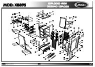
• If the appliance is installed under a hood, the end of the appliance’s discharge pipe<br />
must be at least 1.8 m from the surface on which the appliance is standing, the<br />
discharge pipe opening’s cross section must be inside the base perimeter of the hood.<br />
1,8 m<br />
FORCED DISCHARGE NATURAL DISCHARGE<br />
HOOD<br />
Chimney jack<br />
E: Electrical interlock<br />
NOTA: the chimney jack is<br />
supplied on request<br />
1,8 m<br />
draught<br />
diverter<br />
device<br />
NOTA: the draught diverter is<br />
supplied on request
6.5 CHECKING FOR GAS LEAKS<br />
Once installed, check there are no gas leaks on pipe joints using a soapy water solution.<br />
You will know if there are leaks by the foamy bubbles that form. Never use bare flames to<br />
check for leaks.<br />
When the appliance is ready to use, check there are no gas leaks, checking on the gauge,<br />
if used (for a time of 30 minutes), that there is no passage or consumption of gas.<br />
7. MAINTENANCE<br />
There is very little maintenance thanks to the correct way the appliances have been made.<br />
However, we do advise having the systems checked by qualified people at least twice a<br />
year.<br />
N.B.: the manufacturer declines all responsibility for direct or indirect damages<br />
caused by an incorrect installation, bad maintenance, tampering, improper<br />
uses and by the failure to comply with the accident prevention norms<br />
regarding the prevention of fire and safety for gas systems.<br />
7.1 CONVERTING FOR USE WITH A DIFFERENT TYPE OF GAS - FRYER<br />
The appliance is tested and set for working with gas according to the characteristics table<br />
affixed in proximity of the appliance’s gas inlet.<br />
If it has to work with a different type of gas, proceed as follows:<br />
• It must be converted by qualified personnel<br />
• The set of nozzles for changeover to another type of gas, different from the type for<br />
which the unit was set up, is normally contained in a nylon bag with relative additional<br />
labels that show all the types of gas.<br />
If the set is not provided, it must be requested from the dealer/importer, first<br />
ascertaining that the unit can in fact work with other types of gas.<br />
Once changeover and necessary adjustments are complete, the label for the<br />
corresponding gas must be place in the appropriate place on the characteristics tag,<br />
cutting out the correct one.<br />
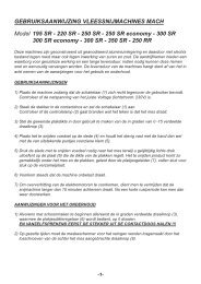
• Changing the burner nozzles (Fig. 1):<br />
open the compartment doors, change the nozzles (30) according to the type of gas<br />
(see the TECHNICAL DATA table).<br />
• Changing the pilot burner nozzle:<br />
remove the panel (20), unscrew the pilot burner nut and change the nozzle (19)<br />
according to the type of gas (see the TECHNICAL DATA table).
• Adjusting the burners, checking supply pressures and working order:<br />
once the nozzles have been changed, check that gas pressure, both in valve output<br />
and input, is as given in the TECHNICAL DATA table. To do this, remove the screw on<br />
the valve’s (1) pressure tap (11), insert a rubber pipe connected to a gauge and check<br />
pressure. If it is different to that specified, find the cause and correct it.<br />
• Adjusting the pilot burner:<br />
this burner needs no adjusting.<br />
• Regulating the minimum flame – burner:<br />
The valve has a on/off function so needs no adjusting.<br />
7.2 CHANGING SPARE PARTS - FRYER<br />
Thermostatic cock (1):<br />
Open the compartment doors, unscrew the inlet (2) and outlet (3) connection fittings.<br />
Unscrew the small pilot pipe fitting (4) and the thermocouple (5). Pull the thermostat bulb<br />
(6) out from the bowl after having emptied it of oil and having unscrewed the nut (7).<br />
Change the valve and put everything back in place checking for oil leaks on the thermostat<br />
(6) with hot oil in the bowl.<br />
Safety thermostat (8)<br />
drain the oil from the bowl, unscrew the nut (9), extract the thermostat bulb (10) and<br />
change the thermostat. Put everything back in place checking for oil leaks on the<br />
thermostat bulb (10) with hot oil in the bowl.<br />
Thermocouple (5):<br />
unscrew the thermocouple (5) from the valve (1) and from the pilot (18) and then change it.<br />
Ignition plug (21):<br />
Unscrew the plug securing nut (21) on the pilot and change the plug.<br />
Piezoelectric lighter (13):<br />
pull the plug connecting cable out, remove the valve cap (1) where the piezoelectric lighter<br />
is inserted, and change it.<br />
Changing the pilot (14):<br />
Unscrew the two burner securing screws on the bowl, unscrew the nut (15) securing the<br />
burner to the gas distribution shaft. Change the burner and then put everything back in<br />
place.<br />
N.B.: After each change or repair, check that the parts changed are working properly and<br />
adjust them if necessary.<br />
Check for leaks on the gas pipe fittings with a soapy water solution – never use a bare<br />
flame.
8. INSTRUCTIONS FOR THE USER<br />
8.1 LIGHTING THE FRYER BURNERS<br />
Lighting the pilot flame:<br />
Make certain that the thermostatic safety valve knob is in the CLOSED position (<br />
symbol). Press the push button right down and, holding it pressed, press the<br />
piezoelectric lighter push button at the same time. The pilot flame lights automatically.<br />
Check the flame is lit through the holes (21) on the appliance panel.<br />
Keep the valve push button (24) pressed for 10-15 minutes to heat the thermocouple and<br />
then let it go.<br />
Repeat this operation if the burner goes out.<br />
Lighting the burners and adjusting the temperature:<br />
Once the pilot flame is lit, turn the thermostatic safety valve (6) knob (<strong>22</strong>) into the position<br />
minimum 1 to maximum 8 (the other numbers represent the intermediate temperatures).<br />
The burners light automatically and once the temperature is reached you set with the<br />
knob, the thermostatic valve turns the burners off, lighting them again when the<br />
temperature drops.<br />
8.2 APPROXIMATE TEMPERATURE OF THE VALVE KNOB<br />
ITEM 1/100°C ITEM 2/<strong>110</strong>°C ITEM 3/125°C<br />
ITEM 4/135°C ITEM 5/145°C ITEM 6/160°C<br />
ITEM 7/170°C ITEM 8/1<strong>80</strong>°C<br />
Tolerance ± 10%<br />
8.3 TURNING THE FRYER BURNERS OUT<br />
Turn the knob round to the position. The burners will go out, leaving only the pilot<br />
flame alight.<br />
8.4 TURNING THE FRYER OFF COMPLETELY<br />
Press the push button right down (23) and then let it go. This stops gas reaching the<br />
burners and the pilot burner. This button will stay down automatically for 1 minute after<br />
which it returns to its initial position. Only now can the fryer be turned on again, repeating<br />
the steps from the beginning.<br />
8.5 SAFETY THERMOSTAT<br />
Besides the thermostatic safety valve (1), the appliance also features a safety thermostat<br />
(8) situated inside the control panel and will work if the thermostatic valve fails to turn the<br />
burners out when the oil reaches maximum temperature.<br />
If the safety thermostat does have to work, find the reason immediately and, if necessary,<br />
change the part that is not working. To light the burners again first press the red push<br />
button on the safety thermostat (8).
8.6 FILLING THE FRYER WITH OIL<br />
Fill up with oil or fat until you reach the minimum or maximum notch printed on the back of<br />
the bowl.<br />
8.7 DRAINING THE OIL FROM THE FRYER<br />
The appliance already has an oil drip tray; place this tray under the drain pipe inside the<br />
fryer compartment, open the cock lever and drain the oil from inside the bowl.<br />
9. MAINTENANCE, CLEANING AND CARE<br />
Have a specialised technician check it at least twice a year.<br />
Clean the steel parts with water, detergent and a wet cloth. The detergent used must not<br />
contain any corrosive or abrasive substance as it can damage the steel surfaces.<br />
After washing, rinse with clean water and dry with a dry cloth.<br />
If the appliance is not going to be used for a long time, rub all steel parts briskly with a<br />
cloth soaked in Vaseline oil, leaving a protective layer on. Also aerate the premises.<br />
Contact with ferrous materials, both continuous and occasional, must be avoided at all<br />
costs because such materials can corrode. This means that ladles, slices, spoons, etc.,<br />
must be in stainless steel.<br />
For the same reason, avoid cleaning the stainless steel parts with steel wool, brushes or<br />
scrapers made of ordinary steel. Stainless steel wool can be used, rubbing it in the<br />
direction of the grain.
10. EXPLODED FUNCTIONAL PARTS TABLE <strong>MOD</strong>. <strong>90</strong>/<strong>40</strong> <strong>FRG</strong> <strong>22</strong> - <strong>90</strong>/<strong>80</strong> <strong>FRG</strong> <strong>22</strong> - <strong>110</strong>/<strong>40</strong> <strong>FRG</strong> <strong>22</strong><br />
FIG.1<br />
BILD 1<br />
6<br />
7<br />
10<br />
9<br />
21<br />
18<br />
12<br />
5<br />
19<br />
14<br />
4<br />
5<br />
2 11 1 23 <strong>22</strong> 17 13<br />
3<br />
30<br />
15<br />
8<br />
20<br />
16
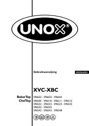
10.1 DRAUGHT DIVERTER STACK ASSEMBLY DIAGRAM<br />
7<br />
6<br />
N.B: application to be effected for discharging fumes on type “B” appliances.<br />
5<br />
1<br />
3<br />
2<br />
4