KwikDial UG ESF w/ labels (b)
KwikDial UG ESF w/ labels (b)
KwikDial UG ESF w/ labels (b)

You also want an ePaper? Increase the reach of your titles
YUMPU automatically turns print PDFs into web optimized ePapers that Google loves.
4<br />
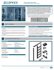
Controller Installation<br />
Installing the Cabinet<br />
1. For safe, reliable operation, select an installation site<br />
which can ideally provide the following conditions:<br />
• For Indoor model controllers – Inside a garage or<br />
other structure which will provide protection from the<br />
weather.<br />
• For outdoor model controllers – Protection from<br />
irrigation spray, wind and snow. A shaded location is<br />
recommended.<br />
• Access to a grounded AC power source (within 4'<br />
[1.2 m] for indoor models) which is not controlled by<br />
a light switch or utilized by a high current load<br />
appliance, such as a refrigerator or air conditioner.<br />
• Access to the sprinkler control valve wiring and<br />
optional accessory wiring.<br />
2. Drive a wood screw (provided) into the wall at eye<br />
level (A). Leave the screw extended approximately 1 ⁄4"<br />
(6 mm) from the wall. See Figure 1.<br />
Note: If installing the controller on drywall or<br />
masonry, install screw anchors. Install the lower<br />
screw anchor 51 ⁄4" (133 mm) directly below the top<br />
screw anchor.<br />
3. Remove the lower cabinet access cover by squeezing<br />
it in on the sides and pulling it directly outward from<br />
the cabinet.<br />
4. Hang the cabinet on the screw using the keyhole slot<br />
on the back panel (B). Make sure the cabinet slides<br />
down securely on the screw.<br />
5. Install the lower mounting screw and tighten securely.<br />
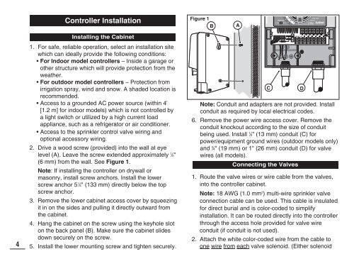
Figure 1<br />
B<br />
A<br />
Note: Conduit and adapters are not provided. Install<br />
conduit as required by local electrical codes.<br />
6. Remove the power wire access cover. Remove the<br />
conduit knockout according to the size of conduit<br />
being used. Install 1 ⁄2" (13 mm) conduit (C) for<br />
power/equipment ground wires (outdoor models only)<br />
and 3 ⁄4" (19 mm) or 1" (26 mm) conduit (D) for valve<br />
wires (all models).<br />
Connecting the Valves<br />
1. Route the valve wires or wire cable from the valves,<br />
into the controller cabinet.<br />
Note: 18 AWG (1.0 mm2 ) multi-wire sprinkler valve<br />
connection cable can be used. This cable is insulated<br />
for direct burial and is color-coded to simplify<br />
installation. It can be routed directly into the controller<br />
through the access hole provided for valve wire<br />
conduit (if conduit is not used).<br />
2. Attach the white color-coded wire from the cable to<br />
one wire from each valve solenoid. (Either solenoid<br />
C<br />
D