

3NJ62 Switch Disconnectors with Fuses
3NJ62 Switch Disconnectors with Fuses
3NJ62 Switch Disconnectors with Fuses

Create successful ePaper yourself
Turn your PDF publications into a flip-book with our unique Google optimized e-Paper software.
SENTRON<br />
© Siemens AG 2008<br />
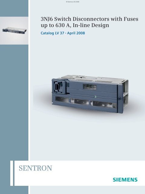
3NJ6 <strong>Switch</strong> <strong>Disconnectors</strong> <strong>with</strong> <strong>Fuses</strong><br />
up to 630 A, In-line Design<br />
Catalog LV 37 • April 2008
Low-Voltage Controls and<br />
Distribution<br />
SIRIUS · SENTRON · SIVACON<br />
Order No.:<br />
Catalog<br />
E86060-K1002-A101-A7-7600<br />
Technical Information incl.<br />
Low-Voltage<br />
Controls and Components<br />
for Applications according to UL<br />
Order no.:<br />
E86060-K1816-A101-A1-7600<br />
Industrial Communication<br />
Industrial Communication<br />
for Automation and Drives<br />
Order No.:<br />
E86060-K6710-A101-B6-7600<br />
E86060-K6710-A121-A2-7600<br />
SICUBE<br />
System Cubicles and<br />
Cubicle Air-Conditioning<br />
Order No.:<br />
E86060-K1920-A101-A3-7600<br />
SIDAC<br />
Reactors and Filters<br />
Order No.:<br />
E86060-K2803-A101-A4-7600<br />
SIVACON 8PS<br />
CD-K, BD01, BD2<br />
Busbar Trunking Systems<br />
up to 1250 A<br />
Order No.:<br />
E86060-K1870-A101-A3-7600<br />
Automation & Drives<br />
The A&D Offline Mall<br />
CD-ROM:<br />
E86060-D4001-A110-C6-7600<br />
DVD:<br />
E86060-D4001-A510-C6-7600<br />
A&D Mall<br />
Internet:<br />
http://www.siemens.com/<br />
automation/mall<br />
Catalog-PDF<br />
Internet:<br />
http://www.automation.<br />
siemens.com/cd<br />
LV 1<br />
LV 1 T<br />
Systems · Controlgear: Contactors and contactor assemblies,<br />
solid-state switching devices · Protection equipment · Load<br />
feeders, motor starters and soft starters · Monitoring and control<br />
devices · Detecting devices · Commanding and signaling<br />
devices · Transformers · Power supplies · Planning and configuration<br />
<strong>with</strong> SIRIUS · Power Management System · SIVACON<br />
Power, distribution boards, busway and cubicle systems ·<br />
SENTRON switching and protection devices for power distribution<br />
· Air circuit breakers, molded case circuit breakers, switch<br />
disconnectors · Software for power distribution· BETA low-voltage<br />
circuit protection<br />
LV 16 SIRIUS 3RV17 and 3RV18 circuit breakers according to UL 489<br />
· SIVACON Components for 8US Distribution Systems according<br />
to UL 508A · SENTRON 3WL5 air circuit breakers/non-automatic<br />
air circuit breakers according to UL 489/IEC · SENTRON<br />
3VL Molded Case Circuit Breakers according to UL 489/IEC ·<br />
ALPHA Devices according to UL Standard ·<br />
BETA Devices according to UL standard<br />
IK PI<br />
IK PI N<br />
PROFINET/Industrial Ethernet · Industrial Mobile<br />
Communicaton · PROFIBUS to IEC 61158/EN 50170 · SIMATIC<br />
ET 200 distributed I/Os · AS-Interface to EN 50295/IEC 61158 ·<br />
Remote operation <strong>with</strong> SINAUT Telecontrol · Routers ·<br />
ECOFAST system<br />
LV 50 System cubicles · Cubicle modifications · Cubicle expansion<br />
components · Accessories · Special cubicles<br />
Cubicle solutions in applications · Cubicle air-conditioning ·<br />
Special colors<br />
LV 60 Commutating reactors for converters · Mains reactors for frequency<br />
converters · Iron-core output reactors ·<br />
Ferrite output reactors · Iron-core smoothing reactors · Smoothing<br />
air-core reactors · Filter reactors · Application-specific<br />
reactors · Radio interference suppression filters · dv/dt filters ·<br />
Sinewave filters<br />
LV 70 Busbar trunking systems, overview · CD-K system<br />
(25 A to 40 A) · BD01 system (40 A to 160 A) ·<br />
BD2 system (160 A to 1250 A)<br />
CA 01 All Automation and Drives products,<br />
including those in the catalogs listed above.<br />
All Automation and Drives products,<br />
including those in the catalogs listed above.<br />
Registered trademarks Technical Assistance<br />
All product designations may be registered trademarks or<br />
product names of Siemens AG or other supplying<br />
companies. Third parties using these trademarks or product<br />
names for their own purposes may infringe upon the rights of<br />
the trademark owners.<br />
Further information about low-voltage controls is available on<br />
the Internet at:<br />
http://www.siemens.com/lowvoltage<br />
© Siemens AG 2008<br />
Related catalogs Contents<br />
All catalogs for low-voltage controls and distribution can be downloaded<br />
as PDF files.<br />
Expert technical assistance for<br />
Low-voltage controls and<br />
electrical installation.<br />
Tel.: +49 (9 11) 8 95-59 00<br />
Fax: +49 (9 11) 8 95-59 07<br />
E-Mail: technicalassistance@siemens.com
SENTRON<br />
3NJ6 In-Line <strong>Switch</strong><br />
<strong>Disconnectors</strong><br />
<strong>with</strong> <strong>Fuses</strong> up to 630 A<br />
Catalog LV 37 · 04/2008<br />
Replaces:<br />
Catalog LV 37 · 01/2008<br />
The products in this catalog can also be found<br />
in the electronic catalog CA 01.<br />
Order No.:<br />
E86060-D4001-A110-C6-7600 (CD-ROM)<br />
E86060-D4001-A510-C6-7600 (DVD)<br />
Contact your local Siemens<br />
representative for further information<br />
© Siemens AG 2008<br />
© Siemens AG 2008<br />
Introduction 1<br />
<strong>3NJ62</strong> <strong>Switch</strong> <strong>Disconnectors</strong> <strong>with</strong> <strong>Fuses</strong><br />
up to 630 A<br />
3NJ61 <strong>Switch</strong> <strong>Disconnectors</strong> <strong>with</strong> <strong>Fuses</strong><br />
up to 630 A<br />
2<br />
3<br />
Appendix 4
Explanations<br />
■ General information<br />
Things you should know about Catalog LV 37 · 04/2008<br />
Delivery times (DT)<br />
} Preferred type<br />
A 2 working days<br />
B 1 week<br />
C 3 weeks<br />
D 6 week<br />
X on request<br />
Price units (PU)<br />
2<br />
Catalog LV 37 01/2008 contains selection- and<br />
ordering relevant data for the products mentioned in<br />
the catalog. In the "Catalog" section, the following<br />
topics can be found: "Overview", "Benefits", "Application",<br />
"Selection and ordering data", "Options "<br />
and "Accessories".<br />
Preferred types are available immediately from<br />
stock, i.e. are dispatched <strong>with</strong>in 24 hours.<br />
Normal quantities of the products are usually delivred<br />
<strong>with</strong>in the specified time following receipt of<br />
your order at our branch.<br />
In exceptional cases, the actual delivery period<br />
may differ from that specified.<br />
The price unit defines the number of units, sets or<br />
meters to which the specified price and weight<br />
apply.<br />
Packaging sizes (PS)<br />
Price groups (PG)<br />
Weight<br />
Dimensions<br />
The packaging size defines the number, e.g. of<br />
units, sets or meters, for outer packaging.<br />
Only the quantity defined by the packaging size or<br />
a multiple thereof can be ordered!<br />
Each product is assigned to a price group.<br />
The defined weight in kg refers to the price unit<br />
(PU).<br />
All dimensions in mm..<br />
Siemens LV 37 · 04/2008<br />
© Siemens AG 2008<br />
If required, the topics "Design", "Function", "Configuration", "Technical specifications",<br />
"Characteristic curves", "Dimensional drawings", "Schematics" and<br />
"More information" can be found in the "Technical Information" section.<br />
The delivery periods apply up to the ramp at Siemens AG (products ready for<br />
dispatch). The transport times depend on the destination and type of shipping.<br />
The standard transport time for Germany is 1 day.<br />
The delivery times specified here represent the state of 10/2007. They are permanently<br />
optimized. Up-to-date information can be found at<br />
http://www.siemens.com/automation/mall.<br />
For multi-unit packing and reusable packaging see Appendix.
Introduction<br />
© Siemens AG 2008<br />
1/2 Answers for Industry.<br />
1/4 Low-Voltage Controls and<br />
Distribution. The basis for<br />
progressive solutions.<br />
Siemens LV 37 · 04/2008<br />
1
1/2<br />
Siemens LV 37 · 04/2008<br />
© Siemens AG 2008
Siemens offers automation, drive, and<br />
low-voltage switching technology as well<br />
as industrial software from standard<br />
products up to entire industry solutions.<br />
The industry software enables our industry<br />
customers to optimize the entire value<br />
chain – from product design and development<br />
through manufacture and sales up<br />
to after-sales service. Our electrical and<br />
mechanical components offer integrated<br />
technologies for the entire drive train –<br />
from couplings to gear units, from motors<br />
to control and drive solutions for all<br />
engineering industries. Our technology<br />
platform TIP offers robust solutions for<br />
power distribution.<br />
© Siemens AG 2008<br />
Answers for Industry.<br />
Siemens Industry answers the challenges in the manufacturing<br />
and the process industry as well as in the building automation<br />
business. Our drive and automation solutions based on<br />
Totally Integrated Automation (TIA) and Totally Integrated Power (TIP)<br />
are employed in all kinds of industry. In the manufacturing and the<br />
process industry. In industrial as well as in functional buildings.<br />
The high quality of our products<br />
sets industry-wide benchmarks.<br />
High environmental aims are part of<br />
our eco-management, and we implement<br />
these aims consistently. Right from<br />
product design, possible effects on<br />
the environment are examined. Hence<br />
many of our products and systems are<br />
RoHS compliant (Restriction of Hazardous<br />
Substances). As a matter of course, our<br />
production sites are certified according<br />
to DIN EN ISO 14001, but to us,<br />
environmental protection also means<br />
most efficient utilization of valuable<br />
resources. The best example are our<br />
energy-efficient drives <strong>with</strong> energy savings<br />
up to 60 %.<br />
Check out the opportunities our<br />
automation and drive solutions provide.<br />
And discover how you can sustainably<br />
enhance your competitive edge <strong>with</strong> us.<br />
Siemens LV 37 · 04/2008<br />
1/3
Low-Voltage Controls and Distribution.<br />
The basis for progressive solutions.<br />
Extremely high demands are made on<br />
modern low-voltage controls and distribution:<br />
users want cost-effective solutions that are<br />
easy to integrate in control cabinets, distribu-<br />
tion boards and distributed systems and can<br />
communicate perfectly <strong>with</strong> each other.<br />
Siemens has the answer: SIRIUS industrial<br />
controls and low-voltage power distribution<br />
<strong>with</strong> Power Management, SIVACON and<br />
SENTRON.<br />
SIRIUS industrial controls<br />
The SIRIUS range has everything you need for switching,<br />
protecting and starting loads. Products for monitoring,<br />
control, detection, commanding, signaling and<br />
power supply round off the spectrum of industrial<br />
controls.<br />
Combined <strong>with</strong> Totally Integrated Automation, Safety<br />
Integrated and ECOFAST, our product portfolio can be<br />
bundled to create optimized systems. All in all, Siemens<br />
provides innovative controls <strong>with</strong> modern features,<br />
such as integrated communication and safety technology<br />
that work to your advantage: The basis for groundbreaking<br />
integrated solutions.<br />
1/4<br />
Siemens LV 37 · 04/2008<br />
© Siemens AG 2008
SIRIUS<br />
SENTRON<br />
SIVACON<br />
© Siemens AG 2008<br />
Low-voltage power distribution <strong>with</strong> Power Management,<br />
SIVACON and SENTRON<br />
Non-residental buildings and industrial plants have one thing in<br />
common: <strong>with</strong>out electricity, everything comes to a halt. The<br />
availability, safety and cost effectiveness of the power distribution<br />
system is of utmost importance – from the medium voltage<br />
supply point through to the socket outlet. And only integrated<br />
solutions can ensure maximum efficiency for planning, configuration<br />
and operation.<br />
The concept is called Totally Integrated Power from Siemens.<br />
Total integration in planning and configuration creates synergies<br />
and saves costs. Perfectly matched products and systems<br />
provide efficient engineering and reliable operation.<br />
Siemens LV 37 · 04/2008<br />
1/5
Notes<br />
1/6<br />
Siemens LV 37 · 04/2008<br />
© Siemens AG 2008
© Siemens AG 2008<br />
<strong>3NJ62</strong> <strong>Switch</strong> <strong>Disconnectors</strong><br />
<strong>with</strong> <strong>Fuses</strong><br />
Catalog<br />
Technical Information<br />
Introduction<br />
2/2 - Overview<br />
2/3 - Benefits<br />
2/3 - Application<br />
For LV HRC fuse links<br />
2/4 - Selection and ordering data<br />
2/5 - Options<br />
2/12 - Accessories<br />
General data<br />
2/19 - Design<br />
2/21 - Function<br />
2/22 - Configuration<br />
2/25 - Technical specifications<br />
2/26 - Dimensional drawings<br />
2/28 - Schematics<br />
For LV HRC fuses, see<br />
LV 1 · 2008, Chapter 19<br />
"BETA Low-Voltage<br />
Circuit Protection"<br />
Siemens LV 37 · 04/2008<br />
2
2<br />
<strong>3NJ62</strong> <strong>Switch</strong> <strong>Disconnectors</strong> <strong>with</strong> <strong>Fuses</strong><br />
Introduction<br />
■ Overview<br />
<strong>3NJ62</strong> switch disconnector <strong>with</strong> fuses<br />
Overview of components and accessory parts<br />
1<br />
2<br />
3<br />
4<br />
5<br />
6<br />
7<br />
8<br />
9<br />
2/2<br />
<br />
<br />
<br />
<br />
<br />
<br />
Siemens LV 37 · 04/2008<br />
<br />
<br />
<strong>3NJ62</strong> switch disconnector basic device<br />
her in size 00, open, <strong>with</strong>out front panel<br />
Guide rails<br />
Cover for empty sections<br />
Connection module<br />
Busbar cover<br />
Contact extension<br />
Current transformer<br />
Current transformer busbar<br />
Terminals<br />
<br />
<br />
<br />
<br />
© Siemens AG 2008<br />
All key product features at a glance<br />
Type-tested according to IEC EN 60947-3<br />
Voltage levels up to 690 V AC<br />
160 to 630 A for LV HRC fuse links,<br />
according to IEC 60269-1/EN 60269-1<br />
3-pole versions available<br />
185 mm phase center distance of plug-in contacts<br />
Developed for switchgears in plug-in design<br />
Horizontal or vertical mounting position<br />
Front panel locked in ON position<br />
Degree of protection IP41<br />
<br />
10 Stud terminal<br />
11 Terminal cover<br />
12 Auxiliary switch<br />
13 Holder for measuring instruments<br />
14 Multi-function plug<br />
15 Moving-iron measuring instrument<br />
16 Bi-metal measuring instrument<br />
17 LV HRC fuse links<br />
18 BS fuse links<br />
<br />
<br />
<br />
<br />
<br />
NSE0_01917
© Siemens AG 2008<br />
<strong>3NJ62</strong> <strong>Switch</strong> <strong>Disconnectors</strong> <strong>with</strong> <strong>Fuses</strong><br />
Siemens LV 37 · 04/2008<br />
Introduction<br />
■ Benefits<br />
■ Application<br />
Key advantages for switchgear manufacturers due to the The plug-in 3NJ6 switch disconnectors <strong>with</strong> fuses are installed<br />
following:<br />
in low-voltage distribution boards where a minimum amount of<br />
Compact, modular design<br />
Simple and efficient mounting due to incoming plug-in contact<br />
space is available for a maximum number of cable ducts to the<br />
power distribution. They can be easily fitted in all common control<br />
cabinets (minimum depth: 400 mm).<br />
High packing density in the field<br />
Cable connection <strong>with</strong> cable clamps or cable lugs<br />
The plug-in <strong>3NJ62</strong> switch disconnectors <strong>with</strong> fuses are available<br />
for rated uninterrupted currents of 160 to 630 A. LV HRC fuse<br />
Can be mounted in different control cabinet depths<br />
Comprehensive range of accessories<br />
links according to IEC 60269-1/EN 60269-1 (sizes LV HRC 00 to<br />
LV HRC 3) provide overload and short-circuit protection up to<br />
690 V AC.<br />
The advantages for users are:<br />
The switch disconnectors can be retrofitted at any time <strong>with</strong><br />
Conversion, retrofitting and replacement <strong>with</strong>out switching off auxiliary switches, an ammeter (48 x 48 mm) and current<br />
the switchgear<br />
transformers, <strong>with</strong> no extra space required. For installation in<br />
Dead-state fuse replacement<br />
Maintenance free<br />
control cabinets of > 400 mm depth, the mounting depth of the<br />
disconnectors can be increased by 200 mm using a contact<br />
extension. Further installation accessories, such as guide rails<br />
High personal safety<br />
Operating handle can be locked in OFF position<br />
Clear and unambiguous switch position indicator<br />
and blanking covers, complete the product range.<br />
2/3<br />
2
2<br />
<strong>3NJ62</strong> <strong>Switch</strong> <strong>Disconnectors</strong> <strong>with</strong> <strong>Fuses</strong><br />
For LV HRC fuse links<br />
■ Selection and ordering data<br />
2/4<br />
Size Rated uninterrupted<br />
current<br />
I u<br />
at 500 V AC<br />
Siemens LV 37 · 04/2008<br />
For fuse links<br />
according to<br />
DIN 43620<br />
© Siemens AG 2008<br />
DT Order No. Price<br />
per PU<br />
PU<br />
(UNIT,<br />
M)<br />
PS* PG Weight<br />
per PU<br />
approx.<br />
A<br />
3-pole, standard switching capacity S<br />
Manually operated<br />
Type kg<br />
00 160 00/000 } <strong>3NJ62</strong> 03-1AA0@-@@@@ 1 unit 143 3.630<br />
1 250 1 } <strong>3NJ62</strong> 13-1AA0@-@@@@ 1 unit 143 6.750<br />
2 400 2/1 } <strong>3NJ62</strong> 23-1AA0@-@@@@ 1 unit 143 15.000<br />
3 630 3/2 } <strong>3NJ62</strong> 33-1AA0@-@@@@ 1 unit 143 15.360<br />
3-pole, high switching capacity H<br />
Manually operated<br />
00 160 00/000 } <strong>3NJ62</strong> 03-3AA0@-@@@@ 1 unit 143 3.630<br />
1 250 1 } <strong>3NJ62</strong> 13-3AA0@-@@@@ 1 unit 143 6.750<br />
2 400 2/1 } <strong>3NJ62</strong> 23-3AA0@-@@@@ 1 unit 143 15.000<br />
3 630 3/2 } <strong>3NJ62</strong> 33-3AA0@-@@@@ 1 unit 143 15.360<br />
Order No. supplement Additional<br />
price<br />
Standard Order No. supplement<br />
(for other Order No. supplements see next page)<br />
Without auxiliary switches, ammeters, current transformers }<br />
0 0AA0<br />
--<br />
* You can order this quantity or a multiple thereof.
■ Options<br />
1 st Order No. supplement:<br />
Auxiliary switch wired to multi-function plug<br />
<strong>3NJ62</strong> <strong>Switch</strong> <strong>Disconnectors</strong> <strong>with</strong> <strong>Fuses</strong><br />
DT Order No. supplement<br />
<strong>3NJ62</strong> ..-....@-....<br />
None } 0<br />
1 NO B 1<br />
1 NC B 2<br />
1 NO + 1 NC B 3<br />
2nd Order No. supplement:<br />
Ammeter and current transformer wired<br />
Ammeters Current transformers<br />
Primary current Secondary current Accuracy class<br />
For size LV HRC 00<br />
A A<br />
DT Order No. supplement<br />
<strong>3NJ62</strong> ..-.....-@@@@<br />
None None None None } 0AA0<br />
1 current transformer to 1 ammeter<br />
Moving iron 50 1 1 B 1DB1<br />
Moving iron 50 5 1 B 1DB4<br />
Moving iron 100 1 1 B 1DD1<br />
Moving iron 100 5 1 B 1DD4<br />
Moving iron 150 1 1 B 1DE1<br />
Moving iron 150 5 1 B 1DE4<br />
Bi-metal 50 1 1 B 2DB1<br />
Bi-metal 50 5 1 B 2DB4<br />
Bi-metal 100 1 1 B 2DD1<br />
Bi-metal 100 5 1 B 2DD4<br />
Bi-metal 150 1 1 B 2DE1<br />
Bi-metal 150 5 1 B 2DE4<br />
1 current transformer to multi-function plug<br />
None 50 1 1 B 0BB1<br />
None 50 5 1 B 0BB4<br />
None 100 1 1 B 0BD1<br />
None 100 1 0.5 B 0BD2<br />
None 100 5 1 B 0BD4<br />
None 100 5 0.5 B 0BD5<br />
None 150 1 1 B 0BE1<br />
None 150 1 0.5 B 0BE2<br />
None 150 5 1 B 0BE4<br />
None 150 5 0.5 B 0BE5<br />
3 current transformers to multi-function plug<br />
None 50 1 1 B 0CB1<br />
None 50 5 1 B 0CB4<br />
None 100 1 1 B 0CD1<br />
None 100 1 0.5 B 0CD2<br />
None 100 5 1 B 0CD4<br />
None 100 5 0.5 B 0CD5<br />
None 150 1 1 B 0CE1<br />
None 150 1 0.5 B 0CE2<br />
None 150 5 1 B 0CE4<br />
None 150 5 0.5 B 0CE5<br />
* You can order this quantity or a multiple thereof.<br />
© Siemens AG 2008<br />
For LV HRC fuse links<br />
Siemens LV 37 · 04/2008<br />
Additional price<br />
Additional price<br />
2/5<br />
2
2<br />
<strong>3NJ62</strong> <strong>Switch</strong> <strong>Disconnectors</strong> <strong>with</strong> <strong>Fuses</strong><br />
For LV HRC fuse links<br />
2 nd Order No. supplement:<br />
Ammeter and current transformer wired<br />
2/6<br />
Ammeters Current transformers<br />
Primary current Secondary current Accuracy class<br />
Siemens LV 37 · 04/2008<br />
A A<br />
© Siemens AG 2008<br />
1 current transformer to 1 ammeter and multi-function plug<br />
Moving iron 50 1 1 B 1EB1<br />
Moving iron 50 5 1 B 1EB4<br />
Moving iron 100 1 1 B 1ED1<br />
Moving iron 100 1 0.5 B 1ED2<br />
Moving iron 100 5 1 B 1ED4<br />
Moving iron 100 5 0.5 B 1ED5<br />
Moving iron 150 1 1 B 1EE1<br />
Moving iron 150 1 0.5 B 1EE2<br />
Moving iron 150 5 1 B 1EE4<br />
Moving iron 150 5 0.5 B 1EE5<br />
Bi-metal 50 1 1 B 2EB1<br />
Bi-metal 50 5 1 B 2EB4<br />
Bi-metal 100 1 1 B 2ED1<br />
Bi-metal 100 1 0.5 B 2ED2<br />
Bi-metal 100 5 1 B 2ED4<br />
Bi-metal 100 5 0.5 B 2ED5<br />
Bi-metal 150 1 1 B 2EE1<br />
Bi-metal 150 1 0.5 B 2EE2<br />
Bi-metal 150 5 1 B 2EE4<br />
Bi-metal 150 5 0.5 B 2EE5<br />
3 current transformers to 1 ammeter and multi-function plug<br />
DT Order No. supplement<br />
<strong>3NJ62</strong> ..-.....-@@@@<br />
Moving iron 50 1 1 B 1FB1<br />
Moving iron 50 5 1 B 1FB4<br />
Moving iron 100 1 1 B 1FD1<br />
Moving iron 100 1 0.5 B 1FD2<br />
Moving iron 100 5 1 B 1FD4<br />
Moving iron 100 5 0.5 B 1FD5<br />
Moving iron 150 1 1 B 1FE1<br />
Moving iron 150 5 0.5 B 1FE2<br />
Moving iron 150 5 1 B 1FE4<br />
Moving iron 150 5 0.5 B 1FE5<br />
Bi-metal 50 1 1 B 2FB1<br />
Bi-metal 50 5 1 B 2FB4<br />
Bi-metal 100 1 1 B 2FD1<br />
Bi-metal 100 1 0.5 B 2FD2<br />
Bi-metal 100 5 1 B 2FD4<br />
Bi-metal 100 5 0.5 B 2FD5<br />
Bi-metal 150 1 1 B 2FE1<br />
Bi-metal 150 1 0.5 B 2FE2<br />
Bi-metal 150 5 1 B 2FE4<br />
Bi-metal 150 5 0.5 B 2FE5<br />
Additional price<br />
* You can order this quantity or a multiple thereof.
© Siemens AG 2008<br />
<strong>3NJ62</strong> <strong>Switch</strong> <strong>Disconnectors</strong> <strong>with</strong> <strong>Fuses</strong><br />
Ammeters Current transformers<br />
Primary current Secondary current Accuracy class<br />
DT Order No. supplement<br />
<strong>3NJ62</strong> ..-.....-@@@@<br />
For LV HRC fuse links<br />
A A<br />
For size LV HRC 1<br />
None None None None } 0AA0<br />
1 current transformer to 1 ammeter<br />
Moving iron 50 1 1 B 1DB1<br />
Moving iron 50 5 1 B 1DB4<br />
Moving iron 100 1 1 B 1DD1<br />
Moving iron 100 5 1 B 1DD4<br />
Moving iron 150 1 1 B 1DE1<br />
Moving iron 150 5 1 B 1DE4<br />
Moving iron 200 1 1 B 1DF1<br />
Moving iron 200 5 1 B 1DF4<br />
Moving iron 250 1 1 B 1DG<br />
Moving iron 250 5 1 B 1DG4<br />
Bi-metal 50 1 1 B 2DB1<br />
Bi-metal 50 5 1 B 2DB4<br />
Bi-metal 100 1 1 B 2DD1<br />
Bi-metal 100 5 1 B 2DD4<br />
Bi-metal 150 1 1 B 2DE1<br />
Bi-metal 150 5 1 B 2DE4<br />
Bi-metal 200 1 1 B 2DF1<br />
Bi-metal 200 5 1 B 2DF4<br />
Bi-metal 250 1 1 B 2DG1<br />
Bi-metal 250 5 1 B 2DG4<br />
1 current transformer to multi-function plug<br />
None 50 1 1 B 0BB1<br />
None 50 5 1 B 0BB4<br />
None 100 1 1 B 0BD1<br />
None 100 1 0.5 B 0BD2<br />
None 100 5 1 B 0BD4<br />
None 100 5 0.5 B 0BD5<br />
None 150 1 1 B 0BE1<br />
None 150 1 0.5 B 0BE2<br />
None 150 5 1 B 0BE4<br />
None 150 5 0.5 B 0BE5<br />
None 200 1 1 B 0BF1<br />
None 200 1 0.5 B 0BF2<br />
None 200 5 1 B 0BF4<br />
None 200 5 0.5 B 0BF5<br />
None 250 1 1 B 0BG1<br />
None 250 1 0.5 B 0BG2<br />
None 250 5 1 B 0BG4<br />
None 250 5 0.5 B 0BG5<br />
3 current transformers to multi-function plug<br />
None 50 1 1 B 0CB1<br />
None 50 5 1 B 0CB4<br />
None 100 1 1 B 0CD1<br />
None 100 1 0.5 B 0CD 2<br />
None 100 5 1 B 0CD4<br />
None 100 5 0.5 B 0CD5<br />
None 150 1 1 B 0CE1<br />
None 150 1 0.5 B 0CE2<br />
None 150 5 1 B 0CE4<br />
None 150 5 0.5 B 0CE5<br />
None 200 1 1 B 0CF1<br />
None 200 1 0.5 B 0CF2<br />
None 200 5 1 B 0CF4<br />
None 200 5 0.5 B 0CF5<br />
None 250 1 1 B 0CG1<br />
None 250 1 0.5 B 0CG2<br />
None 250 5 1 B 0CG4<br />
None 250 5 0.5 B 0CG5<br />
1 current transformer to 1 ammeter and multi-function plug<br />
Moving iron<br />
Moving iron<br />
50<br />
50<br />
1<br />
5<br />
1<br />
B<br />
1EB1<br />
1EB4<br />
Moving iron<br />
Moving iron<br />
100<br />
100<br />
1<br />
1<br />
0.5<br />
B<br />
1ED1<br />
1ED2<br />
Moving iron 100 5 1 B 1ED4<br />
Moving iron 100 5 0.5 B 1ED5<br />
Moving iron<br />
Moving iron<br />
150<br />
150<br />
1<br />
1<br />
0.5<br />
B<br />
1EE1<br />
1EE2<br />
Moving iron 150 5 1 B 1EE4<br />
Moving iron 150 5 0.5 B 1EE5<br />
* You can order this quantity or a multiple thereof.<br />
Siemens LV 37 · 04/2008<br />
Additional price<br />
2/7<br />
2
2<br />
<strong>3NJ62</strong> <strong>Switch</strong> <strong>Disconnectors</strong> <strong>with</strong> <strong>Fuses</strong><br />
For LV HRC fuse links<br />
2/8<br />
Ammeters Current transformers<br />
Primary current Secondary current Accuracy class<br />
Siemens LV 37 · 04/2008<br />
© Siemens AG 2008<br />
DT Order No. supplement<br />
<strong>3NJ62</strong> ..-.....-@@@@<br />
A A<br />
Moving iron 200 1 1 B 1EF1<br />
Moving iron 200 1 0.5 B 1EF2<br />
Moving iron 200 5 1 B 1EF4<br />
Moving iron 200 5 0.5 B 1EF5<br />
Moving iron 250 1 1 B 1EG1<br />
Moving iron 250 1 0.5 B 1EG2<br />
Moving iron 250 5 1 B 1EG4<br />
Moving iron 250 5 0.5 B 1EG5<br />
Bi-metal 50 1 1 B 2EB1<br />
Bi-metal 50 5 1 B 2EB4<br />
Bi-metal 100 1 1 B 2ED1<br />
Bi-metal 100 1 0.5 B 2ED2<br />
Bi-metal 100 5 1 B 2ED4<br />
Bi-metal 100 5 0.5 B 2ED5<br />
Bi-metal 150 1 1 B 2EE1<br />
Bi-metal 150 1 0.5 B 2EE2<br />
Bi-metal 150 5 1 B 2EE4<br />
Bi-metal 150 5 0.5 B 2EE5<br />
Bi-metal 200 1 1 B 2EF1<br />
Bi-metal 200 1 0.5 B 2EF2<br />
Bi-metal 200 5 1 B 2EF4<br />
Bi-metal 200 5 0.5 B 2EF5<br />
Bi-metal 250 1 1 B 2EG1<br />
Bi-metal 250 1 0.5 B 2EG2<br />
Bi-metal 250 5 1 B 2EG4<br />
Bi-metal 250 5 0.5 B 2EG5<br />
3 current transformers to 1 ammeter and multi-function plug<br />
Moving iron 50 1 1 B 1FB1<br />
Moving iron 50 5 1 B 1FB4<br />
Moving iron 100 1 1 B 1FD1<br />
Moving iron 100 1 0.5 B 1FD2<br />
Moving iron 100 5 1 B 1FD4<br />
Moving iron 100 5 0.5 B 1FD5<br />
Moving iron 150 1 1 B 1FE1<br />
Moving iron 150 1 0.5 B 1FE2<br />
Moving iron 150 5 1 B 1FE4<br />
Moving iron 150 5 0.5 B 1FE5<br />
Moving iron 200 1 1 B 1FF1<br />
Moving iron 200 1 0.5 B 1FF2<br />
Moving iron 200 5 1 B 1FF4<br />
Moving iron 200 5 0.5 B 1FF5<br />
Moving iron 250 1 1 B 1FG1<br />
Moving iron 250 1 0.5 B 1FG2<br />
Moving iron 250 5 1 B 1FG4<br />
Moving iron 250 5 0.5 B 1FG5<br />
Bi-metal 50 1 1 B 2FB1<br />
Bi-metal 50 5 1 B 2FB4<br />
Bi-metal 100 1 1 B 2FD1<br />
Bi-metal 100 1 0.5 B 2FD2<br />
Bi-metal 100 5 1 B 2FD4<br />
Bi-metal 100 5 0.5 B 2FD5<br />
Bi-metal 150 1 1 B 2FE1<br />
Bi-metal 150 1 0.5 B 2FE2<br />
Bi-metal 150 5 1 B 2FE4<br />
Bi-metal 150 5 0.5 B 2FE5<br />
Bi-metal 200 1 1 B 2FF1<br />
Bi-metal 200 1 0.5 B 2FF2<br />
Bi-metal 200 5 1 B 2FF4<br />
Bi-metal 200 5 0.5 B 2FF5<br />
Bi-metal 250 1 1 B 2FG1<br />
Bi-metal 250 1 0.5 B 2FG2<br />
Bi-metal 250 5 1 B 2FG4<br />
Bi-metal 250 5 0.5 B 2FG5<br />
Additional price<br />
* You can order this quantity or a multiple thereof.
For size LV HRC 2<br />
<strong>3NJ62</strong> <strong>Switch</strong> <strong>Disconnectors</strong> <strong>with</strong> <strong>Fuses</strong><br />
Ammeters Current transformers<br />
Primary current Secondary current Accuracy class<br />
A A<br />
DT Order No. supplement<br />
<strong>3NJ62</strong> ..-.....-@@@@<br />
None None None None } 0AA0<br />
1 current transformer to 1 ammeter<br />
Moving iron 300 1 1 B 1DH1<br />
Moving iron 300 5 1 B 1DH4<br />
Moving iron 400 1 1 B 1DJ1<br />
Moving iron 400 5 1 B 1DJ4<br />
Bi-metal 300 1 1 B 2DH1<br />
Bi-metal 300 5 1 B 2DH4<br />
Bi-metal 400 1 1 B 2DJ1<br />
Bi-metal 400 5 1 B 2DJ4<br />
1 current transformer to multi-function plug<br />
None 300 1 1 B 0BH1<br />
None 300 1 0.5 B 0BH2<br />
None 300 5 1 B 0BH4<br />
None 300 5 0.5 B 0BH5<br />
None 400 1 1 B 0BJ1<br />
None 400 1 0.5 B 0BJ2<br />
None 400 5 1 B 0BJ4<br />
None 400 5 0.5 B 0BJ5<br />
3 current transformers to multi-function plug<br />
None 300 1 1 B 0CH1<br />
None 300 1 0.5 B 0CH2<br />
None 300 5 1 B 0CH4<br />
None 300 5 0.5 B 0CH5<br />
None 400 1 1 B 0CJ1<br />
None 400 1 0.5 B 0CJ2<br />
None 400 5 1 B 0CJ4<br />
None 400 5 0.5 B 0CJ5<br />
1 current transformer to 1 ammeter and multi-function plug<br />
Moving iron 300 1 1 B 1EH1<br />
Moving iron 300 1 0.5 B 1EH2<br />
Moving iron 300 5 1 B 1EH4<br />
Moving iron 300 5 0.5 B 1EH5<br />
Moving iron 400 1 1 B 1EJ1<br />
Moving iron 400 1 0.5 B 1EJ2<br />
Moving iron 400 5 1 B 1EJ4<br />
Moving iron 400 5 0.5 B 1EJ5<br />
Bi-metal 300 1 1 B 2EH1<br />
Bi-metal 300 1 0.5 B 2EH2<br />
Bi-metal 300 5 1 B 2EH4<br />
Bi-metal 300 5 0.5 B 2EH5<br />
Bi-metal 400 1 1 B 2EJ1<br />
Bi-metal 400 1 0.5 B 2EJ2<br />
Bi-metal 400 5 1 B 2EJ4<br />
Bi-metal 400 5 0.5 B 2EJ5<br />
3 current transformers to 1 ammeter and multi-function plug<br />
Moving iron 300 1 1 B 1FH1<br />
Moving iron 300 1 0.5 B 1FH2<br />
Moving iron 300 5 1 B 1FH4<br />
Moving iron 300 5 0.5 B 1FH5<br />
Moving iron 400 1 1 B 1FJ1<br />
Moving iron 400 1 0.5 B 1FJ2<br />
Moving iron 400 5 1 B 1FJ4<br />
Moving iron 400 5 0.5 B 1FJ5<br />
Bi-metal 300 1 1 B 2FH1<br />
Bi-metal 300 1 0.5 B 2FH2<br />
Bi-metal 300 5 1 B 2FH4<br />
Bi-metal 300 5 0.5 B 2FH5<br />
Bi-metal 400 1 1 B 2FJ1<br />
Bi-metal 400 1 0.5 B 2FJ2<br />
Bi-metal 400 5 1 B 2FJ4<br />
Bi-metal 400 5 0.5 B 2FJ5<br />
* You can order this quantity or a multiple thereof.<br />
© Siemens AG 2008<br />
For LV HRC fuse links<br />
Siemens LV 37 · 04/2008<br />
Additional price<br />
2/9<br />
2
2<br />
<strong>3NJ62</strong> <strong>Switch</strong> <strong>Disconnectors</strong> <strong>with</strong> <strong>Fuses</strong><br />
For LV HRC fuse links<br />
For size LV HRC 3<br />
2/10<br />
Ammeters Current transformers<br />
Primary current Secondary current Accuracy class<br />
Siemens LV 37 · 04/2008<br />
A A<br />
© Siemens AG 2008<br />
DT Order No. supplement<br />
<strong>3NJ62</strong> ..-.....-@@@@<br />
None None None None } 0AA0<br />
1 current transformer to 1 ammeter<br />
Moving iron 300 1 1 B 1DH1<br />
Moving iron 300 5 1 B 1DH4<br />
Moving iron 400 1 1 B 1DJ1<br />
Moving iron 400 5 1 B 1DJ4<br />
Moving iron 500 1 1 B 1DK1<br />
Moving iron 500 5 1 B 1DK4<br />
Moving iron 600 1 1 B 1DL1<br />
Moving iron 600 5 1 B 1DL4<br />
Bi-metal 300 1 1 B 2DH1<br />
Bi-metal 300 5 1 B 2DH4<br />
Bi-metal 400 1 1 B 2DJ1<br />
Bi-metal 400 5 1 B 2DJ4<br />
Bi-metal 500 1 1 B 2DK1<br />
Bi-metal 500 5 1 B 2DK4<br />
Bi-metal 600 1 1 B 2DL1<br />
Bi-metal 600 5 1 B 2DL4<br />
1 current transformer to multi-function plug<br />
None 300 1 1 B 0BH1<br />
None 300 1 0.5 B 0BH2<br />
None 300 5 1 B 0BH4<br />
None 300 5 0.5 B 0BH5<br />
None 400 1 1 B 0BJ1<br />
None 400 1 0.5 B 0BJ2<br />
None 400 5 1 B 0BJ4<br />
None 400 5 0.5 B 0BJ5<br />
None 500 1 1 B 0BK1<br />
None 500 1 0.5 B 0BK2<br />
None 500 5 1 B 0BK4<br />
None 500 5 0.5 B 0BK5<br />
None 600 1 1 B 0BL1<br />
None 600 1 0.5 B 0BL2<br />
None 600 5 1 B 0BL4<br />
None 600 5 0.5 B 0BL5<br />
3 current transformers to multi-function plug<br />
None 300 1 1 B 0CH1<br />
None 300 1 0.5 B 0CH2<br />
None 300 5 1 B 0CH4<br />
None 300 5 0.5 B 0CH5<br />
None 400 1 1 B 0CJ1<br />
None 400 1 0.5 B 0CJ2<br />
None 400 5 1 B 0CJ4<br />
None 400 5 0.5 B 0CJ5<br />
None 500 1 1 B 0CK1<br />
None 500 1 0.5 B 0CK2<br />
None 500 5 1 B 0CK4<br />
None 500 5 0.5 B 0CK5<br />
None 600 1 1 B 0CL1<br />
None 600 1 0.5 B 0CL2<br />
None 600 5 1 B 0CL4<br />
None 600 5 0.5 B 0CL5<br />
1 current transformer to 1 ammeter and multi-function plug<br />
Moving iron 300 1 1 B 1EH1<br />
Moving iron 300 1 0.5 B 1EH2<br />
Moving iron 300 5 1 B 1EH4<br />
Moving iron 300 5 0.5 B 1EH5<br />
Moving iron 400 1 1 B 1EJ1<br />
Moving iron 400 1 0.5 B 1EJ2<br />
Moving iron 400 5 1 B 1EJ4<br />
Moving iron 400 5 0.5 B 1EJ5<br />
Moving iron 500 1 1 B 1EK1<br />
Moving iron 500 1 0.5 B 1EK2<br />
Moving iron 500 5 1 B 1EK4<br />
Moving iron 500 5 0.5 B 1EK5<br />
Moving iron 600 1 1 B 1EL1<br />
Moving iron 600 1 0.5 B 1EL2<br />
Moving iron 600 5 1 B 1EL4<br />
Moving iron 600 5 0.5 B 1EL5<br />
Additional price<br />
* You can order this quantity or a multiple thereof.
<strong>3NJ62</strong> <strong>Switch</strong> <strong>Disconnectors</strong> <strong>with</strong> <strong>Fuses</strong><br />
Ammeters Current transformers<br />
A A<br />
Primary current Secondary current Accuracy class<br />
DT Order No. supplement<br />
<strong>3NJ62</strong> ..-.....-@@@@<br />
A A<br />
Bi-metal 300 1 1 B 2EH1<br />
Bi-metal 300 1 0.5 B 2EH2<br />
Bi-metal 300 5 1 B 2EH4<br />
Bi-metal 300 5 0.5 B 2EH5<br />
Bi-metal 400 1 1 B 2EJ1<br />
Bi-metal 400 1 0.5 B 2EJ2<br />
Bi-metal 400 5 1 B 2EJ4<br />
Bi-metal 400 5 0.5 B 2EJ5<br />
Bi-metal 500 1 1 B 2EK1<br />
Bi-metal 500 1 0.5 B 2EK2<br />
Bi-metal 500 5 1 B 2EK4<br />
Bi-metal 500 5 0.5 B 2EK5<br />
Bi-metal 600 1 1 B 2EL1<br />
Bi-metal 600 1 0.5 B 2EL2<br />
Bi-metal 600 5 1 B 2EL4<br />
Bi-metal 600 5 0.5 B 2EL5<br />
3 current transformers to 1 ammeter and multi-function plug<br />
Moving iron 300 1 1 B 1FH1<br />
Moving iron 300 1 0.5 B 1FH2<br />
Moving iron 300 5 1 B 1FH4<br />
Moving iron 300 5 0.5 B 1FH5<br />
Moving iron 400 1 1 B 1FJ1<br />
Moving iron 400 1 0.5 B 1FJ2<br />
Moving iron 400 5 1 B 1FJ4<br />
Moving iron 400 5 0.5 B 1FJ5<br />
Moving iron 500 1 1 B 1FK1<br />
Moving iron 500 1 0.5 B 1FK2<br />
Moving iron 500 5 1 B 1FK4<br />
Moving iron 500 5 0.5 B 1FK5<br />
Moving iron 600 1 1 B 1FL1<br />
Moving iron 600 1 0.5 B 1FL2<br />
Moving iron 600 5 1 B 1FL4<br />
Moving iron 600 5 0.5 B 1FL5<br />
Bi-metal 300 1 1 B 2FH1<br />
Bi-metal 300 1 0.5 B 2FH2<br />
Bi-metal 300 5 1 B 2FH4<br />
Bi-metal 300 5 0.5 B 2FH5<br />
Bi-metal 400 1 1 B 2FJ1<br />
Bi-metal 400 1 0.5 B 2FJ2<br />
Bi-metal 400 5 1 B 2FJ4<br />
Bi-metal 400 5 0.5 B 2FJ5<br />
Bi-metal 500 1 1 B 2FK1<br />
Bi-metal 500 1 0.5 B 2FK2<br />
Bi-metal 500 5 1 B 2FK4<br />
Bi-metal 500 5 0.5 B 2FK5<br />
Bi-metal 600 1 1 B 2FL1<br />
Bi-metal 600 1 0.5 B 2FL2<br />
Bi-metal 600 5 1 B 2FL4<br />
Bi-metal 600 5 0.5 B 2FL5<br />
* You can order this quantity or a multiple thereof.<br />
© Siemens AG 2008<br />
For LV HRC fuse links<br />
Siemens LV 37 · 04/2008<br />
Additional price<br />
2/11<br />
2
2<br />
<strong>3NJ62</strong> <strong>Switch</strong> <strong>Disconnectors</strong> <strong>with</strong> <strong>Fuses</strong><br />
For LV HRC fuse links<br />
■ Accessories<br />
Size LV HRC 00<br />
3NJ69 23-1BA00<br />
3NJ69 23-1DA00<br />
3NJ69 23-1EB00<br />
3NJ69 20-2BB00<br />
3NJ69 00-2BC00<br />
3NJ69 20-3BD11<br />
3NJ69 20-3DB00<br />
3NJ69 20-3DC00<br />
3NJ69 20-3DD00<br />
2/12<br />
Terminals<br />
Single terminal for 2-/3-pole devices, 2.5 ... 95 mm 2<br />
Siemens LV 37 · 04/2008<br />
DT Order No. Price<br />
per PU<br />
PU<br />
(UNIT,<br />
M)<br />
PS* PG Weight<br />
per PU<br />
approx.<br />
kg<br />
A 3NJ69 23-1BA00 1 3 units 143 0.210<br />
Terminal covers<br />
For 2-/3-pole devices A 3NJ69 23-1DA00 1 1 unit 143 0.063<br />
Contact extensions<br />
3-pole A 3NJ69 23-1EB00 1 1 unit 143 1.700<br />
Auxiliary switches<br />
© Siemens AG 2008<br />
1 NO contact <strong>with</strong> cover A 3NJ69 20-2BB00<br />
1 NO contact A 3NJ69 00-2BC00<br />
1 NC contact <strong>with</strong> cover A 3NJ69 20-2CB00<br />
1 1 unit 143 0.080<br />
1 1 unit 143 0.020<br />
1 1 unit 143 0.080<br />
1 NC contact A 3NJ69 00-2CC00 1 1 unit 143 0.020<br />
Current transformers<br />
For main devices and contact extensions<br />
∅ = Feed-through opening diameter<br />
50/1 A Class 1 1VA, ∅ 21 mm A 3NJ69 20-3BB11 1 1 unit 143 0.160<br />
50/5 A Class 1<br />
1VA, ∅ 21 mm<br />
A 3NJ69 20-3BB21 1 1 unit 143 0.160<br />
100/1 A Class 1 2.5 VA, ∅ 21 mm A 3NJ69 20-3BD11 1 1 unit 143 0.160<br />
100/1 A Class 0.5 2.5 VA, ∅ 21 mm A 3NJ69 20-3BD12 1 1 unit 143 0.160<br />
100/1 A Class 0.5 calibrated 1.5 VA, ∅ 14 mm A 3NJ69 20-3BD13 1 1 unit 143 0.160<br />
100/5 A Class 1 2.5 VA, ∅ 21 mm<br />
A<br />
3NJ69 20-3BD21 1 1 unit 143 0.160<br />
100/5 A Class 0.5 2.5 VA, ∅ 21 mm A 3NJ69 20-3BD22 1 1 unit 143 0.160<br />
100/5 A Class 0.5 calibrated 1.5 VA, ∅ 14 mm D 3NJ69 20-3BD23 1 1 unit 143 0.160<br />
150/1 A Class 1 2.5 VA, ∅ 21 mm A 3NJ69 20-3BE11 1 1 unit 143 0.170<br />
150/1 A Class 0.5 2.5 VA, ∅ 21 mm A 3NJ69 20-3BE12 1 1 unit 143 0.170<br />
150/1 A Class 0.5 calibrated 2.5 VA, ∅ 14 mm A 3NJ69 20-3BE13 1 1 unit 143 0.170<br />
150/5 A Class 1 2.5 VA, ∅ 21 mm A 3NJ69 20-3BE21 1 1 unit 143 0.170<br />
150/5 A Class 0.5 2.5 VA, ∅ 21 mm A 3NJ69 20-3BE22 1 1 unit 143 0.170<br />
150/5 A Class 0.5 calibrated 2.5 VA, ∅ 14 mm D 3NJ69 20-3BE23 1 1 unit 143 0.170<br />
Current transformer busbars for current transformers <strong>with</strong><br />
feed-through opening ∅ 21 mm<br />
For 1 current transformer A 3NJ69 20-3DB00 1 1 unit 143 0.070<br />
For 3 current transformers A 3NJ69 20-3DC00 1 1 unit 143 0.210<br />
For 4 current transformers 1) A 3NJ69 20-3DD00 1 1 unit 143 0.280<br />
Current transformer busbars for current transformers <strong>with</strong><br />
feed-through opening ∅ 14 mm<br />
For 1 current transformer A 3NJ69 20-3DE00 1 1 unit 143 0.070<br />
For 3 current transformers A 3NJ69 20-3DF00 1 1 unit 143 0.210<br />
For 4 current transformers 1) A 3NJ69 20-3DG00 1 1 unit 143 0.280<br />
1) Not available in combinations <strong>with</strong> multi-function plug<br />
* You can order this quantity or a multiple thereof.
3NJ69 00-4GA00<br />
3NJ69 00-4H...<br />
3NJ69 00-4H...<br />
3NJ69 20-3EB00<br />
3NJ69 20-3ED00<br />
3NJ69 20-3EE00<br />
Holders for ammeters<br />
For sizes 00, 1, 2, 3<br />
<strong>3NJ62</strong> <strong>Switch</strong> <strong>Disconnectors</strong> <strong>with</strong> <strong>Fuses</strong><br />
For LV HRC fuse links<br />
Ammeters<br />
Moving-iron measuring instruments for measuring<br />
input on transformer x/1A <strong>with</strong> double overload<br />
50/1 A 0.6 VA A 3NJ69 00-4HB11 1 1 unit 143 0.100<br />
100/1 A 0.6 VA A 3NJ69 00-4HD11 1 1 unit 143 0.100<br />
150/1 A 0.6 VA A 3NJ69 00-4HE11 1 1 unit 143 0.100<br />
Moving-iron measuring instruments for measuring<br />
input on transformer x/5A <strong>with</strong> double overload<br />
50/1 A 0.6 VA A 3NJ69 00-4HB21 1 1 unit 143 0.100<br />
100/5 A 0.6 VA A 3NJ69 00-4HD21 1 1 unit 143 0.100<br />
150/5 A 0.6 VA A 3NJ69 00-4HE21 1 1 unit 143 0.100<br />
Bi-metal measuring instruments for measuring input<br />
on transformer x/1A <strong>with</strong> 1.2-times the overload<br />
50/1 A 1 VA A 3NJ69 00-4HB12 1 1 unit 143 0.100<br />
100/1 A 1 VA A 3NJ69 00-4HD12 1 1 unit 143 0.100<br />
150/1 A 1 VA A 3NJ69 00-4HE12 1 1 unit 143 0.100<br />
Bi-metal measuring instruments for measuring input<br />
on transformer x/5A <strong>with</strong> 1.2-times the overload<br />
50/1 A 1 VA A 3NJ69 00-4HB22 1 1 unit 143 0.100<br />
100/5 A 1 VA A 3NJ69 00-4HD22 1 1 unit 143 0.100<br />
150/5 A 1 VA A 3NJ69 00-4HE22 1 1 unit 143 0.100<br />
Multi-function plugs<br />
6x2.5mm 2 , <strong>with</strong> fixing screws A 3NJ69 20-3EB00 1 1 unit 143 0.047<br />
8x2.5mm 2 , <strong>with</strong>out fixing screws A 3NJ69 20-3ED00 1 1 unit 143 0.047<br />
10 x 1.5 mm 2 and 8 x 2.5 mm 2 ,<br />
<strong>with</strong>out fixing screws<br />
* You can order this quantity or a multiple thereof.<br />
© Siemens AG 2008<br />
DT Order No. Price PU PS* PG Weight<br />
per PU (UNIT,<br />
per PU<br />
M)<br />
approx.<br />
kg<br />
A 3NJ69 00-4GA00 1 1 unit 143 0.040<br />
A 3NJ69 20-3EE00 1 1 unit 143 0.070<br />
Siemens LV 37 · 04/2008<br />
2/13<br />
2
2<br />
<strong>3NJ62</strong> <strong>Switch</strong> <strong>Disconnectors</strong> <strong>with</strong> <strong>Fuses</strong><br />
For LV HRC fuse links<br />
Size LV HRC 1<br />
3NJ69 33-1BA00<br />
3NJ69 33-1DA00<br />
3NJ69 33-1DB00<br />
3NJ69 33-1EB00<br />
3NJ69 30-2BB00<br />
3NJ69 00-2BC00<br />
3NJ69 20-3BD11<br />
2/14<br />
Terminals<br />
Siemens LV 37 · 04/2008<br />
Single terminal for 2-/3-pole devices, 95 to 240 mm 2 A 3NJ69 33-1BA00 1 3 units 143 0.230<br />
Terminal covers<br />
For 2-/3-pole devices A 3NJ69 33-1DA00 1 1 unit 143 0.146<br />
Internal terminal covers for 2-/3-pole devices A 3NJ69 33-1DB00 1 1 unit 143 0.020<br />
Contact extensions<br />
3-pole A 3NJ69 33-1EB00 1 1 unit 143 2.400<br />
Auxiliary switches<br />
© Siemens AG 2008<br />
DT Order No. Price<br />
per PU<br />
PU<br />
(UNIT,<br />
M)<br />
PS* PG Weight<br />
per PU<br />
approx.<br />
kg<br />
1 NO contact <strong>with</strong> cover A 3NJ69 30-2BB00 1 1 unit 143 0.050<br />
1 NO contact A 3NJ69 00-2BC00 1 1 unit 143 0.020<br />
1 NC contact <strong>with</strong> cover A 3NJ69 30-2CB00 1 1 unit 143 0.050<br />
1 NC contact A 3NJ69 00-2CC00 1 1 unit 143 0.020<br />
Current transformers<br />
For main devices and contact extensions<br />
∅ = Feed-through opening diameter<br />
50/1 A Class 1 1 VA, ∅ 21 mm A 3NJ69 20-3BB11 1 1 unit 143 0.160<br />
50/5 A Class 1 1 VA, ∅ 21 mm A 3NJ69 20-3BB21 1 1 unit 143 0.160<br />
100/1 A Class 1 2.5 VA, ∅ 21 mm A 3NJ69 20-3BD11 1 1 unit 143 0.160<br />
100/1 A Class 0.5 2.5 VA, ∅ 21 mm A 3NJ69 20-3BD12 1 1 unit 143 0.160<br />
100/5 A Class 1 2.5 VA, ∅ 21 mm A 3NJ69 20-3BD21 1 1 unit 143 0.160<br />
100/5 A Class 0.5 2.5 VA, ∅ 21 mm A 3NJ69 20-3BD22 1 1 unit 143 0.160<br />
150/1 A Class 1 2.5 VA, ∅ 21 mm A 3NJ69 20-3BE11 1 1 unit 143 0.170<br />
150/1 A Class 0.5 2.5 VA, ∅ 21 mm A 3NJ69 20-3BE12 1 1 unit 143 0.170<br />
150/5 A Class 1 2.5 VA, ∅ 21 mm A 3NJ69 20-3BE21 1 1 unit 143 0.170<br />
150/5 A Class 0.5 2.5 VA, ∅ 21 mm A 3NJ69 20-3BE22 1 1 unit 143 0.170<br />
200/1 A Class 1 5 VA, ∅ 21 mm A 3NJ69 30-3BF11 1 1 unit 143 0.180<br />
200/1 A Class 0.5 5 VA, ∅ 21 mm A 3NJ69 30-3BF12 1 1 unit 143 0.180<br />
200/5 A Class 1 5 VA, ∅ 21 mm A 3NJ69 30-3BF21 1 1 unit 143 0.180<br />
200/5 A Class 0.5 5 VA, ∅ 21 mm A 3NJ69 30-3BF22 1 1 unit 143 0.180<br />
250/1 A Class 1 5 VA, ∅ 21 mm A 3NJ69 30-3BG11 1 1 unit 143 0.180<br />
250/1 A Class 0.5 5 VA, ∅ 21 mm A 3NJ69 30-3BG12 1 1 unit 143 0.180<br />
250/5 A Class 1 5 VA, ∅ 21 mm A 3NJ69 30-3BG21 1 1 unit 143 0.180<br />
250/5 A Class 0.5 5 VA, ∅ 21 mm A 3NJ69 30-3BG22 1 1 unit 143 0.180<br />
* You can order this quantity or a multiple thereof.
3NJ69 30-3DB00<br />
3NJ69 30-3DC00<br />
3NJ69 30-3DD00<br />
3NJ69 00-4GA00<br />
3NJ69 00-4H...<br />
3NJ69 00-4H...<br />
3NJ69 20-3EB00<br />
3NJ69 40-3EE00<br />
<strong>3NJ62</strong> <strong>Switch</strong> <strong>Disconnectors</strong> <strong>with</strong> <strong>Fuses</strong><br />
For LV HRC fuse links<br />
Current transformer busbars for current transformers <strong>with</strong><br />
feed-through opening ∅ 21 mm<br />
For 1 current transformer A 3NJ69 30-3DB00 1 1 unit 143 0.210<br />
For 3 current transformers A 3NJ69 30-3DC00 1 1 unit 143 0.310<br />
For 4 current transformers 1) A 3NJ69 30-3DD00 1 1 unit 143 0.410<br />
Holders for ammeters<br />
For sizes 00, 1, 2, 3<br />
A 3NJ69 00-4GA00 1 1 unit 143 0.040<br />
Ammeters<br />
Moving-iron measuring instruments for measuring<br />
input on transformer x/1A <strong>with</strong> double overload<br />
50/1 A 0.6 VA A 3NJ69 00-4HB11 1 1 unit 143 0.100<br />
100/1 A 0.6 VA A 3NJ69 00-4HD11 1 1 unit 143 0.100<br />
150/1 A 0.6 VA A 3NJ69 00-4HE11 1 1 unit 143 0.100<br />
200/1 A 0.6 VA A 3NJ69 00-4HF11 1 1 unit 143 0.100<br />
250/1 A 0.6 VA A 3NJ69 00-4HG11 1 1 unit 143 0.100<br />
Moving-iron measuring instruments for measuring<br />
input on transformer x/5A <strong>with</strong> double overload<br />
50/5 A 0.6 VA A 3NJ69 00-4HB21 1 1 unit 143 0.100<br />
100/5 A 0.6 VA A 3NJ69 00-4HD21 1 1 unit 143 0.100<br />
150/5 A 0.6 VA A 3NJ69 00-4HE21 1 1 unit 143 0.100<br />
200/5 A 0.6 VA A 3NJ69 00-4HF21 1 1 unit 143 0.100<br />
250/5 A 0.6 VA A 3NJ69 00-4HG21 1 1 unit 143 0.100<br />
Bi-metal measuring instruments for measuring input<br />
on transformer x/1A <strong>with</strong> 1.2-times the overload<br />
50/1 A 1 VA A 3NJ69 00-4HB12 1 1 unit 143 0.100<br />
100/1 A 1 VA A 3NJ69 00-4HD12 1 1 unit 143 0.100<br />
150/1 A 1 VA A 3NJ69 00-4HE12 1 1 unit 143 0.100<br />
200/1 A 1 VA A 3NJ69 00-4HF12 1 1 unit 143 0.100<br />
250/1 A 1 VA A 3NJ69 00-4HG12 1 1 unit 143 0.100<br />
Bi-metal measuring instruments for measuring input<br />
on transformer x/5A <strong>with</strong> 1.2-times the overload<br />
50/5 A 1 VA A 3NJ69 00-4HB22 1 1 unit 143 0.100<br />
100/5 A 1 VA A 3NJ69 00-4HD22 1 1 unit 143 0.100<br />
150/5 A 1 VA A 3NJ69 00-4HE22 1 1 unit 143 0.100<br />
200/5 A 1 VA A 3NJ69 00-4HF22 1 1 unit 143 0.100<br />
250/5 A 1 VA A 3NJ69 00-4HG22 1 1 unit 143 0.100<br />
Multi-function plugs<br />
6x2.5mm 2 , <strong>with</strong> fixing screws A 3NJ69 20-3EB00 1 1 unit 143 0.047<br />
8x2.5mm 2 , <strong>with</strong>out fixing screws A 3NJ69 20-3ED00 1 1 unit 143 0.047<br />
10 x 1.5 mm 2 and 8 x 2.5 mm 2 ,<br />
<strong>with</strong>out fixing screws<br />
1) Not available in combinations <strong>with</strong> multi-function plug<br />
* You can order this quantity or a multiple thereof.<br />
© Siemens AG 2008<br />
DT Order No. Price<br />
per PU<br />
PU<br />
(UNIT,<br />
M)<br />
A 3NJ69 20-3EE00 1 1 unit 143 0.070<br />
Siemens LV 37 · 04/2008<br />
PS* PG Weight<br />
per PU<br />
approx.<br />
kg<br />
2/15<br />
2
2<br />
<strong>3NJ62</strong> <strong>Switch</strong> <strong>Disconnectors</strong> <strong>with</strong> <strong>Fuses</strong><br />
For LV HRC fuse links<br />
Size LV HRC 2, LV HRC 3<br />
3NJ69 43-1CA00<br />
3NJ69 43-1DA00<br />
3NJ69 44-1EB00<br />
3NJ69 40-2BB00<br />
3NJ69 00-2BC00<br />
3NJ69 40-3B...<br />
2/16<br />
Terminals<br />
Double terminal for 2-/3-pole devices,<br />
2 x (2.5 ... 95 mm 2 )<br />
Siemens LV 37 · 04/2008<br />
A 3NJ69 43-1CA00 1 6 units 143 0.450<br />
Terminal covers<br />
For 2-/3-pole devices A 3NJ69 43-1DA00 1 1 unit 143 0.195<br />
Contact extensions<br />
3-pole A 3NJ69 43-1EB00 1 1 unit 143 8.400<br />
Auxiliary switches<br />
© Siemens AG 2008<br />
DT Order No. Price<br />
per PU<br />
PU<br />
(UNIT,<br />
M)<br />
PS* PG Weight<br />
per PU<br />
approx.<br />
kg<br />
1 NO contact <strong>with</strong> cover A 3NJ69 40-2BB00 1 1 unit 143 0.024<br />
1 NO contact A 3NJ69 00-2BC00 1 1 unit 143 0.020<br />
1 NC contact <strong>with</strong> cover A 3NJ69 40-2CB00 1 1 unit 143 0.024<br />
1 NC contact A 3NJ69 00-2CC00 1 1 unit 143 0.020<br />
Current transformers<br />
For main devices and contact extensions<br />
300/1 A Class 1 5VA A 3NJ69 40-3BH11 1 1 unit 143 0.330<br />
300/1 A Class 0.5 5VA A 3NJ69 40-3BH12 1 1 unit 143 0.330<br />
300/1 A Class 0.5 calibrated 5VA D 3NJ69 40-3BH13 1 1 unit 143 0.330<br />
300/5 A Class 1 5VA A 3NJ69 40-3BH21 1 1 unit 143 0.330<br />
300/5 A Class 0.5 5VA A 3NJ69 40-3BH22 1 1 unit 143 0.330<br />
300/5 A Class 0.5 calibrated 5VA D 3NJ69 40-3BH23 1 1 unit 143 0.330<br />
400/1 A Class 1 5VA A 3NJ69 40-3BJ11 1 1 unit 143 0.430<br />
400/1 A Class 0.5 5VA A 3NJ69 40-3BJ12 1 1 unit 143 0.430<br />
400/1A Class 0.5 calibrated 5VA D 3NJ69 40-3BJ13 1 1 unit 143 0.430<br />
400/5 A Class 1 5VA A 3NJ69 40-3BJ21 1 1 unit 143 0.430<br />
400/5 A Class 0.5 5VA A 3NJ69 40-3BJ22 1 1 unit 143 0.430<br />
400/5 A Class 0.5 calibrated 5VA D 3NJ69 40-3BJ23 1 1 unit 143 0.430<br />
500/1 A Class 1 5VA A 3NJ69 40-3BK11 1 1 unit 143 0.460<br />
500/1 A Class 0.5 5VA A 3NJ69 40-3BK12 1 1 unit 143 0.460<br />
500/1 A Class 0.5 calibrated 5VA D 3NJ69 40-3BK13 1 1 unit 143 0.460<br />
500/5 A Class 1 5VA A 3NJ69 40-3BK21 1 1 unit 143 0.460<br />
500/5 A Class 0.5 5VA A 3NJ69 40-3BK22 1 1 unit 143 0.460<br />
500/5 A Class 0.5 calibrated 5VA D 3NJ69 40-3BK23 1 1 unit 143 0.460<br />
600/1 A Class 1 5VA A 3NJ69 40-3BL11 1 1 unit 143 0.460<br />
600/1 A Class 0.5 5VA A 3NJ69 40-3BL12 1 1 unit 143 0.460<br />
600/1 A Class 0.5 calibrated 5VA D 3NJ69 40-3BL13 1 1 unit 143 0.460<br />
600/5 A Class 1 5VA A 3NJ69 40-3BL21 1 1 unit 143 0.460<br />
600/5 A Class 0.5 5VA A 3NJ69 40-3BL22 1 1 unit 143 0.460<br />
600/5 A Class 0.5 calibrated 5VA D 3NJ69 40-3BL23 1 1 unit 143 0.460<br />
* You can order this quantity or a multiple thereof.
3NJ69 00-4GA00<br />
3NJ69 00-4H...<br />
3NJ69 00-4H...<br />
3NJ69 40-3EC00<br />
3NJ69 40-3ED00<br />
3NJ69 40-3EF00<br />
Holders for ammeters<br />
For sizes 00, 1, 2, 3<br />
<strong>3NJ62</strong> <strong>Switch</strong> <strong>Disconnectors</strong> <strong>with</strong> <strong>Fuses</strong><br />
For LV HRC fuse links<br />
Ammeters<br />
Moving-iron measuring instruments for measuring<br />
input on transformer x/1A <strong>with</strong> double overload<br />
300/1 A 0.6 VA A 3NJ69 00-4HH11 1 1 unit 143 0.100<br />
400/1 A 0.6 VA A 3NJ69 00-4HJ11 1 1 unit 143 0.100<br />
500/1 A 0.6 VA A 3NJ69 00-4HK11 1 1 unit 143 0.100<br />
600/1 A 0.6 VA A 3NJ69 00-4HL11 1 1 unit 143 0.100<br />
Moving-iron measuring instruments for measuring<br />
input on transformer x/5A <strong>with</strong> double overload<br />
300/5 A 0.6 VA A 3NJ69 00-4HH21 1 1 unit 143 0.100<br />
400/5 A 0.6 VA A 3NJ69 00-4HJ21 1 1 unit 143 0.100<br />
500/5 A 0.6 VA A 3NJ69 00-4HK21 1 1 unit 143 0.100<br />
600/5 A 0.6 VA A 3NJ69 00-4HL21 1 1 unit 143 0.100<br />
Bi-metal measuring instruments for measuring input<br />
on transformer x/1A <strong>with</strong> 1.2-times the overload<br />
300/1 A 1 VA A 3NJ69 00-4HH12 1 1 unit 143 0.100<br />
400/1 A 1 VA A 3NJ69 00-4HJ12 1 1 unit 143 0.100<br />
500/1 A 1 VA A 3NJ69 00-4HK12 1 1 unit 143 0.100<br />
600/1 A 1 VA A 3NJ69 00-4HL12 1 1 unit 143 0.100<br />
Bi-metal measuring instruments for measuring input<br />
on transformer x/5A <strong>with</strong> 1.2-times the overload<br />
300/5 A 1 VA A 3NJ69 00-4HH22 1 1 unit 143 0.100<br />
400/5 A 1 VA A 3NJ69 00-4HJ22 1 1 unit 143 0.100<br />
500/5 A 1 VA A 3NJ69 00-4HK22 1 1 unit 143 0.100<br />
600/5 A 1 VA A 3NJ69 00-4HL22 1 1 unit 143 0.100<br />
Multi-function plugs<br />
8x2.5mm 2 , <strong>with</strong> fixing screws A 3NJ69 40-3EC00 1 1 unit 143 0.147<br />
8x2.5mm 2 , <strong>with</strong>out fixing screws A 3NJ69 40-3ED00 1 1 unit 143 0.147<br />
12 x 1.5 mm 2 and 8 x 2.5 mm 2 ,<br />
<strong>with</strong>out fixing screws<br />
* You can order this quantity or a multiple thereof.<br />
© Siemens AG 2008<br />
DT Order No. Price PU PS* PG Weight<br />
per PU (UNIT,<br />
per PU<br />
M)<br />
approx.<br />
kg<br />
A 3NJ69 00-4GA00 1 1 unit 143 0.040<br />
A 3NJ69 40-3EF00 1 1 unit 143 0.170<br />
Siemens LV 37 · 04/2008<br />
2/17<br />
2
2<br />
<strong>3NJ62</strong> <strong>Switch</strong> <strong>Disconnectors</strong> <strong>with</strong> <strong>Fuses</strong><br />
For LV HRC fuse links<br />
Common accessories<br />
3NJ69 16-4EA00<br />
3NJ69 00-4CB00<br />
3NJ69 15-3BA00<br />
3NJ69 00-4FB00<br />
3NJ69 00-4FC00<br />
2/18<br />
Busbar covers<br />
Siemens LV 37 · 04/2008<br />
Overall height 200 mm, IP20 A 3NJ69 16-4EA00 1 1 unit 113 0.472<br />
Blanking covers<br />
Overall height 50 mm, IP41 A 3NJ69 00-4CB00 1 1 unit 143 0.800<br />
Connection modules<br />
For power takeoff from field distribution bus up to 400 A A 3NJ69 15-3BA00 1 1 unit 113 1.524<br />
Guide rails<br />
© Siemens AG 2008<br />
DT Order No. Price<br />
per PU<br />
PU<br />
(UNIT,<br />
M)<br />
PS* PG Weight<br />
per PU<br />
approx.<br />
kg<br />
Depth 200 mm (1 x left and 1 x right) C 3NJ69 00-4FB00 1 1 unit 143 1.300<br />
Depth 400 mm (1 x left and 1 x right) C 3NJ69 00-4FC00 1 1 unit 143 1.800<br />
* You can order this quantity or a multiple thereof.
■ Design<br />
Compact and modular design<br />
All sizes fit busbar systems <strong>with</strong> a 185-mm center-to-center<br />
clearance, have the same width and depth, as well as a uniform<br />
50-mm grid <strong>with</strong> regard to mounting height (50, 100 and 200 mm).<br />
This enables the setup of an in-line disconnector panel <strong>with</strong> any<br />
combinations of different sizes.<br />
Size LV HRC 00, 160 A<br />
© Siemens AG 2008<br />
Overview of current transformer types and current transformer busbar sets<br />
Size LV HRC 00 LV HRC 00 <strong>with</strong> 1 current<br />
transformer<br />
Current transformer busbar set, ∅ 21 mm, Order No. 3NJ69 20-3DB00<br />
Current transformer busbar set, ∅ 14 mm, Order No. 3NJ69 20-3DE00<br />
Size LV HRC 1 LV HRC 1 <strong>with</strong> 1 current<br />
transformer<br />
Connection method<br />
All plug-in switch disconnectors supplied for cable lug connection as standard.<br />
<strong>3NJ62</strong> <strong>Switch</strong> <strong>Disconnectors</strong> <strong>with</strong> <strong>Fuses</strong><br />
Siemens LV 37 · 04/2008<br />
General data<br />
Easy subsequent replacement of the in-line disconnectors of different<br />
sizes. Furthermore, the user-friendly hinged handle is retractable<br />
in both the ON and the OFF state, so that the compact design is<br />
retained in both switch positions.<br />
Size LV HRC 2, 400 A, LV HRC 3, 630 A<br />
LV HRC 00 <strong>with</strong> 3 current<br />
transformers<br />
3NJ69 20-3DC00<br />
3NJ69 20-3DF00<br />
LV HRC 1 <strong>with</strong> 3 current<br />
transformers<br />
LV HRC 00 <strong>with</strong> 4 current<br />
transformers<br />
3NJ69 20-3DD00<br />
3NJ69 20-3DG00<br />
LV HRC 1 <strong>with</strong> 4 current<br />
transformers<br />
Current transformer busbar set, ∅ 21 mm, Order No. 3NJ69 30-3DB00 3NJ69 30-3DC00 3NJ69 30-3DD00<br />
Size LV HRC 2/LV HRC 3 LV HRC 2/LV HRC 3 <strong>with</strong><br />
1 current transformer<br />
No current transformer busbar set required<br />
LV HRC 2/LV HRC 3 <strong>with</strong><br />
3 current transformers<br />
Size Cable lug connections Terminal connections<br />
LV HRC 00 1 x (10 ... 95 mm 2 ) 1x(10...95mm 2 )<br />
LV HRC 1 1 x (95 ... 240 mm 2 ) 1x(16...300mm 2 )<br />
LV HRC 2/LV HRC 3 1x300mm 2 or 2x(95...240mm 2 ) 2x(16...300mm 2 )<br />
LV HRC 2/LV HRC 3 <strong>with</strong><br />
4 current transformers<br />
2/19<br />
2
2<br />
<strong>3NJ62</strong> <strong>Switch</strong> <strong>Disconnectors</strong> <strong>with</strong> <strong>Fuses</strong><br />
General data<br />
Ammeters<br />
According to DIN 43718, an ammeter <strong>with</strong> dimensions 48 x 48 mm<br />
can be used to measure the current. It can be a moving-iron<br />
measuring instrument or a bi-metal measuring instrument.<br />
A holder for the ammeter must be ordered as a separate<br />
accessory part.<br />
Holder for ammeters<br />
Ammeter (moving-iron measuring instrument, left) and<br />
(bi-metal measuring instrument, right)<br />
2/20<br />
Siemens LV 37 · 04/2008<br />
© Siemens AG 2008
■ Function<br />
Mode of operation<br />
Operation<br />
The plug-in switch disconnectors are fitted <strong>with</strong> a snap-action<br />
mechanism and are switched by turning the handle approx. 45°.<br />
Once actuated, the handle is folded against the front panel in the<br />
ON or OFF position for safety reasons.<br />
A unique switch position indication is output by the indicator in<br />
the inspection window of the in-line disconnector (On "I" = red,<br />
OFF "O" = green). The switch position indicator is mechanically<br />
linked to the moving switching contacts.<br />
Voltage test<br />
In the event of a voltage test on the fuse links, the transparent insert<br />
in the front panel is opened.<br />
<strong>Switch</strong> position<br />
OFF<br />
"OFF" position, display<br />
"OFF" position, operating lever in off position<br />
"OFF" position, operating lever in end position<br />
© Siemens AG 2008<br />
<strong>3NJ62</strong> <strong>Switch</strong> <strong>Disconnectors</strong> <strong>with</strong> <strong>Fuses</strong><br />
Siemens LV 37 · 04/2008<br />
General data<br />
Personal safety<br />
The switch disconnectors are type-tested according to IEC 60947-3<br />
and have degree of protection IP41 in the operating state.<br />
The special locking mechanism on the handle ensures that the<br />
in-line disconnector must be switched off before it is possible to<br />
open the cover and remove the fuse. A switchgear key according<br />
to DIN 43668 is also required to open the cover. In the OFF<br />
position, the handle can also be padlocked to protect against<br />
unintentional restarting.<br />
Disconnection during the switching operation (snap-action<br />
mechanism) is implemented before and after the fuse link. This<br />
ensures that, if power is supplied over the busbars or over the<br />
cable connecting side, the fuse links are in a dead state when<br />
switched off.<br />
ON<br />
"ON" position, display<br />
"ON" position, operating lever in off position<br />
"ON" position, operating lever in end position<br />
2/21<br />
2
2<br />
<strong>3NJ62</strong> <strong>Switch</strong> <strong>Disconnectors</strong> <strong>with</strong> <strong>Fuses</strong><br />
General data<br />
■ Configuration<br />
Installation data<br />
<strong>3NJ62</strong> switch disconnectors Rated current Size Height requirements of<br />
in-line disconnectors<br />
Type A mm<br />
<strong>3NJ62</strong> 0 160 00 50<br />
<strong>3NJ62</strong> 1 250 1 100<br />
<strong>3NJ62</strong> 2 400 2 200<br />
<strong>3NJ62</strong> 3 630 3 200<br />
Further built-in components Designation Height requirements<br />
Type mm<br />
3NJ69 00-4CB00 Blanking covers for empty compartments/connection module 50<br />
3NJ69 15-3BA00 Connection module 400 A for device compartment<br />
(<strong>with</strong>out front panel)<br />
Rated currents<br />
Rated current of device sizes = 0.8 x I N of the biggest fuse link<br />
For summation current of all feeders in the SIVACON cubicle<br />
≤2000 A.<br />
Device size <strong>Fuses</strong><br />
I N<br />
Configuration rules<br />
Configuration rules for ventilated SIVACON cubicles <strong>with</strong> 3NJ6 switch disconnectors <strong>with</strong> fuses<br />
For the fully equipped cubicle, the rated diversity factor<br />
according to IEC 60439-1 applies. Failure to comply <strong>with</strong><br />
these instructions may lead to premature ageing of fuses and<br />
uncontrolled tripping as a result of local overheating.<br />
All data refer to ambient temperatures of the control cabinet of<br />
35 °C in 24 h-average value.<br />
2/22<br />
Siemens LV 37 · 04/2008<br />
© Siemens AG 2008<br />
A A<br />
00 160 125<br />
125 100<br />
80 64<br />
1 250 200<br />
224 180<br />
125 100<br />
2 400 320<br />
355 284<br />
315 252<br />
3 630 504<br />
500 400<br />
400 320<br />
Rated current<br />
=0.8xI N<br />
50
Rated diversity factor according to IEC 60439-1<br />
Number of main circuits Rated diversity factor<br />
2 and 3 0.9<br />
4 and 5 0.8<br />
6 to 9 0.7<br />
10 and more 0.6<br />
Conversion factors for other ambient temperatures<br />
<strong>3NJ62</strong> <strong>Switch</strong> <strong>Disconnectors</strong> <strong>with</strong> <strong>Fuses</strong><br />
Siemens LV 37 · 04/2008<br />
General data<br />
Ambient temperature of the system °C 20 25 30 35 40 45 50 55<br />
Conversion factor 1.1 1.07 1.04 1.00 0.95 0.9 0.85 0.8<br />
Rated current of fuse links<br />
Summation current of all feeders in the cubicle ≤ 2000 A = 0.8 x I N of fuse<br />
Permissible exceptions:<br />
summation current of all<br />
feeders in cubicle ≤1500 A<br />
Size 00 to 2 = 0.90 x IN Size 3 = 0.85 x IN Group formation is not permitted in this case. Each device, sizes 00 and 1 must be<br />
assigned a 50 mm high blanking cover.<br />
In-line disconnector arrangement Equipment in the cubicle, from top to bottom, decreasing from size 3 to size 00.<br />
Blanking covers<br />
With ventilation slots, 50 mm high (continuous load current at<br />
35 °C system ambient<br />
temperature)<br />
In-line disconnectors size 3<br />
(group formation not permissible)<br />
In-line disconnectors size 2<br />
(group formation not permissible)<br />
Groups of in-line disconnectors<br />
sizes 00 and 1<br />
Any sized groups of in-line<br />
disconnectors of size 00<br />
In-line disconnectors of size 2 > 280 A continuous load current<br />
<strong>Disconnectors</strong> of size 3 > 440 A continuous load current should - where possible - be distributed among different cubicles.<br />
Permissible current Total covered height to be allocated Arrangement of in-line disconnectors +<br />
respective blanking covers<br />
(for recommended arrangement of blanking<br />
covers, see right)<br />
≥ 440 to 500 A of single device 200 mm = 4 units per in-line disconnector<br />
< 440 A of single device 150 mm = 3 units per in-line disconnector<br />
I N x 0.8 = 500 A<br />
= permissible<br />
continuous load<br />
current<br />
I N x 0.8 = 400 A<br />
= permissible<br />
continuous load<br />
current<br />
≤320 A of single device 50 mm = 1 unit per in-line disconnector<br />
e. g. IN = 355 A<br />
IN x 0.8 = 284 A<br />
= permissible<br />
continuous load<br />
current<br />
≤400 A = summation current<br />
of fuse links, group x 0.8<br />
© Siemens AG 2008<br />
100 mm = 2 units per group I Total<br />
N = 80 A<br />
I IN x0.8 ≤ 400 A<br />
N = 125 A<br />
= permissible<br />
IN = 125 A<br />
continuous load<br />
IN = 160 A<br />
current<br />
≤64 A of single device 100 mm = 2 units per group<br />
In combination <strong>with</strong> size 2 and 3 in a panel<br />
are the rated currents size 2 = 280 A and<br />
size 3 = 440 A.<br />
Devices <strong>with</strong> size 2 and 3 must be allocated<br />
blanking covers (see above).<br />
I N = 630 A<br />
e. g. I N = 500 A<br />
I N = 16 A<br />
I N = 20 A<br />
I N = 63 A<br />
I N = 80 A<br />
n<br />
n-1<br />
2<br />
1<br />
(Total 1 to IN)xα = permissible<br />
continuous load<br />
current<br />
α =rated<br />
diversity factor<br />
n = 4 and 5 α =0.8<br />
n = 6 to 9 α =0.7<br />
n ≥ 10 α =0.6<br />
2/23<br />
2
2<br />
<strong>3NJ62</strong> <strong>Switch</strong> <strong>Disconnectors</strong> <strong>with</strong> <strong>Fuses</strong><br />
General data<br />
Assignment of blanking covers <strong>with</strong> 50 mm high ventilation slots<br />
Group Single device<br />
Size 00 Size 1 Size 2 Size 3<br />
Summation current<br />
of group ≤500 A<br />
I N = 80 A<br />
I N = 125 A<br />
I N = 125 A<br />
I N = 160 A<br />
2/24<br />
Permissible<br />
continuous load<br />
current ≤400 A<br />
Summation<br />
current of group<br />
490 A x 0.8 =<br />
392 A<br />
2 blanking<br />
covers/group<br />
Group Permissible<br />
continuous load<br />
current of single<br />
device ≤64 A<br />
Siemens LV 37 · 04/2008<br />
Summation current<br />
of group = 500 A<br />
I N = 250 A<br />
I N = 250 A<br />
Permissible<br />
continuous load<br />
current ≤40 A<br />
Summation<br />
current of group<br />
500 A x 0.8 =<br />
400 A<br />
2 blanking<br />
covers/group<br />
e. g.<br />
Group Example:<br />
Size 00 Sizes 00 and 1 Group<br />
size 00 and sizes 2<br />
and 3<br />
Size 00 <strong>with</strong><br />
I N ≤ 80 A<br />
I N = 20 A<br />
I N = 32 A<br />
I N = 32 A<br />
I N = 40 A<br />
I N = 40 A<br />
I N = 50 A<br />
I N = 50 A<br />
I N = 80 A<br />
I N = 80 A<br />
I N = 80 A<br />
I N = 80 A<br />
I N = 80 A<br />
Any group size,<br />
up to 33 in-line<br />
disconnectors/<br />
panel<br />
16 A<br />
26 A<br />
26 A<br />
32 A<br />
32 A<br />
40 A<br />
40 A<br />
64 A<br />
64 A<br />
64 A<br />
64 A<br />
64 A<br />
2 blanking<br />
covers/group<br />
I N = 40 A<br />
I N = 100 A<br />
I N = 100 A<br />
I N = 250 A<br />
Summation<br />
current of group<br />
490 A x 0.8 =<br />
392 A<br />
2 blanking<br />
covers/group<br />
© Siemens AG 2008<br />
I N = 20 A<br />
I N = 32 A<br />
I N = 32 A<br />
I N = 40 A<br />
I N = 40 A<br />
I N = 50 A<br />
I N = 50 A<br />
I N = 80 A<br />
I N = 80 A<br />
I N = 80 A<br />
I N = 80 A<br />
I N = 80 A<br />
Size 2<br />
I N = 400 A<br />
Size 3<br />
I N = 630 A<br />
Permissible<br />
continuous load<br />
current of single<br />
device ≤320 A<br />
0,8 x I N = 280 A<br />
1 blanking<br />
cover/device<br />
e. g.<br />
I N = 630 A<br />
Permissible<br />
continuous load<br />
current of single<br />
device ≤440 A<br />
0,8 x I N = 400 A<br />
3 blanking<br />
covers/device<br />
440 A >I≤500 A<br />
= 500 A<br />
4 blanking<br />
covers/device<br />
When combining size 00 <strong>with</strong> I N 80 A <strong>with</strong> other sizes, in<br />
the case of sizes 2 to 3, the rated currents must be<br />
reduced to 0.7 x I N :<br />
Please observe assignment of blanking<br />
covers for devices of sizes 1 to 3<br />
(see adjacent example of a panel not<br />
fully equipped)!<br />
Rated current:<br />
280 A<br />
Rated current:<br />
440 A
■ Technical specifications<br />
Standards EN / IEC 60947-3<br />
Type <strong>3NJ62</strong>..-.<br />
For LV HRC fuse links, size<br />
03-1<br />
00 and 000<br />
1) According to IEC 60439, the rated uninterrupted current must be reduced<br />
when the devices are installed in control cabinets.<br />
<strong>3NJ62</strong> <strong>Switch</strong> <strong>Disconnectors</strong> <strong>with</strong> <strong>Fuses</strong><br />
03-3<br />
00 and 000<br />
© Siemens AG 2008<br />
13-1<br />
1<br />
13-3<br />
1<br />
23-1<br />
2 and 1<br />
23-3<br />
2 and 1<br />
33-1<br />
3 and 2<br />
Siemens LV 37 · 04/2008<br />
General data<br />
33-3<br />
3 and 2<br />
<strong>Switch</strong>ing capacity<br />
Rated operational voltage Ue S H S H S H S H<br />
At 50/60 Hz rated frequency<br />
Rated operational current Ie VAC 500 690 500 690 690 690 690 690 500 690 500 690<br />
For fuse links according to IEC 60269 A 160 125 160 125 250 250 400 400 630 500 630 500<br />
Utilization category AC22B AC23B AC22B AC23B AC22B AC23B AC22B AC23B<br />
Rated conditional short-circuit current<br />
Short-circuit strength (rms value) kA 100 100 100 100 100 100 100 100<br />
Short-circuit making capacity<br />
(rms value)<br />
Rated making capacity<br />
kA 55 66 55 66 55 66 55 66<br />
p.f. = 0.65 A 480 375 -- -- 750 -- 1200 -- 1890 1500 -- -p.f.<br />
= 0.45<br />
A<br />
-- -- -- -- -- -- -- -- -- -- -- -p.f.<br />
= 0.35<br />
Rated breaking capacity<br />
A -- -- 1600 1250 -- 2500 -- 4000 -- -- 6300 5000<br />
p.f. = 0.65 A 480 375 -- -- 750 -- 1200 -- 1890 1500 -- -p.f.<br />
= 0.45<br />
A<br />
-- -- -- -- -- -- -- -- -- -- -- -p.f.<br />
= 0.35<br />
Endurance<br />
A -- -- 1200 1000 -- 2000 -- 3200 -- -- 5040 4000<br />
Operating cycles total 1600 1600 1000 1000<br />
Operating cycles<br />
Electrical (690 V, p.f. = 0.65)<br />
200 200 200 200<br />
Power loss<br />
Without fuse links<br />
W 43 78 158 357<br />
Rated insulation voltage Ui V 1000<br />
Rated peak <strong>with</strong>stand voltage Uimp V 8000<br />
Permissible ambient temperature °C -5 ... +55<br />
Permissible mounting positions Horizontal and vertical <strong>with</strong> bottom connection<br />
Degree of protection (in operating state)<br />
Main circuit connection<br />
Cable lug connection<br />
IP41<br />
Conductor cross-section<br />
mm<br />
(Al/Cu, solid or stranded)<br />
according to DIN 46235 (Cu) and<br />
DIN 46239 (Al)<br />
2 1x(10...95) 1 x (95 ... 240) 2 x (95 ... 240),<br />
2 x (95 ... 240),<br />
1 x 300<br />
1 x 300<br />
Screw size<br />
M8 M12 2xM12 2xM12<br />
Torque<br />
Terminal connection<br />
Nm 15 30 30 30<br />
Conductor cross-section (Al/Cu), rm mm2 1x(10...50) 1x(16...35 2 x (16 ... 35) 2 x (16 ... 35)<br />
Conductor cross-section (Al/Cu), re mm2 1x(10...50) 1x(16...70) 2 x (16 ... 70) 2 x (16 ... 70)<br />
Conductor cross-section (Al/Cu), sm mm2 1x(35...95) 1 x (35 ... 240) 2 x (35 ... 240) 2 x (35 ... 240)<br />
Conductor cross-section (Al/Cu), se mm 2 1x(50...95) 1 x (35 ... 300) 2 x (35 ... 300) 2 x (35 ... 300)<br />
Required torque<br />
Auxiliary switches<br />
Nm 15 25 25 25<br />
Rated insulation voltage Ui V 690<br />
Rated peak <strong>with</strong>stand voltage Uimp Rated operational current Ie V 8000<br />
At AC 15,<br />
Ue = 120 V<br />
A 8<br />
At AC 15,<br />
Ue = 230 V<br />
A 6<br />
At AC 15,<br />
Ue = 400 V<br />
A 4<br />
At AC 15,<br />
Ue = 690 V<br />
A 2<br />
2/25<br />
2
2<br />
<strong>3NJ62</strong> <strong>Switch</strong> <strong>Disconnectors</strong> <strong>with</strong> <strong>Fuses</strong><br />
General data<br />
■ Dimensional drawings<br />
3-pole<br />
<strong>3NJ62</strong> switch disconnectors, top view<br />
12,5<br />
18<br />
200<br />
30<br />
35<br />
<strong>3NJ62</strong> 0, size 00<br />
<strong>3NJ62</strong> 1, size 1<br />
<strong>3NJ62</strong> 3 and <strong>3NJ62</strong> 4, sizes 2 and 3<br />
Clearance between phases<br />
Alternating voltage versions, 3-pole<br />
12,5<br />
<strong>3NJ62</strong> switch disconnectors, top view<br />
2/26<br />
77,5<br />
550<br />
525<br />
185 185<br />
121<br />
77,5 185<br />
590<br />
590<br />
590<br />
590<br />
550<br />
525<br />
Siemens LV 37 · 04/2008<br />
185<br />
L1 L2 L3<br />
10<br />
NSE0_01874<br />
NSE0_01875<br />
NSE0_01876<br />
NSE0_01877<br />
10<br />
49<br />
99<br />
198<br />
NSE0_01878<br />
© Siemens AG 2008<br />
206<br />
24,5<br />
8<br />
Plug-in<br />
contact<br />
33<br />
49<br />
21<br />
21<br />
NSE0_00259b<br />
Guide pin<br />
NSE0_00261b<br />
NSE0_00263b<br />
49<br />
33<br />
21<br />
21<br />
NSE0_00264b<br />
49
Ammeters<br />
Moving-iron measuring device<br />
Left: view from the front<br />
Right: view from the right<br />
Current transformers<br />
Current transformer for <strong>3NJ62</strong> switch disconnectors size<br />
LV HRC 00 and LV HRC 1 <strong>with</strong> feed-through opening ∅ 21 mm<br />
30<br />
Top: view from the top<br />
Bottom left: view from the front<br />
Bottom right: view from the right<br />
Current transformer for <strong>3NJ62</strong> switch disconnectors size LV HRC 00<br />
and LV HRC 1 <strong>with</strong> feed-through opening ∅ 14 mm<br />
30<br />
48<br />
NSE0_01097<br />
3,2<br />
45 +0,1<br />
-0,3<br />
45<br />
24<br />
44<br />
45<br />
24<br />
44<br />
50<br />
37<br />
Snap-on mounting<br />
NSE0_01929<br />
21<br />
NSE0_01965<br />
14<br />
27<br />
27<br />
30<br />
64,5<br />
30<br />
64,5<br />
65<br />
65<br />
5<br />
© Siemens AG 2008<br />
<strong>3NJ62</strong> <strong>Switch</strong> <strong>Disconnectors</strong> <strong>with</strong> <strong>Fuses</strong><br />
Bi-metal measuring device<br />
48<br />
NSE0_01098<br />
Left: view from the front<br />
Right: view from the right<br />
48<br />
Current transformer for <strong>3NJ62</strong> switch disconnectors size<br />
LV HRC 2 and LV HRC 3:<br />
58<br />
45<br />
40<br />
88,5<br />
85,5<br />
36,75<br />
Top: view from the top<br />
Bottom left: view from the front<br />
Bottom right: view from the right<br />
39<br />
28<br />
Snap-on mounting<br />
32<br />
71<br />
50<br />
70<br />
5<br />
7<br />
NSE0_01930<br />
Siemens LV 37 · 04/2008<br />
General data<br />
16<br />
30,5<br />
40,5<br />
10,5<br />
2/27<br />
2
2<br />
<strong>3NJ62</strong> <strong>Switch</strong> <strong>Disconnectors</strong> <strong>with</strong> <strong>Fuses</strong><br />
General data<br />
■ Schematics<br />
<strong>Switch</strong>ing examples<br />
<strong>Switch</strong>ing example <strong>with</strong> 1 current transformer and 1 ammeter<br />
wired, <strong>with</strong> 1 NO contact and 1 NC contact<br />
<strong>Switch</strong>ing example <strong>with</strong> 3 current transformers wired to multi-function<br />
plug, multi-function plug wired, <strong>with</strong> 1 NO contact and 1 NC contact<br />
2/28<br />
L1<br />
L2<br />
L3<br />
L1<br />
L2<br />
L3<br />
F1 F2 F3<br />
K<br />
T1 L<br />
F1 F2 F3<br />
K<br />
T1 L<br />
K<br />
T2 L<br />
K<br />
T3 L<br />
A<br />
Siemens LV 37 · 04/2008<br />
3<br />
4<br />
3<br />
4<br />
1<br />
2<br />
1<br />
2<br />
NSE0_01925<br />
NSE0_01968<br />
13<br />
11<br />
12<br />
14<br />
13<br />
11<br />
12<br />
14<br />
1<br />
2<br />
3<br />
4<br />
5<br />
6<br />
© Siemens AG 2008<br />
L1<br />
L2<br />
L3<br />
F1 F2 F3<br />
K<br />
T1 L<br />
<strong>Switch</strong>ing example <strong>with</strong> 1 current transformer and 1 multi-function plug<br />
wired, <strong>with</strong> 1 NO contact and 1 NC contact<br />
L1<br />
L2<br />
L3<br />
T1<br />
F1 F2 F3<br />
K<br />
L<br />
A<br />
13<br />
11<br />
12<br />
14<br />
1<br />
2<br />
<strong>Switch</strong>ing example <strong>with</strong> 1 current transformer wired to 1 ammeter and<br />
mutli-function plug, <strong>with</strong> 1 NO contact and 1 NC contact<br />
3<br />
4<br />
3<br />
4<br />
1<br />
2<br />
1<br />
2<br />
NSE0_01967<br />
NSE0_01924<br />
13<br />
11<br />
12<br />
14<br />
1<br />
2
L1<br />
L2<br />
L3<br />
F1 F2 F3<br />
K<br />
T1 L<br />
K<br />
T2 L<br />
K<br />
T3 L<br />
A<br />
<strong>Switch</strong>ing example <strong>with</strong> 3 current transformers wired to 1 ammeter and<br />
multi-function plug, <strong>with</strong> 1 NO contact and 1 NC contact<br />
3<br />
4<br />
1<br />
2<br />
<strong>3NJ62</strong> <strong>Switch</strong> <strong>Disconnectors</strong> <strong>with</strong> <strong>Fuses</strong><br />
NSE0_01923<br />
13<br />
11<br />
12<br />
14<br />
1<br />
2<br />
3<br />
4<br />
5<br />
6<br />
© Siemens AG 2008<br />
Siemens LV 37 · 04/2008<br />
General data<br />
2/29<br />
2
2<br />
<strong>3NJ62</strong> <strong>Switch</strong> <strong>Disconnectors</strong> <strong>with</strong> <strong>Fuses</strong><br />
General data<br />
Position of the terminals and current transformers<br />
Position of the terminals for <strong>3NJ62</strong> switch disconnector size LV HRC 00<br />
Left: view from the top, right: view from the right<br />
Position of the terminals for <strong>3NJ62</strong> switch disconnector size LV HRC 1<br />
Left: view from the top, right: view from the right<br />
Position of the terminals for <strong>3NJ62</strong> switch disconnector size LV HRC 2/LV HRC 3<br />
Left: view from the top, right: view from the right<br />
2/30<br />
L1 L2 L3<br />
L1 L2 L3<br />
Siemens LV 37 · 04/2008<br />
L3<br />
L1 L2 L3<br />
L1 L2 L3<br />
L1<br />
L2<br />
NSE0_01926<br />
L2<br />
L3<br />
L1 L2 L3<br />
L1 L2 L3<br />
L1<br />
NSE0_01927<br />
L2<br />
L1<br />
L3<br />
NSE0_01928<br />
© Siemens AG 2008<br />
L3<br />
L3<br />
L1<br />
L2<br />
L2<br />
L1<br />
L1<br />
L2 L3
© Siemens AG 2008<br />
3NJ61 <strong>Switch</strong> <strong>Disconnectors</strong><br />
<strong>with</strong> <strong>Fuses</strong><br />
Catalog<br />
Technical Information<br />
Introduction<br />
3/2 - Overview<br />
3/3 - Benefits<br />
3/3 - Application<br />
For LV HRC fuse links<br />
3/4 - Selection and ordering data<br />
3/5 - Accessories<br />
General data<br />
3/9 - Design<br />
3/17 - Function<br />
3/18 - Technical specifications<br />
3/19 - Dimensional drawings<br />
3/27 - Schematics<br />
3/28 - Configuration<br />
3/30 - More information<br />
For LV HRC fuses, see<br />
LV 1 · 2008, Chapter 19<br />
"BETA Low-Voltage<br />
Circuit Protection"<br />
Siemens LV 37 · 04/2008<br />
3
3<br />
3NJ61 <strong>Switch</strong> <strong>Disconnectors</strong> <strong>with</strong> <strong>Fuses</strong><br />
Introduction<br />
■ Overview<br />
All key product features at a glance<br />
Type-tested according to IEC EN 60947-3<br />
Voltage levels up to 690 V AC/500 V DC<br />
160 to 630 A for LV HRC fuse links,<br />
according to IEC 60269-1/EN 60269-1<br />
2-, 3- and 4-pole versions available<br />
3/2<br />
Siemens LV 37 · 04/2008<br />
© Siemens AG 2008<br />
Developed for switchgears in plug-in design<br />
Horizontal or vertical mounting position<br />
Front panel locked in ON position<br />
Degree of protection IP41<br />
Electronic fuse monitoring and COM function<br />
NSE0_01211
■ Benefits<br />
Key advantages for switchgear manufacturers due to the<br />
following:<br />
Compact, modular design<br />
Simple and efficient mounting due to incoming plug-in contact<br />
High packing density in the field<br />
Cable connection <strong>with</strong> cable clamps or cable lugs<br />
Can be mounted in different control cabinet depths<br />
Comprehensive range of accessories<br />
The advantages for users are:<br />
Conversion, retrofitting and replacement <strong>with</strong>out switching off<br />
the switchgear<br />
Dead-state fuse replacement<br />
Maintenance free<br />
High personal safety<br />
Operating handle can be locked in OFF position<br />
Clear and unambiguous switch position indicator<br />
Electronic fuse monitoring<br />
Data displayed over bus systems and Internet using<br />
COM function<br />
■ Application<br />
The plug-in 3NJ6 in-line switch disconnectors <strong>with</strong> fuses are<br />
installed in low-voltage distribution boards where a minimum<br />
amount of space is available for a maximum number of cable<br />
ducts to the power distribution. They can be easily fitted in all<br />
common control cabinets (minimum depth: 400 mm), including<br />
in Siemens 8MF/8MC cubicles and in SIKUS distribution boards.<br />
In SIVACON switchgears they are delivered as ready-to-use<br />
in-line disconnector panels.<br />
The plug-in 3NJ61 in-line switch disconnectors <strong>with</strong> fuses are<br />
available for rated uninterrupted currents of 160 to 630 A.<br />
LV HRC fuse links according to IEC 60269-1/EN 60269-1<br />
(sizes 00 to 3) provide overload and short-circuit protection up<br />
to 690 V AC/500 V DC.<br />
The switch disconnectors can be retrofitted at any time<br />
<strong>with</strong> auxiliary switches, an ammeter (48 x 48 mm) and current<br />
transformers, <strong>with</strong> no extra space required. For installation in<br />
control cabinets of > 400 mm depth, the mounting depth of the<br />
switch disconnectors can be increased by 200 mm using a<br />
contact extension. Further installation accessories, such as<br />
guide rails and blanking covers, complete the product range.<br />
© Siemens AG 2008<br />
3NJ61 <strong>Switch</strong> <strong>Disconnectors</strong> <strong>with</strong> <strong>Fuses</strong><br />
Siemens LV 37 · 04/2008<br />
Introduction<br />
3/3<br />
3
3<br />
3NJ61 <strong>Switch</strong> <strong>Disconnectors</strong> <strong>with</strong> <strong>Fuses</strong><br />
For LV HRC fuse links<br />
■ Selection and ordering data<br />
All plug-in in-line switch disconnectors are designed for cable<br />
lug connection as standard.<br />
Single-breaks<br />
Double-breaks<br />
3/4<br />
N<br />
NSE0_01295a<br />
NSE0_01298a<br />
NSE0_01296a<br />
NSE0_01297a<br />
Siemens LV 37 · 04/2008<br />
Size Rated uninterrupted<br />
current I u<br />
at 500 V AC<br />
3-pole<br />
For fuse links<br />
according to<br />
DIN 43620<br />
The center-to-center clearance of the plug-in contacts is 185 mm.<br />
DT Order No. Price<br />
per PU<br />
PU<br />
(UNIT,<br />
M)<br />
PS* PG Weight<br />
per PU<br />
approx.<br />
A Size kg<br />
00 160 00 and 000 A 3NJ61 10-3EA01-0BB0 1 1 unit 113 3.630<br />
1 250 1 A 3NJ61 20-3EA01-0BB0 1 1 unit 113 6.750<br />
2 400 2 and 1 A 3NJ61 40-3EA01-0BB0 1 1 unit 113 15.000<br />
3 630 3, 2 and 1 A 3NJ61 60-3EA01-0BB0 1 1 unit 113 15.360<br />
3-pole, <strong>with</strong> electronic fuse monitoring (EFM)<br />
00 160 00 and 000 A 3NJ61 10-3EB01-0BB0 1 1 unit 113 4.468<br />
1 250 1 A 3NJ61 20-3EB01-0BB0 1 1 unit 113 7.870<br />
2 400 2 and 1 A 3NJ61 40-3EB01-0BB0 1 1 unit 113 16.655<br />
3 630 3, 2 and 1 A 3NJ61 60-3EB01-0BB0 1 1 unit 113 17.083<br />
3-pole, <strong>with</strong> COM function<br />
00 160 00 and 000 C 3NJ61 10-3EC01-0BB0 1 1 unit 113 4.000<br />
1 250 1 C 3NJ61 20-3EC01-0BB0 1 1 unit 113 7.000<br />
2 400 2 and 1 C 3NJ61 40-3EC01-0BB0 1 1 unit 113 16.000<br />
3 630 3, 2 and 1 C 3NJ61 60-3EC01-0BB0 1 1 unit 113 17.000<br />
2-pole<br />
00 160 00 and 000 C 3NJ61 10-2MA01-0BB0 1 1 unit 113 4.066<br />
1 250 1 C 3NJ61 20-2MA01-0BB0 1 1 unit 113 7.608<br />
2 400 2 and 1 C 3NJ61 40-2MA01-0BB0 1 1 unit 113 14.707<br />
3 630 3, 2 and 1 C 3NJ61 60-2MA01-0BB0 1 1 unit 113 15.232<br />
2-pole, <strong>with</strong> electronic fuse monitoring (EFM)<br />
00 160 00 and 000 C 3NJ61 10-2MB01-0BB0 1 1 unit 113 4.000<br />
1 250 1 C 3NJ61 20-2MB01-0BB0 1 1 unit 113 7.000<br />
2 400 2 and 1 C 3NJ61 40-2MB01-0BB0 1 1 unit 113 14.000<br />
3 630 3, 2 and 1 C 3NJ61 60-2MB01-0BB0 1 1 unit 113 15.000<br />
3-pole<br />
00 160 00 and 000 A 3NJ61 10-3MA01-0BB0 1 1 unit 113 3.360<br />
1 250 1 A 3NJ61 20-3MA01-0BB0 1 1 unit 113 6.750<br />
2 400 2 and 1 A 3NJ61 40-3MA01-0BB0 1 1 unit 113 15.000<br />
3 630 3, 2 and 1 A 3NJ61 60-3MA01-0BB0 1 1 unit 113 17.740<br />
3-pole, <strong>with</strong> electronic fuse monitoring (EFM)<br />
00 160 00 and 000 A 3NJ61 10-3MB01-0BB0 1 1 unit 113 4.556<br />
1 250 1 A 3NJ61 20-3MB01-0BB0 1 1 unit 113 8.547<br />
2 400 2 and 1 A 3NJ61 40-3MB01-0BB0 1 1 unit 113 17.225<br />
3 630 3, 2 and 1 A 3NJ61 60-3MB01-0BB0 1 1 unit 113 17.900<br />
4-pole<br />
00 160 00 and 000 C 3NJ61 10-4MA01-0BB0 1 1 unit 113 6.164<br />
1 250 1 C 3NJ61 20-4MA01-0BB0 1 1 unit 113 10.380<br />
2 400 2 and 1 C 3NJ61 40-4MA01-0BB0 1 1 unit 113 18.900<br />
3 630 3, 2 and 1 C 3NJ61 60-4MA01-0BB0 1 1 unit 113 20.000<br />
4-pole, <strong>with</strong> electronic fuse monitoring (EFM)<br />
© Siemens AG 2008<br />
00 160 00 and 000 C 3NJ61 10-4MB01-0BB0 1 1 unit 113 6.000<br />
1 250 1 C 3NJ61 20-4MB01-0BB0 1 1 unit 113 10.000<br />
2 400 2 and 1 C 3NJ61 40-4MB01-0BB0 1 1 unit 113 18.000<br />
3 630 3, 2 and 1 C 3NJ61 60-4MB01-0BB0 1 1 unit 113 20.000<br />
* You can order this quantity or a multiple thereof.
■ Accessories<br />
NSE0_00180a<br />
3NJ61 <strong>Switch</strong> <strong>Disconnectors</strong> <strong>with</strong> <strong>Fuses</strong><br />
Type For size DT Order No. Price<br />
per PU<br />
Auxiliary switches<br />
PU<br />
(UNIT,<br />
M)<br />
For LV HRC fuse links<br />
PS* PG Weight<br />
per PU<br />
approx.<br />
1 NO + 1 NC 00 A 3NJ69 12-1AA00 1 1 unit 113 0.167<br />
1, 2, 3 A 3NJ69 12-1BA00 1 1 unit 113 0.088<br />
2 NO + 2 NC 00 C 3NJ69 12-2AA00 1 1 unit 113 0.194<br />
1 C 3NJ69 12-2BA00 1 1 unit 113 0.183<br />
2, 3 C 3NJ69 12-2CA00 1 1 unit 113 0.134<br />
Ammeter mountings<br />
(not required for size 00) 1, 2, 3 A 3NJ69 14-1AA00 1 1 unit 113 0.046<br />
Contact extensions<br />
For extending the rear plug-in<br />
terminals, mounting depth 200 mm<br />
Cable clamps<br />
(Order No. and price per unit,<br />
one unit is required per phase)<br />
00 A 3NJ69 11-3AA00 1 1 unit 113 1.762<br />
1 A 3NJ69 11-3BA00 1 1 unit 113 2.860<br />
2, 3 A 3NJ69 11-3CA00 1 1 unit 113 7.645<br />
Single terminals 00 A 3NJ69 11-1AA00 1 1 unit 113 0.036<br />
1 A 3NJ69 11-1BA00 1 1 unit 113 0.258<br />
Double terminals 1 C 3NJ69 11-2BA00 1 1 unit 113 0.134<br />
2, 3 A 3NJ69 11-2CA00 1 1 unit 113 0.273<br />
Double terminals only for 4th pole<br />
(neutral conductor) 2, 3 C 3NJ69 11-2DA00 1 1 unit 113 0.200<br />
Terminal covers<br />
* You can order this quantity or a multiple thereof.<br />
© Siemens AG 2008<br />
Individual packaging 00 A 3NJ69 13-1AB00 1 1 unit 113 0.034<br />
For cable clamps 1 A 3NJ69 13-1BA00 1 1 unit 113 0.105<br />
For cable lugs A 3NJ69 13-2BA00 1 1 unit 113 0.106<br />
3-pole measurement,<br />
cable connection 50 – 120 mm²<br />
C 3NJ69 13-3BA00 1 1 unit 113 0.180<br />
3-pole measurement,<br />
cable connection 150 – 240 mm²<br />
C 3NJ69 13-3BB00 1 1 unit 113 0.426<br />
Standard 2, 3 A 3NJ69 13-1CA00 1 1 unit 113 0.225<br />
Only for 4th pole (neutral conductor) 00, 1, 2, 3 C 3NJ69 13-4CA00 1 1 unit 113 0.070<br />
Siemens LV 37 · 04/2008<br />
kg<br />
3/5<br />
3
3<br />
3NJ61 <strong>Switch</strong> <strong>Disconnectors</strong> <strong>with</strong> <strong>Fuses</strong><br />
For LV HRC fuse links<br />
3/6<br />
Siemens LV 37 · 04/2008<br />
Centralized fault signaling units<br />
For switch disconnectors <strong>with</strong> EFM A 3NJ69 16-5CA00 1 1 unit 113 0.638<br />
Extraction tools<br />
Handle for replacing the in-line<br />
disconnector<br />
Blanking covers<br />
Mounting height 50 mm<br />
(<strong>with</strong> ventilation slots)<br />
Mounting height 100 mm<br />
(<strong>with</strong>out ventilation slots)<br />
Guide rails<br />
(Order No. and price per set, 1 set contains<br />
one left and one right guide rail)<br />
C 3NJ69 16-4BA00 1 1 unit 113 0.703<br />
A 3NJ69 16-4AA00 1 1 unit 113 0.306<br />
A 3NJ69 16-4DA00 1 1 unit 113 0.497<br />
Mounting depth 200 mm C 3NJ69 16-6AA00 1 1 unit 113 0.280<br />
Mounting depth 400 mm C 3NJ69 16-6BA00 1 1 unit 113 0.525<br />
Busbar covers<br />
Mounting height 200 mm, IP 20 A 3NJ69 16-4EA00 1 1 unit 113 0.472<br />
Connection modules<br />
For power takeoff from field distribution<br />
bus up to 400 A<br />
Current transformer busbars for 3-pole measurement<br />
(Order No. and price per set, not<br />
required for size 00)<br />
Inscription labels<br />
(Order No. and price per pack,<br />
one pack contains 50 insert labels<br />
and 50 transparent windows)<br />
Accessories for switch disconnectors <strong>with</strong><br />
COM function<br />
A 3NJ69 15-3BA00 1 1 unit 113 1.524<br />
1 C 3NJ69 11-4BA00 1 1 unit 113 0.835<br />
2, 3 C 3NJ69 11-4CA00 1 1 unit 113 1.085<br />
C 3NJ69 16-4FA00 1 1 unit 113 0.038<br />
Palmy display device C 3NJ69 16-5DA00 1 1 unit 113 0.600<br />
Cable connection between in-line<br />
disconnector <strong>with</strong> COM and Palmy<br />
LCL 104 relay block <strong>with</strong> cable<br />
connection to Palmy<br />
© Siemens AG 2008<br />
Type For size DT Order No. Price<br />
per PU<br />
PU<br />
(UNIT,<br />
M)<br />
PS* PG Weight<br />
per PU<br />
approx.<br />
C 3NJ69 16-5EA00 1 1 unit 113 0.600<br />
C 3NJ69 16-5FA00 1 1 unit 113 0.600<br />
Cable connection between switch<br />
disconnector <strong>with</strong> COM, L = 300 mm<br />
C 3NJ69 16-5GA00 1 1 unit 113 0.600<br />
iLON Internet interface C 3NJ69 16-5HA00 1 1 unit 113 0.600<br />
* You can order this quantity or a multiple thereof.<br />
kg
Current transformers<br />
The current transformer types listed in the tables can<br />
be ordered from "MBS Sulzbach Messwandler GmbH",<br />
for address see page 3/30.<br />
Comparable types can be used.<br />
© Siemens AG 2008<br />
3NJ61 <strong>Switch</strong> <strong>Disconnectors</strong> <strong>with</strong> <strong>Fuses</strong><br />
Primary current Rating Order No.<br />
A VA Class 0.5 Class 1<br />
All transformer types for secondary current 1 A<br />
ASR201.3<br />
50 1 - 27227<br />
60 1.25 - 27229<br />
75 1.5 - 27231<br />
80 1.5 - 27233<br />
100 2.5 27212 27235<br />
150<br />
ASRD210.3<br />
2.5 27216 27240<br />
50 1 - 27800<br />
60 1.25 - 27802<br />
75 1.5 - 27804<br />
80 1.5 - 27806<br />
100 2.5 27824 27808<br />
150<br />
ASR42.45<br />
3.75 27825 27814<br />
100 1.5 26636 -<br />
150 2.5 - 26601<br />
200 2.5 26637 -<br />
200 5 - 26604<br />
250<br />
ASK231.5<br />
5 26638 26607<br />
50 1 92211 92250<br />
50 1.25 - 92251<br />
60 1.25 92213 92253<br />
75 2.5 92215 92255<br />
80 2.5 92217 92257<br />
80 5 - 92258<br />
100 2.5 92219 92260<br />
100 5 - 92261<br />
150 5 92225 92267<br />
200 5 92227 92269<br />
250<br />
ASK31.3<br />
5 92229 92272<br />
50 1 - 7238<br />
60 1 - 7239<br />
75 1.5 - 7241<br />
80 2.5 - 7243<br />
100 2.5 7212 7245<br />
150 2.5 7214 7247<br />
200 5 7217 7250<br />
250 5 7220 7253<br />
300 5 7223 7257<br />
400 5 7226 7261<br />
500 5 7229 7264<br />
600 5 7232 7267<br />
For LV HRC fuse links<br />
Siemens LV 37 · 04/2008<br />
3/7<br />
3
3<br />
3NJ61 <strong>Switch</strong> <strong>Disconnectors</strong> <strong>with</strong> <strong>Fuses</strong><br />
For LV HRC fuse links<br />
Ammeters<br />
The ammeter types listed in the tables can be ordered from<br />
"Automatische Mess- und Steuerungstechnik GmbH",<br />
for address see page 3/30.<br />
Comparable types can be used.<br />
3/8<br />
Siemens LV 37 · 04/2008<br />
© Siemens AG 2008<br />
Scales Transformers Order No.<br />
A A<br />
SQ 48 DE/L<br />
Moving-iron measuring instrument,<br />
measuring input for transformer x/1 A <strong>with</strong> 2 times the overload,<br />
measuring range 1.2 A,<br />
front dimensions 48 x 48 mm, IP52,<br />
snap-on mounting, <strong>with</strong>out terminal cover<br />
50/100 50/1 20028-70198-90050<br />
60/120 60/1 20028-70198-90060<br />
75/150 75/1 20028-70198-90075<br />
100/200 100/1 20028-70198-90100<br />
150/300 150/1 20028-70198-90150<br />
200/400 200/1 20028-70198-90200<br />
250/500 250/1 20028-70198-90250<br />
300/600 300/1 20028-70198-90300<br />
400/800 400/1 20028-70198-90400<br />
500/1000 500/1 20028-70198-90500<br />
600/1200 600/1 20028-70198-90600<br />
BIQ 48<br />
Bi-metal measuring instrument,<br />
measuring input for transformer x/1 A <strong>with</strong> 1.2 times the overload,<br />
measuring range 1.2 A,<br />
front dimensions 48 x 48 mm, IP52, T = 15 min,<br />
snap-on mounting, <strong>with</strong>out terminal cover<br />
60 50/1 20085-78571-90050<br />
72 60/1 20085-78571-90060<br />
90 75/1 20085-78571-90075<br />
96 80/1 20085-78571-90080<br />
120 100/1 20085-78571-90100<br />
180 150/1 20085-78571-90150<br />
240 200/1 20085-78571-90200<br />
300 250/1 20085-78571-90250<br />
360 300/1 20085-78571-90300<br />
480 400/1 20085-78571-90400<br />
600 500/1 20085-78571-90500<br />
720 600/1 20085-78571-90600
■ Design<br />
Compact and modular design<br />
All sizes fit busbar systems <strong>with</strong> a 185 mm center-to-center<br />
clearance, have the same width and depth, as well as a uniform<br />
50 mm grid <strong>with</strong> regard to mounting height (50, 100 and 200 mm).<br />
This enables the setup of an in-line disconnector panel <strong>with</strong> any<br />
combinations of different sizes.<br />
Easy subsequent replacement of the in-line disconnectors of<br />
different sizes. Furthermore, the user-friendly hinged handle is<br />
retractable in both the ON and the OFF state, so that the<br />
compact design is retained in both switch positions.<br />
Overview of types according to contact mechanism<br />
<strong>Switch</strong> disconnectors <strong>with</strong> fuses and single-breaks<br />
NSE0_01069<br />
<strong>Switch</strong> disconnectors <strong>with</strong> fuses and double-breaks<br />
NSE0_01072<br />
3NJ61 <strong>Switch</strong> <strong>Disconnectors</strong> <strong>with</strong> <strong>Fuses</strong><br />
NSE0_01073<br />
© Siemens AG 2008<br />
Size LV HRC 00, 160 A<br />
Size LV HRC 1, 250 A<br />
Size LV HRC 2, 400 A, LV HRC 3, 630 A<br />
N<br />
Siemens LV 37 · 04/2008<br />
General data<br />
NSE0_01070<br />
NSE0_01075<br />
NSE0_01074<br />
3/9<br />
3
3<br />
3NJ61 <strong>Switch</strong> <strong>Disconnectors</strong> <strong>with</strong> <strong>Fuses</strong><br />
General data<br />
<strong>Switch</strong> disconnectors <strong>with</strong> continuous connection (realized by<br />
means of standard switch disconnectors and isolating links)<br />
Overview of types according to number of poles<br />
2-pole version<br />
Plug-in in-line disconnectors for 2-pole (DC) applications<br />
always have double-breaks.<br />
Only the outer plug-in contacts (L1, L3 on 3-pole version) are<br />
used.<br />
3/10<br />
NSE0_01076<br />
3-pole version<br />
Plug-in in-line disconnectors in 3-pole version are available<br />
<strong>with</strong> single-breaks or double-breaks.<br />
4-pole version<br />
Plug-in in-line disconnectors in 4-pole version always have<br />
double-breaks.<br />
The neutral conductor (4th pole) is factory-fitted as an add-on<br />
module on the 3-pole in-line disconnector.<br />
The neutral conductor is dimensioned for 100 % of the phase<br />
conductors.<br />
The connection on the 4th pole is comprised of a permanently<br />
mounted copper bar. A fuse cannot be installed in place of the<br />
copper bar.<br />
The neutral conductor is connected as the first pole when<br />
switched on and is disconnected as the last pole when<br />
switched off.<br />
The in-line disconnector is completely locked in the ON position.<br />
Siemens LV 37 · 04/2008<br />
© Siemens AG 2008<br />
NSE0_01077<br />
NSE0_01075<br />
NSE0_01070 NSE0_01073<br />
N<br />
NSE0_01074
Overview of current transformer types and cable connections<br />
Single-pole or 3-pole current transformers can be used in all plug-in<br />
in-line disconnectors. The current transformers can be installed<br />
in the cable compartment of the plug-in in-line disconnectors.<br />
© Siemens AG 2008<br />
3NJ61 <strong>Switch</strong> <strong>Disconnectors</strong> <strong>with</strong> <strong>Fuses</strong><br />
Siemens LV 37 · 04/2008<br />
General data<br />
Only on sizes 2 and 3 is it possible to install a current transformer<br />
in phase L1 for 1- and 3-pole current measurement.<br />
The current transformer types listed in the tables can be ordered<br />
from MBS (see "Configuration").<br />
For in-line disconnectors Cable lug connection Cable clamp connection Measurement<br />
Unit(s) Type Unit(s) Type Unit(s) Type 1-pole Unit(s) Type 3-pole<br />
2-pole<br />
Size 00<br />
Transformer bar set - - - - - - - -<br />
Transformer type - - - 1 ASR201.3 - -<br />
Single terminals - - 2 3NJ69 11-1AA00 - - - -<br />
Terminal covers<br />
Size 1<br />
1 3NJ69 13-1AB00 1 3NJ69 13-1AB00 1 3NJ69 13-1AB00 - -<br />
Transformer bar set - - - - - - - -<br />
Transformer type - - - - 1 ASR42.45 - -<br />
Single terminals - - 2 3NJ69 11-1BA00 - - - -<br />
Double terminals - - 2 3NJ69 11-2BA00 - - - -<br />
Terminal covers<br />
Sizes 2 and 3<br />
1 3NJ69 13-2BA00 1 3NJ69 13-1BA00 1 3NJ69 13-2BA00 - -<br />
Transformer bar set - - - - - - - -<br />
Transformer type - - - - 1 ASK31.3 - -<br />
Double terminals - - 2 3NJ69 11-2CA00 - - - -<br />
Terminal covers<br />
3-pole<br />
Size 00<br />
1 3NJ69 13-1CA00 1 3NJ69 13-1CA00 1 3NJ69 13-1CA00 - -<br />
Transformer bar set - - - - - - - -<br />
Transformer type - - - 1 ASR201.3 1 ASRD210.3<br />
Single terminals - - 3 3NJ69 11-1AA00 - - - -<br />
Terminal covers<br />
Size 1<br />
1 3NJ69 13-1AB00 1 3NJ69 13-1AB00 1 3NJ69 13-1AB00 - -<br />
Transformer bar set - - - - - - 1 3NJ69 11-4BA00<br />
Transformer type - - - - 1 ASR42.45 3 ASK231.5<br />
Single terminals - - 3 3NJ69 11-1BA00 - - - -<br />
Double terminals - - 3 3NJ69 11-2BA00 - - - -<br />
Terminal covers<br />
Sizes 2 and 3<br />
1 3NJ69 13-2BA00 1 3NJ69 13-1BA00 1 3NJ69 13-2BA00 1 3NJ69 13-3BA00<br />
(50-120 mm²)<br />
3NJ69 13-3BB00<br />
(150-240 mm²)<br />
Transformer bar set - - - - - - 1 3NJ69 11-4CA00<br />
Transformer type - - - - 1 ASK31.3 3 ASK31.3<br />
Double terminals - - 3 3NJ69 11-2CA00 - - -<br />
Terminal covers<br />
4-pole<br />
1 3NJ69 13-1CA00 1 3NJ69 13-1CA00 1 3NJ69 13-1CA00 1 3NJ69 13-1CA00<br />
Size 00<br />
Transformer bar set - - - - - - - -<br />
Transformer type - - - 1 ASR201.3 1 ASRD210.3<br />
Single terminals - - 4 3NJ69 11-1AA00 - - - -<br />
Terminal covers 1 3NJ69 13-1AB00 1 3NJ69 13-1AB00 1 3NJ69 13-1AB00 - -<br />
Terminal cover 4th pole<br />
Size 1<br />
1 3NJ69 13-4CA00 1 3NJ69 13-4CA00 1 3NJ69 13-4CA00 1 3NJ69 13-4CA00<br />
Transformer bar set - - - - - - 1 3NJ69 11-4BA00<br />
Transformer type - - - - 1 ASR42.45 3 ASK231.5<br />
Single terminals - - 4 3NJ69 11-1BA00 - - -<br />
Double terminals - - 4 3NJ69 11-2BA00 - - -<br />
Terminal covers 1 3NJ69 13-2BA00 1 3NJ69 13-1BA00 1 3NJ69 13-2BA00 1 3NJ69 13-3BA00<br />
(50-120 mm²)<br />
3NJ69 13-3BB00<br />
(150-240 mm²)<br />
Terminal cover 4th pole<br />
Sizes 2 and 3<br />
1 3NJ69 13-4CA00 1 3NJ69 13-4CA00 1 3NJ69 13-4CA00 1 3NJ69 13-4CA00<br />
Transformer bar set - - - - - - 1 3NJ69 11-4CA00<br />
Transformer type - - - - 1 ASK31.3 3 ASK31.3<br />
Double terminals - - 3 3NJ69 11-2CA00 - - - -<br />
Double terminals 4th pole - - 1 3NJ69 11-2DA00 - - - -<br />
Terminal covers 1 3NJ69 13-1CA00 1 3NJ69 13-1CA00 1 3NJ69 13-1CA00 1 3NJ69 13-1CA00<br />
Terminal cover 4th pole 1 3NJ69 13-4CA00 1 3NJ69 13-4CA00 1 3NJ69 13-4CA00 1 3NJ69 13-4CA00<br />
3/11<br />
3
3<br />
3NJ61 <strong>Switch</strong> <strong>Disconnectors</strong> <strong>with</strong> <strong>Fuses</strong><br />
General data<br />
Cable connections<br />
All plug-in in-line disconnectors supplied for cable lug connection<br />
as standard.<br />
Size 00<br />
For cable lug connection<br />
Size 1<br />
For cable lug connection<br />
For single terminal connection<br />
Sizes 2 and 3<br />
For cable lug connection<br />
Terminal covers for touch protection<br />
Size 00<br />
For connection <strong>with</strong> cable lug, cable clamp and 1-pole measurement<br />
Size 1<br />
For cable lug connection and 1-pole measurement<br />
For terminal connection<br />
3/12<br />
Siemens LV 37 · 04/2008<br />
© Siemens AG 2008<br />
Single terminals and double terminals for direct cable connection<br />
are available as accessories.<br />
For single terminal connection<br />
For double terminal connection<br />
For double terminal connection<br />
Sizes 2 and 3<br />
For connection <strong>with</strong> cable lug, cable clamp and 1-/3-pole measurement
Auxiliary switches<br />
Auxiliary switches <strong>with</strong> 1 NO + 1 NC or 2 NO + 2 NC as<br />
changeover contacts are available for all sizes.<br />
1 2 3 4 5 6<br />
Auxiliary switches, 1 NO + 1 NC<br />
Assembly kits<br />
Contact extensions<br />
Contact extensions are used for installation in function spaces<br />
<strong>with</strong> 400 mm depth.<br />
Cable clamps<br />
Cable clamps are available as single terminals or double<br />
terminals and can be mounted by the user.<br />
Single terminals<br />
Size 1<br />
Double terminals<br />
NSE0_01078<br />
Size 1<br />
Note:<br />
In the case of 4-pole plug-in in-line disconnectors, special<br />
cable clamps must be used for connecting the N conductor<br />
(see Overview).<br />
© Siemens AG 2008<br />
3NJ61 <strong>Switch</strong> <strong>Disconnectors</strong> <strong>with</strong> <strong>Fuses</strong><br />
1 2 3 4 5 6<br />
Auxiliary switches, 2 NO + 2 NC<br />
Sizes 2 and 3<br />
NSE0_01079<br />
Siemens LV 37 · 04/2008<br />
General data<br />
3/13<br />
3
3<br />
3NJ61 <strong>Switch</strong> <strong>Disconnectors</strong> <strong>with</strong> <strong>Fuses</strong><br />
General data<br />
Guide rails<br />
Guide rails can be permanently installed in the control cabinet<br />
and facilitate the mounting of large sizes in particular.<br />
Covers for empty sections<br />
Covers for empty sections are available in mounting heights of<br />
50 mm <strong>with</strong> ventilation slots and 100 mm <strong>with</strong>out ventilation<br />
slots. Both types are made of plastic and comply <strong>with</strong> degree of<br />
protection IP41. Installation materials are included in the scope<br />
of delivery.<br />
50 mm <strong>with</strong> ventilation slots<br />
Ammeters<br />
According to DIN 43718, an ammeter, 48 x 48 mm, can be<br />
installed in any plug-in in-line disconnector. Moving-iron measuring<br />
instruments of type SQ 48 DE/L or bimetal measuring instruments<br />
of type BIQ 48 can be used. An additional instrument holder is<br />
required only for plug-in in-line disconnectors <strong>with</strong>out electronic<br />
fuse monitoring or COM function for the sizes 1, 2 or 3.<br />
With some versions, the ammeter mounting is included in the<br />
scope of supply.<br />
Size 00 1 2/3<br />
Single-breaks<br />
Standard – No No<br />
With EFM – Yes Yes<br />
With COM – Yes Yes<br />
Double-breaks<br />
Standard – Yes Yes<br />
With EFM – Yes Yes<br />
Legend:<br />
Yes Ammeter mounting included in scope of supply.<br />
No Ammeter mounting must be ordered separately.<br />
– Ammeter mounting not required.<br />
Ammeter and ammeter mounting<br />
3/14<br />
Siemens LV 37 · 04/2008<br />
© Siemens AG 2008
Electronic fuse monitoring (EFM)<br />
Current is supplied through the rear plug-in contacts of the in-line<br />
disconnectors which make reliable contact in the rear of the cabinet<br />
<strong>with</strong> the mostly vertical running, upright standing busbars as<br />
soon as the disconnectors are pushed into the cabinet.<br />
The outgoing cables are connected optionally through stud<br />
terminals or by means of cable clamps on one side of the in-line<br />
disconnectors.<br />
All sizes are also available optionally <strong>with</strong> electronic fuse<br />
monitoring. In this case the electronics for monitoring the 3 fuses<br />
is factory-fitted to the bottom of the in-line disconnectors. The<br />
power supply and the transmission of signals to the control<br />
center are routed through a separately arranged centralized<br />
fault signaling unit. This unit can be operated optionally <strong>with</strong><br />
230 V AC or <strong>with</strong> 12 V DC. In addition up to 50 in-line disconnectors<br />
can be connected in series, <strong>with</strong> looping through of the 12 V DC<br />
monitoring voltage ("+" and "–") and a signal cable respectively.<br />
These three cables are connected at the end to the centralized<br />
fault signaling unit.<br />
The fault signal (centralized fault signal) is transmitted to the<br />
control center over a signal cable. Each in-line disconnector<br />
contains in addition an LED display <strong>with</strong> one green and three red<br />
LEDs as well as an integrated test function.<br />
Power supply to the centralized fault<br />
signaling unit<br />
12 V DC 1 - 50<br />
Measurement principle<br />
Number of plug-in in-line disconnectors<br />
<strong>with</strong> EFM to be monitored<br />
230 V AC 1 - 35<br />
(at 35 °C operating temperature)<br />
L1<br />
L2<br />
L3<br />
3 x 3 MOhm<br />
3 x 3 MOhm<br />
Electronics<br />
Input resistance<br />
6 x 1 MOhm<br />
NSE0_01080<br />
Signal<br />
+<br />
-<br />
3NJ61 <strong>Switch</strong> <strong>Disconnectors</strong> <strong>with</strong> <strong>Fuses</strong><br />
MC 50<br />
centralized<br />
fault<br />
indication<br />
© Siemens AG 2008<br />
Advantages<br />
Closed-circuit principle<br />
Small wiring outlay<br />
Phase indicator in case of failure (LED)<br />
TEST function<br />
Function indicator (LED)<br />
Electronic fuse monitoring<br />
Centralized fault signaling unit<br />
LED display in each in-line disconnector (TEST function)<br />
Siemens LV 37 · 04/2008<br />
General data<br />
3/15<br />
3
3<br />
3NJ61 <strong>Switch</strong> <strong>Disconnectors</strong> <strong>with</strong> <strong>Fuses</strong><br />
General data<br />
COM function<br />
The COM function comprises a plug-in in-line disconnector <strong>with</strong><br />
communication function. These plug-in in-line disconnectors are<br />
equipped <strong>with</strong> built-in pick-offs for current and voltage, a sensor<br />
for temperature detection and electronic fuse monitoring. The<br />
built-in electronics collects the data and makes them available<br />
on a fieldbus interface.<br />
The evaluation electronics triggers an alarm when fuses fail or<br />
the temperature or current values exceed the selected values.<br />
Minimum requirements<br />
The hardware configuration for local applications must meet the<br />
following minimum requirements:<br />
Plug-in in-line disconnectors <strong>with</strong> COM function<br />
Palmy operating device<br />
Connection cable between the plug-in in-line disconnectors<br />
Connection cable from the plug-in in-line disconnectors to the<br />
Palmy operating device<br />
The system can be optionally expanded <strong>with</strong> the following<br />
components:<br />
Relay block LCL 104 for a joint alarm indication through relay<br />
contacts<br />
iLon Internet interface for coupling to Ethernet<br />
Mounting<br />
1. The in-line disconnectors can be easily and quickly mounted.<br />
They are pushed into the distribution panel horizontally one after<br />
the other in the desired order. The in-line disconnectors are<br />
pushed to the rear until the control pins engage in the rear profiled<br />
holes and the plug-in contacts are pushed onto the busbar. On<br />
horizontal arrangements of the busbar system it is also possible<br />
for the in-line disconnectors to be inserted vertically. Guide rails<br />
can be used to optimum effect.<br />
3/16<br />
Siemens LV 37 · 04/2008<br />
© Siemens AG 2008<br />
Schematic representation<br />
Ethernet<br />
LON-Bus<br />
Collected and transmitted data<br />
Current values per phase<br />
Voltage<br />
Rating<br />
Power factor<br />
Temperature<br />
Fuse status<br />
<strong>Switch</strong> position<br />
The fieldbus supports LonWorks <strong>with</strong> LonMark-compatible network<br />
variants. The corresponding LON communication description is<br />
FTT10.<br />
More explanations can be found in the manuals "Plug-in In-line<br />
<strong>Disconnectors</strong> <strong>with</strong> COM Function" and "Palmy MMI".<br />
2. The plug-in in-line disconnectors are fitted to the field frame<br />
profile <strong>with</strong> the help of two screws on the right and left side.<br />
Standard tools are used for mounting.
■ Function<br />
Mode of operation<br />
Operation<br />
The plug-in in-line disconnectors are fitted <strong>with</strong> a snap-action<br />
mechanism and are switched by turning the handle approx. 45°.<br />
Once actuated, the handle is folded against the front panel in the<br />
ON or OFF position for safety reasons.<br />
Voltage test<br />
If a voltage test is performed on the fuses, the front panel has to<br />
be opened. This can be done by inserting a flat, sturdy object<br />
through the narrow opening in the front panel and using it to<br />
press down and release the lock.<br />
© Siemens AG 2008<br />
3NJ61 <strong>Switch</strong> <strong>Disconnectors</strong> <strong>with</strong> <strong>Fuses</strong><br />
Siemens LV 37 · 04/2008<br />
General data<br />
Personal safety<br />
The in-line disconnectors are type-tested according to<br />
IEC 60947-3 and have degree of protection IP41.<br />
The special locking mechanism on the handle ensures that the<br />
in-line disconnector must be switched off before it is possible to<br />
open the cover and remove the fuse. A switchgear key according<br />
to DIN 43668 is also required to open the cover. In addition a<br />
padlock (shackle diameter up to 6 mm) can be used to secure<br />
the handle in the OFF position against reclosing.<br />
Disconnection during the switching operation (spring operating<br />
mechanism) on the in-line disconnectors <strong>with</strong> single-break is<br />
performed between the busbar and the fuse, <strong>with</strong>out the fuse being<br />
moved. This guarantees that <strong>with</strong> infeed through the busbars the<br />
fuses are de-energized when off. On in-line disconnectors <strong>with</strong><br />
double-break, the disconnection takes place upstream and<br />
downstream from the fuse. The switching position is clearly<br />
indicated by a green-red indicator in the window of the in-line<br />
disconnector.<br />
3/17<br />
3
3<br />
3NJ61 <strong>Switch</strong> <strong>Disconnectors</strong> <strong>with</strong> <strong>Fuses</strong><br />
General data<br />
■ Technical specifications<br />
Standards IEC 60947-3<br />
Type 3NJ61 10 3NJ61 20 3NJ61 40 3NJ61 60<br />
1)<br />
Rated uninterrupted current Iu For fuse links according to DIN 43620<br />
A 160 250 400 630<br />
Rated operational voltage U e<br />
2) In accordance <strong>with</strong> IEC 60439, the rated uninterrupted current must be<br />
reduced when the in-line disconnectors are installed in control cabinets.<br />
3) On 3NJ61 40 and 3NJ61 60 there are 2 terminal bolts available per phase.<br />
When connecting 2 x 240 mm 2 for one of the two cable lugs you should<br />
therefore use the supplied connection washers.<br />
3/18<br />
Siemens LV 37 · 04/2008<br />
at AC 50/60<br />
Hz V<br />
Rated insulation voltage U i V 1000<br />
Rated peak <strong>with</strong>stand voltage U imp V 8000<br />
Rated conditional short-circuit current<br />
690/500 690 690 690<br />
Short-circuit strength (rms value) kA 100 100 100 100<br />
Short-circuit making capacity (rms value) kA 50 50 50 50<br />
Rated operational current I e<br />
With single-break<br />
(3NJ61...–3E...)<br />
At 500 V AC AC-22B A 160 250 400 630<br />
690 V AC AC-21B A 100 250 400 630<br />
With double-break (3NJ61...–3M...)<br />
At 500 V AC AC-23B A 160 250 400 630<br />
690 V AC AC-23B A 100 250 400 630<br />
Rated breaking capacity<br />
With single-break<br />
At 500 V AC p.f. = 0.65 A 480 750 1200 1890<br />
690 V AC p.f. = 0.95 A 240 375 600 945<br />
For double-break<br />
At 500 V AC p.f. = 0.35 A 800 2000 3200 5040<br />
690 V AC p.f. = 0.35 A 800 2000 3200 5040<br />
Endurance Total Operating<br />
cycles<br />
2000 (1600) 1600 1000 1000<br />
(values in brackets apply to Mechanical Operating 1700 (1400) 1400 800 800<br />
160 A)<br />
cycles<br />
Electrical<br />
Operating 300 (200) 200 200 200<br />
500 V, p.f. = 0.8 cycles<br />
Power loss<br />
W 70 144 173 334<br />
(incl. LV HRC fuses <strong>with</strong> low power loss according to<br />
VDE 0636 Part 2)<br />
Permissible mounting positions Horizontal or vertical<br />
Degree of protection (in operating state) IP41<br />
Main circuit connection<br />
Cable lug connection<br />
Conductor cross-section (single or multi-core) Al/Cu mm 2<br />
10 . . . 95 1 × 95 . . . 240 2 × 95 . . . 185 2 × 95 . . . 185<br />
Screw size M8 M12 2 × M122) 2 × M122) Torque Nm 15 30 30 30<br />
Terminal connection<br />
Conductor cross-section (single or multi-core) Al/Cu mm 2<br />
© Siemens AG 2008<br />
10 . . . 95 1 × 95 . . . 240 or<br />
2 × 10 . . . 95<br />
2 × 95 . . . 240 2 × 95 . . . 240<br />
Required torque Nm 15 25 or 15 25 25
■ Dimensional drawings<br />
2-pole, 3-pole<br />
12.5<br />
18<br />
200<br />
30<br />
35<br />
90<br />
3NJ61 10, size 00<br />
3NJ61 20, size 1<br />
550<br />
525<br />
185 185<br />
121<br />
590<br />
590<br />
590<br />
590<br />
3NJ61 40 and 3NJ61 60, sizes 2 and 3 3NJ61 40, size 2 3NJ61 60, size 3<br />
3NJ61 <strong>Switch</strong> <strong>Disconnectors</strong> <strong>with</strong> <strong>Fuses</strong><br />
NSE0_00258a<br />
NSE0_00260a<br />
NSE0_00262a<br />
10<br />
© Siemens AG 2008<br />
Hole for<br />
fixing<br />
screw<br />
49<br />
99<br />
198<br />
206<br />
NSE0_00257a<br />
24,5<br />
8<br />
Plug-in<br />
contact<br />
33<br />
49<br />
21<br />
21<br />
NSE0_00259a<br />
Guide pin<br />
NSE0_00261b<br />
NSE0_00263a<br />
49<br />
33<br />
21<br />
21<br />
Siemens LV 37 · 04/2008<br />
General data<br />
NSE0_00264a<br />
49<br />
3/19<br />
3
3<br />
3NJ61 <strong>Switch</strong> <strong>Disconnectors</strong> <strong>with</strong> <strong>Fuses</strong><br />
General data<br />
4-pole<br />
3NJ61 10–1AB00, size 00<br />
3NJ69 20–1BA00, size 1<br />
3NJ61 40, size 2 and 2NJ61 60, size 3<br />
Terminal covers<br />
3/20<br />
" "<br />
5 - $ # ><br />
3NJ61 13–1AB00, size 00<br />
5 - $ $ =<br />
3NJ69 13–1BA00, size 1<br />
%<br />
#<br />
590<br />
590<br />
590<br />
Siemens LV 37 · 04/2008<br />
NSE0_01253<br />
NSE0_01255<br />
NSE0_01257<br />
© Siemens AG 2008<br />
99<br />
149<br />
249<br />
200<br />
32<br />
57<br />
8<br />
113<br />
82<br />
40<br />
11<br />
21<br />
21<br />
NSE0_01254<br />
NSE0_01256<br />
NSE0_01258<br />
24,5<br />
48<br />
49<br />
5 - $ % =<br />
= N !<br />
! !<br />
3NJ69 13–1CA00, size 2 and 3
Contact extensions<br />
77,5<br />
185<br />
542<br />
525<br />
3NJ69 11–3AA00, size 00<br />
3NJ69 11–3BA00, size 1<br />
185<br />
3NJ69 11–3CA00, sizes 2 and 3<br />
NSE0_00269a<br />
NSE0_00270a<br />
NSE0_00268a<br />
200<br />
48<br />
83,5<br />
48<br />
198<br />
© Siemens AG 2008<br />
3NJ61 <strong>Switch</strong> <strong>Disconnectors</strong> <strong>with</strong> <strong>Fuses</strong><br />
Siemens LV 37 · 04/2008<br />
General data<br />
3/21<br />
3
3<br />
3NJ61 <strong>Switch</strong> <strong>Disconnectors</strong> <strong>with</strong> <strong>Fuses</strong><br />
General data<br />
Cable connections<br />
Size 00<br />
NSE0_00271c<br />
With cable connection for cable lug connection<br />
Size 1<br />
NSE0_00272c<br />
With cable connection for cable lug connection<br />
3/22<br />
64<br />
43<br />
22<br />
47<br />
21<br />
24,5<br />
36<br />
48<br />
49,5<br />
43<br />
81<br />
113<br />
127<br />
Siemens LV 37 · 04/2008<br />
© Siemens AG 2008<br />
Sizes 2 and 3<br />
NSE0_00273c<br />
125<br />
76<br />
26<br />
23<br />
41<br />
45<br />
98<br />
155<br />
With cable connection for cable lug connection
Single-phase and 3-phase measuring transducers<br />
Size 00<br />
Single-phase 3-phase<br />
Size 1<br />
NSE0_01085<br />
NSE0_01083<br />
NSE0_01089<br />
L3<br />
L3<br />
© Siemens AG 2008<br />
Single-phase 3-phase<br />
3NJ61 <strong>Switch</strong> <strong>Disconnectors</strong> <strong>with</strong> <strong>Fuses</strong><br />
NSE0_01259<br />
NSE0_01084<br />
NSE0_01086<br />
L2<br />
L3<br />
L1<br />
L1<br />
L2<br />
L3<br />
L1, L2<br />
L3<br />
Siemens LV 37 · 04/2008<br />
General data<br />
3/23<br />
3
3<br />
3NJ61 <strong>Switch</strong> <strong>Disconnectors</strong> <strong>with</strong> <strong>Fuses</strong><br />
General data<br />
Sizes 2 and 3<br />
Single-phase 3-phase<br />
Clearance between phases<br />
12,5<br />
Alternating voltage variants, 3-, 4-pole DC voltage variants, 2-pole<br />
3/24<br />
L1<br />
L1<br />
77,5<br />
97,5<br />
185<br />
550<br />
525<br />
Siemens LV 37 · 04/2008<br />
A<br />
185<br />
L1 N L2 L3<br />
NSE0_01087<br />
NSE0_01260<br />
10<br />
NSE0_01090<br />
© Siemens AG 2008<br />
12,5<br />
L1 L2 L3<br />
L1 L2 L3<br />
77,5<br />
550<br />
525<br />
370<br />
NSE0_01261<br />
NSE0_01088<br />
10<br />
NSE0_01091
Positioning the contacts<br />
8<br />
Size 00<br />
33<br />
Size 1<br />
Connection modules<br />
NSE0_01092<br />
NSE0_01093<br />
77.5 185 185 48<br />
M10<br />
NSE0_01096<br />
© Siemens AG 2008<br />
3NJ61 <strong>Switch</strong> <strong>Disconnectors</strong> <strong>with</strong> <strong>Fuses</strong><br />
21<br />
21<br />
Size 2<br />
21<br />
32<br />
21<br />
Size 3<br />
NSE0_01094<br />
NSE0_01095<br />
Siemens LV 37 · 04/2008<br />
General data<br />
3/25<br />
3
3<br />
3NJ61 <strong>Switch</strong> <strong>Disconnectors</strong> <strong>with</strong> <strong>Fuses</strong><br />
General data<br />
Current transformers<br />
ASR201.3<br />
ASRD210.3<br />
30,7<br />
30,7<br />
38<br />
k l<br />
24<br />
44<br />
ASR 42.45<br />
Ammeters<br />
48<br />
NSE0_01097<br />
3/26<br />
21<br />
9,6<br />
27<br />
59,7<br />
64,5<br />
NSE0_01101a<br />
42<br />
30,7 30,5<br />
71<br />
3,2<br />
45 +0,1<br />
-0,3<br />
NSE0_01099a<br />
61<br />
30<br />
50<br />
37<br />
Snap-on mounting<br />
NSE0_01100a<br />
Siemens LV 37 · 04/2008<br />
k l k 2 l k l<br />
1<br />
P2-1<br />
P2-2<br />
ASK231.5<br />
ASK31.3<br />
SQ 48DE/L BiQ 48<br />
3<br />
VDE 0414 IBC 60044-1<br />
P2-3<br />
Europe in<br />
L-P2 Made<br />
5<br />
© Siemens AG 2008<br />
k I<br />
30,5<br />
49,5<br />
61<br />
k l<br />
26<br />
48<br />
60<br />
NSE0_01098<br />
10,5<br />
29<br />
10,5<br />
70<br />
32<br />
78,5<br />
48<br />
68<br />
55<br />
50<br />
82<br />
39<br />
28<br />
48<br />
35<br />
30<br />
47<br />
62<br />
Snap-on mounting<br />
5<br />
7<br />
NSE0_01100a<br />
6,5<br />
NSE0_01252<br />
6,5<br />
29,5<br />
67
■ Schematics<br />
Connection diagrams for electronic fuse monitoring (EFM)<br />
L1<br />
L2<br />
L3<br />
Connection diagram for 3-/4-pole plug-in in-line disconnectors (AC)<br />
+<br />
_<br />
Electronics<br />
Electronics<br />
Electronics<br />
Electronics<br />
Electronics<br />
Electronics<br />
Electronics<br />
Electronics<br />
Connection diagram for 2-pole plug-in in-line disconnectors (DC)<br />
3NJ61 <strong>Switch</strong> <strong>Disconnectors</strong> <strong>with</strong> <strong>Fuses</strong><br />
Electronics<br />
Electronics<br />
Electronics<br />
Electronics<br />
NSE0_01082a<br />
Electronics<br />
Electronics<br />
Electronics<br />
Electronics<br />
NSE0_01081a<br />
Signal<br />
+ 12 V<br />
0 V<br />
- + S<br />
MC 50<br />
AC 230 V<br />
Aux. voltage<br />
AC 230 V / 0.04 A<br />
Signal<br />
+ 12 V<br />
0 V<br />
- + S<br />
MC 50<br />
Aux. voltage<br />
AC 230 V / 0.04 A<br />
Option:<br />
external aux. voltage<br />
DC 12 V / 0.75 A<br />
Alarm<br />
- +<br />
OK<br />
- + +<br />
Relay output<br />
AC 250 V / 16 A<br />
Option:<br />
external aux. voltage<br />
DC 12 V / 0.75 A<br />
- +<br />
Alarm<br />
AC 230 V<br />
OK<br />
- + +<br />
Relay output<br />
AC 250 V / 16 A<br />
Siemens LV 37 · 04/2008<br />
General data<br />
3/27<br />
3
3<br />
3NJ61 <strong>Switch</strong> <strong>Disconnectors</strong> <strong>with</strong> <strong>Fuses</strong><br />
General data<br />
■ Configuration<br />
Installation data<br />
3NJ61 in-line disconnectors<br />
3NJ61 Rated current Size Height requirements of in-line disconnectors<br />
2-pole and 3-pole 4-pole<br />
Type A mm mm<br />
3NJ61 10 160 00 50 100<br />
3NJ61 20 250 1 100 150<br />
3NJ61 40 400 2 200 250<br />
3NJ61 60 630 3 200 250<br />
Further built-in components<br />
Type Designation Height requirements<br />
mm<br />
3NJ69 16-4AA00 Blanking covers for empty compartments/connection module 50<br />
3NJ69 16-4DA00 Blanking covers for empty compartments 100<br />
3NJ69 15-3BA00 Connection module 400 A for device compartment<br />
(<strong>with</strong>out front panel)<br />
50<br />
Rated currents<br />
Rated current of device sizes = 0.8 x I N of the biggest fuse link<br />
For summation current of all feeders in the SIVACON cubicle<br />
≤2000 A.<br />
Device size <strong>Fuses</strong><br />
I N<br />
3/28<br />
Siemens LV 37 · 04/2008<br />
© Siemens AG 2008<br />
A A<br />
00 160 125<br />
125 100<br />
80 64<br />
1 250 200<br />
224 180<br />
125 100<br />
2 400 320<br />
355 284<br />
315 252<br />
3 630 504<br />
500 400<br />
400 320<br />
Rated current<br />
=0.8xI N
3NJ61 <strong>Switch</strong> <strong>Disconnectors</strong> <strong>with</strong> <strong>Fuses</strong><br />
Siemens LV 37 · 04/2008<br />
General data<br />
Configuration rules<br />
Configuration rules for ventilated SIVACON cubicles <strong>with</strong> 3NJ6 switch disconnectors <strong>with</strong> fuses<br />
For the fully equipped cubicle, the rated diversity factor<br />
All data refer to ambient temperatures of the control cabinet of<br />
according to IEC 60439-1 applies. Failure to comply <strong>with</strong> 35 °C in 24 h-average value.<br />
these instructions may lead to premature ageing of fuses and<br />
uncontrolled tripping as a result of local overheating.<br />
Rated diversity factor according to IEC 60439-1<br />
Number of main circuits Rated diversity factor<br />
2 and 3 0.9<br />
4 and 5 0.8<br />
6 to 9 0.7<br />
10 and more 0.6<br />
Conversion factors for other ambient temperatures<br />
Ambient temperature of the system °C 20 25 30 35 40 45 50 55<br />
Conversion factor 1.1 1.07 1.04 1.00 0.95 0.9 0.85 0.8<br />
Rated current of fuse links<br />
Summation current of all feeders in the cubicle ≤2000 A = 0.8 x I N of fuse<br />
Permissible exceptions:<br />
summation current of all feeders<br />
in cubicle ≤1500 A<br />
Size 00 to 2 = 0.90 x I N<br />
Size 3 = 0.85 x I N<br />
Group formation is not permitted in this case. Each device, sizes 00 and 1 must be<br />
assigned a 50 mm high blanking cover.<br />
In-line disconnector arrangement Equipment in the cubicle, from top to bottom, decreasing from size 3 to size 00.<br />
Blanking covers<br />
With ventilation slots, 50 mm high (continuous load current at 35 °C<br />
system ambient temperature)<br />
In-line disconnectors size 3<br />
(group formation not permissible)<br />
In-line disconnectors size 2<br />
(group formation not permissible)<br />
Groups of in-line disconnectors<br />
sizes 00 and 1<br />
Any sized groups of in-line<br />
disconnectors of size 00<br />
In-line disconnectors of size 2 > 280 A continuous load current<br />
<strong>Disconnectors</strong> of size 3 > 440 A continuous load current should - where possible - be distributed among different cubicles.<br />
Permissible current Total covered height to be allocated Arrangement of in-line disconnectors +<br />
respective blanking covers<br />
(for recommended arrangement of blanking<br />
covers, see right)<br />
≥ 440 to 500 A of single device 200 mm = 4 units per in-line disconnector<br />
< 440 A of single device 150 mm = 3 units per in-line disconnector<br />
I N x 0.8 = 500 A<br />
= permissible<br />
continuous load<br />
current<br />
I N x 0.8 = 400 A<br />
= permissible<br />
continuous load<br />
current<br />
≤320 A of single device 50 mm = 1 unit per in-line disconnector<br />
e. g. IN = 355 A<br />
IN x 0.8 = 284 A<br />
= permissible<br />
continuous load<br />
current<br />
≤400 A = summation current<br />
of fuse links, group x 0.8<br />
© Siemens AG 2008<br />
100 mm = 2 units per group I Total IN x 0.8 ≤ 400 A<br />
N = 80 A<br />
I = permissible<br />
N = 125 A<br />
I continuous load<br />
N = 125 A<br />
IN = 160 A current<br />
≤64 A of single device 100 mm = 2 units per group<br />
In combination <strong>with</strong> size 2 and 3 in a panel<br />
are the rated currents size 2 = 280 A and<br />
size 3 = 440 A.<br />
Devices <strong>with</strong> size 2 and 3 must be allocated<br />
blanking covers (see above).<br />
I N = 630 A<br />
e. g. I N =<br />
I N = 16 A<br />
I N = 20 A<br />
I N = 63 A<br />
I N = 80 A<br />
n<br />
n-<br />
2<br />
1<br />
(Total 1 to IN) x α<br />
= permissible<br />
continuous load<br />
current<br />
α = rated<br />
diversity factor<br />
n = 4 and 5α = 0.8<br />
n = 6 to 9α = 0.7<br />
n ≥ 10α = 0.6<br />
3/29<br />
3
3<br />
3NJ61 <strong>Switch</strong> <strong>Disconnectors</strong> <strong>with</strong> <strong>Fuses</strong><br />
General data<br />
Assignment of blanking covers <strong>with</strong> 50 mm high ventilation slots<br />
Group Single device<br />
Size 00 Size 1 Size 2 Size 3<br />
Summation current<br />
of group ≤ 500 A<br />
I N = 80 A<br />
I N = 125 A<br />
I N = 125 A<br />
I N = 160 A<br />
■ More information<br />
Current transformers<br />
Order address:<br />
MBS Sulzbach Messwandler GmbH<br />
Eisbachstraße 51<br />
74429 Sulzbach-Laufen, Germany<br />
Tel.: (0 79 76) – 98 51-0<br />
Fax: (0 79 76) – 98 51-21<br />
E-mail: office@mbs-stromwandler.de<br />
Internet: http://www.stromwandler.de/mbs<br />
3/30<br />
Permissible<br />
continuous load<br />
current ≤ 400 A<br />
Summation<br />
current of group<br />
490 A x 0.8<br />
= 392 A<br />
2 blanking<br />
covers/group<br />
Group Permissible<br />
continuous load<br />
current of single<br />
device ≤ 64 A<br />
Siemens LV 37 · 04/2008<br />
Summation current<br />
of group = 500 A<br />
I N = 250 A<br />
I N = 250 A<br />
Permissible<br />
continuous load<br />
current ≤ 40 A<br />
Summation<br />
current of group<br />
500 A x 0.8<br />
= 400 A<br />
2 blanking<br />
covers/group<br />
e. g.<br />
Group Example:<br />
Size 00 Sizes 00 and 1 Group size 00 and<br />
sizes 2 and 3<br />
Size 00 <strong>with</strong><br />
I N ≤ 80 A<br />
I N = 20 A<br />
I N = 32 A<br />
I N = 32 A<br />
I N = 40 A<br />
I N = 40 A<br />
I N = 50 A<br />
I N = 50 A<br />
I N = 80 A<br />
I N = 80 A<br />
I N = 80 A<br />
I N = 80 A<br />
I N = 80 A<br />
Any group size,<br />
up to 33 in-line<br />
disconnectors/<br />
panel<br />
16 A<br />
26 A<br />
26 A<br />
32 A<br />
32 A<br />
40 A<br />
40 A<br />
64 A<br />
64 A<br />
64 A<br />
64 A<br />
64 A<br />
2 blanking<br />
covers/group<br />
I N = 40 A<br />
I N = 100 A<br />
I N = 100 A<br />
I N = 250 A<br />
Summation<br />
current of group<br />
490 A x 0.8<br />
= 392 A<br />
2 blanking<br />
covers/group<br />
© Siemens AG 2008<br />
I N = 20 A<br />
I N = 32 A<br />
I N = 32 A<br />
I N = 40 A<br />
I N = 40 A<br />
I N = 50 A<br />
I N = 50 A<br />
I N = 80 A<br />
I N = 80 A<br />
I N = 80 A<br />
I N = 80 A<br />
I N = 80 A<br />
Size 2<br />
I N = 400 A<br />
Size 3<br />
I N = 630 A<br />
Permissible<br />
continuous load<br />
current of single<br />
device ≤ 320 A<br />
0.8 x I N = 280 A<br />
1 blanking<br />
cover/device<br />
e. g.<br />
I N = 630 A<br />
Permissible<br />
continuous load<br />
current of single<br />
device ≤ 440 A<br />
0.8 x I N = 400 A<br />
3 blanking<br />
covers/device<br />
440 A > I ≤ 500 A<br />
= 500 A<br />
4 blanking<br />
covers/device<br />
When combining size 00 <strong>with</strong> I N 80 A <strong>with</strong> other sizes, in<br />
the case of sizes 2 to 3, the rated currents must be<br />
reduced to 0.7 x I N :<br />
Please observe assignment of blanking<br />
covers for devices of sizes 1 to 3<br />
(see adjacent example of a panel not<br />
fully equipped)!<br />
Rated current:<br />
280 A<br />
Rated current:<br />
440 A<br />
Ammeters<br />
Order address:<br />
A M S - Automatische Mess-und Steuerungstechnik GmbH<br />
Enge Gasse 1<br />
91275 Auerbach, Germany<br />
Tel.: (0 96 43) – 92 05 21<br />
Fax: (0 96 43) – 92 05 90<br />
E-mail: info@ams-messtechnik.de<br />
Internet: http://www.ams-messtechnik.de
Appendix<br />
© Siemens AG 2008<br />
4/2 Ordering notes<br />
4/3 Further documentation<br />
4/4 Standards and approvals<br />
4/5 Siemens contacts<br />
4/6 Online services<br />
4/7 Customer support<br />
4/8 Subject index<br />
Siemens LV 37 · 04/2008<br />
4<br />
4/9 Order number index<br />
including metal surcharges and<br />
export markings<br />
4/10 Terms of sale and delivery,<br />
export regulations
4<br />
Appendix<br />
Ordering notes<br />
■ Logistics<br />
■ Orders for special versions<br />
With regard to delivery service, communications and environ- For ordering products that differ from the versions listed in the catmental<br />
protection, our logistics service ensures "quality from the alog, the order number specified in the catalog must be supple-<br />
moment of ordering right through to delivery". By designing our mented <strong>with</strong> "–Z"; the required features must be specified by<br />
infrastructure according to customer requirements and imple- means of the alphanumeric order codes or in plain text.<br />
menting electronic order processing, we have successfully optimized<br />
our logistics processes.<br />
■ Small orders<br />
We are proud of our personal consulting service, on-time<br />
deliveries and 1-day transport <strong>with</strong>in Germany.<br />
When small orders are placed, the costs associated <strong>with</strong> order<br />
processing are greater than the order value. We recommend<br />
To achieve this, we supply the preferred types marked <strong>with</strong> therefore that you combine several small orders. Where this is<br />
} ex warehouse.<br />
not possible, we unfortunately have to charge a processing<br />
We regard the DIN ISO 9001 certification and consistent quality<br />
checks as an integral part of our services.<br />
Electronic order processing is fast, cost-efficient and error-free.<br />
Please contact us if you want to benefit from these advantages.<br />
supplement of € 20.-- to cover our costs for order processing<br />
and invoicing for all orders <strong>with</strong> a net goods value of less than<br />
€ 250.--.<br />
4/2<br />
Siemens LV 37 · 04/2008<br />
© Siemens AG 2008
■ Overview<br />
You will find all the latest information material, such as brochures,<br />
catalogs, manuals and operating instructions on low-voltage<br />
controls and distribution on the Internet at:<br />
http://www.siemens.de/niederspannungs-schalttechnik/info<br />
or<br />
http://www.siemens.com/lowvoltage/info<br />
Here you can order your copy of the available documentation or<br />
download it in common file formats (PDF, ZIP).<br />
We also provide further support for SIRIUS - SENTRON - SIVACON<br />
Brochures, catalogs and CDs offer fast and more in-depth information<br />
© Siemens AG 2008<br />
Appendix<br />
Further documentation<br />
We regard product support as just as important as the products<br />
and systems themselves. Visit our Support site on the Internet for<br />
a comprehensive range of material on SIRIUS, SENTRON and<br />
SIVACON, such as<br />
Catalogs available to order free of charge<br />
Operating instructions and manuals for direct download<br />
Online registration for seminars and events<br />
Up-to-date answers to your queries and problems<br />
Software upgrades and updates for fast download<br />
Telephone assistance in more than 190 countries<br />
Photos and graphics for external use<br />
and much, much more - all conveniently and easily accessible.<br />
For your inventory control and planning systems we can provide<br />
commercial, technical and graphic data in electronic form for the<br />
range of low-voltage control products:<br />
Master Data of Low-Voltage Controls V2.0<br />
Edition 2008<br />
The CD-ROM contains commercial master data for low-voltage<br />
control products for further processing in inventory control and<br />
planning systems in the formats DATANORM, ELDANORM, CSV,<br />
ASCII, DBASE, XML and MS ACCESS97.<br />
Order No. E86060-D1003-A301-A6<br />
Token fee 5.-- €<br />
Technical Product Data for CAx Applications<br />
Edition 04/2007<br />
The CD-ROM contains technical and graphic product data for<br />
the low-voltage control products for further processing in<br />
CAE/CAD systems. The technical data are available in ASCII, in<br />
the format of ECAD Component Standard V1.2, and in other<br />
system-specific formats. Graphic data are provided in DXF and<br />
DWG format.<br />
Order No. E86060-D1000-A207-A5-6300<br />
Token fee 48.-- €<br />
Technical Product-Data Collection<br />
Edition 04/2007<br />
For the low-voltage control products the two DVDs contain 2D<br />
dimensional drawings in DXF format, 3D models in STEP format<br />
and product data sheets as PDF files in 4 languages (German,<br />
English, French, Spanish). Texts for tenders are available in<br />
GAEB and Text format.<br />
Order No. E86060-D1000-A207-A3-7400<br />
Token fee 10.-- €<br />
Siemens LV 37 · 04/2008<br />
4/3<br />
4
4<br />
Appendix<br />
Standards and approvals<br />
■ Overview<br />
Approvals, test certificates, characteristic curves<br />
An overview of the certificates available for low-voltage control<br />
products along <strong>with</strong> more technical documentation can be<br />
consulted daily on the Internet at:<br />
http://www.siemens.com/lowvoltage/support<br />
Product support: Approvals / Certificates<br />
Product support: Characteristic curves<br />
4/4<br />
Siemens LV 37 · 04/2008<br />
© Siemens AG 2008
© Siemens AG 2008<br />
Appendix<br />
Siemens Contacts Worldwide<br />
At<br />
http://www.siemens.com/automation/partner<br />
you can find details of Siemens contact partners worldwide<br />
responsible for particular technologies.<br />
You can obtain in most cases a contact partner for<br />
Technical Support,<br />
Spare parts/repairs,<br />
Service,<br />
Training,<br />
Sales or<br />
Consultation/engineering.<br />
You start by selecting a<br />
Country,<br />
Product or<br />
Sector.<br />
By further specifying the remaining criteria you will find exactly<br />
the right contact partner <strong>with</strong> his/her respective expertise.<br />
Siemens LV 37 · 04/2008<br />
4/5<br />
4
4<br />
Appendix<br />
Online Services<br />
Information and Ordering<br />
in the Internet and on CD-ROM<br />
■ Siemens Industry Automation and Drive Technologies in the WWW<br />
A detailed knowledge of the range of products and services<br />
available is essential when planning and configuring automation<br />
systems. It goes <strong>with</strong>out saying that this information must always<br />
be fully up-to-date.<br />
Siemens Industry Automation and Drive Technologies has<br />
therefore built up a comprehensive range of information in the<br />
World Wide Web, which offers quick and easy access to all data<br />
required.<br />
Under the address<br />
http://www.siemens.com/automation<br />
you will find everything you need to know about products, systems<br />
and services.<br />
■ Product Selection Using the Offline Mall<br />
■ Easy Shopping <strong>with</strong> the A&D Mall<br />
4/6<br />
Siemens LV 37 · 04/2008<br />
© Siemens AG 2008<br />
Detailed information together <strong>with</strong> convenient interactive<br />
functions:<br />
The Offline Mall CA 01 covers more than 80,000 products and<br />
thus provides a full summary of the Siemens Automation and<br />
Drives product base.<br />
Here you will find everything that you need to solve tasks in the<br />
fields of automation, switchgear, installation and drives.<br />
All information is linked into a user interface which is easy to<br />
work <strong>with</strong> and intuitive.<br />
After selecting the product of your choice you can order at the<br />
press of a button, by fax or by online link.<br />
Information on the Offline Mall CA 01 can be found in the Internet<br />
under<br />
http://www.siemens.com/automation/ca01<br />
or on CD-ROM or DVD.<br />
The A&D Mall is the virtual department store of Siemens AG in<br />
the Internet. Here you have access to a huge range of products<br />
presented in electronic catalogs in an informative and attractive<br />
way.<br />
Data transfer via EDIFACT allows the whole procedure from<br />
selection through ordering to tracking of the order to be carried<br />
out online via the Internet.<br />
Numerous functions are available to support you.<br />
For example, powerful search functions make it easy to find the<br />
required products, which can be immediately checked for availability.<br />
Customer-specific discounts and preparation of quotes<br />
can be carried out online as well as order tracking and tracing.<br />
Please visit the A&D Mall on the Internet under:<br />
http://www.siemens.com/automation/mall
.I<br />
In the face of harsh competition you need optimum conditions to<br />
keep ahead all the time:<br />
A strong starting position. A sophisticated strategy and team for<br />
the necessary support - in every phase.<br />
Service & Support from Siemens provides this support <strong>with</strong> a<br />
complete range of different services for automation and drives.<br />
In every phase: from planning and startup to maintenance and<br />
upgrading.<br />
Our specialists know when and where to act to keep the productivity<br />
and cost-effectiveness of your system running in top form.<br />
■ Online Support<br />
■ Technical Consulting<br />
■ Technical Assistance<br />
The comprehensive information<br />
system available round the<br />
clock via Internet ranging from<br />
Product Support and Service &<br />
Support services to Support<br />
Tools in the Shop.<br />
http://www.siemens.com/<br />
automation/service&support<br />
Support in the planning and designing<br />
of your project from detailed<br />
actual-state analysis,<br />
target definition and consulting<br />
on product and system questions<br />
right to the creation of the<br />
automation solution. 2)<br />
Expert technical assistance 1) for<br />
Low-voltage controls and electrical<br />
installation.<br />
Tel.: +49 (9 11) 8 95-59 00<br />
Fax: +49 (9 11) 8 95-59 07<br />
E-Mail: technical-assistance<br />
@siemens.com<br />
1) Contact:<br />
Technical assistance for product selection · Old/new coding ·<br />
Competitor coding · Special versions · Special requirements · Sales<br />
promotion (Infoline).<br />
Your regional contacts for sales support (prices, discounts, delivery times).<br />
Technical Support for commissioning support and after-sales services.<br />
© Siemens AG 2008<br />
Appendix<br />
Customer Support<br />
Our Services for Every Phase of Your Project<br />
■ Configuration and Software Engineering<br />
Support in configuring and developing<br />
<strong>with</strong> customer-oriented<br />
services from actual configuration<br />
to implementation of the automation<br />
project. 2)<br />
■ Technical Support<br />
■ Service On Site<br />
■ Repairs and Spare Parts<br />
■ Optimization and Upgrading<br />
Competent consulting in technical<br />
questions covering a wide<br />
range of customer-oriented services<br />
for all our products and<br />
systems.<br />
Tel.: +49 (0)180 50 50 222<br />
Fax: +49 (0)180 50 50 223<br />
(0.14 €/min from the German<br />
fixed network)<br />
http://www.siemens.com/<br />
automation/support-request<br />
With Service On Site we offer<br />
services for startup and maintenance,<br />
essential for ensuring<br />
system availability.<br />
In Germany<br />
0180 50 50 444 2)<br />
(0.14 €/min from the German<br />
fixed network)<br />
In the operating phase of a machine<br />
or automation system we<br />
provide a comprehensive repair<br />
and spare parts service ensuring<br />
the highest degree of operating<br />
safety and reliability.<br />
In Germany<br />
0180 50 50 446 1)<br />
(0.14 €/min from the German<br />
fixed network)<br />
To enhance productivity and<br />
save costs in your project we offer<br />
high-quality services in optimization<br />
and upgrading. 2)<br />
2) For country-specific telephone numbers go to our Internet site at:<br />
http://www.siemens.com/automation/service&support<br />
Siemens LV 37 · 04/2008<br />
4/7<br />
4
Appendix<br />
Subject index<br />
Numerics<br />
3NJ61, 2-pole version 3/10<br />
3NJ61, 3-pole version 3/10<br />
3NJ61, 4-pole version 3/10<br />
A<br />
Ammeter mountings, 3NJ61 3/5<br />
Ammeters 2/5, 2/15, 2/17<br />
Ammeters, 3NJ61 3/14, 3/26<br />
Application 3/3<br />
Auxiliary switches 2/5, 2/12, 2/14, 2/25<br />
Auxiliary switches, 3NJ61 3/5, 3/13<br />
B<br />
Bi-metal measuring devices 2/27<br />
Bi-metal measuring instruments 2/13, 2/15, 2/17<br />
Blanking covers 2/18<br />
Blanking covers, 3NJ61 3/6, 3/14<br />
Busbar covers 2/18<br />
Busbar covers, 3NJ61 3/6<br />
Busbar systems 2/19<br />
Busbar systems, 3NJ61 3/9<br />
C<br />
Cable clamps, 3NJ61 3/5<br />
Cable connections, 3NJ61 3/12, 3/22<br />
Centralized fault signaling units, 3NJ61 3/6<br />
Clearance between phases 2/26<br />
COM function, 3NJ61 3/16<br />
Configuration 2/22, 3/28<br />
Configuration rules 2/22<br />
Configuration rules, 3NJ61 3/29<br />
Connection diagrams, 3NJ61 3/27<br />
Connection modules 2/18<br />
Connection modules, 3NJ61 3/6, 3/25<br />
Contact extensions 2/12, 2/14, 2/16<br />
Contact extensions, 3NJ61 3/5, 3/13, 3/21<br />
Current transformer busbars 2/12, 2/15<br />
Current transformers 2/5, 2/12, 2/14, 2/16, 2/27<br />
Current transformers, 3NJ61 3/7, 3/26<br />
D<br />
Design 2/19, 3/9<br />
Dimensional drawings 3/19<br />
Dimensional drawings, 3NJ61 3/19<br />
Double-breaks, 3NJ61 3/4<br />
4/8<br />
Siemens LV 37 · 04/2008<br />
Page Page Page<br />
E<br />
Electronic fuse monitoring (EF), 3NJ61 3/15<br />
Endurance 2/25<br />
Extraction tools, 3NJ61 3/6<br />
F<br />
Function 3/17<br />
G<br />
Guide rails 2/18<br />
Guide rails, 3NJ61 3/6<br />
H<br />
Holders for ammeters 2/13, 2/15, 2/17, 2/20<br />
I<br />
Inscription labels, 3NJ61 3/6<br />
Installation data, 3NJ61 3/28<br />
Interlocking mechanisms 2/21<br />
Isolating links 3/10<br />
M<br />
Measuring transducers, 3NJ61 3/23<br />
Mode of operation 2/21<br />
Moving-iron measuring devices 2/27<br />
Moving-iron measuring instruments 2/13, 2/15,<br />
2/17<br />
Multi-function plugs 2/5, 2/13, 2/15, 2/17<br />
O<br />
Overview 2/2, 3/2<br />
P<br />
Power loss 2/25<br />
© Siemens AG 2008<br />
R<br />
Rated breaking capacity 2/25<br />
Rated breaking capacity, 3NJ61 3/18<br />
Rated currents 2/22<br />
Rated diversity factor 2/22<br />
Rated making capacity 2/25<br />
Rated operational current 2/25<br />
Rated operational current, 3NJ61 3/18<br />
Rated operational voltage, 3NJ61 3/18<br />
Rated peak <strong>with</strong>stand voltage, 3NJ61 3/18<br />
Rated uninterrupted current, 3NJ61 3/18<br />
S<br />
Schematics, 3NJ61 3/27<br />
Selection and ordering data (paper) 2/12, 3/4, 3/5<br />
Single-breaks, 3NJ61 3/4<br />
Snap-action mechanisms, 3NJ61 3/17<br />
<strong>Switch</strong> position indicators 2/21<br />
<strong>Switch</strong>ing capacity 2/25<br />
<strong>Switch</strong>ing examples 2/28<br />
T<br />
Technical specifications 3/18<br />
Terminal covers 2/12, 2/14, 2/16<br />
Terminal covers, 3NJ61 3/5, 3/11, 3/20<br />
Terminals 2/12, 2/14, 2/16<br />
U<br />
Utilization category 2/25
■ Overview<br />
Order No. Exportmarkings<br />
Page<br />
ECCN AL<br />
3N<br />
3NJ61 N N 3/4<br />
<strong>3NJ62</strong> on req. 2/4<br />
3NJ69 00-2 N N 2/5, 2/7, 2/9<br />
3NJ69 00-4 N N 2/6, 2/8, 2/10 ... 11<br />
3NJ69 11-1A N N 3/5<br />
3NJ69 11-1B N N 3/5<br />
3NJ69 11-2 N N 3/5<br />
3NJ69 11-3 N N 3/5<br />
3NJ69 11-4 N N 3/6<br />
3NJ69 12-1A N N 3/5<br />
3NJ69 12-1B N N 3/5<br />
3NJ69 12-2 N N 3/5<br />
3NJ69 13-1A N N 3/5<br />
3NJ69 13-1B N N 3/5<br />
3NJ69 13-1C N N 3/5<br />
3NJ69 13-2 N N 3/5<br />
3NJ69 13-3 N N 3/5<br />
3NJ69 13-4 N N 3/5<br />
3NJ69 14 N N 3/5<br />
3NJ69 15 N N 2/11, 3/6<br />
3NJ69 16 N N 2/11, 3/6<br />
3NJ69 20-2 N N 2/5<br />
3NJ69 20-3BB N N 2/5, 2/7<br />
3NJ69 20-3BD N N 2/5, 2/7<br />
3NJ69 20-3BE N N 2/5, 2/7<br />
3NJ69 20-3BF on req. 2/7<br />
3NJ69 20-3D N N 2/5<br />
3NJ69 20-3E N N 2/6, 2/8<br />
3NJ69 23-1B N N 2/5<br />
3NJ69 23-1D N N 2/5<br />
3NJ69 23-1E N N 2/5<br />
3NJ69 30-2 N N 2/7<br />
3NJ69 30-3B N N 2/7<br />
3NJ69 30-3D N N 2/8<br />
3NJ69 33-1B N N 2/7<br />
3NJ69 33-1D N N 2/7<br />
3NJ69 33-1E N N 2/7<br />
3NJ69 40-2 N N 2/9<br />
3NJ69 40-3B N N 2/9<br />
3NJ69 40-3E N N 2/10<br />
3NJ69 43-1C N N 2/9<br />
3NJ69 43-1D N N 2/9<br />
3NJ69 43-1E N N 2/9<br />
© Siemens AG 2008<br />
Appendix<br />
Order number index including export markings<br />
Siemens LV 37 · 04/2008<br />
4/9<br />
4
4<br />
Appendix<br />
Conditions of sale and delivery<br />
Export regulations<br />
■ Terms and conditions of sale and delivery<br />
By using this catalog you can acquire hardware and software<br />
products described therein from Siemens AG subject to the following<br />
terms. Please note! The scope, the quality and the conditions<br />
for supplies and services, including software products, by<br />
any Siemens entity having a registered office outside of Germany,<br />
shall be subject exclusively to the General Terms and<br />
Conditions of the respective Siemens entity. The following terms<br />
apply exclusively for orders placed <strong>with</strong> Siemens AG.<br />
For customers <strong>with</strong> a seat or registered office in Germany<br />
The “General Terms of Payment” as well as the “General Conditions<br />
for the Supply of Products and Services of the Electrical<br />
and Electronics Industry” shall apply.<br />
For software products, the “General License Conditions for Software<br />
Products for Automation and Drives for Customers <strong>with</strong> a<br />
Seat or registered Office in Germany” shall apply.<br />
For customers <strong>with</strong> a seat or registered office outside of<br />
Germany<br />
The “General Terms of Payment” as well as the “General Conditions<br />
for Supplies of Siemens, Automation and Drives for Customers<br />
<strong>with</strong> a Seat or registered Office outside of Germany” shall<br />
apply.<br />
For software products, the “General License Conditions for Software<br />
Products for Automation and Drives for Customers <strong>with</strong> a<br />
Seat or registered Office outside of Germany” shall apply.<br />
General<br />
The dimensions are in mm. In Germany, according to the German<br />
law on units in measuring technology, data in inches only<br />
apply to devices for export.<br />
Illustrations are not binding.<br />
Insofar as there are no remarks on the corresponding pages,<br />
- especially <strong>with</strong> regard to data, dimensions and weights given -<br />
these are subject to change <strong>with</strong>out prior notice.<br />
The prices are in € (Euro) ex works, exclusive packaging.<br />
The sales tax (value added tax) is not included in the prices.<br />
It shall be debited separately at the respective rate according to<br />
the applicable legal regulations.<br />
Prices are subject to change <strong>with</strong>out prior notice. We will debit<br />
the prices valid at the time of delivery.<br />
Surcharges will be added to the prices of products that contain<br />
silver, copper, aluminum, lead and/or gold if the respective basic<br />
official prices for these metals are exceeded. These surcharges<br />
will be determined based on the official price and the metal factor<br />
of the respective product.<br />
The surcharge will be calculated on the basis of the official price<br />
on the day prior to receipt of the order or prior to the release<br />
order.<br />
The metal factor determines the official price as of which the<br />
metal surcharges are charged and the calculation method used.<br />
The metal factor, provided it is relevant, is included <strong>with</strong> the price<br />
information of the respective products.<br />
4/10<br />
Siemens LV 37 · 04/2008<br />
© Siemens AG 2008<br />
An exact explanation of the metal factor and the text of the<br />
Comprehensive Terms and Conditions of Sale and Delivery are<br />
available free of charge from your local Siemens business office<br />
under the following Order Nos.:<br />
6ZB5310-0KR30-0BA1<br />
(for customers based in Germany)<br />
6ZB5310-0KS53-0BA1<br />
(for customers based outside Germany)<br />
or download them from the Internet<br />
http://www.siemens.com/automation/mall<br />
(Germany: A&D Mall Online-Help System)<br />
■ Export regulations<br />
The products listed in this catalog / price list may be subject to<br />
European / German and/or US export regulations.<br />
Therefore, any export requiring a license is subject to approval<br />
by the competent authorities.<br />
According to current provisions, the following export regulations<br />
must be observed <strong>with</strong> respect to the products featured in this<br />
catalog / price list:<br />
AL Number of the German Export List<br />
Products marked other than “N” require an export<br />
license.<br />
In the case of software products, the export designations<br />
of the relevant data medium must also<br />
be generally adhered to.<br />
Goods labeled <strong>with</strong> an “AL“ not equal to “N” are<br />
subject to a European or German export authorization<br />
when being exported out of the EU.<br />
ECCN Export Control Classification Number<br />
Products marked other than “N” are subject to a<br />
reexport license to specific countries.<br />
In the case of software products, the export<br />
designations of the relevant data medium must<br />
also be generally adhered to.<br />
Goods labeled <strong>with</strong> an “ECCN“ not equal to “N”<br />
are subject to a US re-export authorization.<br />
Even <strong>with</strong>out a label or <strong>with</strong> an “AL: N” or “ECCN: N”, authorization<br />
may be required due to the final destination and purpose for<br />
which the goods are to be used.<br />
The deciding factors are the AL or ECCN export authorization<br />
indicated on order confirmations, delivery notes and invoices.<br />
Errors excepted and subject to change <strong>with</strong>out prior notice.<br />
A&D/VuL_ohne MZ/En 05.09.06
© Siemens AG 2008<br />
Appendix<br />
Siemens LV 37 · 04/2008<br />
Notes<br />
7<br />
4/11<br />
4
4<br />
Notes<br />
4/12<br />
Appendix<br />
Siemens LV 37 · 04/2008<br />
© Siemens AG 2008
Catalogs<br />
Industry Automation, Drive Technologies and Electrical Installation Technology<br />
Further information can be obtained from our branch offices listed<br />
in the appendix or at www.siemens.com/automation/partner<br />
Automation and Drives Catalog<br />
Interactive catalog on CD-ROM and on DVD<br />
The Offline Mall of Automation and Drives CA 01<br />
Automation Systems for Machine Tools<br />
SINUMERIK & SIMODRIVE NC 60<br />
SINUMERIK & SINAMICS NC 61<br />
Drive Systems<br />
Variable-Speed Drives<br />
SINAMICS G110/SINAMICS G120<br />
Inverter Chassis Units<br />
SINAMICS G120D<br />
Distributed Frequency Inverters<br />
D11.1<br />
SINAMICS G130 Drive Converter Chassis Units,<br />
SINAMICS G150 Drive Converter Cabinet Units<br />
D11<br />
SINAMICS GM150/SINAMICS SM150<br />
Medium-Voltage Converters<br />
D12<br />
SINAMICS S150 Drive Converter Cabinet Units D21.3<br />
Asynchronous Motors Standardline D 86.1<br />
Synchronous Motors <strong>with</strong> Permanent-Magnet<br />
Technology, HT-direct<br />
D 86.2<br />
DC Motors DA 12<br />
SIMOREG DC MASTER 6RA70 Digital Chassis<br />
Converters<br />
DA 21.1<br />
SIMOREG K 6RA22 Analog Chassis Converters DA 21.2<br />
PDF: SIMOREG DC MASTER 6RM70 Digital Converter<br />
Cabinet Units<br />
DA 22<br />
SIMOVERT PM Modular Converter Systems DA 45<br />
SIEMOSYN Motors DA 48<br />
MICROMASTER 420/430/440 Inverters DA 51.2<br />
MICROMASTER 411/COMBIMASTER 411 DA 51.3<br />
SIMOVERT MASTERDRIVES Vector Control DA 65.10<br />
SIMOVERT MASTERDRIVES Motion Control DA 65.11<br />
Synchronous and asynchronous servomotors for<br />
SIMOVERT MASTERDRIVES<br />
DA 65.3<br />
SIMODRIVE 611 universal and POSMO<br />
Low-Voltage Three-Phase-Motors<br />
DA 65.4<br />
IEC Squirrel-Cage Motors D 81.1<br />
IEC Squirrel-Cage Motors · New Generation 1LE1 D 81.1 N<br />
MOTOX Geared Motors D87.1<br />
Automation Systems for Machine Tools SIMODRIVE<br />
Main Spindle/Feed Motors<br />
Converter Systems SIMODRIVE 611/POSMO<br />
NC 60<br />
Automation Systems for Machine Tools SINAMICS<br />
Main Spindle/Feed Motors<br />
Drive System SINAMICS S120<br />
NC 61<br />
Drive and Control Components for Hoisting Equipment<br />
Mechanical Driving Machines<br />
HE 1<br />
Flender Standard Couplings MD 10.1<br />
Electrical Installation Technology<br />
PDF: ALPHA Small Distribution Boards and<br />
Distribution Boards, Terminal Blocks<br />
ET A1<br />
PDF: ALPHA 8HP Molded-Plastic Distribution System ET A3<br />
PDF: BETA Low-Voltage Circuit Protection ET B1<br />
PDF: DELTA <strong>Switch</strong>es and Socket Outlets ET D1<br />
GAMMA Building Controls ET G1<br />
Human Machine Interface Systems SIMATIC HMI ST 80<br />
PDF: These catalogs are only available as pdf files.<br />
© Siemens AG 2008<br />
Industrial Communication for<br />
Automation and Drives<br />
Catalog<br />
IK PI<br />
Low-Voltage<br />
Controls and Distribution –<br />
LV 1<br />
SIRIUS, SENTRON, SIVACON<br />
Controls and Distribution –<br />
LV 1 T<br />
Technical Information<br />
SIRIUS, SENTRON, SIVACON<br />
SIDAC Reactors and Filters LV 60<br />
SIVENT Fans LV 65<br />
SIVACON 8PS Busbar Trunking Systems LV 70<br />
Motion Control System<br />
SIMOTION, SINAMICS S120 and<br />
Motors for Production Machines<br />
PM 21<br />
Process Instrumentation and Analytics<br />
Field Instruments for Process Automation<br />
Measuring Instruments for Pressure,<br />
Differential Pressure, Flow, Level and Temperature,<br />
Positioners and Liquid Meters<br />
FI 01<br />
PDF: Indicators for panel mounting MP 12<br />
SIREC Recorders and Accessories MP 20<br />
SIPART, Controllers and Software MP 31<br />
SIWAREX Weighing Systems WT 01<br />
Continuous Weighing and Process Protection WT 02<br />
Process Analytical Instruments PA 01<br />
PDF: Process Analytics,<br />
Components for the System Integration<br />
PA 11<br />
SIMATIC Industrial Automation Systems<br />
SIMATIC PCS Process Control System ST 45<br />
Products for Totally Integrated Automation and<br />
Micro Automation<br />
ST 70<br />
SIMATIC PCS 7 Process Control System ST PCS 7<br />
Add-ons for the SIMATIC PCS 7<br />
Process Control System<br />
ST PCS 7.1<br />
Migration solutions <strong>with</strong> the SIMATIC PCS 7<br />
Process Control System<br />
ST PCS 7.2<br />
pc-based Automation ST PC<br />
SIMATIC Control Systems ST DA<br />
SIMATIC Sensors<br />
Sensors for Factory Automation FS 10<br />
Systems Engineering<br />
Power supplies SITOP power KT 10.1<br />
System cabling SIMATIC TOP connect KT 10.2<br />
System Solutions<br />
Applications and Products for Industry are part of the<br />
interactive catalog CA 01<br />
TELEPERM M Process Control System<br />
PDF: AS 488/TM automation systems PLT 112<br />
A&D/3U/En 21.04.08
Get more information<br />
Low-Voltage Controls and Distribution<br />
www.siemens.com/lowvoltage<br />
Siemens AG<br />
Industry Sector<br />
Postfach 48 48<br />
90026 NÜRNBERG<br />
GERMANY<br />
www.siemens.com/automation<br />
© Siemens AG 2008<br />
Subject to change <strong>with</strong>out prior notice<br />
PDF only: (E86060-K1837-A101-A3-7600)<br />
KG 0408 82 En / 803037<br />
© Siemens AG 2008<br />
The information provided in this catalog contains descriptions or<br />
characteristics of performance which in case of actual use do not<br />
always apply as described or which may change as a result of further<br />
development of the products. An obligation to provide the respective<br />
characteristics shall only exist if expressly agreed in the terms of<br />
contract. Availability and technical specifications are subject to<br />
change <strong>with</strong>out notice.<br />
All product designations may be trademarks or product names<br />
of Siemens AG or supplier companies whose use by third parties<br />
for their own purposes could violate the rights of the owners.
© Siemens AG 2008<br />
Catalog LV 37 · April 2008 3NJ6 <strong>Switch</strong> <strong>Disconnectors</strong> <strong>with</strong> <strong>Fuses</strong> up to 630 A, In-line Design


